

Page 1
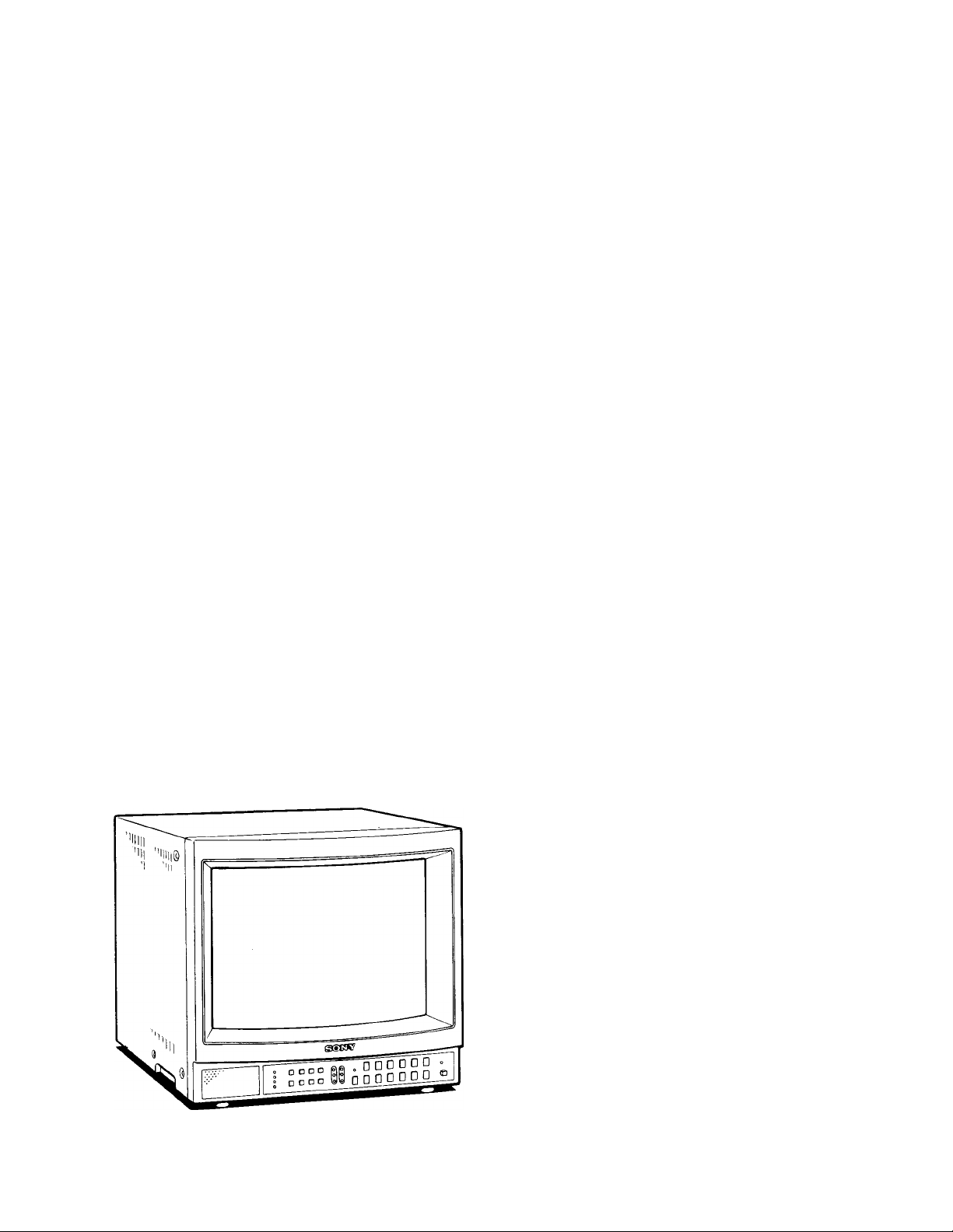
TRINITRON® Color Video Monitor
3-786-761-27 (1)
Operating Instructions Page 2
Before operating the unit, please read this manual thoroughly
and retain it for future reference.
Mode d’emploi Page 16
Avant la mise en service de cet appareil, prière de lire attentivement
ce mode d'emploi que l’on consen/era pour toute référence ultérieure.
© 1988 by Sony Corporation
This illustration shows
PVM-1342Q/PVM-1341.
Cette illustration représente les modèles
PVM-1342Q/PVM-1341.
Page 2
Ownei^s Record
The model and serial numbers are located on the rear.
Record the model and serial numbers in the spaces provided
belo\«. Refer to these numbers whenever you call upon your
Sony dealer regarding this product.
Model No..
. Serial No..
To prevent fire or shock hazard, do not expose the unit to rain or moisture.
are designed to provide reasonable protection against such
interference when operated in a commercial environment.
Operation of this equipment in a residential area is likely to
cause interference in which case the user at his own
expense will be required to take whatever measures may be
required to correct the interference.
Important-To insure that the complete system (including this
peripheral) is capable of complying with the FCC
requirements, it is recommended that the user make sure
that the individual equipment of the complete system has a
label with one of the following statements.
“this equipment has been tested with a Class A
Computing Device and has been found to comply with
Part 15 of FCC Rules.”
-or“This equipment complies with the requirements in Part
15 of FCC Rules for a Class A Computing Device.”
-or equivalent.
This symbol is intended to alert the user to
the presence of uninsulated “dangerous
voltage” within the product’s enclosure
that may be of sufficient magnitude to
constitute a risk of electric shock to
persons.
This symbol is intended to alert the user to
the presence of important operating and
maintenance (servicing) instructions in the
literature accompanying the appliance.
For the Customers in the USA
Warning — This equipment generates, uses, and can radiate
radio frequency energy and if not installed and used in
accordance with the instructions manual, may cause
interference to radio communications. It has been tested and
found to comply with the limits tor a Class A computing
device pursuant to Subpart J of Part 15 of FCC Rules, which
Page 3
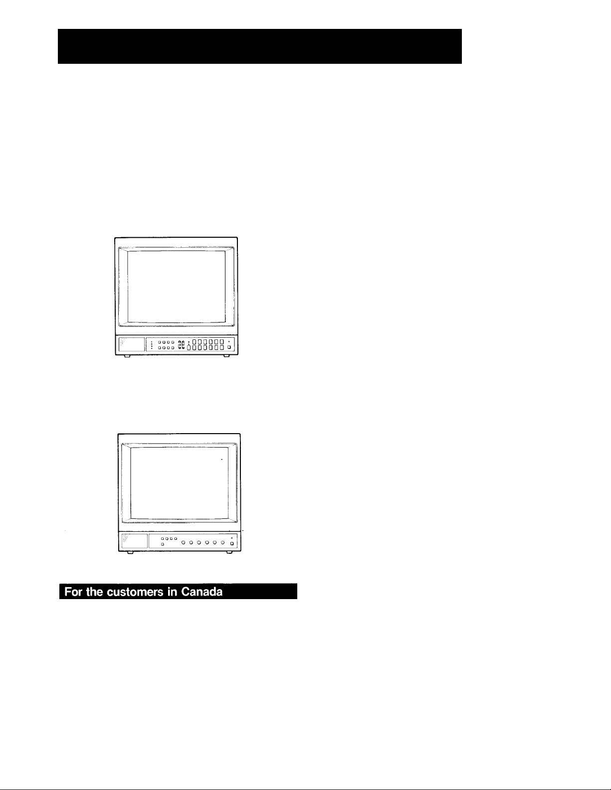
Table of Contents
I
Precautions
Precautions ....................................................................... 3
Features
Location and function of parts and controls....................... 6
Specifications....................................................................13
This instruction manual covers the following models. The
main differences are shown-on page 4.
PVM-1344Q/PVM-1342Q/PVM-1341
• PVM-1341 has no color system indicators.
• Only PVM-1344Q has a MEMORY button.
PVM-1340
...........................................................................
Front panel.................................................................... 6
Rear panel
....................................................................
4
10
On safety
• Operate the unit only on 120 V AC.
• Should any solid object or liquid fail into the cabinet,
unplug the unit and have it checked by qualified personnel
before operating it any further.
• Unplug the unit from the wall outlet if it is not to be used for
several days or more.
• To disconnect the AC power cord, pull it out by grasping
the plug. Never pull the cord itself.
On installation
• Allow adequate air circulation to prevent internal heat
build-up.
Do not place the unit on surfaces (rugs, blankets, etc.) or
near materials (curtains, draperies) that may block the
ventilation holes.
• Do not install the unit in a location near heat sources such
as radiators or air ducts, or in a place subject to direct
sunlight, excessive dust, mechanical vibration or shock.
On cleaning
To keep the unit looking brand-new, periodically clean it with
a soft cloth. Stubborn stains may be removed with a cloth
lightly dampened with a mild detergent solution. Never use
strong solvents such as thinner or benzine, or abrasive
cleansers since these will damage the cabinet. As a safety
precaution, unplug the unit before cleaning it.
This apparatus compiies with the Class A limits for radio
noise emissions set out in Radio Interference Regulations.
On repacking
Do not throw away the carton and packing materials. They
make an ideal container in which to transport the unit. When
shipping the unit to another location, repack it as illustrated
on the carton.
If you have any questions about this unit, contact your
authorized Sony dealer.
3
Page 4
Features
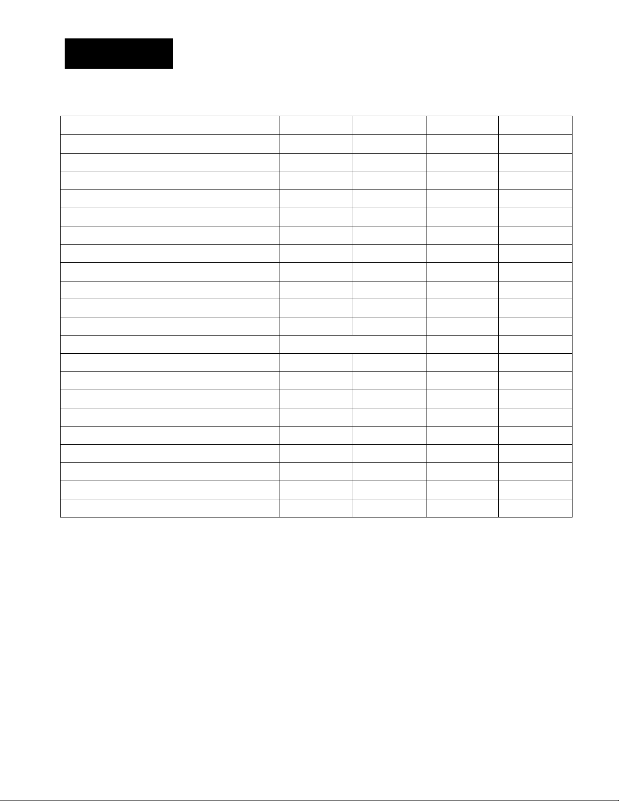
This chart shows the various features which your modei has (indicated as “Yes”).
1
Features PVM-1344Q PVM-1342Q
Automatic white balance circuit Yes Yes
SMPTE-C phosphor
Black-tinted Trinitron tube
Super Fine Pitch Trinitron picture tube
Analog RGB/component input/output
Analog RGB input/output
Digital RGB input (9-pin)
Y/C input (4-pin DIN) Yes Yes
VTR input (8-pin)
Control S input/output
Automatic termination of BNC-type input connectors Yes Yes
Color systems available
Comb filter
Blue only mode Yes Yes
Underscan mode
Horizontal/vertical delay mode
Yes
No No
Yes Yes
Yes No
No
No Yes
Yes
Yes Yes
PAL, SECAM, NTSC3.58 NTSC4.43
Yes Yes
Yes Yes
Yes
Yes
Yes
Yes
Yes
PVM-1341
Yes
No
Yes
No
No
Yes
Yes
Yes
Yes Yes
Yes
Yes
NTSC3.58 only
Yes
Yes Yes
Yes
Yes
PVM-1340
Yes
No
Yes
No
No
Input: Yes
Output; No
No
Yes
No
Yes
NTSC3.58 only
Yes
No
No
Users control memory
External sync input Yes Yes
Color temperature selector
Light-touch picture adjustment buttons
EIA standard 19-inch rack mounting Yes Yes
Yes
Yes
Yes
No
Yes
Yes
No
Yes
Yes
Yes
Yes
No
No
Yes
No
Yes
Page 5

Automatic white balance circuit
The automatic white balance circuit compensates for the
beam distortion, secular distortion of the cathode-ray tube,
etc., and always reproduces the same white display on the
screen. This allows an extended use of the monitor.
Super Fine Pitch Trinitron picutre tube
(PVM-1344Q/PVM-1342Q only)
The Super Fine Pitch Trinitron picture tube (0.25 mm aperture
grill) gives high resolution picture. Horizontal resolution is
more than 600 TV lines at the center of the picture. When
used as a character display, up to 2,000 characters (80
characters/line x 25 lines) can be displayed with great clarity.
Analog RGB/component connector (PVM-l344Qonly)
Analog RGB and component signals of a video equipment
can be input through this connector. The signals are
selected by the COMPO/RGB selector on the rear panel.
Analog RGB connector
Analog RGB signal of a video equipment can be input
through this connector.
Digital RGB input connector
Digital RGB signal from a microcomputer can be input
through this connector.
Y/C input connector
The video signal split into the chrominance signal (C) and the
luminance signal (Y) can be input through this connector,
eliminating the interference between the two signals which
tends to occur in a composite video signal and assuring the
video quality.
Comb Filter
When NTSC video signals are received, a comb filter
activates to increase the resolution, resulting in fine picture
detail without color spill or color noise.
Blue only mode
In the blue only mode, an apparent monochrome display is
obtained with all three cathodes driven with a blue signal.
This facilitates color saturation and phase adjustments and
observation of VCR noise.
Underscan mode (except PVM-1340)
The signal normally scanned outside of the screen can be
monitored in the underscan mode.
The bright scanning lines which may appear on the top edge
of the screen when the monitor is in the underscan mode are
caused by an internal test signal, rather than the input signal.
HorizontalArertical delay mode (except PVM-1340)
The horizontal and vertical sync signals can be checked
simultaneously in the HA/ delay mode.
Users control memory (PVM-l344Qonly)
The desired aperture, brightness, chroma and phase levels
can be memorized as the levels to be restored.
External sync input (except PVM-1340)
When the EXT SYNC (or ANALOG/DIGITAL (EXT SYNC))
button is depressed, the monitor can be operated on the
sync signal supplied from an external sync generator.
VTR input connector
When connected to a VCR having the 8-pin TV connector,
video and audio signals can be fed through this connector
with a single cable.
Control S connector (except PVM-1340)
When this connector is connected to the “control S” output
of other equipment, the remote controls of the aperture,
brightness, chroma, phase, contrast and volume settings are
possible.
Automatic temnination of BNC-type input connector
The BNC-type input connector is terminated at 75 ohms
inside, when no cable is connected to the output connector.
When the cable is connected to the output connector, the
75-ohms termination is automatically released, and the
signal input to the corresponding IN connector is output
from the output connector.
Four color systems available
(PVM-1344Q/PVM-1342Q only)
The monitor can display PAL, SECAM, NTSCs.se and
NTSC4.43* signals. The appropriate color system is selected
automatically.
* A signal of NTSC4.43 is obtained by playing back NTSC-
recorded video cassettes with a video tape recorder/player
especially designed for use with this system.
Color temperature selector
Color temperature of either 9,300°K or 6,500°K is selectable
with the COLOR TEMP selector. For precise adjustment, use
the BIAS and GAIN adjustment controls (except PVM-1340).
Light-touch picture adjustment buttons (except
PVM-1340)
The aperture, brightness, chroma, phase, contrast and
volume buttons can be adjusted by touching the buttons
lightly. The adjusted settings will be stored in memory even
when the monitor is turned off.
EiA standard 19-inch rack mounting
By using an optional MB-502A mounting bracket, the monitor
can be mounted in an EIA standard 19-inch rack. An optional
SLR-102 slide rail is also available. For details on mounting,
see the appropriate instruction manual.
Page 6
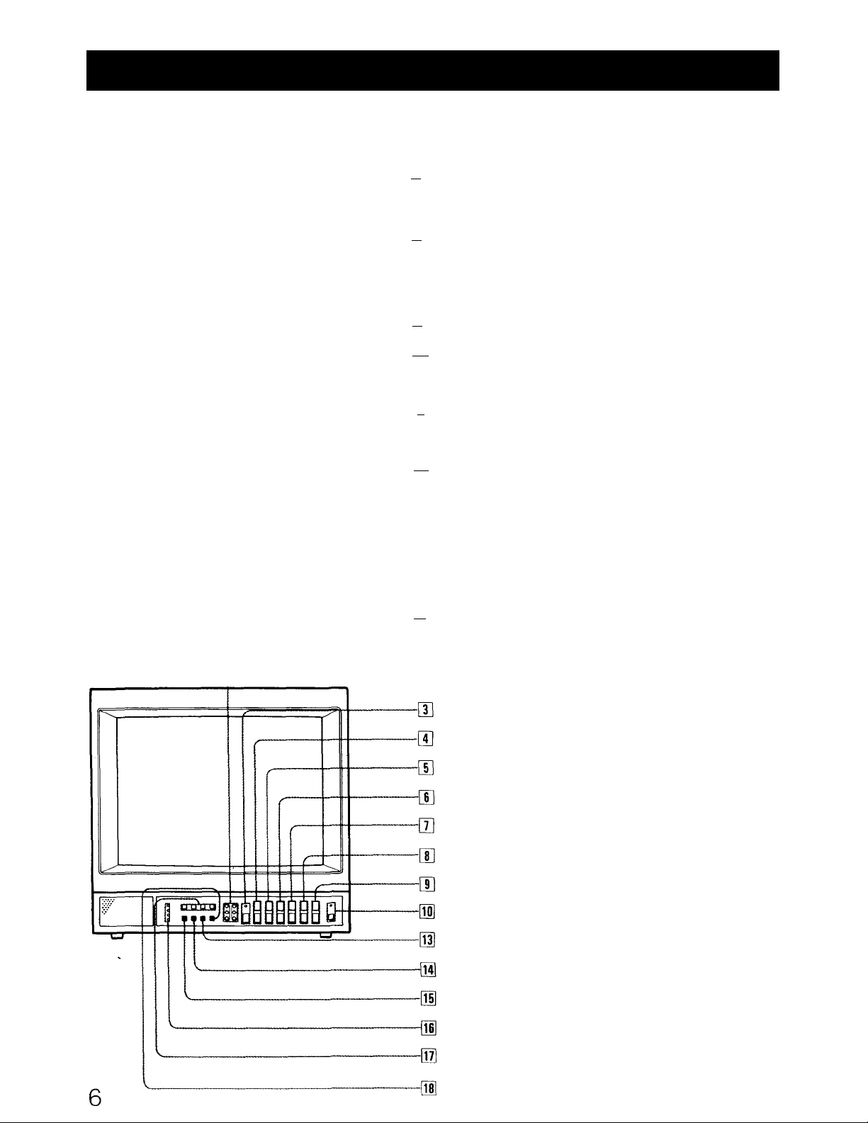
Location and Function of Parts and Controis
Front panel PVM-1344Q
-in BIAS and GAIN adjustment controls
-m MEMORY button
-in RESET button and response indicator
-[4] APERTURE buttons
"[|] BRIGHT (brightness) buttons
-in CHROMA buttons
-[71 PHASE buttons
-n CONTRAST buttons
~n VOL (volume) buttons
9 9 9 9
W
□DPPP n
3'
-[To] POWER switch and indicator
-Tn INPUT select buttons
Front panel PVM-1342Q/PVM-134t
-TH EXT SYNC button
-03] H-V DELAY button
-01 UNDER SCAN button
-01 BLUE ONLY button
-01 Color system indicators
-[01 BIAS and GAIN adjustment controls
H-V DELAY button
UNDER SCAN button
BLUE ONLY button
Color system indicators (except PVM-1341)
INPUT select buttons
ANALOG/DIGITAL (EXT SYNQTjutton
Page 7

|T] BIAS and GAIN adjustment controls
Used for white balance adjustment.
Gain and BIAS controls are provided for the R (red), G
(green) and B (blue) screens.
BIAS: Adjust the white balance and brightness of the
screen at the lowlight with these controls.
GAIN: Adjust the white balance and contrast of the
screen at the highlight with these controls.
[U MEMORY button
After setting the APERTURE, BRIGHT, CHROMA, and
PHASE controls to the desired levels, press this button
with a pencil or a similar object so that these levels can
be memorized and the response indicator lights up.
When the RESET button is pressed, the above control
settings, and not the factory set levels, will be restored. To
change the memorized levels, repeat the above
operations.
To release the memorized levels and restore the factory
set levels, while pressing this button, press the RESET
button.
[U RESET button and response indicator
Press to return the PHASE, CHROMA, BRIGHT and
APERTURE control settings to the factory set levels
(memorized levels for PVM-1444QM).
The response indicator flashes when the above buttons or
the RESET button is pressed.
[5 APERTURE buttons
Press + for more sharpness or - for less,
d] BRIGHT (brightness) buttons
Press + for more brightness or - for less.
[U CHROMA buttons
Press + for more color intensity or - for less.
|T] PHASE buttons
This button is effective only for the NTSC3.58 and NTSC4.43
color system.
Press GRN (green) to make the skin tones greenish or
PUR (purple) to make them purplish.
The APERTURE, CHROMA, PHASE control settings have no
effect on the pictures of analog RGB or digital RGB signals.
[|] CONTRAST buttons
Press + to make the contrast, color intensity and
brightness stronger or - to make them weaker.
|T]VOL (volume) buttons
Press + for more volume or - for less.
[H POWER switch and indicator
Depress to turn the monitor on.
The indicator will light up in green.
Press the switch again to turn the monitor off.
ini INPUT select buttons
Press to select the program to be monitored.
A: for a signal fed through the LINE A connectors.
B: for a signal fed through the LINE B connectors.
Y/C/VTR: for a signal fed through the Y/C-INPUT
connectors or VTR connector.
When both the Y/C-INPUT and VTR connectors are
connected to video equipment, the input signal fed
through the Y/C-INPUT connector has priority over the
one fed through the VTR connector.
ANALOG RGB/COMPONENT: for a signal fed through
the ANALOG RGB/COMPONENT connectors.
For connection, refer to the explanation of ANALOG
RGB/COMPONENT connectors on page 11.
[T2] EXT SYNC (external sync) button
Normally keep this button released (INT). The monitor
operates on the sync signal from the displayed composite
video signal.
To operate the monitor on an external sync signal fed
through the EXT SYNC connector on the rear panel,
depress the button (EXT).
[T|H-V DELAY button
Depress to observe the horizontal and vertical sync
signals at the same time.
The horizontal sync signal is displayed in the left quarter
of the screen; the vertical signal is displayed near the
center of the screen.
OH UNDER SCAN button
Depress for underscanning. The display size is reduced by
approximately 3% so that four corners of the raster are
visible.
[llBLUE ONLY button
Depress to turn off the red and green signals. A blue
signal is displayed as an apparent monochrome picture
on the screen. This facilitates “chroma” and “phase*”
control adjustments and observation of VCR noise.
* “Phase” control adjustment is effective only for the NTSC signals.
[I6] Color system indicators
The indicator of the color system being received lights up
in red.
53 INPUT select buttons
Press to select the program to be monitored.
A: for a signal fed through the LINE A connectors.
B: for a signal fed through the LINE B connectors.
Y/C/VTR: for a signal fed through the Y/C-INPUT
connectors or VTR connector.
When both the Y/C-INPUT and VTR connectors are
connected to video equipment, the input signal fed
through the Y/C-INPUT connector has priority over the
one fed through the VTR connector.
RGB: for a signal fed through the ANALOG RGB
connectors or DIGITAL RGB connector.
51ANALOG/DIGITAL (EXT SYNC) button
This button functions as ANALOG/DIGITAL selector and
EXT SYNC selector.
As ANALOG/DIGITAL selector
Depress to rfionitor a signal fed through the ANALOG
RGB connectors.
Release to monitor a signal fed through the DIGITAL RGB
connector.
For EXT SYNC selector
Depress to operate the monitor on an external sync signal
fed through the EXT SYNC connector on the rear panel
(EXT).
Release to operate the monitor on the sync signal from
the displayed composite video signal (INT).
7
Page 8
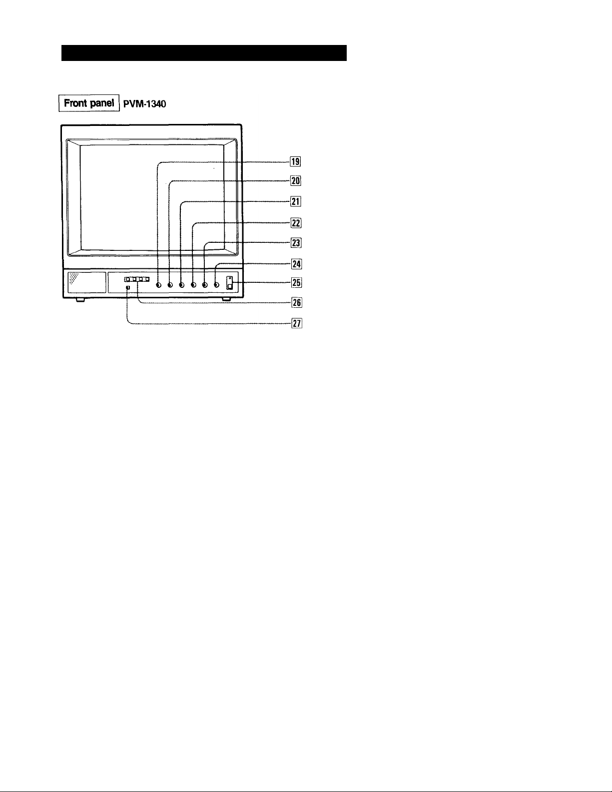
Location and Function of Parts and Controls
BRIGHT (brightness) control
CHROMA control
PHASE control
CONTRAST control
VOL (volume) control
POWER s\witch and indicator
INPUT select buttons
BLUE ONLY button
(H APERTURE control
Turn toward + for more sharpness or toward - for less.
m BRIGHT (brightness) control
Turn toward + for more brightness or toward - for less.
Normally set this control at the center detent position.
[21] CHROMA control
Turn toward + for more color intensity or toward - for
less.
[22] PHASE control
Turn toward GRN (green) to make the skin tones greenish
or toward PUR (purple) to make them purplish.
The APERTURE, CHROMA, PHASE control settings have no
effect on the pictures input through the ANALOG RGB IN
connector.
(23] CONTRAST control
Turn toward + to make the contrast, color intensity and
brightness stronger or toward - to make them weaker.
[24] VOL (volume) control
Turn toward + for more volume or toward - for less.
[2II POWER switch and indicator
Same as[l5.
[26] INPUT select buttons
Press to select the program to be monitored.
A; for a signal fed through the LINE A connectors.
B: for a signal fed through the LINE B connectors.
Y/C/VTR: for a signal fed through the Y/C-INPUT
connectors or VTR connector.
When both the Y/C-INPUT and VTR connectors are
connected to video equipment, the input signal fed
through the Y/C-INPUT connector has priority over the
one fed through the VTR connector.
ANALOG RGB: for a signal fed through the ANALOG
RGB input connectors.
[27] BLUE ONLY button
Same as [15].
8
Page 9
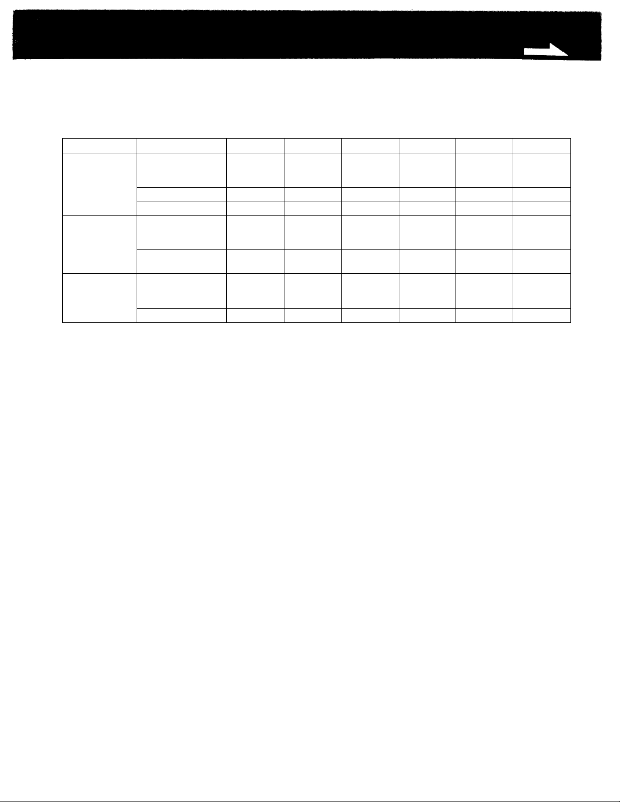
Picture Adjustment Buttons
The picture adjustment buttons of each monitor operate in the following input mode (indicated as “Yes”).
Model
PVM-1344Q
PVM-1342Q/
PVM-1341
PVM-1340
Input mode APERTURE BRIGHT CHROMA PHASE
•LINEA, LINEB
• Y/C
• VTR
Analog RGB
Component Yes Yes Yes No Yes
• LINEA, LINE B
•Y/C
•VTR
• Digital RGB
• Analog RGB
•LINEA, LINEB
•Y/C
•VTR
Analog RGB
Yes Yes Yes
No Yes No
Yes Yes
No Yes No No Yes
Yes Yes Yes
No
Yes No No Yes
Yes
Yes
(NTSC only)
No
Yes
(NTSC only)
Yes
(NTSC only)
CONTRAST
Yes
Yes
Yes
Yes
VOL
Yes
Yes
Yes
Yes
No
Yes
No
Page 10
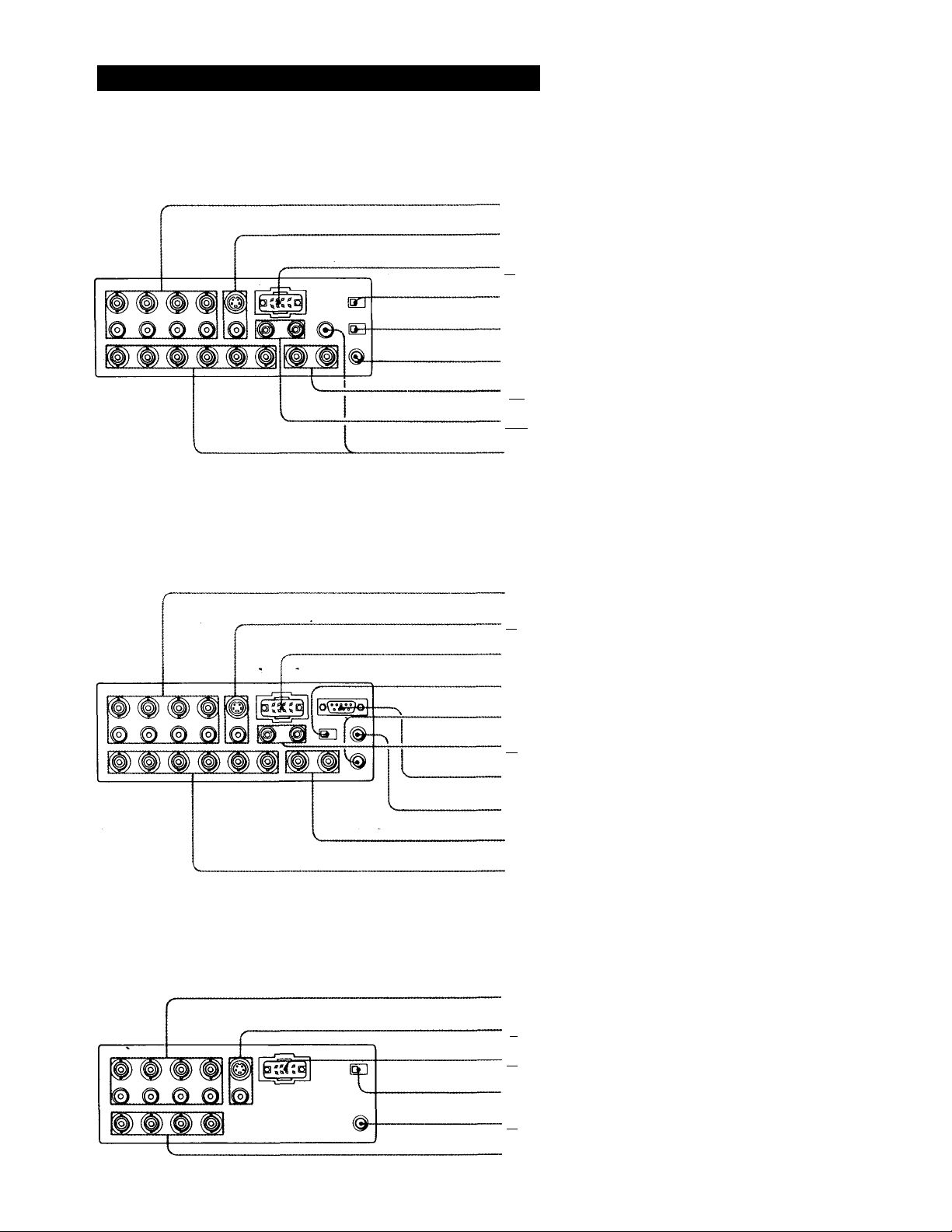
Location and Function of Parts and Controis
Rear panel PVM-1344Q
-U] LINE A, LINE B connectors
-H] Y/C-INPUT connectors
-in VTR input connectors
-(T] COLOR TEMP selector
-[5] COMPO/RGB selector
-g]- V HOLD control
~[T| EXT SYNC connectors
-|~8l CTRL S connectors
[I] ANALOG RGB/COM PON ENT connectors,
AUDIO IN connector
Rear panel PVM-1342Q/PVM-1341
Rear panel PVM-1340
-in LINE A, LINE B connectors
-in Y/C-INPUT connectors
-[T| VTR input connectors
-n COLOR TEMP selector
-g] V HOLD control
-g] CTRL S connectors
-|10] DIGITAL RGB connector
-[Ti! H CENT control
EXT SYNC connectors
ANALOG RGB connectors
10
-n LINE A, LINE B connectors
~n Y/C-INPUT connectors
-in VTR input connectors
-g] COLOR TEMP selector
-gl V HOLD control
-[15 ANALOG RGB IN connectors
Page 11

[T] LINE A, LINE B connectors
Two groups (A and B) of line input connectors for the
composite video and audio signals and their loop-through
output connectors.
To monitor the input signal fed through these connectors,
press the A or B input select button on the front panel.
VIDEO IN (BNC type): Connect to the video output of a
video equipment, such as a VCR or a color video
camera. For a loop-through connection, connect to the
video output of another monitor.
VIDEO OUT (BNC type): Loop-through output of the
VIDEO IN connector. Connect to the video input for a
VCR or another monitor.
When the cable is connected to this connector, the
75-ohms termination of the input is automatically
released, and the signal input to the VIDEO IN
connector is output from this connector.
AUDIO IN (phono jack): Connect to the audio output of a
VCR or to a microphone via a suitable microphone
amplifier. For a loop-through connection, connect to
the audio output of another monitor.
AUDIO OUT (phono jack): Loop-through output of the
AUDIO IN jack. Connect to the audio input of a VCR or
another monitor.
|T]Y/C-INPUT connectors (4-pin)
VIDEO: Connect to the Y/C separate output of a video
camera or a VCR.
AUDIO: Connect to the audio output of a video camera or
a VCR.
To monitor the input signal fed through these connectors,
press the Y/CA/TR button on the front panel.
jTjVTR input connectors (8-pin)
Line input for the video and audio signals. When
connected to the 8-pin TV connector of a VCR, the video
and audio playback signal from the VCR can be
connected with a single cable.
To monitor the input signal fed through this,connector,
press the Y/CATTR button on the front panel, with the
Y/C-INPUT connectors connected to no outputs.
When both VTR and Y/C-INPUT connectors are connected
to video equipment, the input signal fed through the
Y/C-INPUT connectors has priority over the one fed
through the VTR connectors.
[T]COLOR TEMP (temperature) selector
Select the color temperature position, 9300°K or 6500°K.
[TjCOMPO (component)/RGB selector
Set to COMPO to monitor component signal fed through
the R/R-Y, G/Y, B/B-Y connectors.
Set to RGB to monitor analog R/G/B signal fed through
the R/R-Y, G/Y, B/B-Y connectors.
[T] EXT SYNC (external sync) connectors (BNC type)
IN: Connect to the output of a sync generator.
To monitor the sync signal fed through this connector,
depress the EXT SYNC button.
OUT: Loop-through output of the SYNC IN connector.
Connect to the SYNC input of a video camera.
When the cable is connected to this monitor, the
75-ohms termination of the input is released, and the
signal input to the IN connector is output from this
connector.
[UCTRL S (control S) connectors (minijack)
For remote control of the APERTURE, BRIGHT,
CHROMA, PHASE, CONTRAST and VOL control buttons.
IN: Connect to the “control S” output of other equipment.
OUT: Connect to the CTRL S IN connector of another
monitor by using a connecting cord (miniplug-^
miniplug).
[9] ANALOG RGB/COMPONENT connectors (BNC type)
R/R-Y IN, GIY IN, B/B-Y IN:
To monitor the analog R/G/B signal, connect to the
analog R/G/B signal outputs of a video camera having no
sync signal.
Set the COMPO/RGB selector on the rear panel to RGB
and press the ANALOG RGB/COMPONENT button on
the front panel. When the EXT SYNC button is released,
the monitor operates on the sync signal from the G
channel.
To monitor the component signal, connect to the
R-Y/Y/B-Y component signal outputs of a Sony BetaCam
video camera. Set the COMPO/RGB selector on the rear
panel to COMPO and press the ANALOG RGB/
COMPONENT button on the front panel. When the EXT
SYNC button is released, the monitor operates on the
sync signal from the Y channel.
R/R-Y OUT, G/Y OUT, B/B-Y OUT:
Loop-through outputs of the R/R-Y IN, G/Y IN, B/B-Y IN
connectors.
For R/G/B signal, connect to the analog R/G/B signal
inputs of a video camera.
For component signal, connect to the R-Y/Y/B-Y
component signal inputs of a BETACAM video camera.
When the cables are connected to these connectors, the
75-ohms termination of the input is automatically
released, and the signal inputs to the R/R-Y IN, G/Y IN,
B/B-Y IN connectors are output from these connectors.
AUDIO IN: Connect to the audio output of video
equipment when the analog R/G/B or component
signal is input.
[6]V HOLD (vertical hold) control
Turn to stabilize the picture if it rolls vertically.
11
Page 12

Location and Function of Parts and Controls
i) DIGITAL RGB connector (9-pin)
Connect with a microcomputer having a digital (TTL level)
RGB video output.
To monitor the input signal fed through this connector,
press the RGB button and keep the ANALOG/DIGITAL
(EXT SYNC) button released.
For connection, be sure to use an optional SMF-520
connecting cable.
[Tj] H CENT (horizontal centering) control
When a digital R/G/B signal is monitored, turn to center
the picture if it is decentered.
[m EXT SYNC (external sync) connectors (BNC type)
IN: Connect to the output of a sync generator.
To monitor the sync signal fed through this connector,
depress the ANALOG/DiGITAL (EXT SYNC) button.
OUT: Loop-through output of the SYNC IN connector.
Connect to the SYNC input of a video camera.
When the cable is connected to this connector, the
75-ohms termination of the input is released, and the
signal input to the IN connector is output from this
connector.
[13] ANALOG RGB connectors (BNC type)
R/G/B IN: Connect to the analog R/G/B outputs of a
video camera.
To monitor a signal fed'through these connectors, press
the RGB button and depress the ANALOG/DIGITAL (EXT
SYNC) button.
R/G/B OUT: Loop-through outputs of the R/G/B IN
connectors. Connect to the analog R/G/B inputs of a
video camera.
When the cable is connected to these connectors, the
75-ohms termination of the input is released, and the
signal input to the R/G/B OUT connector is output from
these connectors.
OJ ANALOG RGB IN connectors (BNC type)
R/G/B IN: Connect to the analog R/G/B outputs of a
video camera.
SYNC IN: Connect to the SYNC output of a video
camera.
12
Page 13
Specifications
Video signal
Frequency response
Chrominance subcarrier attenuation
Band pass 3.58 MHz: 2 MHz equiband
Chrominance/luminance
Aperture correction
Synchronization AFC time constant: 1 msec
Line puli range Horizontal: ±500 Hz
Line input: More than 7 MFIz (-3 dB)
Y/C input: More than 8 MFIz (-3 dB)
Component (Y/R-Y/B-Y): More than 8 MFIz
(-3 dB)
R.G.B. (analog): More than 9 MFIz (-3 dB)
3.58 MHz: Less than -30 dB (comb filter)
4.43 MHz: Less than -36 dB (trap filter)
4.43 MHz: 2 MHz equiband
Time error
Composite: Less than ±100 nS
Y/C: Less than ±50 nS
Component: Less than ±50 nS
-4.5 to ±6.5dB(at 4.5 MHz)
Vertical: 8 Hz
Picture performance
Normal scan 7% overscan of CRT effective screen area
Linder scan 3% underscan of CRT effective screen area
H. lineality Less than 6%
V. lineality Less than 6%
Convergence Central area: 0.6 mm (Typical)
Peripheral area: 0.8 mm (Typical)
Raster size stability
High voltage regulation
Audio output 0.6 W (Max.)
CRT PVM-1344Q/PVM-1342Q:
Chromacity coordinates (SMPTE-C only)
Red 0.630
Green
Blue 0.155
Color temperature
AC regulation range
Power consumption
H: 1.0%, V: 1.5%
3%
SM PTE-C (American-standard-phosphor)
PVM-1341/PVM-1340: P-22
X
0.310
6,500 K/9,300 K (±8MPCD), selectable
110- 130 VAC. 50/60 Hz
Approx. 99 W
Y
0.340
0.595
0.070
Inputs
For all models
VIDEO IN: BNC connector
AUlO IN: phono jack
VTR: 8-pin connector (See “VTR connector” on page 14.)
Y/C-INPUT
VIDEO: 4-pin connector (See “Y/C-INPUT connector" on
page 15.)
AUDIO: phono jack
(tolerance ±0.01)
PVM-1344Q only
EXT SYNC: BNC connector
composite sync 1-4 Vp-p, negative, 75 ohms terminated
automatically with no cable connected to the output connector
ANALOG RGB/COMPONENT: BNC connector
R, G, B and Y channels: 0.7 Vp-p. ±6 dB, non composite
R-Y and B-Y channels: 0.7 Vp-fi, ±6 dB
(Standard color bar signal of 75-percent chrominance)
When the composite signal is fed to the G or Y channels, the
monitor can be activated in the internal sync mode.
75 ohms terminated automatically with no cable connected to
the output connector
CTRL S: Minijack
PVM-1342Q/PVM-1341 only
EXT SYNC: BNC connector
composite sync 1-4 Vp-p, negative, 75 ohms terminated
automatically with no cable connected to the output
connector
ANALOG RGB: BNC connector
0.7 Vp-p, ±6 dB, non composite
75 ohms terminated automatically with no cable connected to
the output connector
DIGITAL RGB: 9-pin connector (See “DIGITAL RGB connector” on
page 14.)
CTRL S: Minijack
PVM-1340
ANALOG RGB: 0.7 Vp-p,
75 ohms terminated
t6 dB, non composite
Outputs
For all models
VIDEO OUT: BNC connector. Loop-through
AUDIO OUT: Phono jack. Loop-through
PVM-1344Q only
EXT SYNC: BNC connector. Loop-through
ANALOG RGB/COMPONENT: BNC connector. Loop-through
CTRL S: Minijack, Loop-through
PVM-1342Q/PVM-1341 only
EXT SYNC: BNC connector. Loop-through
ANALOG RGB: BNC connector. Loop-through
CTRL S: Minijack, Loop-through
General
storage temperature range
Operating temperature range
Humidity 0-90%
Dimensions Approx. 346 x 340 x 412 mm (w/h/d)
Weight Approx. 16.5 kg (36 lb 6 oz)
-10°C to 40°C (14°F to 104°F)
0°Cto35°C(32°Fto 95°F)
(13%x i3i/;x I6V-, inches)
13
Page 14
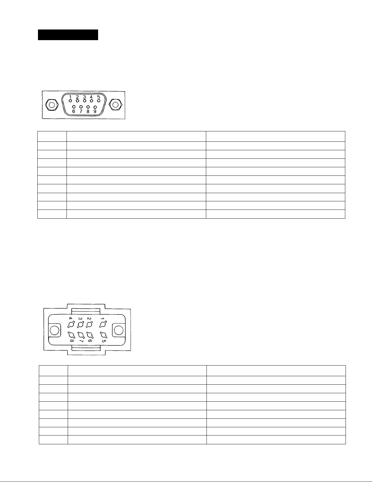
Specifications
Pin assignment
DiGiTAL RGB connector (9-pin)
Pin No. Signal
1
GND (ground)
Signal level
Ground
2 GND for the signal Ground
3 Red input
4 Green input
5 Blue input
Positive polarity (TTL level)
t
t
6 Intensity t
7
NC (no connection)
8 H-SYNC Positive or negative polarity (TTL level)
9
If the intensity function of Pin No. 6 is not used, set the
internal switch on the Qd board to the B position, and
connect the Pin No. 6 to the GND. With this setting, when the
positive intensity signal synchronized to the characters on
V-SYNC Same polarity as H-SYNC (TTL level)
It the specific intensity function, such as that of an IBM
microcomputer, is used, set the internal switch on the Qd
board to the A position, and feed the intensity control signal
to Pin No. 6.
the screen is fed, the luminance of the characters will be
increased.
VTR connector (8-pin)
Pin No.
1 Audio input
2 Video input
3 GND
4 NC
5 GND GND
6 GND
7 GND
8 GND
Signal
-5 dBs, high input impedance (more than 47 kilohms)
Composite 1 Vp-p, sync negative, 75 ohms
14
Description
GND
—
GND
GND
GND
Page 15
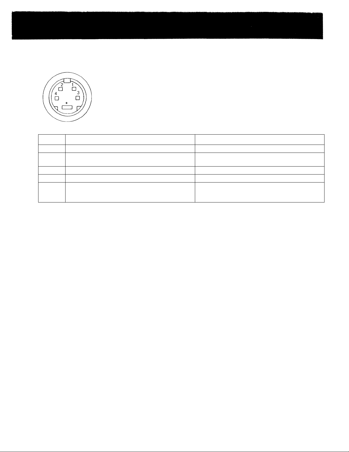
Y/C (Y/C separate) INPUT connector (4-pin)
Pin No.
1
2
3
4
*
Design and specifications subject to change without notice.
Y-input
CHROMA sub-carrier-input
GND for Y-input
GND forCHROMA-input
Slot for internal switch
Signal
Description
1 Vp-p, sync negative, 75 ohms
300 mVp-p, burst
Delay time between Y and C: within 0±100 nsec., 75 ohms
Ground
Ground
Press the switch inside this slot. The signal from
Y/C-INPUT connector has priority over the one from VTR
(8-pin) connector.
15
 Loading...