

Sony PRS-650 Service Manual
PRS-650
SERVICE MANUAL
Ver. 1.0 2010.08
Note:
Be sure to keep your PC used for service and
checking of this unit always updated with the
latest version of your anti-virus software.
In case a virus affected unit was found during
service, contact your Service Headquarters.
SPECIFICATIONS
Model name
PRS-650
Power source
Built-in rechargeable battery: 3.7 V DC, 940 mA
USB communication: Hi-Speed USB (USB 2.0 compliant)
Battery life (continuous playback)
Maximum Battery: Approx. 10,000 continuous page turns
when reading only *
*1 Measured using a text based content in ePub format and a
fully charged battery, consecutive page-turns at
approximately one second per page under the
recommended operating temperature. Actual battery life
may vary based on usage patterns and individual device.
User available capacity
Approx. 1.4 GB after initial setting
Depending on size of pre-loaded excerpts, available memory
capacity may vary.
Operating/charging temperature
41°F to 95°F (5°C to 35°C)
Dimensions (w/h/d)
Approx. 118.8 × 168 × 9.6 mm (4 2/3 × 8 3/5 × 19/50 inches)
Mass
Approx. 215 g (7.58 oz.)
Display:
152.4 mm (6") diagonal electrophoretic display
600 × 800 pixel, 0.151 × 0.153 pixel/mm
16-level gray scale
Expansion slots
Memory Stick PRO Duo™ slot, SD card slot
Design and specications are subject to change
without notice.
1
US Model
Canadian Model
AEP Model
UK Model
The contents of each book pre-loaded on this product are copyrighted works,
edited with the cooperation of the publisher.
Copyright laws prohibit copying the data of this product or the contents of this
manual (illustrations, related documents, etc.) in whole or in part without the
permission of the copyright holder. Additionally, use of the data of this product or
the contents of this manual is not allowed without Sony’s permission except for
personal use.
Besides individually enjoying, it is against the copyright law to use any audio or
picture you recorded without prior consent of the copyright holder. Accordingly,
Memory Stick™ media with content protected image or data can be only used
within the law.
Sony, the Sony logo, “BBeB”, “Reader”, “Reader Touch Edition” and their logos are
either trademarks or registered trademarks of Sony Corporation.
Duo”, “Memory Stick Duo”, “Memor y Stick Micro”, “M2”, “MagicGate” and their logos
are trademarks of Sony Corporation.
Bitstream is a registered trademark, and Dutch, Font Fusion, and Swiss are
trademarks, of Bitstream Inc.
Microsoft, Windows, Windows Vista and Windows Media are trademarks or
registered trademarks of Microsoft Corporation in the United States and / or other
countries.
Macintosh and Mac OS are trademarks of Apple Inc., registered in the U.S. and
other countries.
This PRS-650 contains Adobe® Reader® Mobile software under license from Adobe
Systems Incorporated, Copyright © 1995-2009 Adobe Systems Incorporated. All
rights reserved. Adobe and Reader are trademarks of Adobe Systems Incorporated.
MPEG Layer-3 audio coding technology and patents licensed from Fraunhofer IIS
and Thomson.
This product includes software developed by the OpenSSL Project for use in the
OpenSSL Toolkit. (http://www.openssl.org/) Copyright© 1998-2008 The OpenSSL
Project. All rights reserved. This product includes cryptographic software written
by Eric Young (eay@cryptsoft.com). This product includes software written by Tim
Hudson (tjh@cryptsoft.com). For details on OpenSSL License, refer to “END USER
LICENSE AGREEMENT” in the book list on the Reader.
All other system names and product names appearing in this document are the
registered trademarks or trademarks of their respective owners. Further, the
trademark ™ and registered trademark ® symbols are not indicated throughout this
document.
Program ©2010 Sony Corporation
Documentation ©2010 Sony Corporation
FLEXIBLE CIRCUIT BOARD REPAIRING
• Keep the temperature of soldering iron around 270 °C during
repairing.
• Do not touch the soldering iron on the same conductor of the
circuit board (within 3 times).
• Be careful not to apply force on the conductor when soldering
or unsoldering.
CAUTION
Danger of explosion if battery is incorrectly replaced.
Replace only with the same or equivalent type.
, “Memory Stick”, “Memory Stick PRO Duo”, “Memor y Stick PRO-HG
9-889-951-01
2010H05-1
2010.08
©
DIGITAL BOOK READER
Sony Corporation
Published by Sony Techno Create Corporation
PRS-650
SECTION 1
SERVICING NOTES
NOTE OF REPLACING BATTERY ASSY (BAT1)
Exchange it for an absolutely new part when you remove the BATTERY ASSY (BAT1) built into this set.
NOTE THE EACH BOARDS REPAIRING
The mount parts on each boards installed in this set cannot exchange with single. When the each boards are damaged, exchange
the entire mounted board.
NOTE OF REPLACING THE COMPLETE MAIN BOARD
OR PANEL ASSY
Please do the following work when you exchange complete MAIN
board or PANEL ASSY.
Note: INK INDICATOR 6inch ELEMENT is included in PANEL ASSY.
• Write VCOM: Refer to “20. Write VCOM” on page 11.
• REWRITING THE LUT: Refer to this page.
REWRITING THE LUT
As for INK INDICATOR 6inch ELEMENT, the parameter that rewrites the screen of each lot number is different. This parameter is
called LUT (Look Up Table).
When replacing the complete MAIN board or PANEL ASSY (including INK INDICATOR 6inch ELEMENT) you need to rewrite
the LUT.
However, rewriting is not required if the lot number is the same.
Note: LUT is written in IC2003 on the MAIN board.
Refer to the following for the “How to enter the test mode” and
“How to change the LUT”.
• How to enter the test mode
1. Connect the set to PC by the USB cable.
2. The fi le for the test mode is copied under the “READER”
drive.
Note: Confi rm the method of obtaining the fi le for test mode to each ser-
vice headquarters.
3. Remove the set from PC. Then, the power supply automatically becomes on.
4. Confi rm “Test Mode Avaliable” is displayed on the screen.
• How to change the LUT
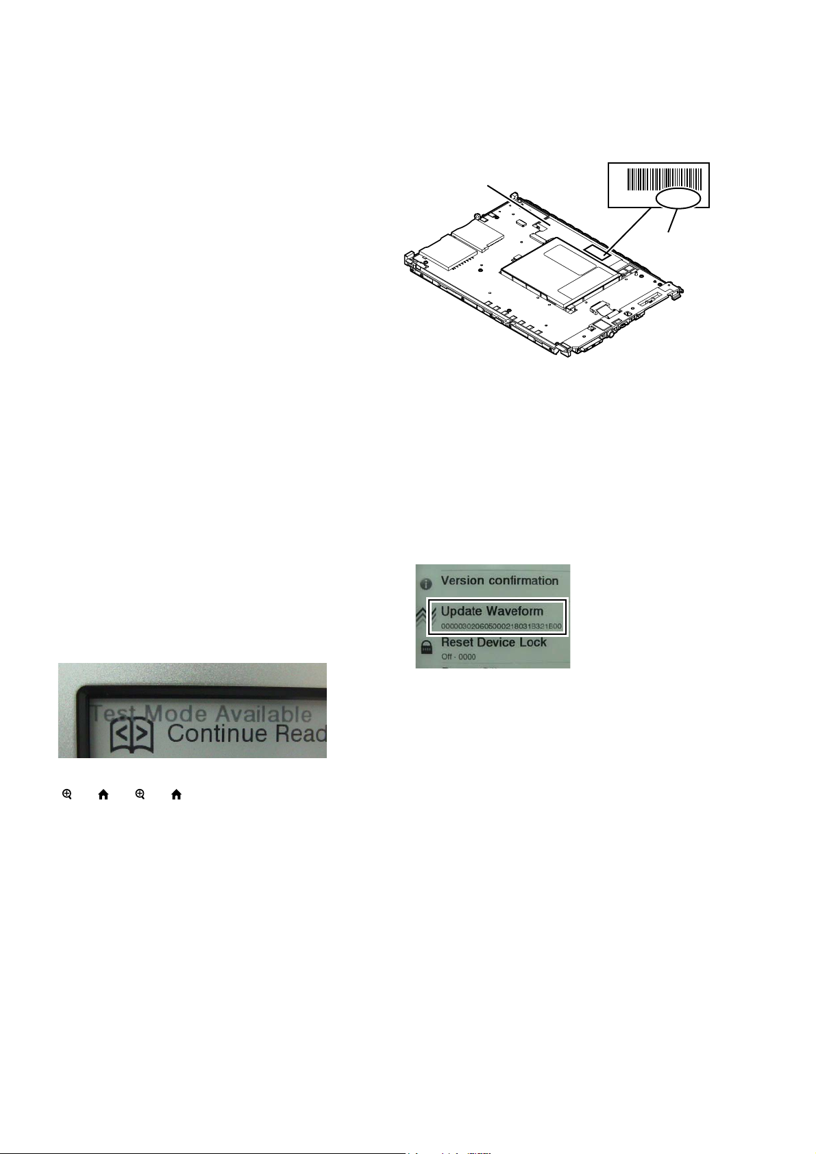
1. Confi rm the lot number of INK INDICATOR 6inch ELE-
MENT referring to the fi gure below.
Note: Remove the LED board when you do not see the lot number easily.
INK INDICATOR 6inch ELEMENT
-1.68 E505
lot number
2. Confi rm the version and the LUT fi le of LUT corresponding to
the lot number to each service headquarters.
3. Make the following folder under the “READER” drive.
/Sony Reader/software/data/
4. Copy the LUT fi le updated under the folder made in step 3, and
change the fi le name to “lut.bin”.
5. The current LUT version displayed at the lower side of “Update Waveform” on test mode menu 1
(Example: “000003020605000218031B321B00” in the fi gure
below).
(Example of displaying current LUT version)
5. Press the key as following order.
[] → [ ] → [ ] → [ ]
6. After a while, indicate the test mode menu, enter the test mode.
• Releasing the test mode
Slide the [POWER] key for 5 seconds or more to turn the power
off. Then, delete the fi le copied in “How to enter the test mode”
from the “READER” drive.
6. Touch the “Update Waveform” in the test mode menu page 1,
it starts rewriting LUT version.
7. After about 10 seconds, screen changes into all white.
8. Press [RESET] key and reboot the set.
9. Enter the test mode again, and confi rm LUT version has been
updated.
2
DISASSEMBLY
• This set can be disassembled in the order shown below.
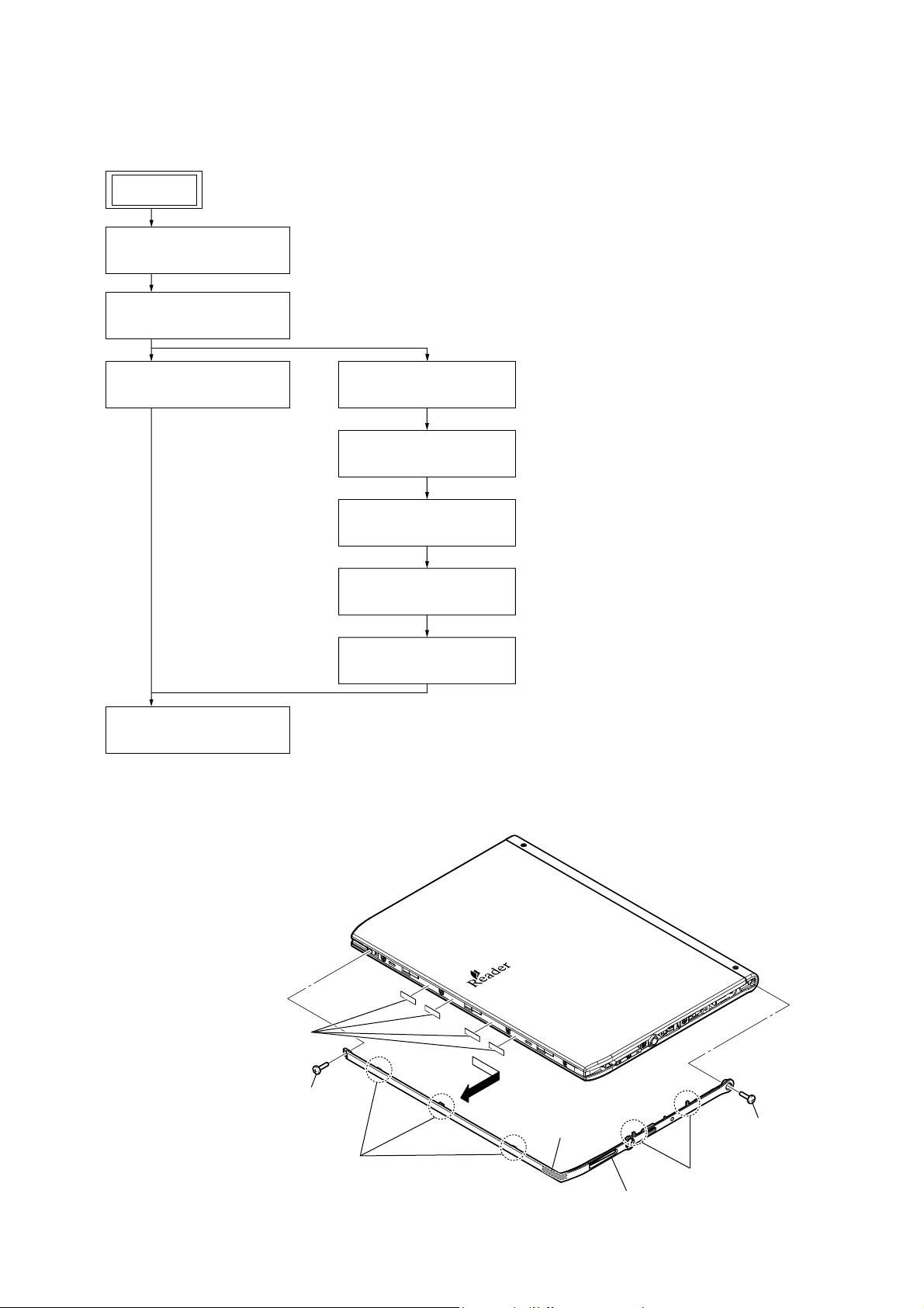
2-1. DISASSEMBLY FLOW
PRS-650
SECTION 2
SET
2-2. ORNAMENT ASSY
(Page 3)
2-3. CASE (REAR) BLOCK
(Page 4)
2-4. BATTERY ASSY (BAT1)
(Page 4)
Note 1: Please detach the STYLUS ASSY beforehand.
Note 2: Please take care not to lose the STYLUS ASSY.
2-5. FRAME (REAR) ASSY
(Page 5)
2-6. ORNAMENT (T) ASSY
(Page 5)
2-7. CASE ASSY
(Page 6)
2-8. LED board
(Page 6)
2-9. MAIN board
(Page 7)
2-10. PANEL ASSY
(Page 7)
Note: Follow the disassembly procedure in the numerical order given.
2-2. ORNAMENT ASSY
6 four adhesive sheets
(ornament)
2 shaft screw
5 three claws
4
adhesive sheet
(ornament)
– Rear side view –
1 screw
(M1.4)
3 two claws
7 ornament assy
3
PRS-650
s
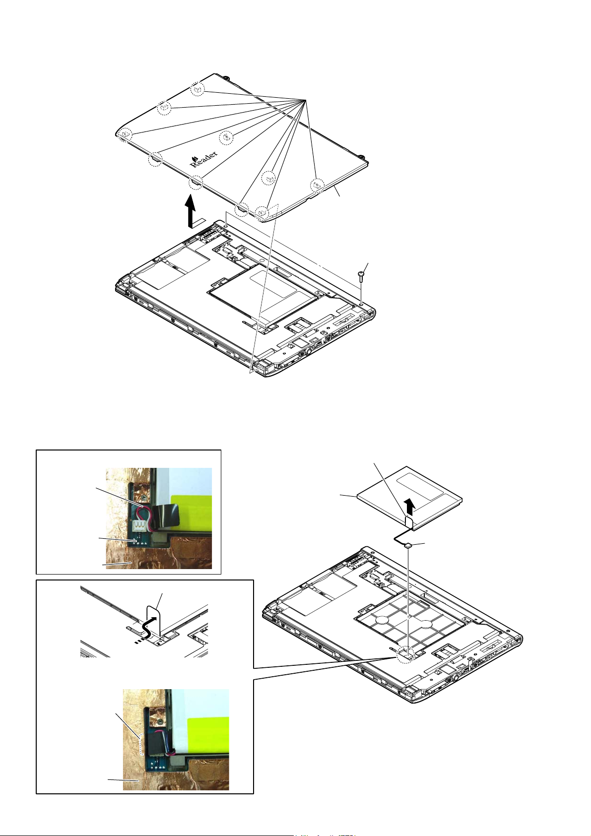
2-3. CASE (REAR) BLOCK
3 ten claws
4 case (rear) block
2
1 two shaft screw
– Rear side view –
2-4. BATTERY ASSY (BAT1)
Note 1: Exchange it for an absolutely new part when you remove the BATTERY ASSY (BAT1) built into this set.
:LUHSURFHVVLQJRIEDWWHU\DVV\%$7
wire of battery
assy (BAT1)
MAIN board
frame (rear) assy
1 Turn over the sheet (BATT).
4 battery assy (BAT1)
3 Pull this part of sheet (BATT) and lift the battery assy.
2 battery connector
(CN103)
Note 2: When installing
sheet (BATT) slip into the frame (rear) assy under.
sheet (BATT)
frame (rear) assy
the
battery assy (BAT1), make the
4
–5HDUVLGHYLHZ–
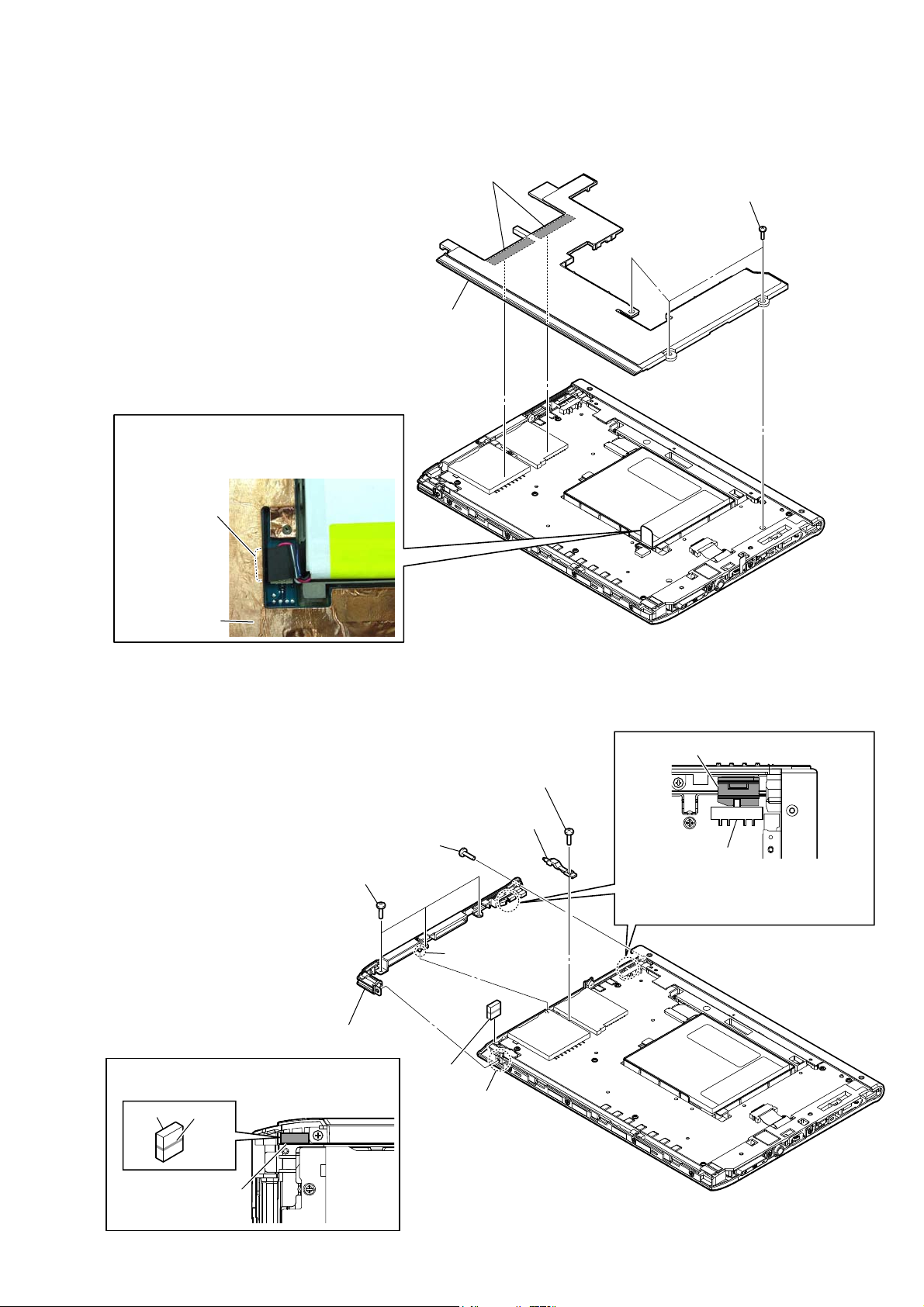
2-5. FRAME (REAR) ASSY
Peel copper leaf in two places.
2
Note 1:
paste it on CN2001 and CN2002 firmly.
When installing the
frame (rear) assy
3
frame (rear) assy
PRS-650
,
1 three precision pan screws
(M1.4)
Note 2: When installing
the sheet (BATT) slip into the frame (rear)
assy under after installing it.
sheet (BATT)
frame (rear) assy
the
frame (rear) assy, make
2-6. ORNAMENT (T) ASSY
4 precision pan screw
(M1.4)
5 three precision pan screws
(M1.4)
– Rear side view –
knob (power)
2 precision pan screw
(M1.4)
3 light guide (card)
switch
Note 2: When installing the ornament (T) assy,
the position of switch and knob (power)
is set and installed.
8 ornament (T) assy
Note 1: When installing the magnet, note the position
of marking of the magnet.
magnet
marking
marking side
7 boss
1 magnet
6 mold
– Rear side view –
5
 Loading...