

Sony PREMIERPRO GDM-F520 User Manual
â
Trinitron Color
Graphic Display
4-080-794-21 (1)
Operating Instructions
Mode d’emploi
Manual de instrucciones
US
FR
ES
CS
GDM-F520
GDM-F420
© 2000 Sony Corporation
Owner’s Record
The model and serial numbers are located at the rear of the unit.
Record these numbers in the spaces provided below. Refer to them
whenever you call upon your dealer regarding this product.
Model No.
Serial No.
WARNING
To prevent fire or shock hazard, do not expose the
unit to rain or moisture.
Dangerously high voltages are present inside the
unit. Do not open the cabinet. Refer servicing to
qualified personnel only.
FCC Notice
This equipment has been tested and found to comply with the limits
for a Class B digital device, pursuant to Part 15 of the FCC Rules.
These limits are designed to provide reasonable protection against
harmful interference in a residential installation. This equipment
generates, uses, and can radiate radio frequency energy and, if not
installed and used in accordance with the instructions, may cause
harmful interference to radio communications. However, there is no
guarantee that interference will not occur in a particular installation.
If this equipment does cause harmful interference to radio or
television reception, which can be determined by turning the
equipment off and on, the user is encouraged to try to correct the
interference by one or more of the following measures:
– Reorient or relocate the receiving antenna.
– Increase the separation between the equipment and receiver.
– Connect the equipment into an outlet on a circuit different from
that to which the receiver is connected.
– Consult the dealer or an experienced radio/TV technician for
help.
You are cautioned that any changes or modifications not expressly
approved in this manual could void your authority to operate this
equipment.
NOTICE
This notice is applicable for USA/Canada only.
If shipped to USA/Canada, install only a UL LISTED/CSA
LABELLED power supply cord meeting the following
specifications:
SPECIFICATIONS
Plug Type Nema-Plug 5-15p
Cord Type SVT or SJT, minimum 3
Length Maximum 15 feet
Rating Minimum 7 A, 125 V
× 18 AWG
NOTICE
Cette notice s’applique aux Etats-Unis et au Canada
uniquement.
Si cet appareil est export* aux Etats-Unis ou au Canada,
utiliser le cordon d’alimentation portant la mention UL LISTED/
CSA LABELLED et remplissant les conditions suivantes:
SPECIFICATIONS
Type de fiche Fiche Nema 5-15 broches
Cordon Type SVT ou SJT, minimum 3
Longueur Maximum 15 pieds
Tension Minimum 7 A, 125 V
ENERGY STAR Partner, Sony
As an
Corporataion has determined that this
product meets the
guidelines for energy efficiency.
× 18 AWG
ENERGY STAR
IMPORTANTE
Para prevenir cualquier mal funcionamiento y evitar daños, por
favor, lea detalladamente este manual de instrucciones antes
de conectar y operar este equipo.
INFORMATION
This product complies with Swedish National Council for Metrology
(MPR) standards issued in December 1990 (MPR II) for very low
frequency (VLF) and extremely low frequency (ELF).
INFORMATION
Ce produit est conforme aux normes du Swedish National Council
for Metrology de décembre 1990 (MPR II) en ce qui concerne les
fréquences très basses (VLF) et extremement basses (ELF).
INFORMACIÓN
Este producto cumple las normas del Consejo Nacional Sueco
para Metrología (MPR) emitidas en diciembre de 1990 (MPR II)
para frecuencias muy bajas (VLF) y frecuencias extremadamente
bajas (ELF).
This monitor complies with the TCO’99
guidelines.
If you have any questions about this product, you may call:
Sony Customer Information Center
1-800-222-SONY (7669)
or write to:
Sony Customer Information Center
1 Sony Drive, Mail Drop #T1-11, Park Ridge, NJ 07656
Declaration of Conformity
Trade Name: SONY
Model No.: GDM-F520/F420
Responsible Party: Sony Electronics Inc.
Address: 1 Sony Drive, Park Ridge, NJ 07656 USA
Telephone No.: 201-930-6972
This device complies with Part 15 of the FCC Rules. Operation
is subject to the following two conditions: (1) This device may
not cause harmful interference, and (2) this device must accept
any interference received, including interference that may
cause undesired operation.
2
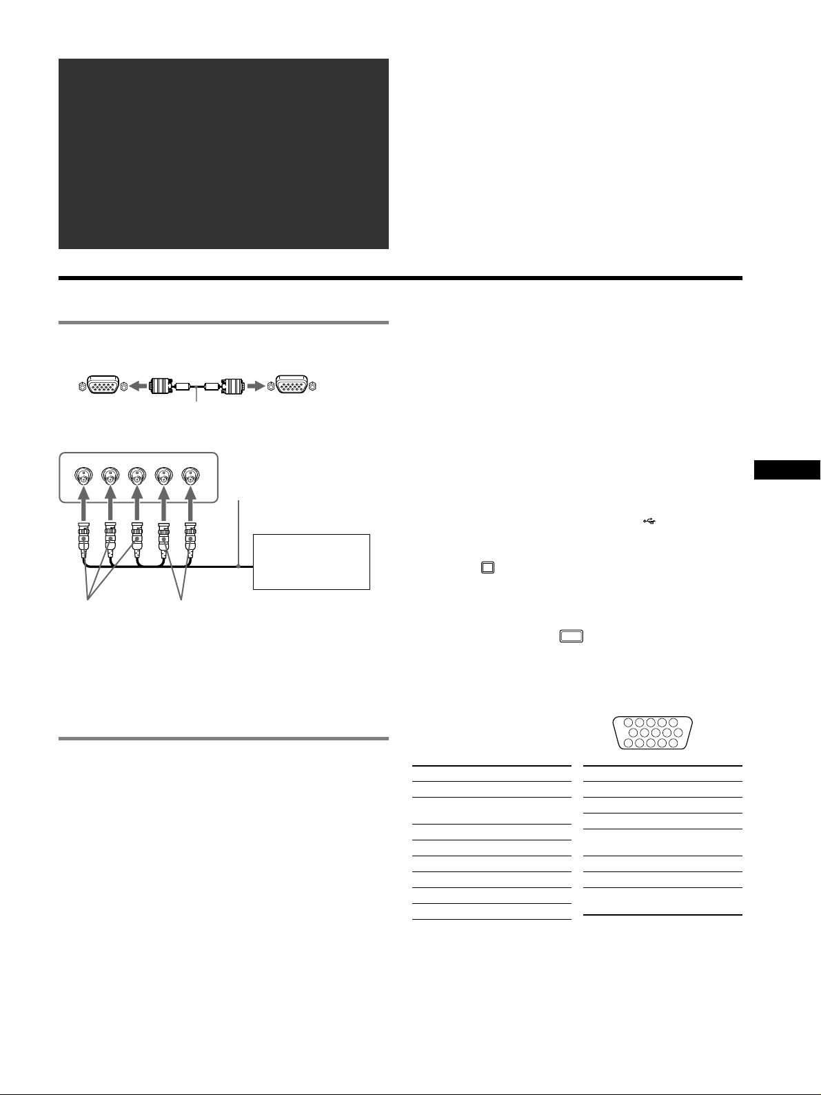
Table of Contents
Setup . . . . . . . . . . . . . . . . . . . . . . . . . . . . . . . . . . . 3
Adjustments . . . . . . . . . . . . . . . . . . . . . . . . . . . . . 4
Troubleshooting . . . . . . . . . . . . . . . . . . . . . . . . . . 6
Specifications . . . . . . . . . . . . . . . . . . . . . . . . . . . . 7
Precautions . . . . . . . . . . . . . . . . . . . . . . . . . . . . . . 8
Appendix . . . . . . . . . . . . . . . . . . . . . . . . . . . . . . . . . i
Preset mode timing table. . . . . . . . . . . . . . . . . . . . . i
TCO’99 Eco-document . . . . . . . . . . . . . Back Cover
Setup
•Trinitronâ is a registered trademark of Sony Corporation.
• Macintosh is a trademark licensed to Apple Computer, Inc., registered in
the U.S.A. and other countries.
• Windows
Corporation in the United States and other countries.
• IBM PC/AT and VGA are registered trademarks of IBM Corporation of
the U.S.A.
• VESA and DDC
Association.
•
ENERGY STAR is a U.S. registered mark.
• All other product names mentioned herein may be the trademarks or
registered trademarks of their respective companies.
• Furthermore, “
â
and MS-DOS are registered trademarks of Microsoft
ä
are trademarks of the Video Electronics Standard
ä” and “â” are not mentioned in each case in this manual.
1 Connecting your monitor to your computer
x To connect to the HD15 input connector
to HD15
video signal cable
(supplied)
to HD15 of the
connecting computer
x To connect to the 5 BNC connectors
RGBHDVD
video signal cable
(not supplied)
Refer to the preceding
examples to connect to
your computer.
to VIDEO IN R/G/B
to SYNC IN HD/VD
Connecting to a Macintosh or compatible
computer
When connecting this monitor to a Power Mac G3/G4 computer,
use the supplied adapter if necessary. Connect the supplied adapter
to the computer before connecting the cable. If you connect to
another version of Macintosh series computer, having 2 rows of
pins, you will need a different adapter (not supplied).
2 Turning on the monitor and computer
1 Connect the power cord to the monitor and press the
! (power) switch to turn on the monitor.
2 Turn on the computer.
No need for specific drivers
This monitor complies with the “DDC” Plug & Play standard and
automatically detects all the monitor’s information. No specific driver
needs to be installed to the computer.
The first time you turn on your PC after connecting the monitor, the setup
Wizard may appear on the screen. In this case, follow the on-screen
instructions. The Plug & Play monitor is automatically selected so that you
can use this monitor.
Notes
• Plug and Play is compatible with the HD15 connector only, and not
compatible with the 5 BNC connectors.
• Do not touch the pins of the video signal cable connector.
• Check the alignment of the HD15 connector to prevent bending the pins
of the video signal cable connector.
To select the input signal
You can connect two computers to this monitor using the HD15 and
BNC connectors. To select one of the two computers, use the
INPUT switch. The selected connector appears on the screen for 3
seconds.
Note
If no signal is input to the selected connector, NO SIGNAL appears on the
screen. After a few seconds, the monitor enters the power saving mode. If
this happens, switch to the other connector.
To connect Universal Serial Bus (USB) compliant
peripherals
Confirm that the monitor and computer are turned on, then
connect your computer to the USB connectors ( ) on the right side
of the monitor.
Connect your computer to the square upstream
connector
If a Windows message appears, follow the on-screen instructions
and select “Generic USB Hub”.
When connecting your USB compliant peripheral devices (e.g.,
printer, keyboard, mouse, scanner, etc.) connect the rectangular
downstream USB connector
Note
The monitor functions as a USB hub as long as the monitor is either “on” or
in power saving mode.
HD15 input connectors
Pin No. Signal
1Red
2 Green (Sync on
3Blue
4 ID (Ground)
5 DDC Ground*
6 Red Ground
7 Green Ground
8 Blue Ground
* DDC (Display Data Channel) is a standard of VESA.
() using the supplied USB cable.
().
5 4 3 2
1112131415
Pin No. Signal
9 DDC + 5V*
Green)
10 Ground
11 ID (Ground)
12 Bi-Directional
13 H. Sync
14 V. Sync
15 Data Clock
Data (SDA)*
(SCL)*
1
678910
US
3
Adjustments
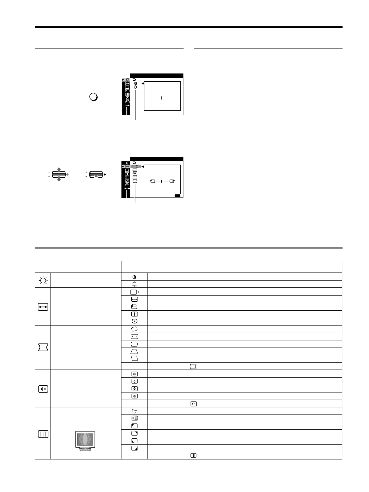
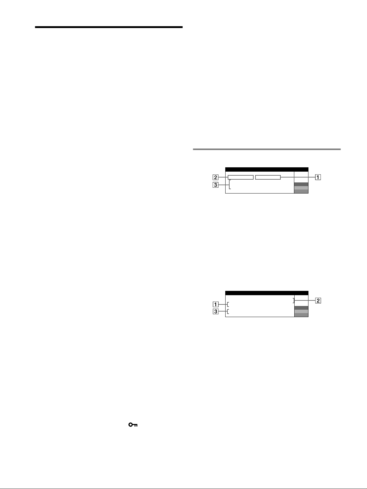
Navigating the menu
1 Press the MENU button to display the main menu.
CONTRAST
MENU
,
Main
menu
Sub
menu
2 Move the control button m/M to highlight the main
menu you want to adjust and press the control button.
SZE45/I CENTER
OK
OK
,,
Main
Sub
menu
menu
3 Select the sub menu you want to adjust and press the
control button.
4 Adjust with the control button.
/IBR GHT
CONTRAST
50
1024x768 / 85Hz
MENU
:
E
XIT
Adjusting the picture quality
(PICTURE EFFECT)
You can select the most appropriate picture mode from among 3
preset modes by pressing the PICTURE EFFECT button
repeatedly.
x PROFESSIONAL
For accurate and consistent display color. Choose this for
professional desktop publishing and graphic applications.
x STANDARD
For images with high contrast and brightness. Choose this mode for
commonly used applications, such as spreadsheets, word
processing, E-mail, or WEB surfing.
x DYN AM IC
For extremely vivid and photo-realistic images. Bright than
“STANDARD” mode, choose this for intense entertainment
software such as games, or DVD playback.
On-Screen menu adjustments
Main menu icons and adjustment
items
Adjusting the contrast and
brightness
Adjusting the size or centering of
the picture
1
*
1
*
Adjusting the shape of the picture
Adjusting the convergence
Adjusting the picture quality
Example of Moire
Sub menu icons and adjustment items
0 RESET: Returns all settings to their factory default settings.
2
*
T
B
0 RESET: Returns all settings to their factory default settings.
0 RESET: Returns all settings to their factory default settings.
Contrast
Brightness
Horizontal position
Horizontal size
Vertical position
Ver t ic a l s i ze
Auto Size Center
Rotating the picture
Expanding or contracting the picture sides
Shifting the picture sides to the left or right*
Adjusting the picture width at the top of the screen*
Shifting the picture to the left or right at the top of the screen*
1
*
1
1
1
Horizontally shifts red or blue shadows
Vertically shifts red or blue shadows
Vertically shifts red or blue shadows at the top of the screen
Vertically shifts red or blue shadows at the bottom of the screen
DEGAUSS: demagnetizes the monitor.
CANCEL MOIRE: adjusts the degree of moire cancellation until the moire is at a minimum.
LANDING: reduces any color irregularities in the screen’s top left corner to a minimum.*
LANDING: reduces any color irregularities in the screen’s top right corner to a minimum.*
*
2
2
LANDING: reduces any color irregularities in the screen’s bottom left corner to a minimum.*
LANDING: reduces any color irregularities in the screen’s bottom right corner to a minimum.*
1
2
2
4
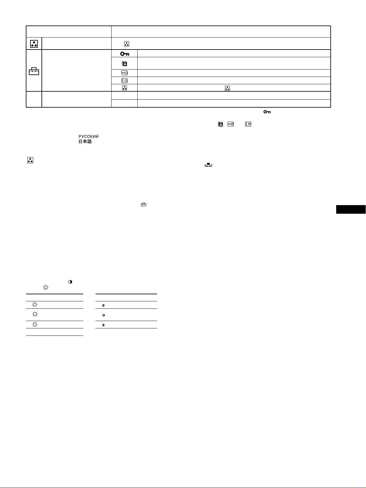
Main menu icons and adjustment
items
Adjusting the color of the picture See “ : To adjust the color of the picture”.
Additional settings
0 Resetting the adjustments
1
*
This adjustment is effective for the current input signal.
2
*
This adjustment is effective for all input signals.
3
*
Language Menu
• ENGLISH • NEDERLANDS: Dutch
• FRANÇAIS: French • SVENSKA: Swedish
• DEUTSCH: German • : Russian
• ESPAÑOL: Spanish • : Japanese
• ITALIANO: Italian
Sub menu icons and adjustment items
Protecting adjustment data (CONTROL LOCK)
Selecting the on-screen menu language/Confirming the monitor’s information LANGUAGE/
INFORMATION
Changing the menu’s position for horizontal adjustment
Changing the menu’s position for vertical adjustment
Selecting the color adjustment mode (See “ : To adjust the color of the picture”.)
1
Resetting all the adjustment data for the current input signal.*5 Select “OK”.
*
01
2
Resetting all of the adjustment data for all input signals. Select “OK”.
*
02
4
*
3
*
*4Only the ! (power) switch, EXIT, and (CONTROL LOCK) menu
will operate.
5
The menu items , and are not reset by this method.
*
: To adjust the color of the picture
The COLOR settings allow you to adjust the picture’s color
temperature by changing the color level of the white color field.
Colors appear reddish if the temperature is low, and bluish if the
temperature is high. This adjustment is useful for matching the
monitor’s color to a printed picture’s colors.
Select one of the color temperature setting modes from among
4 modes; EASY, PRESET, EXPERT, and sRGB on (OPTION)
menu.
x EASY (Default setting)
You can adjust the color temperature from 5000K to 11000K.
x PRESET
You can select the preset color temperature from 5000K, 6500K, or
9300K. The default setting is 9300K.
x EXPERT
You can make additional fine adjustments to the color by selecting
this mode. GAIN ( ) adjusts the bright areas of the screen, while
BIAS ( ) adjusts the dark areas of the screen.
Select for Select for
R R (Red) BIAS R R (Red) GAIN
G
B B (Blue) BIAS B B (Blue) GAIN
0 RESET
G (Green)
BIAS
G G (Green) GAIN
To restore the color from the EASY, PRESET, or sRGB
modes ( IMAGE RESTORATION)
You can restore the color to the original factory quality levels. Before using
this feature, the monitor must have been in normal operation mode (green
power indicator on) for at least 30 minutes. You may need to adjust your
computer’s power saving settings. If the monitor has not been on for at least
30 minutes, the “AVAILABLE AFTER WARM UP” message will appear.
Also, this function may gradually lose its effectiveness due to the natural
aging of the Trinitron picture tube.
US
x sRGB
The sRGB color setting is an industry standard color space protocol
designed to correlate the colors displayed on the monitor and those
printed. In order to display the sRGB colors correctly (γ = 2.2,
6500K), select the sRGB mode and set the PROFESSIONAL mode
of PICTURE EFFECT (page 4) and your connected computer to the
sRGB profile. If you select sRGB, you cannot operate the
CONTRAST/BRIGHT menu adjustments.
5
Troubleshooting
x No picture
If the ! (power) indicator is not lit
• Check that the power cord is properly connected.
• Check that the ! (power) switch is in the “on” position.
The ! (power) indicator is orange
• Check that the video signal cable is properly connected and all plugs
are firmly seated in their sockets.
• Check that the INPUT switch setting is correct.
• Check that the HD15 video input connector’s pins are not bent or
pushed in.
• Check that the computer’s power is “on”.
• The computer is in power saving mode. Try pressing any key on the
computer keyboard or moving the mouse.
• Check that the graphic board is completely seated in the proper bus
slot.
If the ! (power) indicator is green or flashing orange
• Use the Self-diagnosis function.
x Picture flickers, bounces, oscillates, or is scrambled
• Isolate and eliminate any potential sources of electric or magnetic
fields such as other monitors, laser printers, electric fans, fluorescent
lighting, or televisions.
• Move the monitor away from power lines or place a magnetic shield
near the monitor.
• Try plugging the monitor into a different AC outlet, preferably on a
different circuit.
• Try turning the monitor 90° to the left or right.
• Check your graphics board manual for the proper monitor setting.
• Confirm that the graphics mode and the frequency of the input signal
are supported by this monitor (see “Preset mode timing table” on
page i). Even if the frequency is within the proper range, some
graphics board may have a sync pulse that is too narrow for the
monitor to sync correctly.
• Adjust the computer’s refresh rate (vertical frequency) to obtain the
best possible picture.
x Picture is fuzzy
• Adjust the contrast, brightness, and PICTURE EFFECT.
• Degauss the monitor.*
• Adjust the degree of moire cancellation until the moire is minimal,
or set CANCEL MOIRE to OFF.
x Picture is ghosting
• Eliminate the use of video cable extensions and/or video switch
boxes.
• Check that all plugs are firmly seated in their sockets.
x Picture is not centered or sized properly
• Perform the Auto Size Center function.
• Adjust the size or centering. Note that with some input signals and/
or graphics board the periphery of the screen is not fully utilized.
• Just after turning on the power switch, the size/center may take a
while to adjust properly.
x Edges of the image are curved
• Adjust the geometry.
x Wavy or elliptical pattern (moire) is visible
• Adjust the degree of moire cancellation until the moire is minimal.
• Change your desktop pattern.
x Color is not uniform
• Degauss the monitor.* If you place equipment that generates a
magnetic field, such as a speaker, near the monitor, or if you change
the direction the monitor faces, color may lose uniformity.
• Adjust the landing.
x White does not look white
• Adjust the color temperature.
• Check that the 5 BNC connectors are connected in the correct order.
x Monitor buttons do not operate ( appears on the
screen)
• If the control lock is set to ON, set it to OFF.
x Letters and lines show red or blue shadows at the
edges
• Adjust the convergence.
x USB peripherals do not function
• Check that the appropriate USB connectors are securely connected.
• Turn the monitor OFF and then ON again, then reconnect USB cable.
• If you connect a keyboard or mouse to the USB connectors and then
boot your computer for the first time, the peripheral devices may not
function. First connect the keyboard and mouse directly to the
computer and set up the USB compliant devices. Then connect them
to this monitor.
• Install the latest version of the device driver on your computer.
Contact your device’s manufacturer for information about the
appropriate device driver.
x A hum is heard right after the power is turned on
• This is the sound of the auto-degauss cycle. When the power is
turned on, the monitor is automatically degaussed for a few seconds.
* If a second degauss cycle is needed, allow a minimum interval of
20 minutes for the best result. A humming noise may be heard, but this is
not a malfunction.
On-screen messages
IIONNFORMAT
MON I I I NGS WORKTOR
NPUT
I
ACT
CHECK
CHECK
2:NOBYS
I VATE
S GNAL C AB LEI
I NPUT SELECTOR
1 If “NO SIGNAL” appears:
This indicates that no signal is input from the selected connector.
2 Shows the currently selected connector.
3 Shows the remedies.
• If ACTIVATE BY COMPUTER appears on the screen, try
pressing any key on the computer or moving the mouse, and
confirm that your computer’s graphic board is completely seated
in the correct bus slot.
• If CHECK SIGNAL CABLE appears on the screen, check that
the monitor is correctly connected to the computer.
• If CHECK INPUT SELECTOR appears on the screen, try
changing the input signal.
IIONNFORMAT
MON I I I NGS WORKTOR
NPUT
I1:.200 0 /kHz 85Hz
OUT OF SCAN
CHANGE
S GNAL TIIINGM
1 If “OUT OF SCAN RANGE” appears:
This indicates that the input signal is not supported by the monitor’s
specifications.
2 Shows the input signal frequency.
3 Shows the remedies.
CHANGE SIGNAL TIMING appears on the screen. If you are
replacing an old monitor with this monitor, reconnect the old
monitor. Then adjust the computer’s graphic board so that the
horizontal frequency is between 30 – 137 kHz (GDM-F520),
30 – 115 kHz (GDM-F420), and the vertical frequency is between
48 – 170 Hz.
GNALI
COMPUTER
RANGE
W
R
G
B
W
R
G
B
6
To display this monitor’s name, serial number, and
date of manufacture.
While the monitor is receiving a
video signal, press and hold the
MENU button for more than
5 seconds to display this
monitor’s information box.
INFORMATION
MODEL : GDM F520
SER NO : 1234567
MANUFACTURED
: 2000-52
W
R
G
B
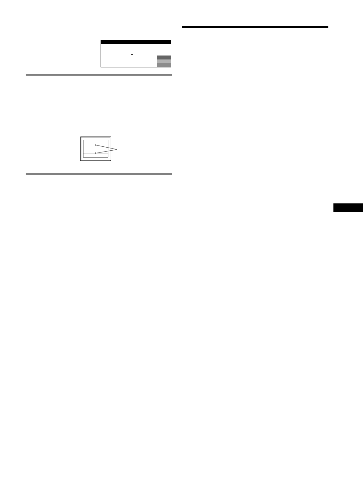
If thin lines appear on the screen
(damper wires)
These lines do not indicate a malfunction; they are a normal
effect of the Trinitron picture tube with this monitor. These are
shadows from the damper wires used to stabilize the aperture grille.
The aperture grille is the essential element that makes a Trinitron
picture tube unique by allowing more light to reach the screen,
resulting in a brighter, more detailed picture.
Damper
wires
Self-diagnosis function
This monitor is equipped with a self-diagnosis function. If there is
a problem with your monitor or computer(s), the screen will go
blank and the ! (power) indicator will either light up green or flash
orange. If the ! (power) indicator is lit in orange, the computer is
in power saving mode. Try pressing any key on the keyboard or
moving the mouse.
x If the ! (power) indicator is green
1 Disconnect any plugs from the video input 1 and 2
connectors, or turn off the connected computer(s).
2 Turn the monitor OFF and then ON.
3 Hold the control button upward for a few seconds
before the monitor enters power saving mode.
If all 4 color bars appear (white, red, green, blue), the monitor is
working properly. Reconnect the video input cables and check the
condition of your computer(s).
If the color bars do not appear, there is a potential monitor failure.
Inform your authorized Sony dealer of the monitor’s condition.
x If the ! (power) indicator is flashing orange
Turn the monitor OFF and then ON.
Specifications
CRT
0.22 mm aperture grille pitch, 90-degree deflection, FD Trinitron
GDM-F520 21 inches measured diagonally
GDM-F420 19 inches measured diagonally
Viewable image size
GDM-F520 Approx. 403.8
GDM-F420 Approx. 365
Resolution (H:Horizontal, V:Vertical)
GDM-F520 Maximum: H: 2048 dots, V: 1536 lines
GDM-F420 Maximum: H: 1920 dots, V: 1440 lines
Input signal levels
Video signal: Analog RGB: 0.700 Vp-p (positive), 75
SYNC signal: H/V separate or composite sync:
Standard image area
GDM-F520 Approx. 388
GDM-F420 Approx. 352
Deflection frequency (H:Horizontal, V:Vertical)
GDM-F520 H: 30 to 137 kHz, V: 48 to 170 Hz
GDM-F420 H: 30 to 115 kHz, V: 48 to 170 Hz
AC input voltage/current
Power Consumption (with no USB devices connected)
GDM-F520 Approx. 145 W
GDM-F420 Approx. 135 W
Operating temperature
Dimensions
GDM-F520 Approx. 497
GDM-F420 Approx. 446
Mass
GDM-F520 Approx. 30 kg (66 lb 2 oz)
GDM-F420 Approx. 26 kg (57 lb 5 oz)
Plug and Play DDC2B/DDC2Bi
Supplied accessories
19.8" viewing image
18.0" viewing image
Recommended: H: 1600 dots, V: 1200 lines
Recommended: H: 1280 dots, V: 1024 lines
TTL 2 k
Sync on Green: 0.3 Vp-p (negative)
3
(15
/8 × 11 1/2 inches) or
Approx. 364
3
/8 × 11 1/2 inches)
(14
7
(13
/8 × 10 1/2 inches) or
Approx. 330
(13
× 10
100 to 240 V, 50 – 60 Hz, 2.0 – 1.0 A
10 ºC to 40 ºC
5
(19
/8 × 19 3/4 × 19 1/4 inches)
5
(17
/8 × 18 5/8 × 18 1/4 inches)
Power cord
HD15 video signal cable
USB cable
Exclusive Power Mac G3/G4 adapter
This instruction manual
× 302.2 mm (w/h) (16 × 12 inches)
× 274 mm (w/h) (14
Ω, Polarity free
× 291 mm (4:3)
× 291 mm (5:4)
× 264 mm (4:3)
× 264 mm (5:4)
1
/2 inches)
× 499 × 487 mm (w/h/d)
× 472 × 463 mm (w/h/d)
3
/8 × 10 7/8 inches)
Ω
US
If the ! (power) indicator lights up green, the monitor is working
properly.
If the ! (power) indicator is still flashing, there is a potential
monitor failure. Count the number of seconds between orange
flashes of the ! (power) indicator and inform your authorized Sony
dealer of the monitor’s condition. Be sure to note the model name
and serial number of your monitor. Also note the make and model
of your computer and graphics board.
(continued)
7
 Loading...