

Page 1

PFM-510A1WU/510A1WE/510A1WJ
3-867-473-01 (1)
Flat Panel Monitor
Operating Instructions
Mode d’emploi
Bedienungsanleitung
Manual de instrucciones
Istruzioni per l’uso
取扱説明書
お買い上げいただきありがとうございます。
この取扱説明書には、事故を防ぐための重要な注意事項と製品の取り扱
いかたを示しています。この取扱説明書をよくお読みのうえ、製品を安
全にお使いください。お読みになったあとは、いつでも見られるところ
に必ず保管してください。
電気製品は安全のための注意事項を守らないと、
火災や人身事故になることがあります。
GB
FR
DE
ES
IT
JP
PFM-510A1WU
PFM-510A1WE
PFM-510A1WJ
1999 by Sony Corporation
Page 2

WARNING
Owner’s Record
The model and serial numbers are located on the rear.
Record the model and serial numbers in the spaces provided
below. Refer to these numbers whenever you call upon your
Sony dealer regarding this product.
Model No.
To prevent fire or shock hazard, do not
expose the unit to rain or moisture.
For the customers in the U.S.A.
This equipment has been tested and found to comply with
the limits for a Class A digital device, pursuant to Part 15 of
the FCC Rules. These limits are designed to provide
reasonable protection against harmful interference when the
equipment is operated in a commercial environment. This
equipment generates, uses, and can radiate radio frequency
energy and, if not installed and used in accordance with the
instruction manual, may cause harmful interference to radio
communications. Operation of this equipment in a residential
area is likely to cause harmful interference in which case the
user will be required to correct the interference at his own
expense.
You are cautioned that any changes or modifications not
expressly approved in this manual could void your authority
to operate this equipment.
For the customers in Canada
This class A digital apparatus complies with Canadian ICES-
003.
Serial No.
For PFM-510A1WE users
THIS APPARATUS MUST BE EARTHED
IMPORTANT
The wires in this mains lead are coloured in accordance with
the following code:
Green-and-yellow : Earth
Blue : Neutral
Brown : Live
As the colours of the wires in the mains lead of this
apparatus may not correspond with the coloured markings
identifying the terminals in your plug proceed as follows:
The wire which is coloured green-and-yellow must be
connected to the terminal in the plug which is marked with
the letter E or by the safety earth symbol I or coloured
green or green-and-yellow.
The wire which is coloured blue must be connected to the
terminal which is marked with the letter N or coloured black.
The wire which is coloured brown must be connected to the
terminal which is marked with the letter L or coloured red.
Voor de klanten in Nederland
Bij dit produkt zijn batterijen geleverd.
Wanneer deze leeg zijn, moet u ze niet
weggooien maar inleveren als KCA.
The socket-outlet should be installed near the equipment
and be easily accessible.
Note
When you connect a computer to this monitor,
attach the supplied ferrite cores. If you do not do
this, this monitor will not conform to mandatory
FCC/IC/CE (EN55022) standards.
For the customers in Europe
This is a Class A product. In a domestic environment, this
product may cause radio interference in which case the user
may be required to take adequate measures.
2 (GB)
Attaching the ferrite cores
Set the ferrite cores on the both ends of the AC
power cord. Close the lid tightly until the clamps
click.
or
Clamps
Page 3

Table of Contents
Precautions ............................................................... 4 (GB)
Features..................................................................... 5 (GB)
Location and Function of Parts and Controls ....... 6 (GB)
Front / Sides ............................................................. 6 (GB)
Control Panel ........................................................... 7 (GB)
Right Connector Panel ............................................. 8 (GB)
Left Connector Panel ............................................. 10 (GB)
Remote Commander RM-921................................ 10 (GB)
Installation............................................................... 12 (GB)
Using the Retractable Feet ..................................... 12 (GB)
Caution................................................................... 13 (GB)
Connections............................................................ 14 (GB)
Connecting the AC Power Cord ............................ 14 (GB)
Connection Example.............................................. 14 (GB)
Using On-screen Menus ........................................ 16 (GB)
Operating Through Menus..................................... 16 (GB)
Menu Guide ........................................................... 16 (GB)
Watching the Picture.............................................. 20 (GB)
Switching the Picture ............................................. 20 (GB)
Input Signal and Monitor Status Information
Display .............................................................. 20 (GB)
Adjusting the Picture ............................................. 22 (GB)
Adjusting the Contrast, Brightness, Chroma,
and Phase .......................................................... 22 (GB)
Restoring the PIC CONTROL Menu Items to Original
Settings ............................................................. 22 (GB)
Resizing and Positioning the Picture ................... 23 (GB)
Resizing the Picture ............................................... 23 (GB)
Adjusting the Picture Position ............................... 23 (GB)
Restoring the Original Picture Size and Position.....
Using the Memory .................................................. 25 (GB)
Storing the Current Condition................................ 25 (GB)
Calling Up the Stored Condition ........................... 25 (GB)
Selecting the On-screen Language ...................... 26 (GB)
Self-diagnosis Function......................................... 26 (GB)
Operating a Specific Monitor with the Remote
Commander ........................................................ 27 (GB)
Using the Other Remote Commander .................. 28 (GB)
Specifications ......................................................... 29 (GB)
24 (GB)
GB
English
3 (GB)
Page 4

Precautions
Precautions
On safety
•Operate the unit on 100 to 120 V AC or 220 to 240
V AC.
•The nameplate indicating operating voltage, power
consumption, etc. is located on the rear.
•Should any solid object or liquid fall into the cabinet,
unplug the unit and have it checked by qualified
personnel before operating it any further.
•Unplug the unit from the wall outlet if it is not to be
used for several days or more.
•To disconnect the AC power cord, pull it out by
grasping the plug. Never pull the cord itself.
•When the unit is installed on the floor, be sure to use
the retractable feet.
On installation
•Allow adequate air circulation to prevent internal
heat build-up. Do not place the unit on surfaces
(rugs, blankets, etc.) or near materials (curtains,
draperies) that may block the ventilation holes.
•Do not install the unit in a location near heat sources
such as radiators or air ducts, or in a place subject to
direct sunlight, excessive dust, mechanical vibration
or shock.
•When you install multiple equipment with the unit,
the following, such as Remote Commander’s
malfunction, noisy picture, noisy sound, may occur
depending on the position of the unit and other
equipment.
On repacking
Do not throw away the carton and packing materials.
They make an ideal container in which to transport the
unit. When shipping the unit to another location,
repack it as illustrated on the carton.
If you have any questions about this unit, contact your
authorized Sony dealer.
On PDP (Plasma Display Panel)
•There may be some tiny black points and/or bright
points on the PDP. These points are normal.
•Do not display a same still image on the screen for
long, consecutive time. Otherwise, the afterimage
may appear on a part of a panel. Use the screen saver
eventually to equalize the screen display.
On cleaning
To keep the unit looking brand-new, periodically
clean it with a mild detergent solution. Never use
strong solvents such as thinner or benzine, or abrasive
cleansers since these will damage the cabinet. As a
safety precaution, unplug the unit before cleaning it.
4 (GB)
Page 5
Features
The PFM-510A1W series are 16:9 42-inch flat panel
monitor adopting the PDP (Plasma Display Panel) and
accepts various types of signals with the built-in scan
converter.
Improved image quality
The PDP achieves higher image quality with 1024 ×
1024 lines. This makes for finely-detailed HDTV and
PC images.
You can get greater brightness and contrast over
conventional monitors.
Internal high-performance scan converter
The monitor has a high performance scan converter.
Using a unique algorithm, the monitor processes
signals in a wide range of formats – Video, HDTV,
PC, etc.
Flexibility
An option slot is in place for future expansion.
The slot-in option adapter allows for quick and easy
system upgrades.
Features
Other features
•Three sets of video inputs with audio inputs: one
composite video or Y/C inputs, one RGB input, and
one RGB/component input.
•Displays the HDTV signal with tri-level sync signal.
•Three dimensional comb filter for NTSC Y/C
separation.
•Line correlation comb filter for PAL Y/C separation.
•Automatic input signal detection with indication.
1)
•Windows95/98
PnP (Plug and Play) compatible.
•Picture AGC function — this function automatically
adjusts and improves the contrast when a low
intensity signal is input.
•On-screen menu for various adjustments and settings
•On-screen display in five languages for user-friendly
access.
•Fine adjustment of image size and position
•Memory function for storage of up to five picture
settings.
•ID control
•Self-diagnosis function.
•Remote (RS-232C) connector (mini DIN 8-pin)
•Control-S connector
•Accepts infrared or wired Sony Remote
Commanders using SIRCS code.
•Vertical setup
Warning on power connection
Use a proper power cord for your local power supply.
United States, Continental United Kingdom, Ireland, Japan
Canada Europe Australia, New Zealand
Plug type VM0033B COX-07 636 — VM1296
Female end VM0113 COX-02 VM0310B VM0303B VM1313
Cord type SJT H05VV-F CEE (13) 53rd (O.C) HVCTF
Minimum cord set rating 13A/125V 10A/250V 10A/250V 10A/125V
Safety approval UL/CSA VDE VDE DENTORI
.........................................................................................................................................................................................................
1) Windows95/98 is a registered trademark of the Microsoft Corporation.
5 (GB)
Page 6
Location and Function of Parts and Controls
Location and Function
of Parts and Controls
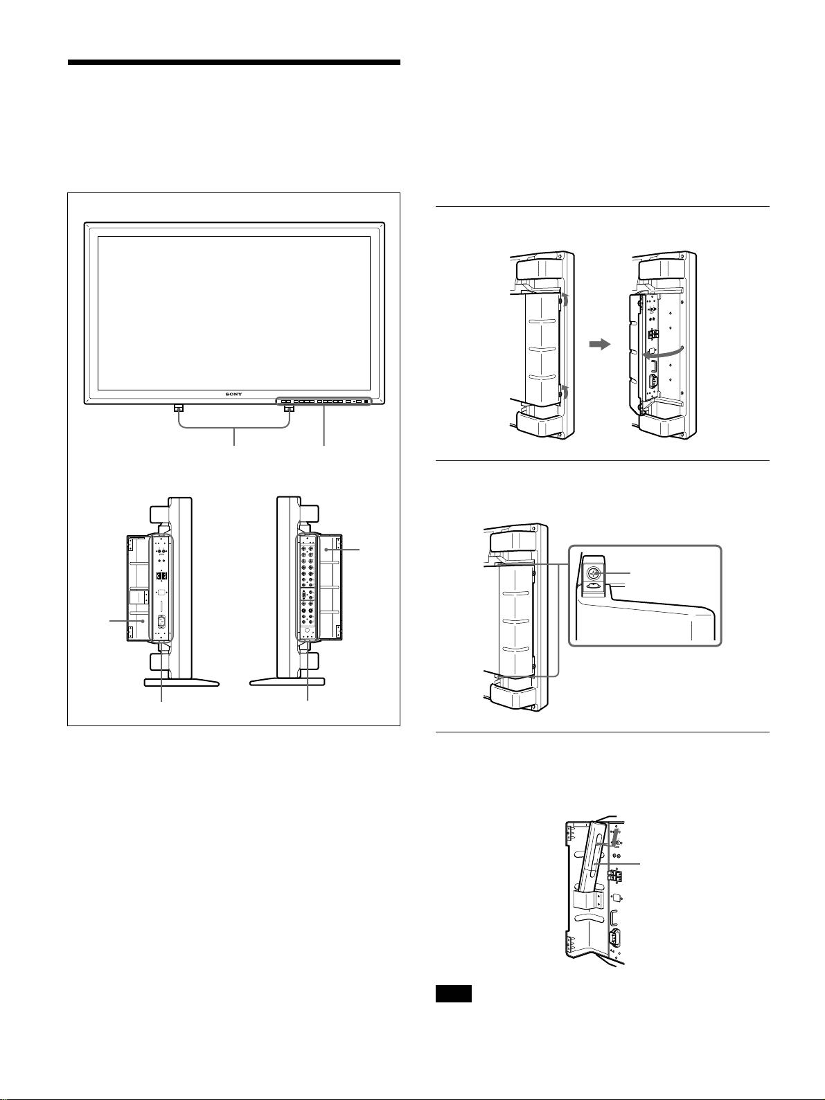
Front / Sides
5 Right connector panel
For details on the right connector panel, see “Right
Connector Panel” on page 8 (GB).
6 Right panel cover
Open it when using the right connector panel.
For details on opening the panel cover, see the below on
this page.
Front
Left side
1
Right side
To open the panel cover
Loosen the screws counterclockwise and open the cover.
2
To take off the panel cover
Loosen the screws as illustrated below and take off
the panel cover.
6
Screws
3
4
5
1 Retractable feet
Use for setting the monitor on the floor.
For details on using the retractable feet, see “Using the
Retractable Feet” on page 12 (GB).
2 Control panel
For details on the control panel, see “Control Panel” on
page 7 (GB).
3 Left panel cover
Open it when using the left connector panel.
You can install the Remote Commander in the back of
this cover.
For details on opening the panel cover, see the right on this
page.
4 Left connector panel
For details on the left connector panel, see “Left Connector
Panel” on page 10 (GB).
6 (GB)
To install the Remote Commander in the
panel cover
Install the Remote Commander in the back of the left
panel cover as illustrated below.
Remote
Commander
Note
When housing the Remote Commander, make sure
that the top of the Remote Commander faces upward
and rear faces outside.
Page 7
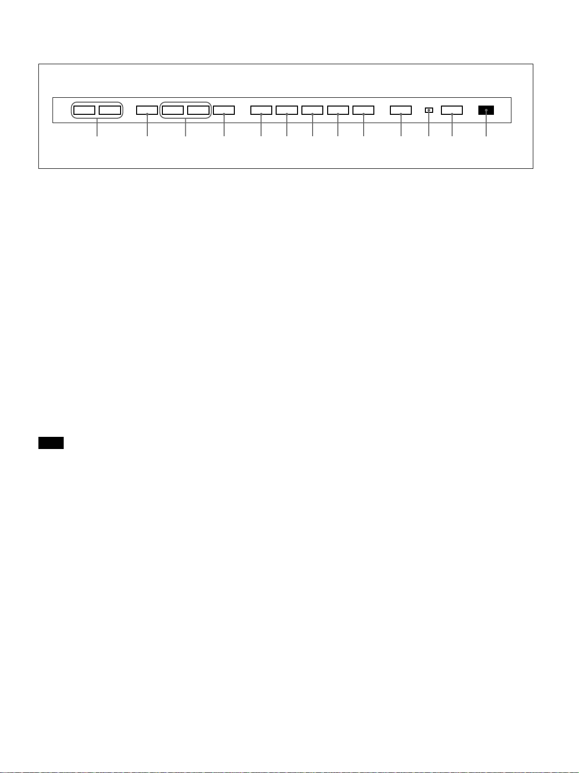
Control Panel
Location and Function of Parts and Controls
VOL – VOL + MENU ENT RGB1 YUV RGB2 LINE Y/C CTRL
qd qs qa 0 98765 4 32 1
mM
1 Remote control detector
Receives the beam from the Remote Commander.
2 1 (standby) switch/1 (standby) indicator
Press to turn the monitor on. Press again to go back to
the standby mode.
The 1 (standby) indicator lights up in red in the
standby mode.
When the 1 indicator flashes, see “Self-diagnosis
Function” on page 26 (GB).
3 Power indicator
Lights up when the monitor is turned on.
4 CTRL (control) button
To operate the buttons on the control panel, first press
this button. Then the buttons light up or flash that
show they can be operated. Press again to deactivate
them.
1
9 RGB1 button
Select the RGB signal input from the RGB1
connectors.
0 ENT (enter) button
Press to select the desired item in a menu.
qa M/m buttons
Press to move the cursor (B) to an item or to adjust
value in a menu.
qs MENU button
Press to make the menu appear.
qd VOL (volume) +/– buttons
Press the + button to increase the volume, or the –
button to decrease the volume.
Note
The buttons (except for 1 (standby) switch 2) on the
control panel do not function if you do not press the
CTRL button first.
5 Y/C button
Select the signal input from the Y/C IN jack in the
LINE connectors.
6 LINE button
Select the signal input from the VIDEO IN connector
in the LINE connectors.
7 RGB2 button
Select the signal input from the RGB2 connectors.
8 YUV button
Select the component signal input from the RGB1
connectors.
7 (GB)
Page 8
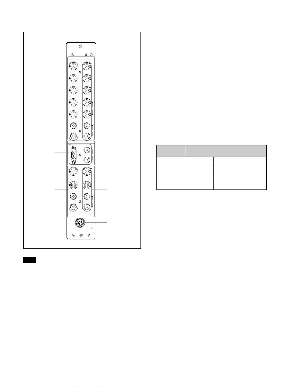
Location and Function of Parts and Controls
Right Connector Panel
RGB 1
IN OUT
R
R-Y
G
Y
B
B-Y
1
2
3
Note
The image enhancing process for video signals
(NTSC, PAL) works only for composite (Y/C) or
component (Y/R-Y/B-Y) input.
The image from the RGB input may looked blurred.
This is normal.
HD/
COMP
VD
L
R
RGB 2
RGB IN
L
R
VIDEO
Y/C
L
R
IN OUT
LINE
REMOTE
(RS-232C)
4
SYNC
AUDIO
AUDIO IN
5
AUDIO
6
1 RGB1 IN connectors
R (R-Y)/G (Y)/B (B-Y) IN (BNC-type): Input the
analog RGB signal or component signal. Connect
to the RGB signal or component (Y/B-Y/R-Y)
signal output of a computer or video equipment.
This unit also accepts the HD analog component
B/PR) signal. Input the PB signal to the B (B-
(Y/P
Y) IN connector and P
R signal to the R (R-Y) IN
connector.
HD/COMP IN (BNC-type): Input the H sync signal
or composite sync signal. Connect to the H sync
signal or composite sync signal output of a
computer or video equipment.
VD IN (BNC-type): Input the V sync signal.
Connect to the V sync signal output of a
computer or video equipment.
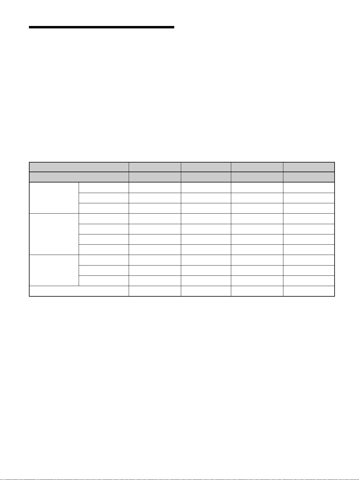
External sync signal is selected automatically. See
the priority chart below.
Input Input sync signals
connector
HD/COMP IN H Sync Comp Sync —
VD IN V Sync — —
G(Y) IN Sync on G Sync on G Sync on G
Sync signals
to be selected
H Sync Comp Sync Sync on G
V Sync
AUDIO IN (L/R) (phono type): Input the audio
signal. Connect to the audio output of a computer
or video equipment. Connect to the channel L
when the audio signal is monaural.
2 RGB2 IN connectors
RGB IN (D-sub 15-pin): Connect to the RGB signal
output of a computer.
AUDIO IN (L/R) (phono type): Input the audio
signal. Connect to the audio output of a computer.
Connect to the channel L when the audio signal is
monaural.
3 LINE IN connectors
VIDEO IN (BNC-type): Connect to the composite
video signal output of the video equipment.
Y/C IN (Mini DIN 4-pin): Connect to the Y/C
signal output of the video equipment.
AUDIO IN (L/R) (phono type): Connect to the
audio output of the video equipment. Connect to
the channel L when the audio signal is monaural.
8 (GB)
Page 9

Location and Function of Parts and Controls
4 RGB1 OUT connectors
These connectors are used as loop-through outputs of
the RGB1 IN connectors 1.
When the plug is connected to the RGB OUT
connectors, the 75-ohms termination of the RGB IN
connectors is released, and the signal input to the
RGB IN connectors is output from the these
connectors.
R (R-Y)/G (Y)/B (B-Y) OUT (BNC-type): Loop-
through outputs of the RGB IN connectors.
Connect to the RGB signal or component (Y/BY/R-Y) signal input of another monitor.
HD/COMP OUT (BNC-type): Loop-through output
of the HD/COMP IN connector. Connect to the H
sync signal or composite sync signal input of
another monitor.
VD OUT (BNC-type): Loop-through output of the
VD IN connector. Connect to the V sync signal
input of another monitor.
Note
The HD/COMP OUT and VD OUT connectors are
high impedance outputs.
When using these outputs, connect a monitor with
high impedance sync input connector, or the picture
might be oscillated or disappeared because of the
sync signal level mismatch.
6 REMOTE (RS-232C) connector (mini DIN 8pin)
This connector allows remote control of the monitor
using the RS-232C protocol. For details, see your
authorized Sony dealer.
AUDIO OUT (L/R) (phono type): Loop-through
outputs of the AUDIO IN jacks. Connect to the
audio inputs of another monitor.
5 LINE OUT connectors
These connectors are used as loop-through outputs of
the LINE IN connectors 3.
When the plug is connected to the VIDEO OUT
connector or Y/C OUT jack, the 75-oms termination
of the VIDEO IN connector or Y/C IN jack is
released, and the signal input to the VIDEO IN or Y/C
IN jack is output from the VIDEO OUT connector or
Y/C OUT jack.
VIDEO OUT (BNC-type): Connect to the
composite video signal input of another monitor
or video equipment.
Y/C OUT (Mini DIN 4-pin): Connect to the Y/C
signal input of another monitor or video
equipment.
AUDIO OUT (L/R) (phono type): Loop-through
outputs of the AUDIO IN jacks. Connect to the
audio inputs of another monitor or video
equipment.
9 (GB)
Page 10
Location and Function of Parts and Controls
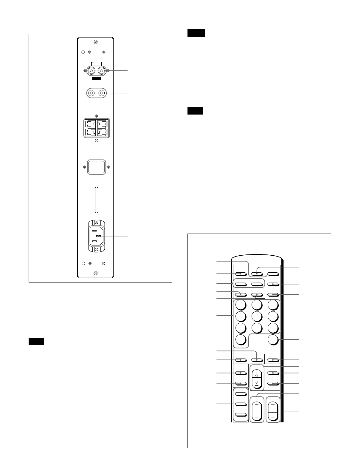
Left Connector Panel
MONITOR OUT
AUDIO
RL
VARIABLE
CONTROL S
IN
+
R–
SPEAKERS
(6-16 Ω)
SERVICE CODE
OUT
8.8.
Notes
•If you connect the CONTROL S IN jack to the other
equipment’s CONTROL S OUT jack, you cannot
operate the monitor with the Remote Commander.
•You can use the stereo cable with mini plug instead
1
2
+
L
3
–
of the control S cable.
3 SPEAKERS L/R terminals
Connect to speakers with 6 to 16 ohms impedance.
Note
Do not connect the speaker’s cord to the monitor and
to an amplifier simultaneously, or an excessive
electric current might flow from the amplifier and
damage the monitor.
4 SERVICE CODE indicator
4
The indicator is only for qualified personnel.
5 -AC IN socket
Connect the supplied AC power cord to this socket
and to a wall outlet. Once you connect the AC power
cord, the monitor turns to standby mode.
5
AC IN
1 MONITOR OUT AUDIO (L/R) jacks (phono
type)
Output the signal input from the AUDIO IN jacks.
Connect to the audio inputs of an audio amplifier (not
supplied).
Note
These jacks are variable outputs. Set the volume to
maximum position to set the output level to
500 mVrms.
2 CONTROL S IN/OUT jacks (mini jacks)
Connect to the CONTROL S jacks of video
equipment or another monitors. Then you can
simultaneously control all equipment with a single
Remote Commander.
To control equipment by aiming the supplied Remote
Commander to the remote control detector of the
monitor, connect the CONTROL S OUT jack of the
monitor and the CONTROL S IN jack of other
equipment.
Remote Commander RM-921
1
DISPLAY
RGB2
Y/C
2
5
8
ZOOM
SELECT
VOL
POWER
YUV
MTS/MPX
3
6
9
CH
DEGAUSS
MENU
ENTER
CH
2
3
4
5
6
7
8
9
0
qa
MUTING
RGB1
LINE
1
4
7
10/0
STILL
POWER
ON
OFF
ON
SET
OFF
ID MODE
qs
qd
qf
qg
qh
qj
qk
ql»
w;…
wa
10 (GB)
Page 11

Location and Function of Parts and Controls
1 POWER switch
Press to turn on the monitor. Press again to go back to
the standby mode.
Note
When using multiple monitors, press this switch to
turn monitors which are already on into the standby
mode, or turn on monitors which are in the standby
mode.
2 MUTING button
Press to mute the sound. Press this button again or
press the VOL (volume) +/– button to obtain the
sound again.
3 RGB1/RGB2 buttons
Select the signal input from the RGB1 or RGB2
connectors.
4 LINE button
Selects the signal input from the VIDEO IN connector
in the LINE connectors.
5 Y/C button
Selects the signal input from the Y/C IN jack in the
LINE connectors.
qs DISPLAY button
Displays the input signal information on the top of the
monitor screen. Press again to clear it.
qd YUV button
Selects the component signal input from the RGB1
connectors.
qf MTS/MPX button
This button does not operate with the monitor.
qg CH button
This button does not operate with the monitor.
qh DEGAUSS button
This button does not operate with the monitor.
qj SELECT +M/–m buttons
Press to move the cursor (B) to an item or to adjust
value in a menu.
qk MENU button
Press to make the menu appear.
ql ENTER button
Press to select the desired item in a menu.
6 Number buttons
Press to select the index number.
7 ZOOM button
This button does not operate with the monitor.
8 STILL button
This button does not operate with the monitor.
9 POWER ON switch
Press to turn on the monitor. When you use multiple
monitors, you can use this switch instead of the
POWER switch 1 not to affect another monitor
which is already turned on.
0 POWER OFF switch
Press to turn the monitor into the standby mode. When
you use multiple monitors, you can use this switch
instead of the POWER switch 1 not to affect another
monitor which are in the standby mode.
qa ID MODE (ON/SET/OFF) buttons
Press the ON button to make an index number appear
on the screen. Then press the index number of the
monitor you want to operate and press the SET button.
After you finish the operation, press the OFF button to
return to the normal mode.
w; VOL +/– buttons
Press the + button to increase the volume, or the –
button to decrease the volume.
wa CH +/– buttons
This button does not operate with the monitor.
11 (GB)
Page 12
Location and Function of Parts and Controls / Installation
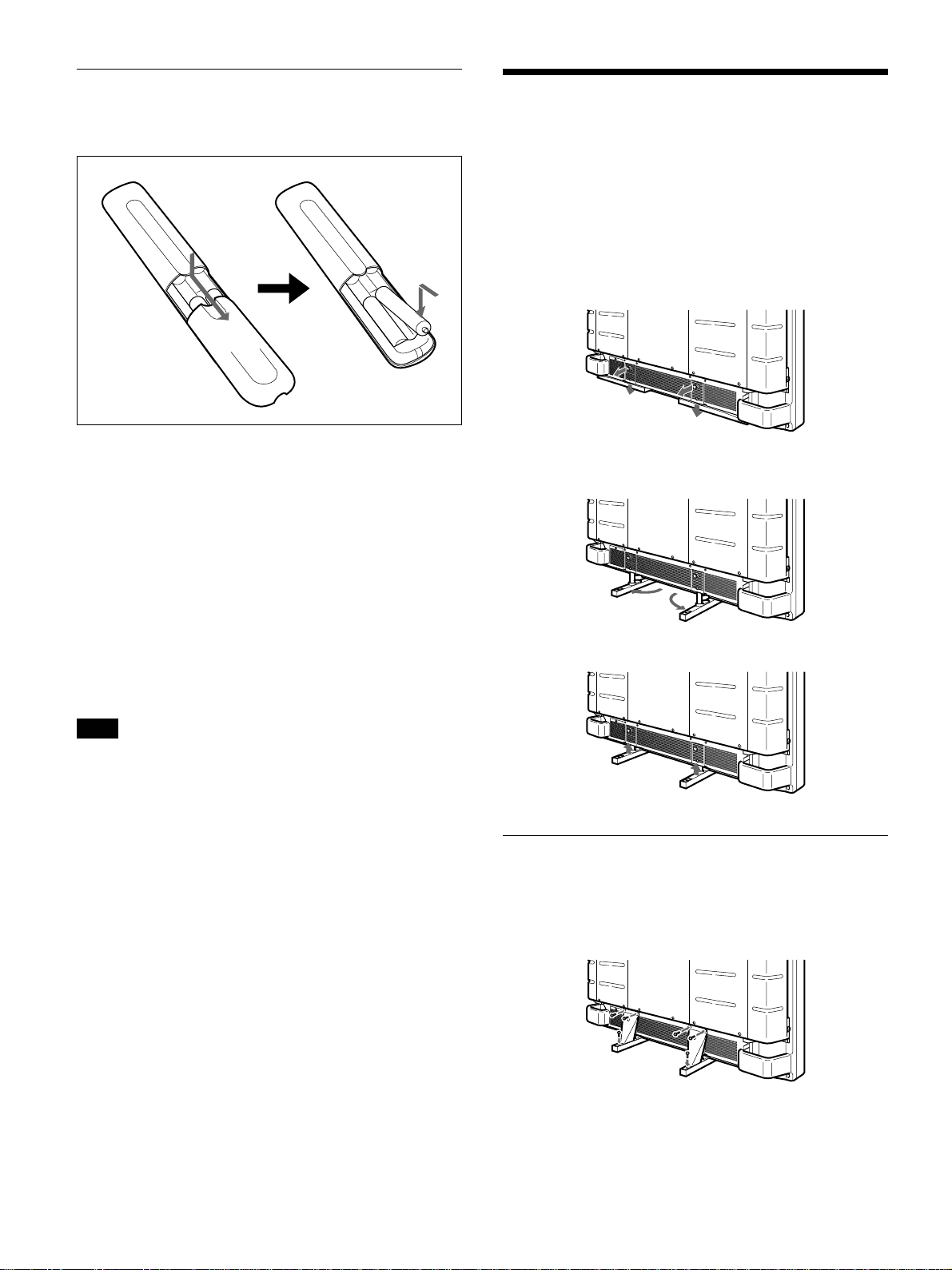
Installing batteries
Insert two size AA (R6) batteries in correct polarity.
Installation
Using the Retractable Feet
Be sure to
install the
negative <
end first.
E
e
•In normal operation, batteries will last up to half a
year. If the Remote Commander does not operate
properly, the batteries might be exhausted. Replace
them with new ones.
•To avoid damage from possible battery leakage,
remove the batteries if you do not plan to use the
Remote Commander for a fairly long time.
When the Remote Commander does not work
Check that the 1 indicator lights up. The Remote
Commander operates the monitor only when the
monitor is turned on, or it is in the standby mode.
–
e
E
This section describes the installation arrangements
for installing the projector.
1 Pull out the knobs and pull down the retractable
feet.
2 Turn the retractable feet outward.
3 Push in the retractable feet and lock.
Note
If you connect the cable to the CONTROL S IN jack
on the side of the monitor, you cannot operate the
monitor with the Remote Commander.
To fix the retractable feet
When the unit is installed on the floor, be sure to fix
the retractable feet.
Install the foot support brackets as illustrated below.
12 (GB)
Page 13
Installation
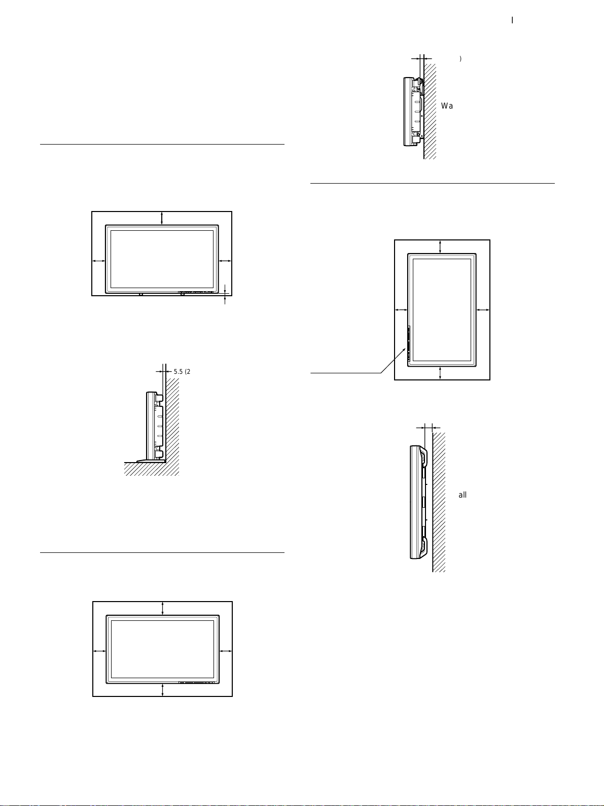
Caution
•When you install the monitor, make sure there is
more space than that shown in the figure below.
•The ambient temperature must be 0°C – +35°C
(32°F – 95°F).
When using the retractable feet
Front
Wall
20 (7 7/8)
Side
10
Wall Wall
(4)
Floor
5.5 (2 1/4)
10
(4)
2.5 (1)
Side
3.5 (1 7/8)
Wall
Hooked on the wall: Vertically
Front
Wall
10 (4)
20
(7 7/8)
Make sure that
the control
section is at the
bottom.
10 (4)
Wall
Units: cm (inches)
25
(9 7/8)
WallWall
Wall
Floor
Units: cm (inches)
When using the mounting bracket
Front
Wall
25 (9 7/8)
10
Wall Wall
(4)
7
25 (9
/8)
Wall
10
(4)
Side
5 (2)
Wall
Units: cm (inches)
13 (GB)
Page 14
Connections
Connections
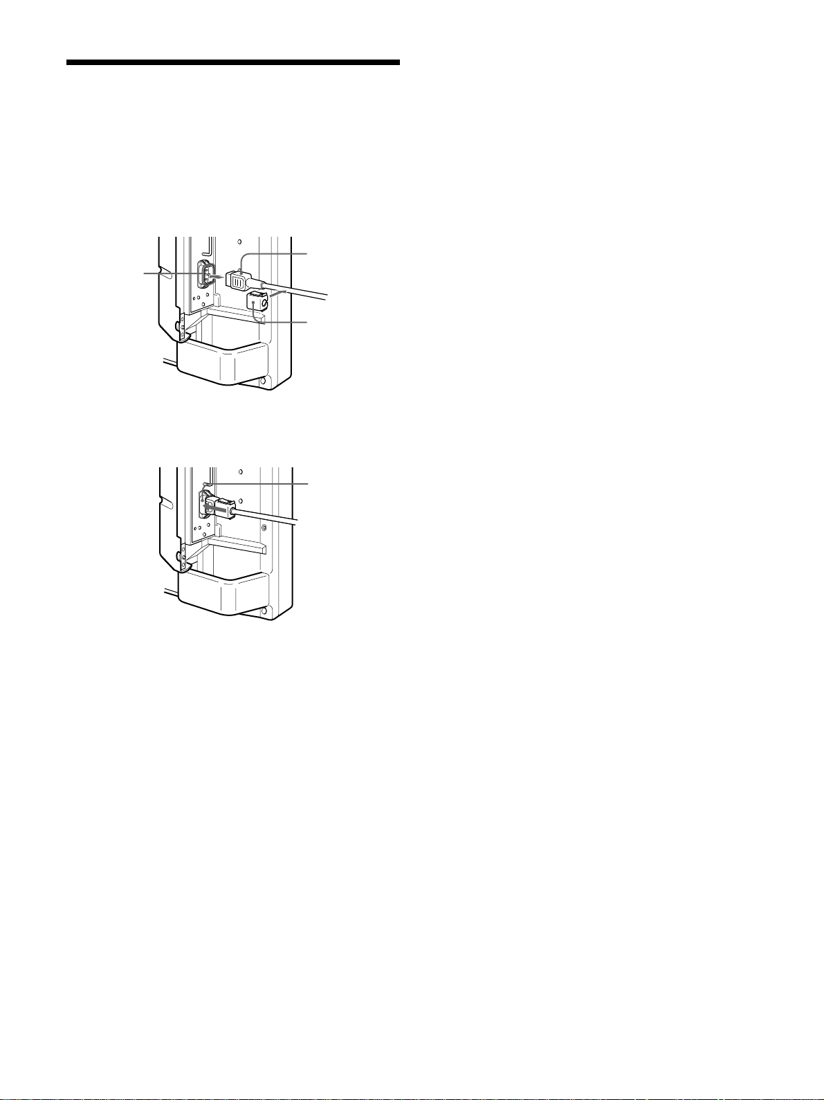
Connecting the AC Power Cord
1 Plug the power cord into the AC IN socket. Then,
attach the AC plug holder (supplied) to the AC
power cord.
AC power
AC IN
socket
2 Slide the AC plug holder over the cord until it
connects to the AC IN socket cover.
cord
AC plug
holder
AC IN
socket
cover
To remove the AC power cord
Squeeze the upper and lower sides and pull out the
AC plug holder.
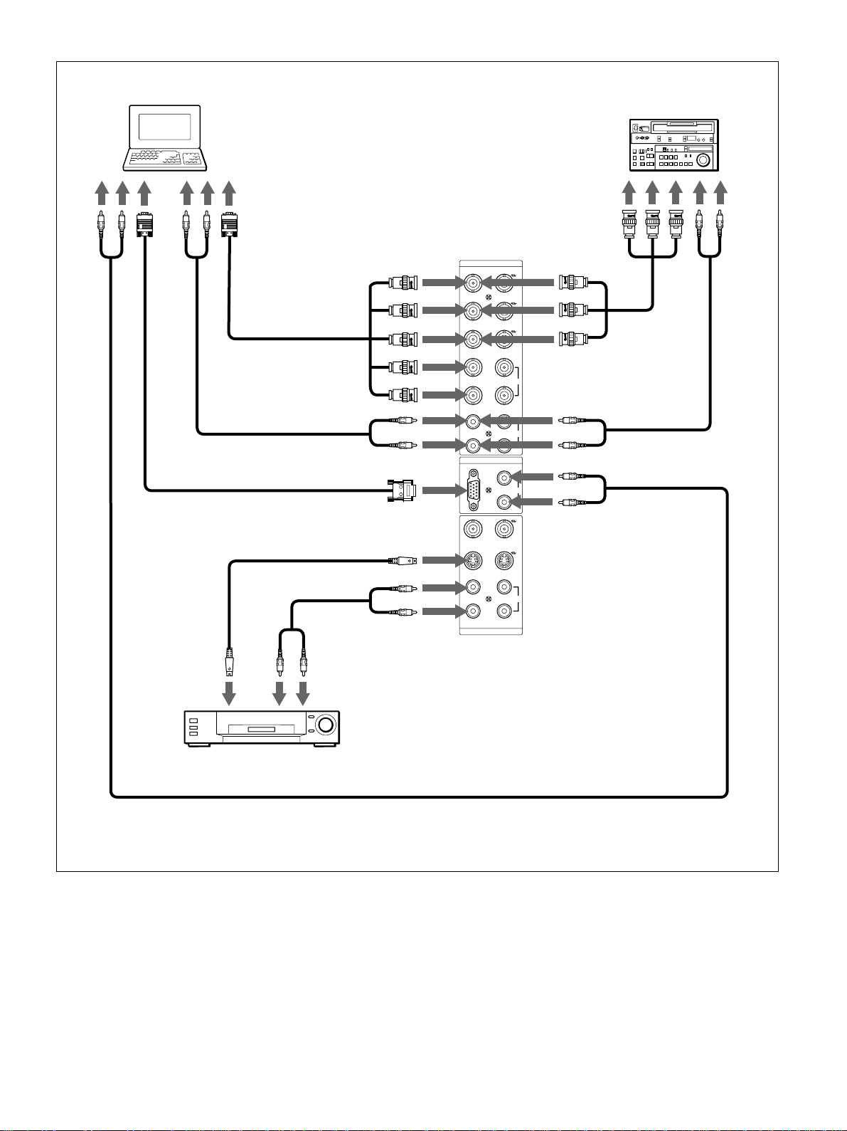
Connection Example
Before you get started
•First make sure that the power to each piece of
equipment is turned off.
•Use connecting cables suitable for the equipment to
be connected.
•The cable connectors should be fully inserted into
the jacks. A loose connection may cause hum and
other noise.
•To disconnect the cable, pull out by grasping the
plug. Never pull the cable itself.
•Read the instruction manual of the equipment to be
connected.
14 (GB)
Page 15
Connections
to audio
output
Computer
to video
output
to audio
output
to video
output
* to R(R-Y)/G(Y)/
B(B-Y), HD/COMP,
VD IN
to AUDIO IN
to RGB IN
to Y/C or
VIDEO IN
RGB 1
IN OUT
R-Y
B-Y
HD/
COMP
VD
RGB 2
RGB IN
VIDEO
Y/C
Betacam SP video
cassette recorder
to component
signal output
R
G
Y
B
to audio
output
* to R(R-Y)/G(Y)/
SYNC
B(B-Y) IN
to AUDIO IN
L
AUDIO
R
L
AUDIO IN
R
to AUDIO IN
to video
output
VCR, laser disc player, game
machine, etc.
* cannot be used at the same time.
to audio
output
to AUDIO IN
L
R
IN OUT
LINE
AUDIO
15 (GB)
Page 16
Using On-screen Menus
Using On-screen Menus
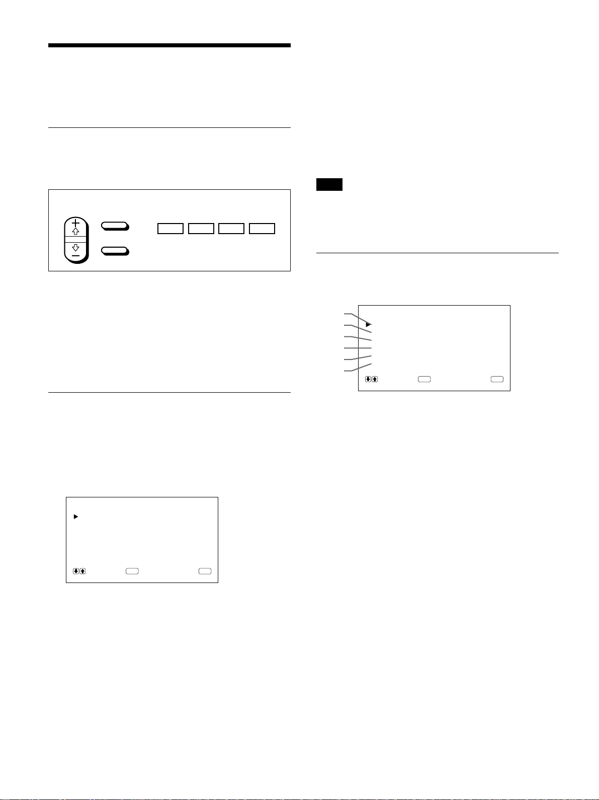
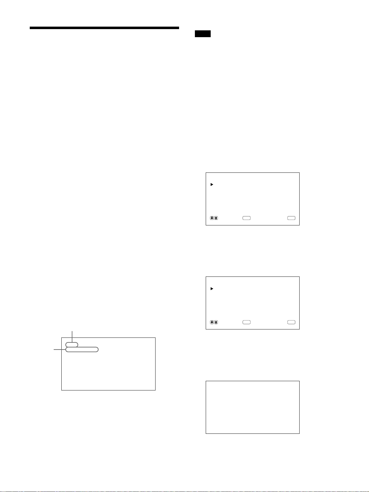
Operating Through Menus
Menu operating buttons
4 Press M/m to adjust or select the setting and press
ENT to set.
The setting is registered and the menu returns to
the previous menu.
To return to the normal screen, press the MENU
button repeatedly until the menu disappears.
There are four buttons on the monitor and the Remote
Commander for menu operations.
Remote Commander Monitor
SELECT
MENU
ENTER
MENU ENT
m
M
The buttons on the control panel are used for
explanation purpose in this operating instructions.
The ENTER button on the Remote Commander has
the same function as the ENT button on the control
panel and the SELECT +M/–m buttons on the Remote
Commander as same as the M/m buttons on the
control panel.
Configuration of the menu
To select the language used in the menu, see page
26 (GB).
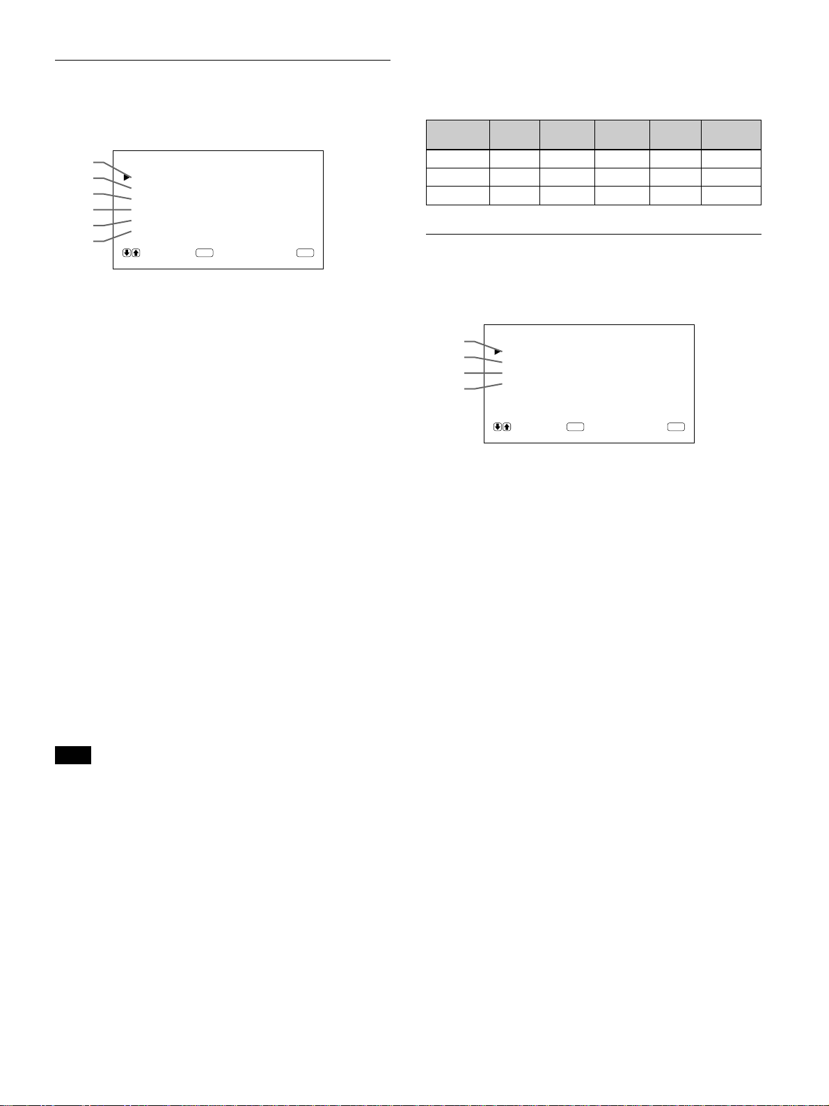
Menu Guide
Note
“– – – –” appears next to an item when its function is
not available. The availability depends on the types of
input signal.
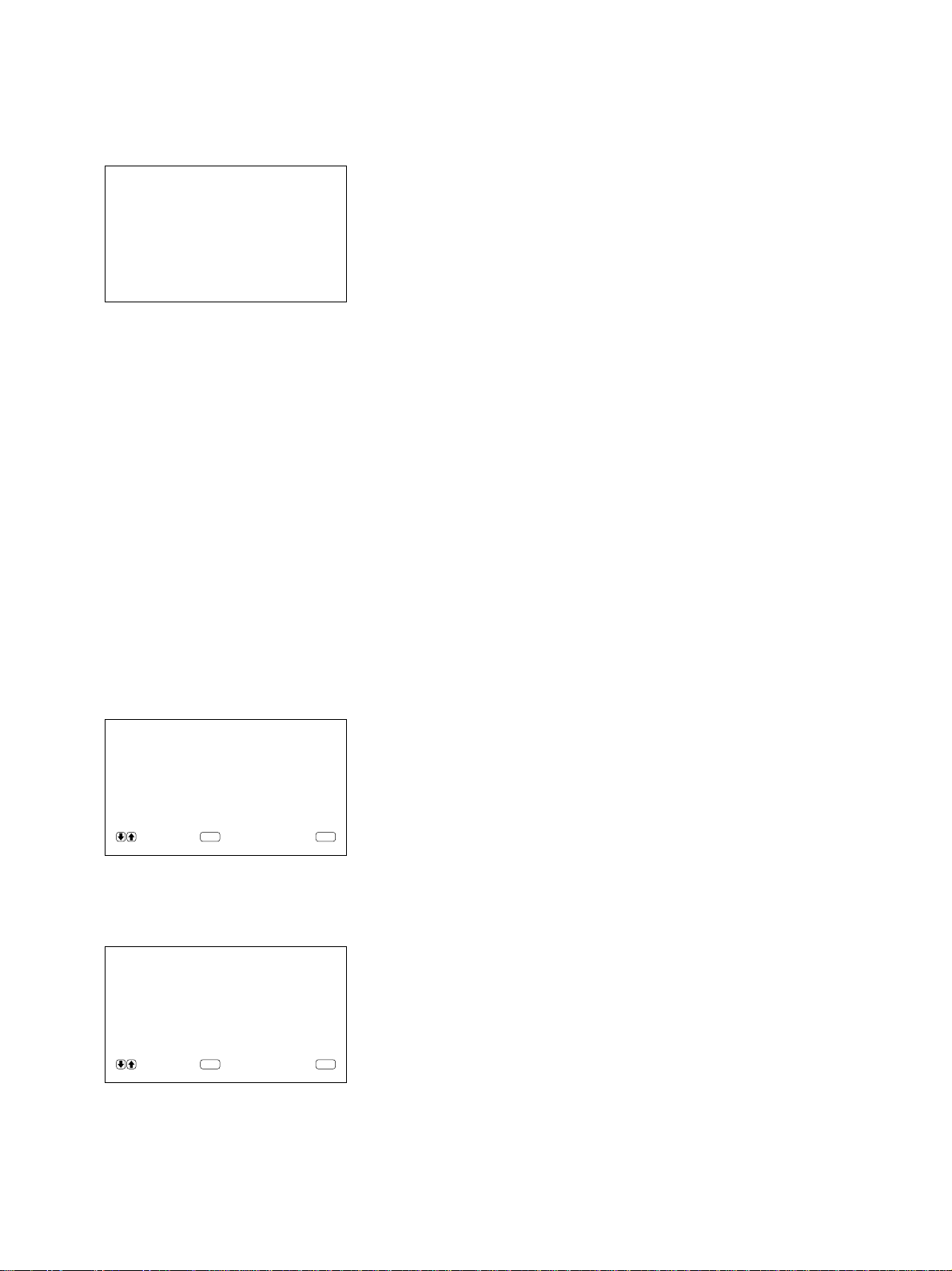
PIC CONTROL menu
This menu is used for adjusting the picture.
1
2
3
4
5
6
1 CONTRAST
Press M to increase the contrast and press m to
decrease it.
PIC CONTROL
CONTRAST : 80
BRIGHTNESS : 00
CHROMA : 0 0
PHASE : 00
COLOR TEMP :H IGH
RESET
SELECT CANCEL
ENTER
MENU
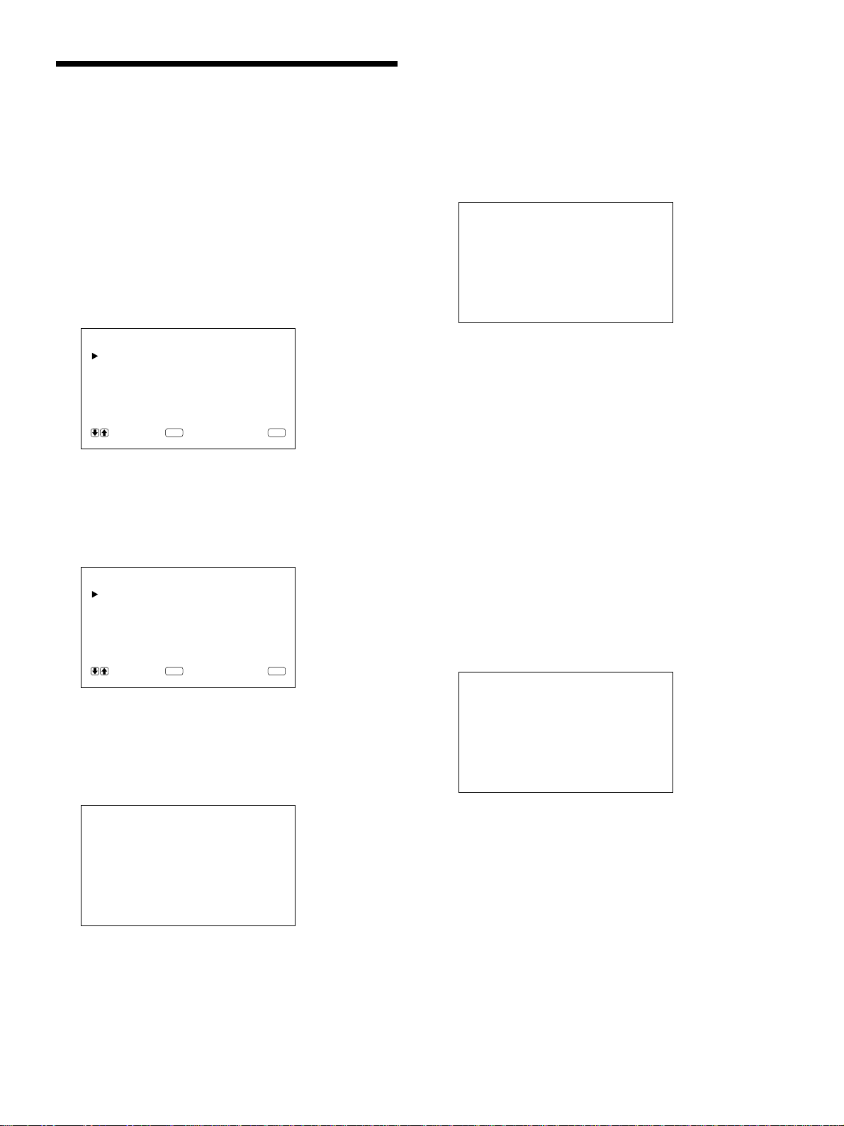
1 Press MENU.
The main menu appears on the monitor screen.
MA IN MENU
PIC CONTROL
PIC SIZE
CONF I G
MEMORY
REMOTE
STATUS
SELECT CANCEL
ENTER
MENU
2 Press M/m to move the cursor (B) and press ENT
to select a menu.
The selected menu appears on the monitor screen.
3 Press M/m to move the cursor (B) and press ENT
to select an item.
The menu for the selected item appears on the
monitor screen.
2 BRIGHTNESS
Press M to make the picture brighter and press m to
make it darker.
3 CHROMA
Press M to increase color saturation and press m to
decrease it.
4 PHASE
Press M to make overall picture greenish and press m
to make it purplish.
5 COLOR TEMP
Select a color temperature from HIGH or LOW.
6 RESET
Select to restore the factory settings in the PIC
CONTROL menu items 1 to 5.
For details on using the reset function, see “Restoring the
PIC CONTROL Menu Items to Original Settings” on page
22 (GB).
16 (GB)
Page 17
Using On-screen Menus
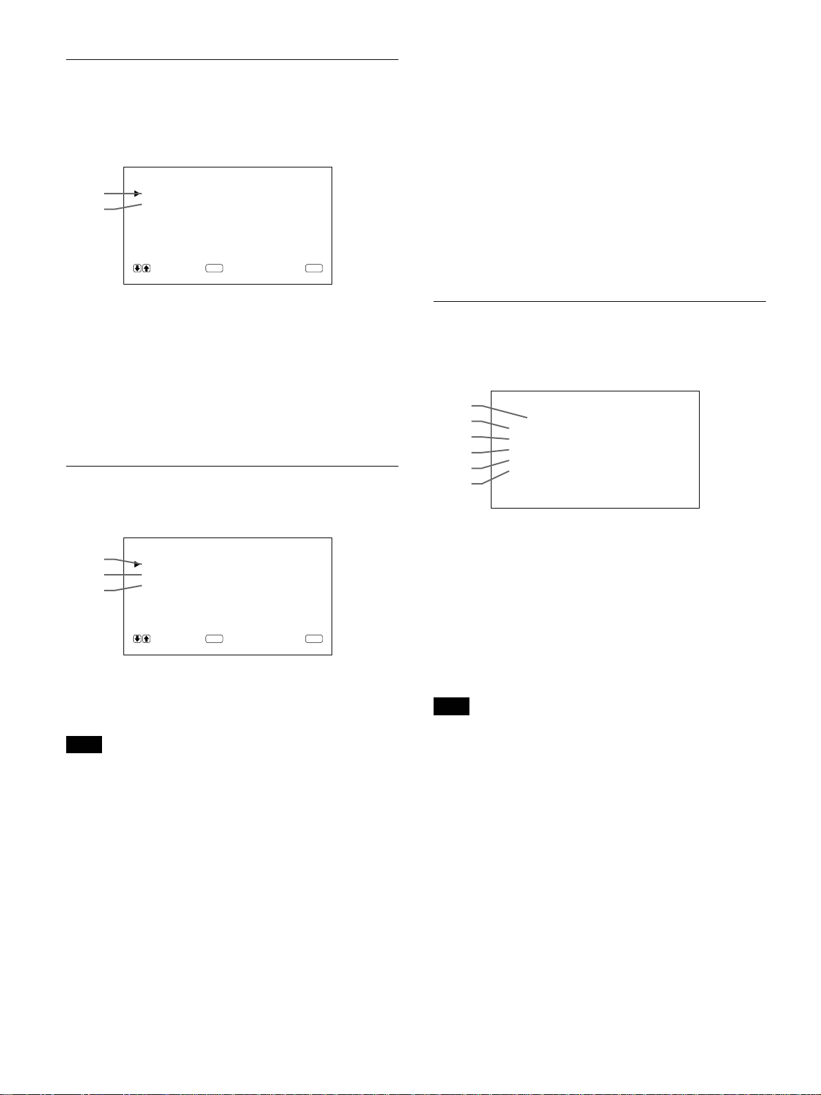
PIC SIZE menu
This menu is used for positioning and resizing the
picture.
7
8
9
0
qa
qs
7 H SIZE
Adjusts the horizontal picture size. Press M to enlarge
the horizontal size and press m to diminish it.
8 H SHIFT
Adjusts the horizontal centering. Press M to move the
picture to the right and press m to move it to the left.
9 V SIZE
Adjusts the vertical picture size. Press M to enlarge
the vertical size and press m to diminish it.
q; V SHIFT
Adjusts the vertical centering. Press M to move the
picture up and press m to move it down.
qa ASPECT
Set the aspect ratio of the picture to 4:3 or 16:9.
qs RESET
Select to restore the factory settings in the PIC SIZE
menu items 7 to qa.
For details on using the reset function, see “Restoring the
Original Picture Size and Position” on page 24 (GB).
Note
When receiving DTV signals and changing the H/V
SIZE or H/V SHIFT in the PIC SIZE menu, the
system goes into the Offset Sampling Mode; the
image may become blurred or horizontal lines may
appear because the memory write phase is faster than
the read phase. This is not a system malfunction.
To avoid this problem, reset the H/V SIZE and the H/
V SHIFT to the factory settings. If any problems
persist with the factory setting, adjust the settings as
shown below.
To adjust the setting, see “Restoring the original
Picture Size and Position” (page 24 (GB)).
PIC SIZE
HSIZE : 00
HSHIFT : 00
VSIZE : 00
VSHIFT : 00
ASPECT : 4x3
RESET
SELECT CANCEL
ENTER
MENU
•DTV signals for factory setting:
1080/60i, 480/60i, 575/50i, 480/60p
•Other DTV signals and their recommended settings:
HVHV
SIZE SIZE SHIFT SHIFT
1080/50i + 48 + 11 + 10 – 02 16:9
1080/48i MAX + 09 + 12 – 02 16:9
1152/50i + 33 – 02 + 20 0 16:9
ASPECT
CONFIG menu
This menu is used for adjusting the signal or selecting
the language.
qd
qf
qg
qh
qd ENHANCE (Sharpness)
You can change the outline correction level:
LOW: Default setting for VIDEO signal
HIGH: Default setting for computer signal
qf H FILTER
Select AUTO normally.
Select HIGH when the ringing appears on the screen.
Select LOW when the moiré pattern or noise appears
on the screen. The moiré pattern or noise decreases
even the screen looks a little blurred.
qg DISPLAY
Select ON to display the input signal information for
about five seconds on the top of the monitor screen
when turning on the power or switching the input
signal.
qh LANGUAGE
Select the on-screen language among five languages.
Available languages are: English, German, French,
Italian and Spanish.
For details on selecting the language, see “Selecting the
On-screen Language” on page 26 (GB).
CONF I G
ENHANCE :HIGH
H FI LTER :AUTO
DISPLAY : ON
LANGUAGE
SELECT CANCEL
ENTER
MENU
17 (GB)
Page 18
Using On-screen Menus
MEMORY menu
This menu is used for saving or recalling the settings
in the PIC CONTROL, PIC SIZE and CONFIG (only
for ENHANCE and H FILTER) menus.
MEMORY
qj
qk
LOAD
SAVE
SELECT CANCEL
ENTER
MENU
For details, see “Using the Memory” on page 25 (GB).
qj LOAD
Recalls the preset settings.
qk SAVE
Saves the settings.
REMOTE menu
wa REMOTE ONLY
Select ON to disable the front control buttons on the
monitor. The monitor can only be controlled with the
Remote Commander. While REMOTE ONLY is ON,
the indicators on the front panel go off.
To cancel the REMOTE ONLY mode, set REMOTE
ONLY to OFF with the Remote Commander, or press
the CTRL button while pressing the 1 switch. The
monitor turns to the standby mode and the REMOTE
ONLY mode is canceled.
The setting in this item is still retained when the AC
power cord is disconnected.
STATUS menu
This menu is used for displaying the internal condition
of the monitor.
ws
wd
wf
wg
wh
wj
STATUS
[ PFM-510A1WU ]
SERIAL No. : 2000001
OPERATION :000000H
SOFTWARE :
TEMPERATURE : OK
FAN : OK
Ver
1.00
This menu is used for the remote control setting.
ql
w;
wa
REMOTE
INDEX NO. : 001
REMOT E MODE : TV
REMOTE ONLY : OFF
SELECT CANCEL
ENTER
MENU
ql INDEX NO.
Sets the index number of the monitor.
Note
When you set the number, use the buttons on the
monitor.
For details on the index number, see “Operating a Specific
Monitor With the Remote Commander” on page 27 (GB).
w; REMOTE MODE
Select the Remote Commander mode.
TV: Sony monitors’ or TVs’ commander
PJ: Sony projectors’ commander
OFF: Disables the remote control.
For details, see “Using the Other Remote Commander” on
page 28 (GB).
ws Model name
Indicates the model name.
wd SERIAL No.
Indicates the serial number.
wf OPERATION
Indicates the total operation hours.
Note
The standby mode is not counted as OPERATION
time.
wg SOFTWARE
Indicates the system software version.
wh TEMPERATURE
Indicates whether the internal temperature of the
monitor is usual.
OK: Usual
NG: Unusual
When the internal temperature is unusual, NG is
displayed and the item flashes in red. The 1 indicator
on the control panel also flashes.
18 (GB)
Page 19
Note
The “TEMPERATURE NG” message may appear
when the ventilation holes are blocked or the monitor
is installed in a poorly ventilated area. In this case,
check that the ventilation holes are not blocked and
install the monitor in a good ventilated area. If the
message still displayed, contact your authorized Sony
dealer.
When the 1 indicator flashes or NG indicates, see “Selfdiagnosis Function” on page 26 (GB).
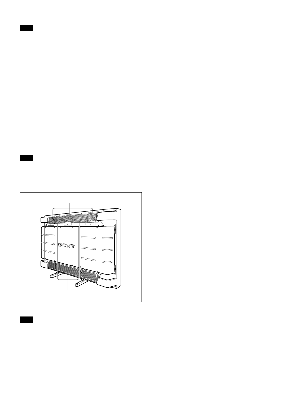
wj FAN
The cooling fans are built in this monitor. This item
indicates whether the cooling fans work properly.
OK: Usual
NG: Unusual
When the cooling fans are unusual, NG is displayed
and the item flashes in red. The 1 indicator on the
control panel also flashes.
Using On-screen Menus
Note
When the “FAN NG” message appears, contact your
authorized Sony dealer.
When the 1 indicator flashes or NG indicates, see “Selfdiagnosis Function” on page 26 (GB).
Cooling fans
Ventilation holes
Note
The upper cooling fans detect the monitor’s internal
temperature and control the fans rotations. If the
ambient temperature is high, the number of fan
rotations increase and the noise will be louder.
19 (GB)
Page 20
Watching the Picture
Watching the Picture
Before you start
•Turn on the monitor.
•Turn on the connected equipment and play a video
source.
•To display the input signal information on the screen
when turning on the power or switching the input
signal, set “DISPLAY” in the CONFIG menu to ON.
•To select the on-screen language used in the menu,
see page 26 (GB).
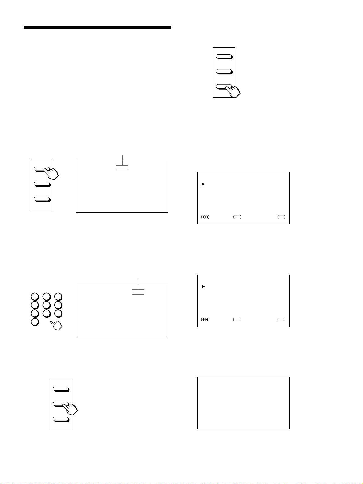
Switching the Picture
1 Press CTRL on the control panel of the monitor.
RGB1, YUV, RGB2, LINE, and Y/C buttons light
up.
2 Select the input source to be displayed by pressing
the following buttons.
RGB1:Selects the audio and video signal input
from the RGB1 connectors when the input
signal is RGB signal.
YUV: Selects the audio and video signal input
from the RGB1 connectors when the input
signal is component signal.
RGB2:Selects the audio and video signal input
from the RGB2 connectors.
LINE: Selects the audio and video signal input
from the VIDEO IN connector and
AUDIO IN jack in the LINE connectors.
Y/C: Selects the audio and video signal input
from the Y/C IN connector and AUDIO
IN jack in the LINE connectors.
Color system or horizontal/vertical frequency
Note
We recommend the input source video equipment
equipped with the TBC (time base corrector). If you
receive the signal without the TBC, the picture may
disappear due to disturbance of the sync signal.
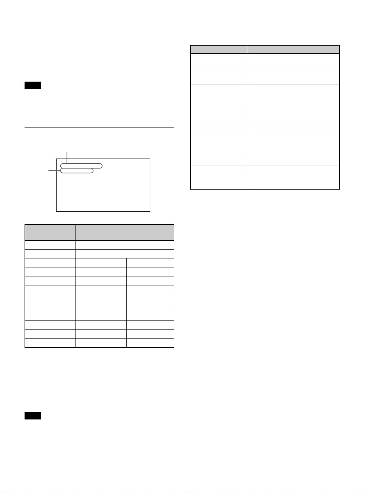
Input Signal and Monitor Status Information Display
Input signal and monitor status information is
displayed on-screen for about five seconds when
turning on the power or switching the input signal.
To disable this function, follow the steps below.
1 Press MENU.
The main menu appears on the monitor screen.
MA IN MENU
PIC CONTROL
PIC SIZE
CONF I G
MEMORY
REMOTE
STATUS
SELECT CANCEL
ENTER
MENU
2 Press M/m to move the cursor (B) to “CONFIG”
and press ENT.
The CONFIG menu appears on the monitor
screen.
CONF I G
ENHANCE :HIGH
H F ILTER :AUTO
DISPLAY : ON
LANGUAGE
SELECT CANCEL
ENTER
MENU
Signal
type
PAL
LINE·Y/C
The selected input signal appears on the monitor
screen.
You can also switch the input signal from the
Remote Commander.
20 (GB)
3 Press M/m to move the cursor (B) to “DISPLAY”
and press ENT.
The following menu appears on the monitor
screen.
DISPLAY : ON
Page 21
Watching the Picture
4 Press M to set “DISPLAY” to OFF and press
ENT.
The DISPLAY function is disabled.
To activate the information function, set “DISPLAY”
to ON at the step 4 above.
Note
You can display the input signal information anytime
by pressing the DISPLAY button on the Remote
Commander, regardless of the above setting.
The input signal information list
Color system or horizontal/vertical frequency
31.5
kHz
/60
Signal
type
RGB1 ·RGB
Hz
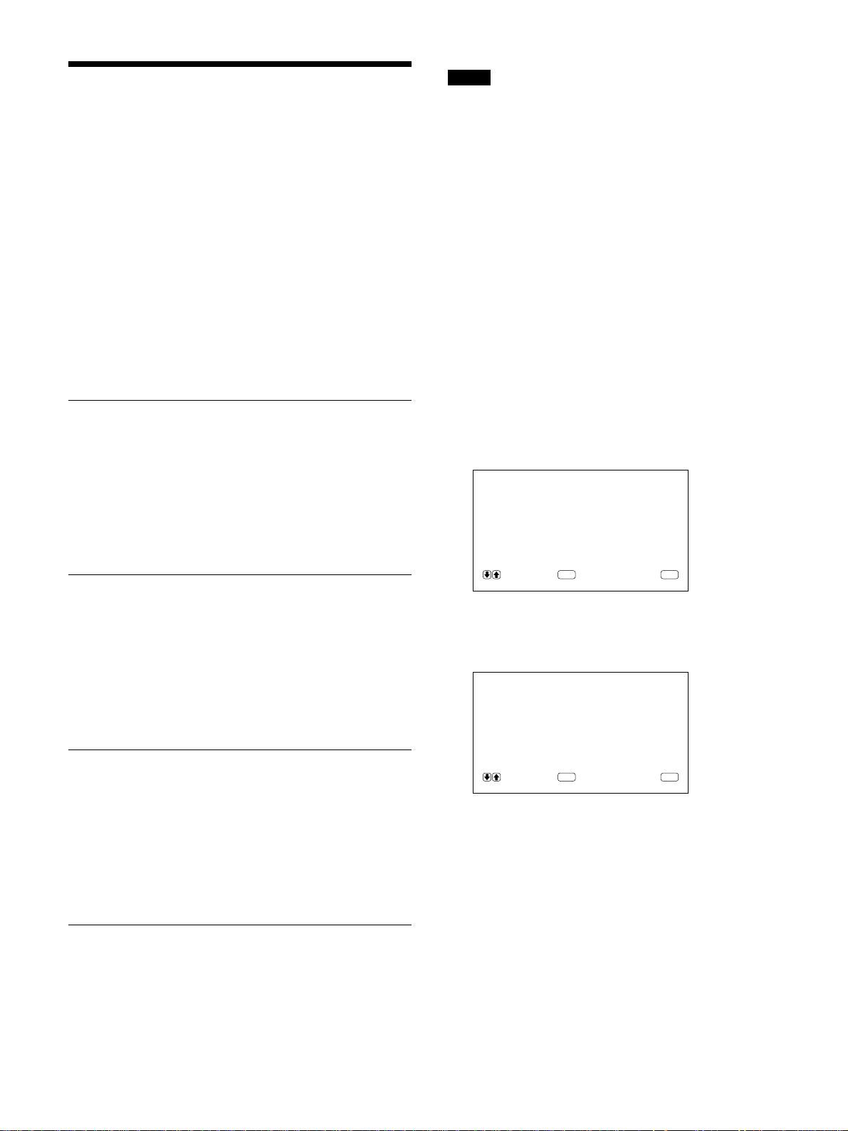
Actual on-screen display of the monitor status
On-screen display Significance
31.5kHz / 60Hz (eg.) The selected input signal is
computer RGB.
525 / 60 (eg.) The selected input signal is RGB or
component video.
NTSC The selected input signal is NTSC.
PAL The selected input signal is PAL.
OTHERS The input signal is out of the
capture range.
NO SYNC There is no input signal.
MUTING The sound is muted.
RGB1 RGB The signal mode of RGB1 is set to
RGB.
RGB1 YUV The signal mode of RGB1 is set to
component video.
LINE COMP Composite video input is selected at
LINE.
LINE Y/C Y/C video input is selected at LINE.
Input signal Color system or horizontal/vertical
NTSC NTSC
PAL PAL
VGAa) (Graphics) 31.5 kHz 60 Hz
VGA (Text) 31.5 kHz 70 Hz
HDTV 33.8 kHz 60 Hz
Macb) 13" 35.0 kHz 67 Hz
VESAc) 800×600 37.9 kHz 60 Hz
VESA 1024×768 48.4 kHz 60 Hz
Mac 16" 49.7 kHz 75 Hz
ATId) 1280×1024 64.0 kHz 60 Hz
Mac 21" 68.7 kHz 75 Hz
VESA 1280×1024 80.0 kHz 75 Hz
frequency display
a) VGA is a registered trademark of the International
Business Machines Corporation, USA.
b) Mac (Macintosh) is a registered trademark of Apple
Computer, Inc.
c) VESA is a registered trademark of Video Electronics
Standard Association.
d) ATI is a registered trademark of ATI Technologies, Inc.
Note
When inputting the HDTV signal, input the tri-level
sync signal to the G/Y IN connector.
21 (GB)
Page 22
Adjusting the Picture
Adjusting the Picture
While watching the picture, you can adjust contrast,
brightness, chroma, and phase to suit your taste. The
adjustments can be carried out for each input signal
separately. You can also store the adjusted levels in
memory.
Adjusting the Contrast, Brightness, Chroma, and Phase
Press MENU so that the main menu appears on the
monitor screen and select the “CONTRAST”,
“BRIGHTNESS”, “CHROMA”, or “PHASE” from
the PIC CONTROL menu with the M/m buttons.
CONTRAST
Select the “CONTRAST” with the M/m buttons and
press the ENT button.
Adjust the contrast with the M/m buttons in the range
from MIN (0) to MAX (+100).
M: to increase picture contrast
m: to decrease picture contrast
Notes
•CHROMA and PHASE controls do not function with
RGB signal.
•PHASE control does not function with component
signal.
•PHASE control does not function with PAL color
source.
•Do not change the CHROMA/PHASE (NTSC only)
level when the selected signal is not NTSC or PAL.
Although it gives no effect to the current picture, it
does affect the picture of the NTSC or PAL signal
which is input later.
Restoring the PIC CONTROL Menu Items to Original Settings
1 In the PIC CONTROL menu, Press M/m to move
the cursor (B) to “RESET” and press ENT.
The following menu appears on the monitor
screen.
RESET : NO
BRIGHTNESS
Select the “BRIGHTNESS” with the M/m buttons and
press the ENT button.
Adjust the brightness with the M/m buttons in the
range from MIN (–50) to MAX (+50).
M: to make overall picture greenish
m: to make overall picture purplish
CHROMA
Select the “CHROMA” with the M/m buttons and
press the ENT button.
Adjust the chroma with the M/m buttons in the range
from MIN (–50) to MAX (+50).
M: to increase color intensity
m: to decrease color intensity
PHASE
Select the “PHASE” with the M/m buttons and press
the ENT button.
Adjust the phase with the M/m buttons in the range
from MIN (–50) to MAX (+50).
M: to make overall picture greenish
m: to make overall picture purplish
SELECT CANCEL
ENTER
MENU
2 Press M/m.
“NO” changes to “YES”.
RESET : YES
SELECT CANCEL
ENTER
MENU
3 Press ENT.
The PIC CONTROL menu items are restored.
To cancel the reset function, press the MENU button
before pressing the ENT button.
22 (GB)
Page 23
Resizing and Positioning
Resizing and Positioning the Picture
5 Press ENT.
The menu returns to the PIC SIZE menu.
the Picture
You can shift the position of the picture so that it fits
in the screen, or adjust the vertical and horizontal size
of the picture separately.
Resizing the Picture
1 Press MENU.
The main menu appears on the monitor screen.
MA IN MENU
PIC CONTROL
PIC SIZE
CONF I G
MEMORY
REMOTE
STATUS
SELECT CANCEL
ENTER
2 Press M/m to move the cursor (B) to “PIC SIZE”
and press ENT.
The PIC SIZE menu appears on the monitor
screen.
MENU
6 Press M/m to move the cursor (B) to “V SIZE”
and press ENT.
The following menu appears on the monitor
screen.
VSIZE : 00
7 Press M/m to resize the picture.
M: to expand vertical size
m: to reduce vertical size
The vertical picture size is indicated on the
monitor screen from MIN(–50) to MAX(+50).
The factory value is 00.
8 Press ENT.
The menu returns to the PIC SIZE menu.
Adjusting the Picture P osition
PIC SIZE
HSIZE : 00
HSHIFT : 00
VSIZE : 00
VSHIFT : 00
ASPECT : 4x3
RESET
SELECT CANCEL
ENTER
MENU
3 Press M/m to move the cursor (B) to “H SIZE”
and press ENT.
The following menu appears on the monitor
screen.
HSIZE : 00
4 Press M/m to resize the picture.
M: to expand horizontal size
m: to reduce horizontal size
The horizontal picture size is indicated on the
monitor screen in the range from MIN(–50) to
MAX(+50). The factory value is 00.
1 In the PIC SIZE menu, press M/m to move the
cursor (B) to “H SHIFT” and press ENT.
The following menu appears on the monitor
screen.
HSHIFT : 00
2 Press M/m to shift the picture.
M: to shift the picture to the right
m: to shift the picture to the left
The horizontal picture position is indicated on the
monitor screen from MIN(–50) to MAX(+50).
The factory value is 00.
3 Press ENT.
The menu returns to the PIC SIZE menu.
23 (GB)
Page 24
Resizing and Positioning the Picture
4 Press M/m to move the cursor (B) to “V SHIFT”
and press ENT.
The following menu appears on the monitor
screen.
VSHIFT : 00
5 Press M/m to shift the picture.
M: to shift the picture upward
m: to shift the picture downward
The vertical picture position is indicated on the
monitor screen from MIN(–50) to MAX(+50).
The factory value is 00.
6 Press ENT.
The menu returns to the PIC SIZE menu.
3 Press ENT.
The original picture size and position are restored.
To cancel the reset function, press the MENU button
before pressing the ENT button.
Restoring the Original Picture Size and Position
1 In the PIC SIZE menu, press M/m to move the
cursor (B) to “RESET” and press ENT.
The following menu appears on the monitor
screen.
RESET : NO
SELECT CANCEL
ENTER
MENU
2 Press M/m.
“NO” changes to “YES”.
RESET : YES
24 (GB)
SELECT CANCEL
ENTER
MENU
Page 25
Using the Memory
You can save the current picture condition by each
input signal using MEMORY function.
The saved condition can be restored whenever
necessary.
The items in PIC CONTROL, PIC SIZE and CONFIG
(only for ENHANCE and H FILTER) menus can be
memorized.
You can save the picture condition of up to five input
signals.
Storing the Current Condition
1 Press MENU.
The main menu appears on the monitor screen.
MA IN MENU
PIC CONTROL
PIC SIZE
CONF I G
MEMORY
REMOTE
STATUS
SELECT CANCEL
ENTER
2 Press M/m to move the cursor (B) to “MEMORY”
and press ENT.
The MEMORY menu appears on the monitor
screen.
MEMORY
LOAD
SAVE
MENU
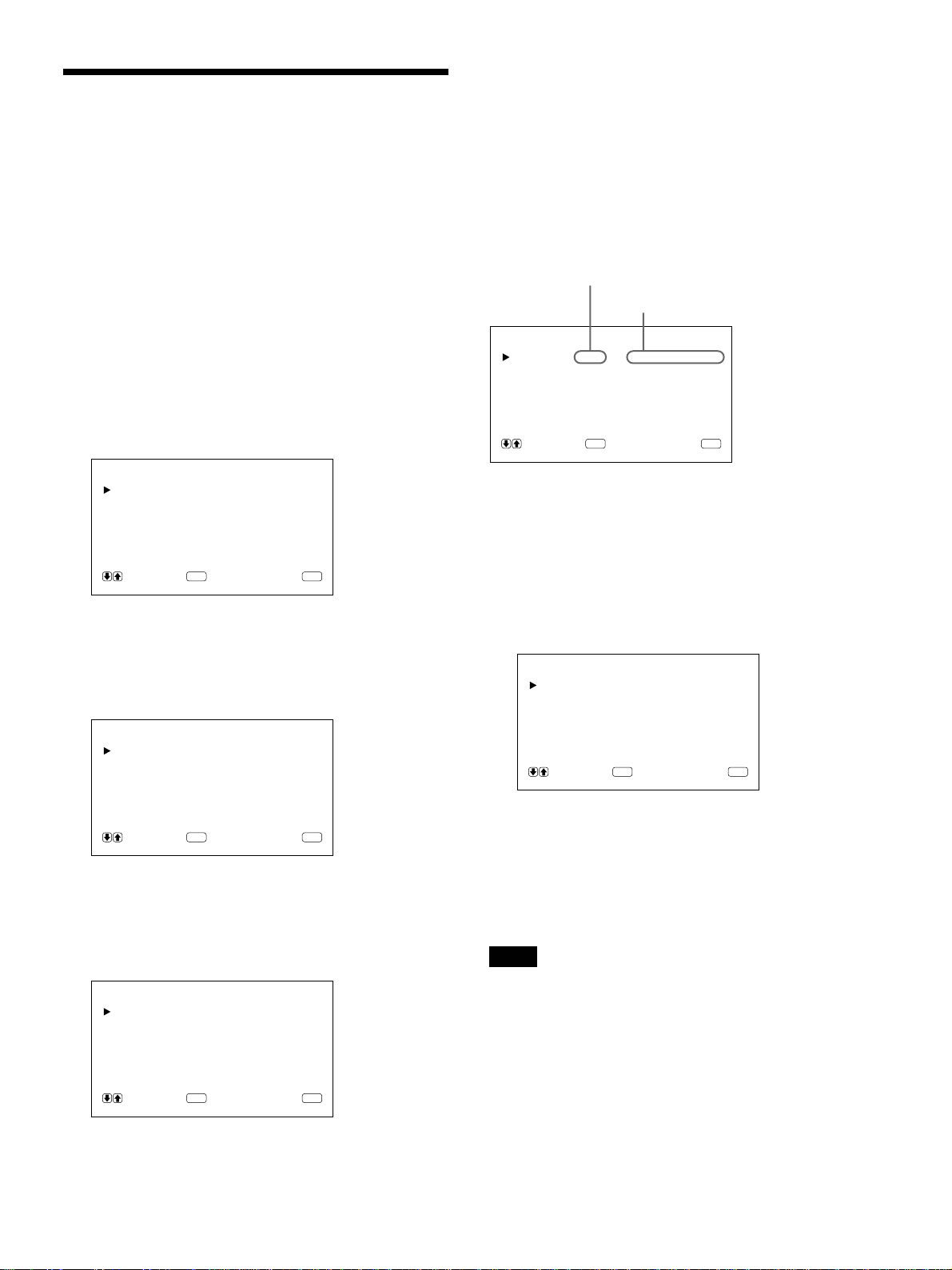
Using the Memory
“COMPLETED” message appears for about five
seconds.
The current data is stored under the selected
memory number.
If any data has been stored in the selected memory
number, the signal type and the color system or
horizontal frequency/vertical frequency are now
displayed on the right column next to the selected
memory number.
Signal type
Color system or horizontal/vertical frequency
SAVE
MEM 1:RGB 31.5
MEM 2 : EMPTY
MEM 3 : EMPTY
MEM 4 : EMPTY
MEM 5 : EMPTY
SELECT CANCEL
ENTER
kHz60Hz
MENU
Calling Up the Stored Condition
1 In the MEMORY menu, press M/m to move the
cursor (B) to “LOAD” and press ENT.
The following menu appears on the monitor
screen.
LOAD
MEM 1 : RGB 31 . 5
MEM 2 : EMPTY
MEM 3 : EMPTY
MEM 4 : EMPTY
MEM 5 : EMPTY
SELECT CANCEL
ENTER
kHz60Hz
MENU
SELECT CANCEL
ENTER
MENU
3 Press M/m to move the cursor (B) to “SAVE” and
press ENT.
The following menu appears on the monitor
screen.
SAVE
MEM 1 : EMPTY
MEM 2 : EMPTY
MEM 3 : EMPTY
MEM 4 : EMPTY
MEM 5 : EMPTY
SELECT CANCEL
ENTER
MENU
4 Press M/m to move the cursor (B) to MEM 1 to 5
and press ENT.
2 Press M/m to move the cursor (B) to MEM 1 to 5
and press ENT.
“COMPLETED” message appears for about five
seconds.
The picture is adjusted to the selected condition.
Notes
•You cannot recall the memory data if the selected
signal is different from the preset signal.
•The following items can be memorized:
PIC CONTROL menu
– CONTRAST
– BRIGHTNESS
– CHROMA
– PHASE
– COLOR TEMP
– PICTURE AGC
25 (GB)
Page 26

Using the Memory / Selecting the On-screen Language / Self-diagnosis Function
PIC SIZE menu
– H SIZE
– H SHIFT
– V SIZE
– V SHIFT
– ASPECT
CONFIG menu
– ENHANCE
– H FILTER
Selecting the On-screen Language
You can select the on-screen language among five
languages.
Available languages are: English, German, French,
Italian and Spanish.
1 Press MENU.
The main menu appears on the monitor screen.
3 Press M/m to move the cursor (B) to
“LANGUAGE” and press ENT.
The following menu appears on the monitor
screen.
LANGUAGE
ENGL I SH
DEUTSCH
FRANÇA I S
ITALIANO
ESPAÑOL
SELECT CANCEL
ENTER
MENU
4 Press M/m to move the cursor (B) to desired
language and press ENT.
The on-screen language is switched to the one you
selected.
ENGLISH: English
DEUTSCH: German
FRANÇAIS: French
ITALIANO: Italian
ESPAÑOL: Spanish
5 Press MENU.
The menu returns to the CONFIG menu.
MA IN MENU
PIC CONTROL
PIC SIZE
CONF I G
MEMORY
REMOTE
STATUS
SELECT CANCEL
ENTER
MENU
2 Press M/m to move the cursor (B) to “CONFIG”
and press ENT.
The CONFIG menu appears on the monitor
screen.
CONF I G
ENHANCE : H IGH
H F ILTER :AUTO
DISPLAY : ON
LANGUAGE
SELECT CANCEL
ENTER
MENU
Self-diagnosis Function
The unit has a self-diagnosis function.
This function displays the monitor’s condition with
the 1 indicator flashing and numbers on the
SERVICE CODE indicator. The numbers inform you
of the monitor’s current condition.
When the unit is working properly, only the dot at the
lower-right position on the SERVICE CODE indicator
flashes.
If the 1 indicator flashes, check the number and
contact your authorized Sony dealer.
1 Check the two-digit number on the SERVICE
CODE indicator.
The indicator shows one number, or multiple
numbers alternately every a half second.
2 Unplug the unit.
Inform the number to your authorized Sony
dealer.
26 (GB)
Page 27
Operating a Specific Monitor
ON
ID MODE
SET
OFF
Operating a Specific Monitor with the Remote Commander
4 After necessary adjustment, press ID MODE OFF.
The monitor returns to the normal mode.
with the Remote Commander
Using the supplied Remote Commander, you can
operate a specific monitor without affecting other
monitors that are installed together.
1 Press ID MODE ON on the Remote Commander.
Monitor index numbers appear in white characters
on all the monitors. (Every monitor is allocated an
individual preset index number from 1 to 255.)
See “To change the index number” in the column to the
right on this page to change the index number.
Index number
ON
SET
OFF
ID MODE
INDEX NO. 117 . . .
To change the index number
You can change the index number if necessary.
When you change the number, use the buttons on the
monitor.
1 Press MENU.
ON
SET
OFF
ID MODE
The main menu appears on the monitor screen.
MA IN MENU
PIC CONTROL
PIC SIZE
CONF I G
MEMORY
REMOTE
STATUS
SELECT CANCEL
ENTER
MENU
2 Input the index number of the monitor you want to
operate using 0 – 9 buttons on the Remote
Commander.
The input number appears right next to each
monitor’s own index number.
Input number
INDEX NO. 117 117
10/0
2
1
4
7
3
5
6
8
9
3 Press ID MODE SET.
The character on the selected monitor changes to
cyan while others change to red.
2 Press M/m to move the cursor (B) to “REMOTE”
and press ENT.
The REMOTE menu appears on the monitor
screen.
REMOTE
INDEX NO. : 001
REMOT E MOD E : TV
REMOTE ONLY : OFF
SELECT CANCEL
ENTER
MENU
3 Press M/m to move the cursor (B) to “INDEX
NO.” and press ENT.
The following menu appears on the monitor
screen.
INDEX NO. : 001
You can operate only a specified monitor. (All
operations are available in ID mode except
POWER ON/OFF.)
4 Select the index number with M/m and press ENT.
The menu returns to the REMOTE menu.
27 (GB)
Page 28
Using the Other Remote Commander
Using the Other Remote
Commander
The following operations can be controlled.
•Power on/off
•Input selection
•Menu operations
•Picture adjustments: contrast, phase and chroma
•On-screen display on/off (only for video monitors
and TVs)
The available operations and the buttons to be used
for each operation are limited depending on each
Remote Commander. See the table below.
Remote Commander model RM-854 RM-1271 RM-PJ1292 RM-PJ1000
REMOTE MODE setting TV PJ PJ PJ
Input selection RGB1 RGB A A A
RGB2 — B B B
LINE LINE1 VIDEO VIDEO VIDEO
Menu operation MENU MENU PAGE or < PAGE or < MENU or <
ENTER ENTER ,,ENTER or ,
++MMM
––mmm
Picture adjustment Contrast CONTRAST+/– CONTR+/– CONTR+/– CONTR+/–
Chroma CHROMA+/– COLOR+/– COLOR+/– COLOR+/–
Phase PHASE+/– HUE+/– HUE+/– HUE+/–
On-screen information DISPLAY — STATUS ON STATUS ON
28 (GB)
Page 29

Specifications
Video processing
Capture range Horizontal rate: 15.6 to 80 kHz
Vertical rate: 48 to 120 Hz
Preset signal Input: 12 formats (See page
21 (GB))
Video memory 1,152 × 1,152 × 24 bits (RGB
total)
Sampling rate 14.3 to 50 MHz offset phase max.
(equivalent to 100 MHz
sampling)
Panel system AC-type Plasma Display Panel
Display resolution 1024 dots × 1024 lines
Pixel pitch
Picture size
Panel size 42-inch (diagonal 1,058 mm)
0.90 (horizontal) × 0.51 (vertical)
(1⁄16 × 1⁄32 inches)
mm
921 (horizontal) × 522 (vertical)
(36 3⁄8 × 20 5⁄8 inches)
mm
Specifications
LINE (NTSC, PAL)
VIDEO IN BNC-type (×1)
Composite video, 1 Vp-p ±2 dB
sync negative, 75-ohm
(automatic termination)
Y/C IN Mini DIN 4-pin type (×1)
Y (luminance): 1 Vp-p ±2 dB sync
negative, 75-ohm (automatic
termination)
C (chrominance): Burst
0.286 Vp-p ±2 dB (NTSC),
75-ohm (automatic termination)
Burst 0.3 Vp-p ±2 dB (PAL)
75-ohm (automatic termination)
AUDIO IN (L, R) Phono jack (×2)
500 mVrms, high impedance
VIDEO OUT BNC-type (×1) Loop-through
Y/C OUT Mini DIN 4-pin type (×1) Loop-
through
AUDIO OUT (L, R) (Variable output)
Phono jack (×2) Loop-through
Inputs and Outputs
RGB1
R (R-Y)/ G (Y)/B (B-Y) IN
BNC-type (×3)
0.714 Vp-p/non-composite 75-ohm
(automatic termination)
1 Vp-p/composite 75-ohm
(automatic termination)
SYNC IN(HD/COMP, VD)
BNC-type (×2)
H (or composite) SYNC, V SYNC,
1 to 5 Vp-p high impedance
AUDIO IN (L, R) Phono jack (×2)
500 mVrms, high impedance
R (R-Y)/ G (Y)/B (B-Y) OUT
BNC-type (×3) Loop-through
SYNC OUT (HD/COMP, VD)
BNC-type (×2) Loop-through
H (or composite) SYNC,
V SYNC
AUDIO OUT (L, R)
Phono jack (×2) Loop-through
RGB2
RGB IN D-sub 15-pin
See “Pin assignment” on page
30 (GB).
AUDIO IN (L, R) Phono jack (×2)
500 mVrms, high impedance
MONITOR OUT AUDIO (L, R)
Phono jack (×2)
Maximum 500 mVrms, high
impedance
CONTROL S (IN, OUT)
Mini jack (stereo) (×2)
5 Vp-p
REMOTE (RS-232C)
Mini DIN 8-pin (×1)
SPEAKERS 6 to 16 ohms, 7 W + 7 W (when
the impedance is 8 ohms)
General
Power requirements
100 to 120 V AC, 50/60 Hz,
4.7 A/410 W
220 to 240 V AC, 50/60 Hz,
2.2 A/400 W
Operating conditions
Temperature: 0°C to 35°C (32°F to
95°F)
Humidity: 20% to 90% (no
condensation)
Atmospheric pressure: 700 to
1060 hPa
29 (GB)
Page 30
Specifications
Storing/transporting conditions
Temperature: –10°C to +40°C
(14°F to 104°F)
Humidity: 20% to 90% (no
condensation)
Atmospheric pressure: 700 to
1060 hPa
Dimensions 1036 × 636 × 152 mm
(40 7⁄8 × 25 1⁄8 × 6 1⁄8 inches) (w/h/d)
Mass 45 kg (99 lb 3 oz)
Supplied accessories
AC power cord (1)
AC plug holder (1)
Remote Commander RM-921 (1)
Size AA (R6) batteries (2)
Ferrite core (2)
Foot support bracket (2)
Screws for foot support bracket (6)
Monitor stabilizer (2)
Operating instructions (1)
Design and specifications are subject to change
without notice.
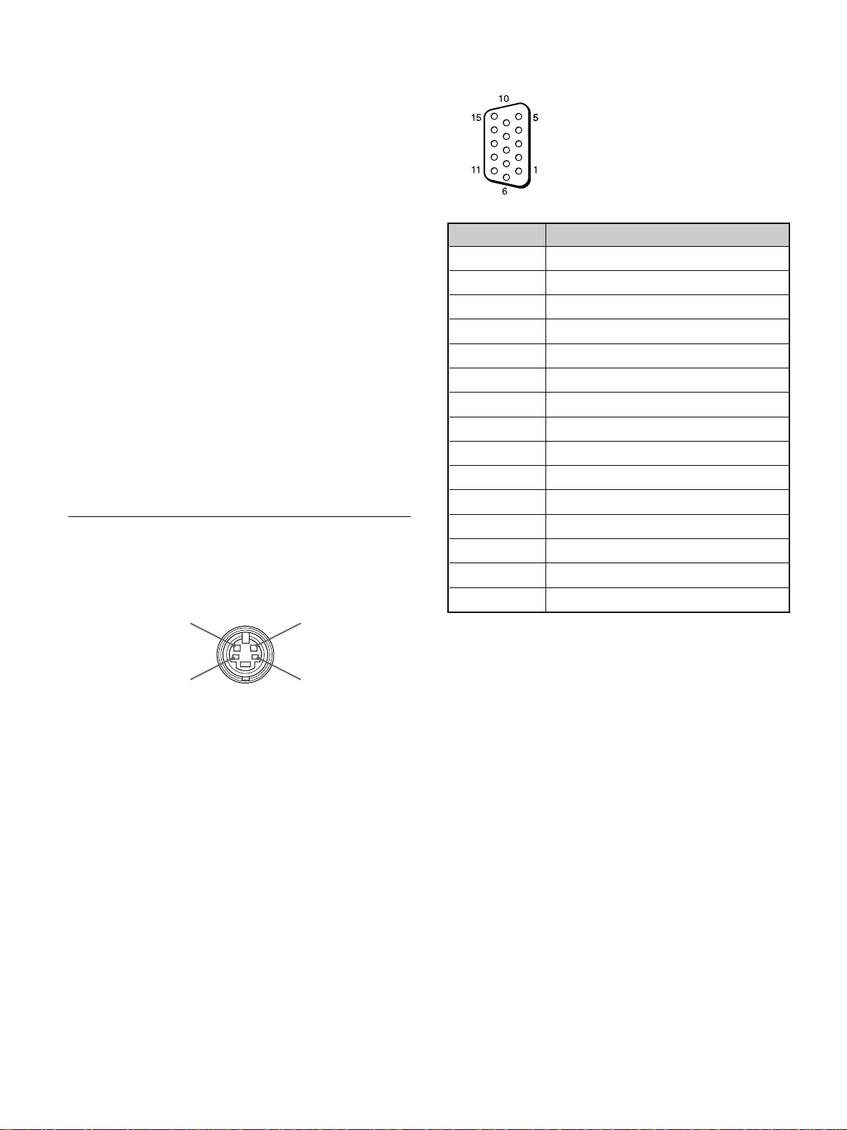
RGB IN connector (D-sub 15-pin)
Pin No. Signal
1 Red video or R-Y
2 Green video or Y
3 Blue video or B-Y
4 Ground
5 Ground
6 Red ground
7 Green ground
8 Blue ground
9 Not used
10 Ground
Pin assignment
Y/C jack (Mini DIN 4-pin)
Chrominance
GND
11 Ground
12 SDA
13 H sync or composite sync
14 V sync
15 SCL
Luminance
GND
30 (GB)
Page 31

31 (GB)
Page 32

AVERTISSEMENT
Pour prévenir tout risque d’incendie ou
d’électrcution, garder cet appareil à l’abri de la
pluie et de l’humidité.
De dangereuses hautes tensions circulent à
l’intérieur de cet appareil. N’ouvrez pas le
châssis.
Confiez-en l’entretien exclusivement à un
personnel qualifié.
Pour les utilisateurs au Canada
Cet appareil est numérique de la classe A est conforme à la
norme NMB-003 du Canada.
Pour les utilisateurs en Europe
Il s’agit d’un produit de Classe A. Dans un environnement
domestique, cet appareil peut provoquer des interférences
radio, dans ce cas l’utilisateur peut être amené à prendre
des mesures appropriées.
Aux utilisateurs de PFM-510A1WE
CET APPAREIL DOIT ETRE RACCORDE ALA
TERRE
Remarque
Si vous raccordez un ordinateur à ce moniteur,
attachez les tores de ferrite fournies. Si vous ne le
faites pas, ce moniteur ne satisfera pas aux normes
FCC/IC/CE (EN55022) obligatoires.
Fixation des tores de ferrite
Ajustez les tores de ferrite aux deux extrémités du
cordon d’alimentation secteur. Refermez
correctement le couvercle jusqu’à ce que les agrafes
s’encliquettent.
ou
Agrafes
IMPORTANT
Les couleurs des conducteurs de cordon d’alimentation
secteur correspondent au code suivant:
Vert-et-jaune : Terre
Bleu
: Neutre
Brun : Phase d’alimentation
Comme ces couleurs peuvent différer des repères colorés
figurant sur votre prise, proceder comme suit:
Le fil vert-et-jaune doit être connecté à la borne repérée par
la lettre E, par le symbole I de terre, ou par la couleur verte
ou verte-et-jaune.
Le fil bleu doit être connecté à la borne repérée par la lettre
N ou par la couleur noire.
Le fil brun doit être connecté à la borne repérée par la lettre
L ou par la couleur rouge.
La prise doit être près de l’appareil et facile d’accès.
2 (FR)
Page 33

Table des matières
Précautions ................................................................4 (FR)
Caractéristiques ........................................................ 5 (FR)
Emplacement et fonction des pièces et
commandes ...........................................................6 (FR)
Avant / Côtés ............................................................ 6 (FR)
Panneau de commande.............................................. 7 (FR)
Panneau du connecteur droit..................................... 8 (FR)
Panneau du connecteur gauche ............................... 10 (FR)
Télécommande RM-921 ......................................... 10 (FR)
Installation................................................................ 12 (FR)
Utilisation des pieds rétractables ............................ 12 (FR)
Attention ................................................................. 13 (FR)
Raccordements........................................................ 14 (FR)
Raccordement de la prise d’alimentation secteur ... 14 (FR)
Exemple de raccordement....................................... 14 (FR)
Utilisation des menus d’affichage ......................... 16 (FR)
Exploitation des menus ...........................................16 (FR)
Guide de menu ........................................................ 16 (FR)
Visualisation de l’image..........................................20 (FR)
Commutation de l’image ........................................ 20 (FR)
Affichage du signal d’entrée et des données d’état du
moniteur .............................................................20 (FR)
Réglage de l’image .................................................. 22 (FR)
Réglage du contraste, de la luminosité, de l’intensité des
couleurs et de la phase ....................................... 22 (FR)
Restauration des réglages par défaut des options du menu
CTRL IMAGE ................................................... 22 (FR)
Redimensionnement et positionnement de
l’image..................................................................23 (FR)
Réglage de la taille de l’image................................ 23 (FR)
Réglage de la position de l’image........................... 23 (FR)
Restauration de la taille et de la position originales de
l’image ............................................................... 24 (FR)
Utilisation de la mémoire ........................................ 25 (FR)
Mémorisation des réglages sélectionnés................. 25 (FR)
Restauration des réglages sauvegardés ................... 25 (FR)
Sélection de la langue d’affichage à l’écran ......... 26 (FR)
Fonction d’auto-diagnostic .................................... 26 (FR)
Utilisation d’un moniteur spécifique avec la
télécommande..................................................... 27 (FR)
Utilisation de l’autre télécommande ...................... 28 (FR)
Spécifications .......................................................... 29 (FR)
FR
Français
3 (FR)
Page 34

Précautions
Précautions
Sécurité
•Faites fonctionner l’appareil sur une tension de 100 à
120 V CA ou 220 à 240 V CA.
•La plaquette signalétique indiquant la tension de
fonctionnement, la consommation électrique, etc. est
située à l’arrière de l’appareil.
•Si des objets solides ou des liquides pénètrent à
l’intérieur du châssis, débranchez le moniteur et
faites-le vérifier par un personnel qualifié avant de le
remettre en service.
•Débranchez le cordon de la prise si vous prévoyez de
ne plus utiliser le moniteur pendant quelques jours
ou plus.
•Pour débrancher le cordon, tirez-le par la fiche. Ne
tirez jamais sur le cordon proprement dit.
•Si l’appareil est installé sur le sol, utilisez les pieds
rétractables.
Nettoyage
Pour garder à l’appareil l’aspect du neuf, nettoyez-le
régulièrement à l’aide d’une solution détergente
douce. N’utilisez jamais de solvants tels que de
l’alcool ou de l’essence ni de nettoyants abrasifs sous
peine de ternir le fini de l’appareil. Par mesure de
sécurité, débranchez l’appareil avant de le nettoyer.
Remballage
Conservez le carton d’emballage et les matériaux de
conditionnement car ils constituent une protection
idéale en vue du transport de l’appareil. Lors du
transport de l’appareil, remballez-le comme illustré
sur le carton.
Pour toute question au sujet de cet appareil, consultez
un distributeur Sony agréé.
Installation
•Veillez à assurer une circulation d’air adéquate pour
éviter une surchauffe interne de l’appareil. Ne placez
pas l’appareil sur des surfaces textiles (tapis,
couvertures, etc.) ni à proximité de rideaux ou de
draperies susceptibles d’obstruer les orifices de
ventilation.
•N’installez pas l’appareil à proximité de sources de
chaleur comme un radiateur ou une bouche d’air
chaud, ni dans un endroit exposé au rayonnement
solaire direct, à des poussières en excès, à des
vibrations ou à des chocs mécaniques.
•Lorsque vous installez plusieurs équipements avec
cet appareil Les phénomènes suivants peuvent se
produire en fonction de la position de l’appareil et
des autres équipements: dysfonctionnement de la
télécommande, image parasitée, son parasité.
PDP (Ecran d’affichage à plasma)
•Il se peut qu’il y ait de minuscules points noirs et/ou
clairs sur le PDP. Ces points sont normaux.
•N’affichez pas une même image fixe à l’écran
pendant une période prolongée. Sinon, une image
rémanente peut apparaître sur une partie d’un
panneau. Utilisez éventuellement un économiseur
d’écran pour égaliser l’affichage sur écran.
4 (FR)
Page 35

Caractéristiques
Les séries de PFM-510A1W sont des moniteurs 16:9e
à panneau plat de 42 pouces adoptant le PDP (écran
d’affichage à plasma) et acceptant différents types de
signaux grâce au convertisseur à balayage intégré.
Qualité d’image améliorée
Le PDP produit une image de plus haute qualité avec
1024 × 1024 lignes, ce qui permet des images HDTV
et PC finement détaillées.
Vous pouvez obtenir une luminosité et un contraste
supérieurs par rapport aux moniteurs classiques.
Convertisseur de balayage interne à hautes
performances
Le moniteur intègre un convertisseur à balayage à
hautes performances. Au moyen d’un algorithme
unique, le moniteur traite les signaux dans une large
gamme de formats – vidéo, HDTV, PC, etc.
Flexibilité
Un connecteur d’option est prévu pour une extension
future.
L’adaptateur d’option enfichable permet une mise à
jour système simple et rapide.
Caractéristiques
Autres caractéristiques
•Trois jeux d’entrée vidéo avec des entrées audio: une
entrée vidéo composite ou Y/C, une entrée RVB et
une entrée RVB/composante.
•Affiche le signal HDTV avec le signal de synchro à
trois niveaux.
•Filtre en peigne tridimensionnel pour la séparation
NTSC Y/C.
•Filtre en peigne à corrélation de ligne pour la
séparation Y/C PAL.
•Détection automatique du signal d’entrée avec
indication.
1)
•Compatible avec Windows95/98
PnP (Plug and
Play).
•Fonction Picture AGC — cette fonction règle
automatiquement et améliore le contraste lorsqu’un
signal de faible intensité est entré.
•Menus d’affichage sur écran pour différents réglages
et sélections
•Affichage sur écran en cinq langues pour un accès
plus convivial.
•Réglage fin de la taille et de la position de l’image
•Fonction de mémoire pour l’enregistrement de cinq
réglages d’image.
•Commande ID
•Fonction d’auto-diagnostic.
•Connecteur REMOTE (RS-232C) (mini connecteur
DIN à 8 broches)
•Connecteur CONTROL S
•Accepte les signaux des télécommandes infrarouges
ou filaires Sony utilisant le code SIRCS.
•Réglage vertical
Avertissement sur la connexion électrique
Utilisez un cordon d’alimentation approprié à votre tension secteur locale.
Etats-Unis, Europe Royaume-Uni, Irlande, Japon
Canada continentale Australie, Nouvelle-Zélande
Type de fiche VM0033B COX-07 636 — VM1296
Extrémité femelle VM0113 COX-02 VM0310B VM0303B VM1313
Type de cordon SJT H05VV-F CEE (13) 53rd (O.C) HVCTF
Capacité nominale 13A/125V 10A/250V 10A/250V 10A/125V
minimum du cordon
Agréation de sécurité UL/CSA VDE VDE DENTORI
.........................................................................................................................................................................................................
1) Windows95/98 est une marque déposée de Microsoft Corporation.
5 (FR)
Page 36

Emplacement et fonction des pièces et commandes
Emplacement et fonction
des pièces et commandes
Avant / Côtés
Avant
5 Panneau du connecteur droit
Pour plus de détails sur le panneau du connecteur droit,
voir “Panneau du connecteur droit” à la page 8 (FR).
6 Couvercle du panneau droit
Ouvrez-le lorsque vous utilisez le panneau du
connecteur droit.
Pour plus de détails sur l’ouverture du couvercle du
panneau, voir ci-dessous.
Pour ouvrir le couvercle du panneau
Desserrez les vis en tournant dans le sens antihoraire
et ouvrez le couvercle.
Côté gauche
3
1
Côté droit
4
2
6
5
1 Pieds rétractables
Servent à régler le moniteur au sol.
Pour plus de détails sur l’utilisation des pieds rétractables,
voir “Utilisation des pieds rétractables” à la page 12 (FR).
2 Panneau de commande
Pour plus de détails sur le panneau de commande, voir
“Panneau de commande” à la page 7 (FR).
Pour ôter le couvercle du panneau
Desserrez les vis comme illustré ci-dessous et retirez
le couvercle du panneau.
Vis
Pour installer la télécommande dans le
couvercle du panneau
Mettez la télécommande en place à l’arrière du couvercle
de panneau gauche comme illustré ci-dessous.
3 Couvercle du panneau gauche
Ouvrez-le lorsque vous utilisez le panneau du
connecteur gauche.
Vous pouvez installer la télécommande à l’arrière de
ce couvercle.
Pour plus de détails sur l’ouverture du couvercle du
panneau, voir ci-contre à droite.
4 Panneau du connecteur gauche
Pour plus de détails sur le panneau du connecteur gauche,
voir “Panneau du connecteur gauche” à la page 10 (FR).
6 (FR)
Télécommande
Remarque
Lors du rangement de la télécommande, veillez à ce
que le dessus de la télécommande soit tourné vers le
haut et que l’arrière soit orienté vers l’extérieur.
Page 37

Panneau de commande
Emplacement et fonction des pièces et commandes
VOL – VOL + MENU ENT RGB1 YUV RGB2 LINE Y/C CTRL
qd qs qa 0 98765 4 32 1
mM
1 Capteur de télécommande
Capte le faisceau de la télécommande.
2 Commutateur 1 (veille)/indicateur 1 (veille)
Appuyez pour mettre le moniteur sous tension.
Appuyez de nouveau pour revenir en mode de veille.
L’indicateur 1 (veille) s’allume en rouge en mode de
veille.
Lorsque l’indicateur 1 clignote, voir “Fonction d’autodiagnostic” à la page 26 (FR).
3 Indicateur d’alimentation
S’allume lorsque le moniteur est mis sous tension.
4 Touche CTRL (commande)
our exploiter les touches du panneau de commande,
appuyez tout d’abord sur cette touche. Ensuite, les
touches s’allument ou clignotent pour indiquer
qu’elles peuvent être utilisées. Appuyez de nouveau
sur la touche pour les désactiver.
1
9 Touche RGB1
Sélectionnez l’entrée du signal RVB à partir des
connecteurs RGB1.
0 Touche ENT (entrée)
Appuyez pour sélectionner l’option désirée dans un
menu.
qa Touche M/m
Appuyez pour déplacer le curseur (B) sur une option
ou pour régler une valeur d’un menu.
qs Touche MENU
Appuyez pour faire apparaître le menu.
qd Touches VOL (volume) +/–
Appuyez sur la touche + pour augmenter le volume ou
sur la touche – pour diminuer le volume.
Remarque
Les touches (sauf pour le commutateur 2 1 (veille))
du panneau de commande ne fonctionnent pas si vous
n’appuyez pas d’abord sur la touche CTRL.
5 Touche Y/C
Sélectionnez l’entrée du signal à partir de la prise Y/C
IN dans les connecteurs LINE.
6 Touche LINE
Sélectionnez l’entrée de signal à partir du connecteur
VIDEO IN dans les connecteurs LINE.
7 Touche RGB2
Sélectionnez l’entrée du signal à partir des
connecteurs RGB2.
8 Touche YUV
Sélectionnez l’entrée du signal composante à partir
des connecteurs RGB1.
7 (FR)
Page 38

Emplacement et fonction des pièces et commandes
Panneau du connecteur droit
RGB 1
IN OUT
R
R-Y
G
Y
B
B-Y
1
2
3
HD/
COMP
VD
L
R
RGB 2
RGB IN
L
R
VIDEO
Y/C
L
R
IN OUT
LINE
REMOTE
(RS-232C)
4
SYNC
AUDIO
AUDIO IN
5
AUDIO
6
HD/COMP IN (type BNC): Entrez le signal de
synchro H ou composite. Effectuez le
raccordement à la sortie d’un signal de synchro H
ou composite d’un ordinateur ou d’un équipement
vidéo.
VD IN (type BNC): Entrez le signal de synchro V.
Effectuez le raccordement à la sortie du signal de
syncho V d’un ordinateur ou d’un équipement
vidéo.
Le signal de synchro externe est sélectionné
automatiquement. Voir le tableau des priorités cidessous.
Connector Signaux de synchro entré d’entrée
HD/COMP IN H Sync Comp Sync —
VD IN V Sync — —
G(Y) IN Sync on G Sync on G Sync on G
Signaux de H Sync Comp Sync Sync on G
synchro à V Sync
sélectionner
AUDIO IN (L/R) (type phono): Entrez le signal
audio. Effectuez le raccordement à la sortie audio
d’un ordinateur ou équipement vidéo. Effectuez
le raccordement au canal L lorsque le signal
audio est en mono.
2 Connecteurs RGB2 IN
RGB IN (D-sub à 15 broches): Effectuez le
raccordement à la sortie du signal RVB d’un
ordinateur.
AUDIO IN (L/R) (type phono): Entrez le signal
audio. Effectuez le raccordement à la sortie audio
d’un ordinateur. Effectuez le raccordement au
canal L lorsque le signal audio est en mono.
Remarque
Le procédé d’optimisation d’image pour les signaux
vidéo (NTSC, PAL) est uniquement opérant pour les
entrées composite (Y/C) ou composante (Y/R-Y/BY).
L’image de l’entrée RVB peut être floue. C’est
normal.
1 Connecteurs RGB1 IN
R (R-Y)/G (Y)/B (B-Y) IN (type BNC): Entrez le
signal RVB analogique ou le signal composante.
Effectuez le raccordement à la sortie du signal
RVB ou composante (Y/B-Y/R-Y) d’un
ordinateur ou d’un équipement vidéo.
Cet appareil accepte également le signal
composante HD (Y/P
connecteur B (B-Y) IN et le signal P
B/PR). Entrez le signal PB au
R au
connecteur R (R-Y) IN.
8 (FR)
3 Connecteurs LINE IN
VIDEO IN (type BNC): Effectuez le raccordement
à la sortie du signal vidéo composite d’un
équipement vidéo.
Y/C IN (mini DIN à 4 broches): Effectuez le
raccordement à la sortie du signal Y/C d’un
équipement vidéo.
AUDIO IN (L/R) (type phono): Effectuez le
raccordement à la sortie audio d’un équipement
vidéo. Effectuez le raccordement au canal L
lorsque le signal audio est en mono.
Page 39

Emplacement et fonction des pièces et commandes
4 Connecteurs RGB1 OUT
Ces connecteurs servent de sortie en boucle directe
pour les connecteurs RGB1 IN 1.
Lorsque la prise est raccordée aux connecteurs RGB
OUT, la terminaison à 75 ohms des connecteurs RGB
IN est libérée et l’entrée de signal vers les connecteurs
RGB IN est émise à partir de ces connecteurs.
R (R-Y)/G (Y)/B (B-Y) OUT (type BNC): Sorties
en boucle directe des connecteurs RGB IN.
Effectuez le raccordement à l’entrée de signal
RVB ou composante (Y/B-Y/R-Y) d’un autre
moniteur.
HD/COMP OUT (type BNC): Sortie en boucle
directe du connecteur HD/COMP IN. Effectuez le
raccordement à l’entrée du signal de synchro H
ou composite d’un autre moniteur.
VD OUT (type BNC): Sortie en boucle directe du
connecteur VD IN. Effectuez le raccordement à
l’entrée du signal de synchro V d’un autre
moniteur.
Remarque
Les connecteurs HD/COMP OUT et VD OUT sont
des sorties à haute impédance.
Lorsque vous utilisez ces sorties, il est conseillé de
raccorder un moniteur doté d’un connecteur d’entrée
de synchro à haute impédance, sinon l’image risque
de disparaître en raison de la différence de niveau du
signal de synchro.
6 Connecteur REMOTE (RS-232C) (mini
connecteur DIN à 8 broches)
Ce connecteur vous permet de commander le
moniteur à distance à l’aide du protocole RS-232C.
Pour plus de détails, consultez votre revendeur Sony
agréé.
AUDIO OUT (L/R) (type phono): Sorties en
boucle directe des prises AUDIO IN. Effectuez le
raccordement aux entrées audio d’un autre
moniteur.
5 Connecteurs LINE OUT
Ces connecteurs servent de sorties en boucle directe
pour les connecteurs 3 LINE IN.
Lorsque la prise est raccordée aux connecteurs
VIDEO OUT ou à la prise Y/C OUT, la terminaison à
75 ohms du connecteur VIDEO IN ou de la prise Y/C
IN est libérée et le signal entré vers la prise VIDEO
IN ou Y/C IN est émis à partir du connecteur VIDEO
OUT ou de la prise Y/C OUT.
VIDEO OUT (type BNC): Effectuez le
raccordement à l’entrée du signal vidéo
composite d’un autre moniteur ou d’un
équipement vidéo.
Y/C OUT (mini DIN à 4 broches): Effectuez le
raccordement à l’entrée du signal Y/C d’un autre
moniteur ou d’un équipement vidéo.
AUDIO OUT (L/R) (type phono): Sorties en
boucle directe des prises AUDIO IN. Effectuez le
raccordement aux entrée audio d’un autre
moniteur ou équipement vidéo.
9 (FR)
Page 40

Emplacement et fonction des pièces et commandes
Panneau du connecteur gauche
MONITOR OUT
AUDIO
RL
VARIABLE
CONTROL S
IN
+
R–
SPEAKERS
(6-16 Ω)
SERVICE CODE
OUT
8.8.
1
2
+
L
3
–
4
Remarques
•Si vous raccordez la prise CONTROL S IN à la prise
CONTROL S OUT de l’autre équipement, vous ne
pourrez pas utiliser le moniteur avec la
télécommande.
•Vous pouvez utiliser le câble stéréo à minifiche au
lieu du câble CONTROL S.
3 Bornes SPEAKERS L/R
Raccordez des haut-parleurs de 6 à 16 ohms
d’impédance.
Remarque
Ne raccordez pas en même temps le cordon du hautparleur au moniteur et à un amplificateur, sinon un
courant électrique excessif risque de passer de
l’amplificateur et d’endommager le moniteur.
4 Indicateur SERVICE CODE
Cet indicateur est destiné exclusivement au personnel
qualifié.
5
AC IN
1
Prises MONITOR OUT AUDIO (L/R) (type phono)
Sortez le signal entré par les prises AUDIO IN.
Effectuez le raccordement aux entrées audio d’un
amplificateur audio (non fourni).
Remarque
Ces prises sont des sorties variables. Mettez le volume au
maximum pour régler le niveau de sortie sur 500 mVrms.
2 Prises CONTROL S IN/OUT (miniprises)
Effectuez le raccordement aux prises CONTROL S de
l’équipement vidéo ou d’autres moniteurs. Ce
raccordement vous permettra de commander
simultanément tous les équipements au départ d’une
seule télécommande.
Pour commander l’équipement en orientant la
télécommande fournie vers le capteur de
télécommande du moniteur, effectuez le raccordement
à la prise CONTROL S OUT du moniteur et à la prise
CONTROL S IN de l’autre équipement.
5 Prise - AC IN
Raccordez le cordon d’alimentation secteur fourni à
cette prise et au mur. Dès que vous branchez le cordon
d’alimentation secteur, le moniteur passe en mode de
veille.
Télécommande RM-921
1
2
3
4
5
6
7
8
9
0
qa
MUTING
RGB1
LINE
1
4
7
10/0
STILL
POWER
ON
OFF
ON
SET
OFF
ID MODE
DISPLAY
RGB2
Y/C
2
5
8
ZOOM
SELECT
VOL
POWER
YUV
MTS/MPX
3
6
9
CH
DEGAUSS
MENU
ENTER
CH
qs
qd
qf
qg
qh
qj
qk
ql»
w;…
wa
10 (FR)
Page 41

Emplacement et fonction des pièces et commandes
1 Commutateur POWER
Appuyez pour mettre le moniteur sous tension.
Appuyez de nouveau pour revenir en mode de veille.
Remarque
Lors de l’utilisation de moniteurs multiples, appuyez
sur ce commutateur pour mettre les moniteurs qui sont
déjà sous tension en mode de veille ou mettre sous
tension les moniteurs en mode de veille.
2 Touche MUTING
Appuyez pour couper le son. Appuyez de nouveau sur
cette touche ou appuyez sur la touche VOL (volume)
+/– pour rétablir le son.
3 Touches RGB1/RGB2
Sélectionnez le signal entré par les connecteurs RGB1
ou RGB2.
4 Touche LINE
Sélectionne l’entrée de signal à partir du connecteur
VIDEO IN dans les connecteurs LINE.
5 Touche Y/C
Sélectionne le signal entré par la prise Y/C IN des
connecteurs LINE.
6 Touches numériques
Appuyez pour sélectionner le numéro d’index.
7 Touche ZOOM
Cette touche ne fonctionne pas avec le moniteur.
et appuyez sur la touche SET. Une fois l’opération
terminée, appuyez sur la touche OFF pour revenir au
mode normal.
qs Touche DISPLAY
Affiche les informations de signal d’entrée en haut de
l’écran du moniteur. Appuyez de nouveau pour les
faire disparaître.
qd Touche YUV
Sélectionne le signal composante entré par les
connecteurs RGB1.
qf Touche MTS/MPX
Cette touche ne fonctionne pas avec le moniteur.
qg Touche CH
Cette touche ne fonctionne pas avec le moniteur.
qh Touche DEGAUSS
Cette touche ne fonctionne pas avec le moniteur.
qj Touches SELECT +M/–m
Appuyez pour déplacer le curseur (B) sur une option
ou pour régler une valeur du menu.
qk Touche MENU
Appuyez pour faire apparaître le menu.
ql Touche ENTER
Appuyez pour sélectionner l’option désirée dans un
menu.
8 Touche STILL
Cette touche ne fonctionne pas avec le moniteur.
9 Commutateur POWER ON
Appuyez pour mettre le moniteur sous tension.
Lorsque vous utilisez plusieurs moniteurs, vous
pouvez utiliser ce commutateur au lieu du
commutateur 1 POWER pour ne pas affecter un
autre moniteur déjà sous tension.
0 Commutateur POWER OFF
Appuyez pour mettre le moniteur en mode de veille.
Lorsque vous utilisez plusieurs moniteurs, vous
pouvez utiliser ce commutateur au lieu du
commutateur 1 POWER pour ne pas affecter
d’autres moniteurs déjà sous tension.
qa Touches ID MODE (ON/SET/OFF)
Appuyez sur la touche ON pour faire apparaître un
numéro d’index à l’écran. Ensuite, appuyez sur le
numéro d’index du moniteur que vous désirez utiliser
w; Touches VOL +/–
Appuyez sur la touche + pour augmenter le volume ou
la touche – pour diminuer le volume.
wa Touches CH +/–
Ces touches ne fonctionnent pas avec le moniteur.
11 (FR)
Page 42

Emplacement et fonction des pièces et commandes / Installation
Installation des piles
Introduisez deux piles AA (R6) en respectant la
polarité.
D’abord
l’extrémité
négative #.
E
e
e
E
•En mode d’utilisation normale, les piles devraient
durer environ six mois. Si la télécommande ne
fonctionne pas correctement, il est possible que les
piles soient épuisées. Les remplacer par des neuves.
•Pour éviter des dommages à la suite d’une fuite des
piles, retirez-les de la télécommande si vous
prévoyez de ne pas l’utiliser pendant une période
prolongée.
Lorsque la télécommande ne fonctionne pas
Vérifier que l’indicateur 1 s’allume. La
télécommande exploite le moniteur uniquement
lorsque celui-ci est sous tension ou en mode de veille.
Installation
Utilisation des pieds rétractables
Cette section décrit les disposition d’installation pour
l’installation du projecteur.
1 Tirez les boutons et tirez vers le bas sur les pieds
rétractables.
2 Sortez les pieds rétractables.
3 Enfoncez les pieds rétractables et verrouillez-les.
Remarque
Si vous branchez le câble à la prise CONTROL S IN
sur le côté du moniteur, vous ne pouvez pas utiliser le
moniteur avec la télécommande.
Pour fixer les pieds rétractables
Si l’appareil est installé sur le sol, fixez les pieds
rétractables.
Mettez en place les supports de fixation de pied
comme illustré ci-dessous.
12 (FR)
Page 43

Installation
Attention
•Lorsque vous installez le moniteur, assurez-vous
qu’il y a plus de place qu’illustré ci-dessous.
•La température ambiante doit être comprise entre
0°C – +35°C (32°F – 95°F).
Lors de l’utilisation des pieds rétractables
Avant
Mur
20 (7 7/8)
Côté
10
Mur Mur
(4)
Sol
5,5 (2 1/4)
10
(4)
2,5 (1)
Côté
3,5 (1 7/8)
Mur
Unité: cm (pouces)
Accroché au mur: verticalement
Avant
Mur
10 (4)
25
(9 7/8)
Assurez-vous que
la section de
commande se
trouve en bas.
20
(7 7/8)
10 (4)
Mur
MurMur
Mur
Sol
Unité: cm (pouces)
Lors de l’utilisation du support de
montage
Avant
10
Mur Mur
(4)
Mur
Mur
25 (9 7/8)
7
25 (9
10
(4)
/8)
Côté
5 (2)
Mur
Unité: cm (pouces)
13 (FR)
Page 44

Raccordements
Raccordements
Raccordement de la prise
d’alimentation secteur
1 Branchez la prise d’alimentation secteur dans une
prise AC IN. Ensuite, fixez le support de prise AC
(fourni) au cordon d’alimentation secteur.
Cordon
d’alimentation
Prise
AC IN
secteur
Support de prise
d’alimentation
2 Faites glisser le support de prise d’alimentation
secteur par-dessus le cordon jusqu’à ce qu’il
s’enclenche dans le logement de la prise
d’alimentation secteur.
Logement de
la prise AC IN
Pour ôter le cordon d’alimentation secteur
Pressez les côtés supérieur et inférieur et sortez le
support de prise secteur.
Exemple de raccordement
Avant de commencer
•Assurez-vous d’abord que tous les appareils sont
hors tension.
•Utilisez des câbles de connexion adaptés aux
appareils à raccorder.
•Les connecteurs de câbles doivent être complètement
insérés dans les prises. Une connexion lâche risque
de provoquer du souffle ou d’autres parasites.
•Pour débrancher un câble, saisissez-le par la fiche.
Ne tirez jamais sur le câble proprement dit.
•Lisez le mode d’emploi de l’appareil à raccorder.
14 (FR)
Page 45

Raccordements
vers la
sortie
audio
Ordinateur
vers la
sortie
vidéo
vers la
sortie
audio
vers la
sortie
vidéo
* vers R(R-Y)/G(Y)/B(B-Y),
HD/COMP, VD IN
vers AUDIO IN
vers RGB IN
vers Y/C ou
VIDEO IN
RGB 1
IN OUT
R-Y
B-Y
HD/
COMP
VD
RGB 2
RGB IN
VIDEO
Y/C
Magnétoscope
Betacam SP
vers la sortie du
signal
composante
R
G
Y
B
vers la
sortie
audio
* vers R(R-Y)/G(Y)/
SYNC
B(B-Y) IN
vers AUDIO IN
L
AUDIO
R
L
AUDIO IN
R
vers AUDIO IN
vers la sortie
vidéo
vers la sortie
audio
Magnétoscope, lecteur de disques
laser, console de jeux, etc.
* Ne peuvent être utilisées simultanément.
vers AUDIO IN
L
R
IN OUT
LINE
AUDIO
15 (FR)
Page 46

Utilisation des menus d’affichage
Utilisation des menus
Pour revenir à l’écran normal, appuyez plusieurs fois sur
la touche MENU jusqu’à ce que le menu disparaisse.
d’affichage
Exploitation des menus
Touches d’exploitation des menus
Quatre touches sur le moniteur et sur la télécommande
servent à l’exploitation des menus.
Télécommande Moniteur
SELECT
Les touches du panneau de commande sont utilisées à
titre explicatif dans ce mode d’emploi.
La touche ENTER de la télécommande présente la
même fonction que la touche ENT du panneau de
commande et les touches SELECT +M/–m de la
télécommande sont identiques aux touches M/m du
panneau de commande.
MENU
ENTER
MENU ENT
m
M
Guide de menu
Remarque
“– – – –” apparaît en regard de l’option lorsque la
fonction n’est pas disponible. La disponibilité dépend
du type de signal d’entrée.
Menu CTRL IMAGE
Ce menu sert au réglage de l’image.
1
2
3
4
5
6
1 CONTRASTE
Appuyez sur M pour augmenter le contraste et
appuyez sur m pour le diminuer.
CTRL IMAGE
CONTRASTE : 80
LUMINOS ITE : 00
CHROMA : 0 0
PHASE : 00
TEMP COULEUR :HAUT
REINITIAL
SELECT ANNULER
ENTER
MENU
Configuration des menus
Pour sélectionner la langue d’affichage des menus,
voir page 26 (FR).
1 Appuyez sur MENU.
Le menu principal apparaît sur l’écran du moniteur.
MENU PRINCIP
CTRL IMAGE
TAILLE IMAGE
CONF I G
MEMOIRE
TELECOMMANDE
STATUT
SELECT ANNULER
ENTER
MENU
2 Appuyez sur M/m pour déplacer le curseur (B) et
appuyez sur ENT pour sélectionner un menu.
Le menu sélectionné apparaît sur l’écran du moniteur.
3 Appuyez sur M/m pour déplacer le curseur (B) et
appuyez sur ENT pour sélectionner une option.
Le menu de l’option sélectionnée apparaît sur
l’écran du moniteur.
2 LUMINOSITE
Appuyez sur M pour rendre l’image plus lumineuse et
appuyez sur m pour la rendre plus sombre.
3 CHROMA
Appuyez sur M pour augmenter la saturation des
couleurs et appuyez sur m pour la diminuer.
4 PHASE
Appuyez sur M pour rendre l’image plus verdâtre et
appuyez sur m pour la rendre plus rougeâtre.
5 TEMP COULEUR
Sélectionnez une température de couleur entre HAUT
et BAS.
6 REINITIAL
Sélectionnez cette option pour ramener les valeurs par
défaut des options 1 à 5 du menu CTRL IMAGE.
Pour plus de détails sur l’utilisation de la fonction de
réinitialisation, voir “Restauration des réglages par défaut
des options du menu CTRL IMAGE” à la page 22 (FR).
4 Appuyez sur M/m pour régler ou sélectionner le
réglage et appuyez sur ENT pour confirmer.
Le réglage est enregistré et le menu revient au
menu précédent.
16 (FR)
Page 47

Utilisation des menus d’affichage
Menu TAILLE IMAGE
Ce menu sert au positionnement et au redimensionnement de l’image.
7
8
9
0
qa
qs
7 AMPL H
Règle la taille horizontale de l’image. Appuyez sur M
pour agrandir la taille horizontale et appuyez sur m
pour la diminuer.
8 DEPL H
Ajuste le centrage horizontal. Appuyez sur M pour
déplacer l’image vers la droite et appuyez sur m pour
la déplacer vers la gauche.
9 AMPL V
Ajuste la taille verticale de l’image. Appuyez sur M
pour agrandir la taille verticale et appuyez sur m pour
la diminuer.
q; DEPL V
Ajuste le centrage vertical. Appuyez sur M pour
déplacer l’image vers le haut et appuyez sur m pour la
déplacer vers le bas.
qa FORMAT
Règle le rapport d’écran de l’image sur 4:3 ou 16:9.
qs REINITIAL
Sélectionnez cette option pour ramener les valeurs par
défaut des options 7 à qa du menu TAILLE
IMAGE.
Pour plus de détails sur l’utilisation de la fonction de
réinitialisation, voir “Restauration de la taille et de la
position originales de l’image” à la page 24 (FR).
Remarque
Lors de la réception des signaux DTV et de la
modification de AMPL H/V ou DEPL H/V dans le
menu TAILLE IMAGE, le système passe en mode
Offset Sampling; il se peut que l’image devienne floue
ou que des lignes horizontales apparaissent parce que
la phase d’écriture en mémoire est plus rapide que la
phase de lecture. Il ne s’agit pas d’un
dysfonctionnement du système.
TAILLE IMAGE
AMPL H : 00
DEPL H : 00
AMPL V : 0 0
DEPL V : 00
FORMAT : 4 x3
REINITIAL
SELECT ANNULER
ENTER
MENU
Pour éviter ce problème, réinitialisez AMPL H/V et
DEPL H/V aux valeurs de réglage par défaut. Si le
problème persiste avec les réglages par défaut,
procédez aux réglages selon la procédure suivante.
Pour effectuer le réglage, reportez-vous à
“Restauration de la taille et de la position originales
de l’image”(page 24 (FR)).
•Signaux DTV pour réglage en usine:
1080/60i, 480/60i, 575/50i, 480/60p
•Autres signaux DTV et leurs réglages recommandés:
AMPL AMPL DEPL DEPL
HVHV
1080/50i + 48 + 11 + 10 – 02 16:9
1080/48i MAX + 09 + 12 – 02 16:9
1152/50i + 33 – 02 + 20 0 16:9
FORMAT
Menu CONFIG
Ce menu sert à régler le signal ou à sélectionner la
langue.
qd
qf
qg
qh
qd AMPLIF (netteté)
Vous pouvez changer le niveau de correction des
contours:
BAS: Réglage par défaut pour le signal VIDEO
HAUT: Réglage par défaut pour le signal
qf FILTRE H
En principe, sélectionnez AUTO.
Sélectionnez HAUT lorsqu’une ondulation verticale
apparaît à l’écran.
Sélectionnez BAS lorsque le moiré ou des parasites
apparaissent à l’écran. Le moiré ou les parasites
diminuent même si l’écran paraît légèrement trouble.
qg AFFICHAGE
Sélectionnez OUI pour afficher les informations du
signal d’entrée pendant environ cinq secondes en haut
de l’écran du moniteur lors de la mise sous tension ou
de la commutation du signal d’entrée.
CONF I G
AMPL I F : HAUT
F I LTRE H : AUTO
AFF ICHAGE : OUI
LANGUE
SELECT ANNULER
d’ordinateur
ENTER
MENU
17 (FR)
Page 48
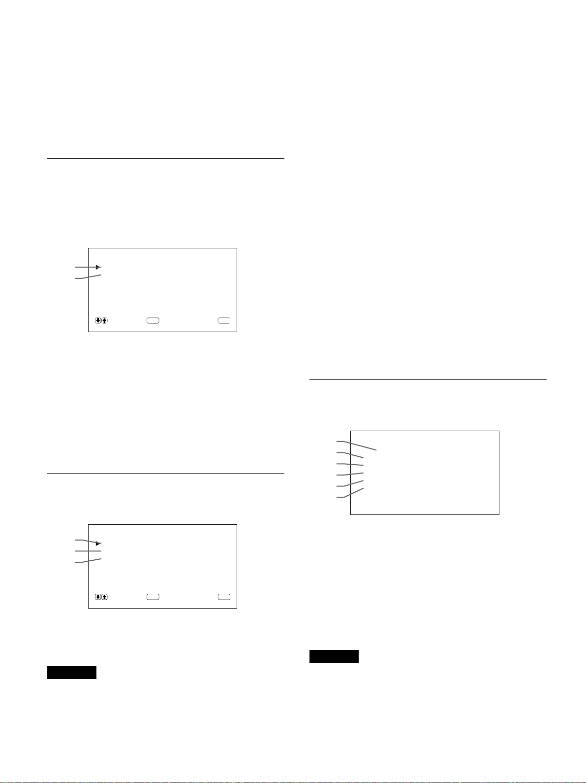
Utilisation des menus d’affichage
qh LANGUE
Sélectionnez l’une des cinq langues d’affichage à
l’écran.
Les langues disponibles sont les suivantes: anglais,
allemand, français, italien et espagnol.
Pour plus de détails sur la sélection de la langue
d’affichage, voir “Sélection de la langue d’affichage à
l’écran” à la page 26 (FR).
Menu MEMOIRE
Ce menu permet de sauvegarder et de rappeler les
réglages dans les menus CTRL IMAGE, TAILLE
IMAGE et CONFIG (uniquement pour AMPLIF et
FILTRE H).
MEMOIRE
qj
qk
Pour plus de détails, voir “Utilisation de la mémoire” à la
page 25 (FR).
CHARGER
SAUVER
SELECT ANNULER
ENTER
MENU
w; MODE TELECOM
Sélectionnez le mode de télécommande.
TV: Télécommande de moniteurs ou de téléviseurs
Sony
PROJ: Télécommande de projecteurs Sony
NON: Désactive la télécommande.
Pour plus de détails, voir “Utilisation de l’autre
télécommande” à la page 28 (FR).
wa TELECOM UNIQ
Sélectionnez OUI pour désactiver les touches de
commande frontales du moniteur. Le moniteur peut
uniquement être commandé au moyen de la
télécommande. Lorsque TELECOM UNIQ est sur
OUI, les indicateurs du panneau avant s’éteignent.
Pour désactiver le mode TELECOM UNIQ, réglez
TELECOM UNIQ sur OFF à l’aide de la
télécommande ou appuyez sur la touche CTRL tout en
maintenant le commutateur 1 enfoncé. Le moniteur
passe en mode de veille et le mode TELECOM UNIQ
est désactivé.
Le réglage de cette option reste sélectionné lorsque le
cordon d’alimentation secteur est débranché, mais est
désactivé si le moniteur est mis hors tension au moyen
de son commutateur d’alimentation.
qj CHARGER
Rappelle les réglages prédéfinis.
qk SAUVER
Sauvegarde les réglages.
Menu TELECOMMANDE
Ce menu sert au réglage de la télécommande.
ql
w;
wa
ql NO. INDEX
Définit le numéro de la télécommande.
Remarque
Lorsque vous définissez le numéro d’index, utilisez
les touches du moniteur.
Pour plus de détails sur le numéro d’index, voir
“Utilisation d’un moniteur spécifique avec la
télécommande” à la page 27 (FR).
TELECOMMANDE
NO. INDEX : 001
MODE TELECOM : TV
TE LECOM UN I Q : NON
SELECT ANNULER
ENTER
MENU
Menu STATUT
Ce menu sert à afficher l’état interne du moniteur.
ws
wd
wf
wg
wh
wj
ws Nom du modèle
Indique le nom du modèle.
wd NUM SERIE
Indique le numéro de série.
wf TEMPS FONCT
Indique les heures d’utilisation totales.
Remarque
Le mode de veille n’est pas comptabilisé dans les
heures d’utilisation.
wg LOGICIEL
Indique la version du logiciel système.
STATUT
[ PFM-510A1WE ]
NUM SERIE :2000001
TEMPS FONCT :000000H
LOGICIEL :
TEMPERATURE : OK
VENTI LATEUR : OK
Ver
1.00
18 (FR)
Page 49

Utilisation des menus d’affichage
wh TEMPERATURE
Indique si la température interne du moniteur est
habituelle.
OK: Habituelle
NG: Inhabituelle
Lorsque la température interne est inhabituelle, NG
s’affiche et l’option clignote en rouge. L’indicateur 1
du panneau de commande clignote également.
Remarque
Il se peut que le message “TEMPERATURE NG”
apparaisse lorsque les orifices de ventilation sont
obstrués ou lorsque le moniteur est installé dans un
endroit mal ventilé. Dans ce cas, vérifiez que les trous
de ventilation ne sont pas bloqués et installez le
moniteur dans une zone bien aérée. Si le message
reste affiché, consultez votre distributeur Sony agréé.
Lorsque l’indicateur 1 clignote ou NG s’affiche, voir
“Fonction d’auto-diagnostic” à la page 26 (FR).
wj VENTILATEUR
Des ventilateurs de refroidissement sont intégrés dans
ce moniteur. Cette option indique que les ventilateurs
de refroidissement fonctionnent correctement.
OK: Habituel
NG: Inhabituel
Lorsque les ventilateurs de refroidissement ne
fonctionnent pas comme d’habitude, NG s’affiche et
l’option clignote en rouge. L’indicateur 1 du panneau
de commande clignote également.
Remarque
Les ventilateurs de refroidissement supérieurs
détectent la température interne du moniteur et
commandent le régime des ventilateurs. Si la
température ambiante est trop élevée, le régime des
ventilateurs augmente et les bruits seront plus
importants.
Remarque
Lorsque le message “VENTILATEUR NG” apparaît,
consultez votre distributeur Sony agréé.
Lorsque l’indicateur 1 clignote ou NG s’affiche, voir
“Fonction d’auto-diagnostic” à la page 26 (FR).
Ventilateurs de refroidissement
Orifices de ventilation
19 (FR)
Page 50

Visualisation de l’image
Visualisation de l’image
Avant de commencer
•Mettez le moniteur sous tension.
•Mettez l’appareil raccordé sous tension et activez la
lecture d’une source vidéo.
•Pour afficher sur l’écran les informations du signal
entré au moment de la mise sous tension ou de la
commutation du signal d’entrée, réglez
“AFFICHAGE” dans le menu CONFIG sur OUI.
•Pour activer l’affichage de votre langue, voir page 26
(FR).
Commutation de l’image
1 Appuyez sur CTRL du panneau de commande du
moniteur.
Les touches RGB1, YUV, RGB2, LINE, et Y/C
s’allument.
Remarque
Nous recommandons d’utiliser comme source
d’entrée un appareil vidéo doté d’un correcteur de
base de temps (TBC). Si vous recevez le signal sans le
TBC, il se peut que l’image disparaisse en raison de
perturbations du signal de synchronisation.
Affichage du signal d’entrée et des
données d’état du moniteur
Le signal d’entrée et les données d’état du moniteur
sont affichées sur l’écran pendant environ cinq
secondes lorsque vous mettez le moniteur sous tension
ou lorsque vous commutez le signal d’entrée.
Pour désactiver la fonction, appliquez la procédure
suivante.
1 Appuyez sur MENU.
Le menu principal apparaît sur l’écran du
moniteur.
2 Sélectionnez la source d’entrée à afficher en
appuyant sur les touches suivantes.
RGB1:Sélectionne le signal audio et vidéo entré
par les connecteurs RGB1 lorsque le
signal d’entrée est un signal RVB.
YUV: Sélectionne le signal audio et vidéo entré
par les connecteurs RGB1 lorsque le
signal d’entrée est un signal composante.
RGB2:Sélectionne le signal audio et vidéo entré
par les connecteurs RGB2.
LINE: Sélectionne le signal audio et vidéo entré
par le connecteur VIDEO IN et la prise
AUDIO IN dans les connecteurs LINE.
Y/C: Sélectionne le signal audio et vidéo entré
par le connecteur Y/C IN et la prise
AUDIO IN dans les connecteurs LINE.
Système couleur ou fréquence horizontale/verticale
Type de
signal
PAL
LINE·Y/C
MENU PRINCIP
CTRL IMAGE
TAILLE IMAGE
CONF I G
MEMOIRE
TELECOMMANDE
STATUT
SELECT ANNULER
ENTER
MENU
2 Appuyez sur M/m pour déplacer le curseur (B) sur
“CONFIG” et appuyez sur ENT.
Le menu CONFIG apparaît sur l’écran du
moniteur.
CONF I G
AMPL I F : HAUT
F I LTRE H : AUTO
AFF ICHAGE : OUI
LANGUE
SELECT ANNULER
ENTER
MENU
3 Appuyez sur M/m pour déplacer le curseur (B) sur
“AFFICHAGE” et appuyez sur ENT.
Le menu suivant apparaît sur l’écran du moniteur.
Le signal d’entrée sélectionné apparaît sur l’écran
du moniteur.
Vous pouvez également commuter le signal
d’entrée au moyen de la télécommande.
20 (FR)
AFF ICHAGE : OU I
Page 51

Visualisation de l’image
4 Appuyez sur M pour mettre “AFFICHAGE” sur
NON et appuyez sur ENT.
La fonction AFFICHAGE est désactivée.
Pour activer la fonction d’information, mettez
“AFFICHAGE” sur OUI à l’étape 4 ci-dessus.
Remarque
Vous pouvez obtenir les informations d’entrée à
n’importe quel moment en appuyant sur la touche
DISPLAY de la télécommande, quel que soit le
réglage ci-dessus.
La liste d’information du signal d’entrée
Système couleur ou fréquence horizontale/verticale
31.5
kHz
/60
Type de
signal
RGB1 ·RVB
Hz
Affichage sur écran de l’état du moniteur
Affichage Signification
sur écran
31,5kHz / Le signal d’entrée sélectionné est un signal
60Hz (eg.) RVB informatique.
525 / 60 (eg.) Le signal d’entrée sélectionné est un signal
RVB ou vidéo composante.
NTSC Le signal d’entrée sélectionné est un signal
NTSC.
PAL Le signal d’entrée sélectionné est un signal
PAL.
AUTRES Le signal d’entrée est en-dehors de la plage
de saisie.
NO SYNC Il n’y a pas de signal d’entrée.
SUPPRES Le son est coupé.
RGB1 RVB Le mode de signal de RGB1 est réglé sur le
signal RVB.
RGB1 YUV Le mode de signal de RGB1 est mis sur
vidéo composante.
LINE COMP L’entrée vidéo composite est sélectionnée
sur LINE.
LINE Y/C L’entrée vidéo Y/C est sélectionnée sur
LINE.
Signal d’entrée Système couleur ou fréquence
NTSC NTSC
PAL PAL
VGAa) (Graphics) 31,5 kHz 60 Hz
VGA (Text) 31,5 kHz 70 Hz
HDTV 33,8 kHz 60 Hz
Macb) 13" 35,0 kHz 67 Hz
VESAc) 800×600 37,9 kHz 60 Hz
VESA 1024×768 48,4 kHz 60 Hz
Mac 16" 49,7 kHz 75 Hz
ATId) 1280×1024 64,0 kHz 60 Hz
Mac 21" 68,7 kHz 75 Hz
VESA 1280×1024 80,0 kHz 75 Hz
horizontale/verticale
a) VGA est une marque de commerce déposée de
International Business Machines Corporation, USA.
b) Mac (Macintosh) est une marque de commerce déposée
de Apple Computer, Inc.
c) VESA est une marque de commerce déposée deVideo
Electronics Standard Association.
d) ATI est une marque de commerce déposée de ATI
Technologies, Inc.
Remarque
Lors de l’entrée d’un signal HDTV, entrez le signal de
synchronisation à trois niveaux vers le connecteur G/Y IN.
21 (FR)
Page 52

Réglage de l’image
Réglage de l’image
Pendant que vous visionnez l’image, vous pouvez
régler le contraste, la luminosité, l’intensité des
couleurs et la phase à votre gré. Ces réglages peuvent
être exécutés séparément pour chacun des signaux
d’entrée. Vous pouvez également enregistrer vos
réglages dans la mémoire.
Réglage du contraste, de la
luminosité, de l’intensité des
couleurs et de la phase
Remarques
•Les commandes CHROMA et PHASE sont
inopérantes avec un signal RVB.
•La commande PHASE est inopérante avec un signal
composante.
•La commande PHASE est inopérante avec une
source de couleur PAL.
•Ne changez pas le niveau CHROMA/PHASE (NTSC
uniquement) si le signal sélectionné n’est pas un
signal NTSC ou PAL.
Bien qu’il n’ait aucun effet sur l’image actuelle, il
affectera l’image du signal NTSC ou PAL qui sera
entré ultérieurement.
Appuyez sur MENU de façon à ce que le menu
principal apparaisse sur l’écran du moniteur et
sélectionnez “CONTRASTE”, “LUMINOSITE”,
“CHROMA” ou “PHASE” dans le menu CTRL
IMAGE à l’aide des touches M/m.
CONTRASTE
Sélectionnez “CONTRASTE” à l’aide des touches
M/m et appuyez sur la touche ENT.
Ajustez le contraste à l’aide des touches M/m dans la
plage MIN (0) à MAX (+100).
M: pour augmenter le contraste de l’image
m: pour diminuer le contraste de l’image
LUMINOSITE
Sélectionnez “LUMINOSITE” à l’aide des touches
M/m et appuyez sur la touche ENT.
Ajustez la luminosité à l’aide des touches M/m dans la
plage MIN (–50) à MAX (+50).
M: pour rendre l’image plus verdâtre
m: pour rendre l’image plus rougeâtre
Restauration des réglages par
défaut des options du menu CTRL
IMAGE
1 Dans le menu CTRL IMAGE, appuyez sur M/m
pour déplacer le curseur (B) sur “REINITIAL” et
appuyez sur ENT.
Le menu suivant apparaît sur l’écran du moniteur.
REINITIAL : NON
SELECT ANNULER
ENTER
MENU
2 Appuyez sur M/m.
“NON” devient “OUI”.
REINITIAL : OUI
CHROMA
Sélectionnez “CHROMA” à l’aide des touches M/m et
appuyez sur la touche ENT.
Ajustez l’intensité des couleurs à l’aide des touches
M/m dans la plage MIN (–50) à MAX (+50).
M: pour augmenter l’intensité des couleurs
m: pour diminuer l’intensité des couleurs
PHASE
Sélectionnez “PHASE” à l’aide des touches M/m et
appuyez sur la touche ENT.
Ajustez la phase à l’aide des touches M/m dans la
plage MIN (–50) à MAX (+50).
M: pour rendre l’image plus verdâtre
m: pour rendre l’image plus rougeâtre
22 (FR)
SELECT ANNULER
ENTER
MENU
3 Appuyez sur ENT.
Les options du menu CTRL IMAGE sont
restaurées aux valeurs par défaut.
Pour annuler la fonction de réinitialisation, appuyez
sur la touche MENU avant d’appuyer sur la touche
ENT.
Page 53

Redimensionnement et positionnement de l’image
Redimensionnement et
positionnement de
l’image
Vous pouvez décaler la position de l’image de
manière à ce qu’elle s’adapte à l’écran, ou régler
séparément la taille verticale et horizontale de
l’image.
Réglage de la taille de l’image
1 Appuyez sur MENU.
Le menu principal apparaît sur l’écran du
moniteur.
MENU PRINC IP
CTRL IMAGE
TAILLE IMAGE
CONF I G
MEMOIRE
TELECOMMANDE
STATUT
SELECT ANNULER
ENTER
2 Appuyez sur M/m pour déplacer le curseur (B) sur
“TAILLE IMAGE” et appuyez sur ENT.
Le menu TAILLE IMAGE apparaît sur l’écran du
moniteur.
MENU
4 Appuyez sur M/m pour redimensionner l’image.
M: pour agrandir la taille horizontale
m: Pour réduire la taille horizontale
La taille horizontale de l’image est indiquée sur
l’écran du moniteur dans la plage MIN(–50) à
MAX(+50). La valeur par défaut est 00.
5 Appuyez sur ENT.
Le menu retourne au menu TAILLE IMAGE.
6 Appuyez sur M/m pour déplacer le curseur (B) sur
“AMPL V” et appuyez sur ENT.
Le menu suivant apparaît sur l’écran du moniteur.
AMPL V : 00
7 Appuyez sur M/m pour redimensionner l’image.
M: pour agrandir la taille verticale
m: pour réduire la taille verticale
La taille verticale de l’image est indiquée sur
l’écran du moniteur dans la plage MIN(–50) à
MAX(+50). La valeur par défaut est 00.
8 Appuyez sur ENT.
Le menu retourne au menu TAILLE IMAGE.
TAILLE IMAGE
AMPL H : 00
DEPL H : 00
AMPL V : 0 0
DEPL V : 00
FORMAT : 4 x3
REINITIAL
SELECT ANNULER
ENTER
MENU
3 Appuyez sur M/m pour déplacer le curseur (B) sur
“AMPL H” et appuyez sur ENT.
Le menu suivant apparaît sur l’écran du moniteur.
AMPL H : 00
Réglage de la position de l’image
1 Dans le menu TAILLE IMAGE, appuyez sur M/m
pour déplacer le curseur (B) sur “DEPL H” et
appuyez sur ENT.
Le menu suivant apparaît sur l’écran du moniteur.
DEPL H : 00
23 (FR)
Page 54

Redimensionnement et positionnement de l’image
2 Appuyez sur M/m pour décaler l’image.
M: pour décaler l’image vers la droite.
m: pour décaler l’image vers la droite.
La position horizontale de l’image est indiquée sur
l’écran du moniteur dans la plage MIN(–50) à
MAX(+50). La valeur par défaut est 00.
3 Appuyez sur ENT.
Le menu retourne au menu TAILLE IMAGE.
4 Appuyez sur M/m pour déplacer le curseur (B) sur
“DEPL V” et appuyez sur ENT.
Le menu suivant apparaît sur l’écran du moniteur.
DEPL V : 0 0
5 Appuyez sur M/m pour décaler l’image.
M: pour décaler l’image vers le haut.
m: pour décaler l’image vers le bas.
La position verticale de l’image est indiquée sur
l’écran du moniteur dans une plage MIN(–50) à
MAX(+50). La valeur par défaut est 00.
2 Appuyez sur M/m.
“NON” devient “OUI”.
REINITIAL : OUI
SELECT ANNULER
ENTER
MENU
3 Appuyez sur ENT.
La taille et la position d’origine de l’image sont
restaurées.
Pour annuler la fonction de réinitialisation, appuyez
sur la touche MENU avant d’appuyer sur la touche
ENT.
6 Appuyez sur ENT.
Le menu retourne au menu TAILLE IMAGE.
Restauration de la taille et de la
position originales de l’image
1 Dans le menu TAILLE IMAGE, appuyez sur M/m
pour déplacer le curseur (B) sur “REINITIAL” et
appuyez sur ENT.
Le menu suivant apparaît sur l’écran du moniteur.
REINITIAL : NON
SELECT ANNULER
ENTER
MENU
24 (FR)
Page 55

Utilisation de la mémoire
Vous pouvez sauvegarder les réglages actuels de
l’image pour chaque signal d’entrée à l’aide de la
fonction MEMOIRE.
Les réglages sauvegardés peuvent être rappelés à tout
moment.
Les options des menus CTRL IMAGE, TAILLE
IMAGE et CONFIG (uniquement pour AMPLIF et
FILTRE H) peuvent être mémorisés.
Vous pouvez sauvegarder les réglages de l’image pour
cinq signaux d’entrée.
Mémorisation des réglages
sélectionnés
Utilisation de la mémoire
Le message “TERMINE” apparaît pendant
environ cinq secondes.
Les réglages en cours sont enregistrés sous le
numéro de mémoire sélectionné.
Si des données sont déjà enregistrées sous le
numéro de mémoire sélectionné, le type de signal
et le système couleur ou la fréquence horizontale/
fréquence verticale apparaissent dans la colonne
située à droite du numéro de mémoire sélectionné.
Type de signal
Système couleur ou fréquence horizontale/verticale
SAUVER
MEM 1:RVB 31.5k
MEM 2 : V IDE
MEM 3 : V IDE
MEM 4 : V IDE
MEM 5 : V IDE
Hz
60
Hz
1 Appuyez sur MENU.
Le menu principal apparaît sur l’écran du
moniteur.
MENU PRINC IP
CTRL IMAGE
TAILLE IMAGE
CONF I G
MEMOIRE
TELECOMMANDE
STATUT
SELECT ANNULER
ENTER
MENU
2 Appuyez sur M/m pour déplacer le curseur (B) sur
“MEMOIRE” et appuyez sur ENT.
Le menu MEMOIRE apparaît sur l’écran du
moniteur.
MEMOIRE
CHARGER
SAUVER
SELECT ANNULER
ENTER
MENU
SELECT ANNULER
ENTER
MENU
Restauration des réglages sauvegardés
1 Dans le menu MEMOIRE, appuyez sur M/m pour
déplacer le curseur (B) sur “CHAGER” et
appuyez sur ENT.
Le menu suivant apparaît sur l’écran du moniteur.
CHAGER
MEM 1:RVB 31.5k 60
MEM 2 : V IDE
MEM 3 : V IDE
MEM 4 : V IDE
MEM 5 : V IDE
SELECT ANNULER
ENTER
HzHz
MENU
2 Appuyez sur M/m pour déplacer le curseur (B) sur
MEM 1 à 5 et appuyez sur ENT.
Le message “TERMINE” apparaît pendant
environ cinq secondes.
L’image est réglée suivant les réglages
sélectionnés.
3 Appuyez sur M/m pour déplacer le curseur (B) sur
“SAUVER” et appuyez sur ENT.
Le menu suivant apparaît sur l’écran du moniteur.
SAUVER
MEM 1 : V IDE
MEM 2 : V IDE
MEM 3 : V IDE
MEM 4 : V IDE
MEM 5 : V IDE
SELECT ANNULER
ENTER
MENU
4 Appuyez sur M/m pour déplacer le curseur (B) sur
MEM 1 à 5 et appuyez sur ENT.
Remarques
•Vous ne pouvez pas récupérer les données
mémorisées si le signal sélectionné est différent du
signal présélectionné.
•Les options suivantes peuvent être mémorisées:
Menu CTRL IMAGE
– CONTRASTE
– LUMINOSITE
– CHROMA
– PHASE
– TEMP COULEUR
– IMAGE AUTO
25 (FR)
Page 56

Utilisation de la mémoire / Sélection de la langue d’affichage à l’écran / Fonction d’auto-diagnostic
Menu TAILLE IMAGE
– AMPL H
– DEPL H
– AMPL V
– DEPL V
– FORMAT
Menu CONFIG
– AMPLIF
– FILTRE H
Sélection de la langue
d’affichage à l’écran
Vous pouvez sélectionner l’une des cinq langues
d’affichage proposées.
Il s’agit de l’allemand, l’anglais, l’espagnol, le
français et l’italien.
1 Appuyez sur MENU.
Le menu principal apparaît sur l’écran du
moniteur.
3 Appuyez sur M/m pour déplacer le curseur (B) sur
“LANGUE” et appuyez sur ENT.
Le menu suivant apparaît sur l’écran du moniteur.
LANGUE
ENGL I SH
DEUTSCH
FRANÇA I S
ITALIANO
ESPAÑOL
SELECT ANNULER
ENTER
MENU
4 Appuyez sur M/m pour déplacer le curseur (B) sur
la langue de votre choix et appuyez sur ENT.
La langue d’affichage que vous avez sélectionnée
est activée.
ENGLISH: anglais
DEUTSCH: allemand
FRANÇAIS: français
ITALIANO: italien
ESPAÑOL: espagnol
5 Appuyez sur MENU.
Le menu retourne au menu CONFIG.
MENU PRINCIP
CTRL IMAGE
TAILLE IMAGE
CONF I G
MEMOIRE
TELECOMMANDE
STATUT
SELECT ANNULER
ENTER
MENU
2 Appuyez sur M/m pour déplacer le curseur (B) sur
“CONFIG” et appuyez sur ENT.
Le menu CONFIG apparaît sur l’écran du
moniteur.
CONF I G
AMPL I F : HAUT
F I LTRE H : AUTO
AFF ICHAGE : OUI
LANGUE
SELECT ANNULER
ENTER
MENU
Fonction d’autodiagnostic
L’appareil est équipé d’une fonction d’autodiagnostic.
Cette fonction permet d’afficher l’état du moniteur par
le clignotement de l’indicateur 1 et au moyen de
chiffres sur l’indicateur SERVICE CODE. Ces
numéros vous indiquent l’état actuel du moniteur.
Lorsque l’appareil fonctionne normalement, seul le
point en bas à droite de l’indicateur SERVICE CODE
clignote.
Si l’indicateur 1 clignote, vérifiez le chiffre et
contactez votre distributeur Sony agréé.
1 Vérifiez le numéro à 2 chiffres de l’indicateur
SERVICE CODE.
L’indicateur affiche un numéro ou des numéros
multiples en alternance toutes les demi-secondes.
2 Débranchez l’appareil.
Communiquez le numéro à votre distributeur Sony
agréé.
26 (FR)
Page 57

ON
ID MODE
SET
OFF
Utilisation d’un moniteur spécifique avec la télécommande
Utilisation d’un moniteur
spécifique avec la
télécommande
A l’aide de la télécommande fournie, vous pouvez
exploiter un moniteur spécifique sans affecter d’autres
moniteurs qui seraient également installés.
1 Appuyez sur ID MODE ON de la télécommande.
Les numéros d’index du moniteur apparaissent en
caractères blancs sur tous les moniteurs. (Chaque
moniteur reçoit un numéro d’index prédéfini
individuel de 1 à 255.)
Voir “Pour modifier le numéro d’index” dans la colonne
à droite de cette page pour modifier le numéro d’index.
Numéro d’index
ON
SET
OFF
ID MODE
2 Entrez le numéro d’index du moniteur que vous
désirez exploiter à l’aide des touches 0 – 9 de la
télécommande.
Le numéro entré apparaît à droite de chaque
numéro d’index individuel du moniteur.
NO. INDEX 117 . ..
Numéro d’entrée
4 Après avoir effectué les réglages nécessaires,
appuyez sur ID MODE OFF.
Le moniteur revient au mode normal.
ON
SET
OFF
ID MODE
Pour modifier le numéro d’index
Vous pouvez modifier le numéro d’index si nécessaire.
Lorsque vous modifiez le numéro, utilisez les touches
du moniteur.
1 Appuyez sur MENU.
Le menu principal apparaît sur l’écran du
moniteur.
MENU PRINC IP
CTRL IMAGE
TAILLE IMAGE
CONF I G
MEMOIRE
TELECOMMANDE
STATUT
SELECT ANNULER
ENTER
MENU
2 Appuyez sur M/m pour déplacer le curseur (B) sur
“TELECOMMANDE” et appuyez sur ENT.
Le menu TELECOMMANDE apparaît sur l’écran
du moniteur.
NO. INDEX 117 117
10/0
2
1
4
7
3
5
6
8
9
3 Appuyez sur ID MODE SET.
Le caractère du moniteur sélectionné devient cyan
tandis que les autres deviennent rouges.
Vous pouvez utiliser uniquement un moniteur
spécifié. (Toutes les opérations sont disponibles en
mode ID sauf POWER ON/OFF.)
TELECOMMANDE
NO. INDEX : 001
MODE TELECOM : TV
TE LECOM I NIQ : NON
SELECT ANNULER
ENTER
MENU
3 Appuyez sur M/m pour déplacer le curseur (B) sur
“NO. INDEX” et appuyez sur ENT.
Le menu suivant apparaît sur l’écran du moniteur.
NO. INDEX : 001
4 Sélectionnez le numéro d’index à l’aide des
touches M/m et appuyez sur ENT.
Le menu retourne au menu TELECOMMANDE.
27 (FR)
Page 58

Utilisation de l’autre télécommande
Utilisation de l’autre
télécommande
Les opérations suivantes peuvent être commandées.
•Mise sous/hors tension
•Sélection de l’entrée
•Exploitation des menus
•Réglages d’image: contraste, phase et intensité des
couleurs
•Activation/désactivation de l’affichage sur écran
(uniquement pour les moniteurs vidéo et les
téléviseurs)
Les opérations et les touches disponibles à utiliser
pour chaque opération sont limitées en fonction de
chaque télécommande. Voir le tableau ci-dessous.
Modèles de télécommande RM-854 RM-1271 RM-PJ1292 RM-PJ1000
Réglage REMOTE MODE TV PJ PJ PJ
Sélection de l’entrée
Exploitation du menu
Réglage de l’image Contraste CONTRAST+/– CONTR+/– CONTR+/– CONTR+/–
Informations sur écran DISPLAY — STATUS ON STATUS ON
RGB1 RGB A A A
RGB2 — B B B
LINE LINE1 VIDEO VIDEO VIDEO
MENU MENU PAGE ou < PAGE ou < MENU ou <
ENTER ENTER ,,ENTER ou ,
++MMM
––mmm
Intensité des couleurs
Phase PHASE+/– HUE+/– HUE+/– HUE+/–
CHROMA+/– COLOR+/– COLOR+/– COLOR+/–
28 (FR)
Page 59

Spécifications
Traitement du signal vidéo
Plage de saisie Fréquence horizontale: 15,6 à
80 kHz
Fréquence verticale: 48 à 120 Hz
Signal présélectionné
Entrée: 12 formats (voir page
21 (FR))
Mémoire vidéo 1.152 × 1.152 × 24 bits (total
RVB)
Fréquence d’échantillonnage
Phase de décalage de 14,3 à 50
MHz max. (équivalant à un
échantillonnage de 100 MHz)
Système d’affichage
Panneau d’affichage à plasma de
type CA
Résolution d’affichage
1024 points × 1024 lignes
0,90 (
Pixel
Taille de l’image
Taille du panneau 42 pouces (diagonale 1.058 mm)
horizontal
mm
921 (horizontal) × 522 (vertical)
mm
Entrées et sorties
) × 0,51 (vertical)
Spécifications
RGB2
RGB IN D-sub à 15 broches
Voir “Attribution des broches” à la
page 30 (FR).
AUDIO IN (L, R) Prise phono (×2)
500 mVrms, haute impédance
LINE (NTSC, PAL)
VIDEO IN Type BNC (×1)
Vidéo composite, 1 Vcc ±2 dB
synchro négative, 75 ohms
(terminaison automatique)
Y/C IN Type mini DIN à 4 broches (×1)
Y (luminance): 1 Vcc ±2 dB
synchro négative, 75 ohms
(terminaison automatique)
C (chrominance): Salve 0,286 Vcc
±2 dB (NTSC), 75 ohms
(terminaison automatique)
Salve 0,3 Vcc ±2 dB (PAL)
75 ohms (terminaison
automatique)
AUDIO IN (L, R) Prise phono (×2)
500 mVrms, haute impédance
VIDEO OUT Type BNC (×1) boucle directe
Y/C OUT Type mini DIN à 4 broches (×1)
boucle directe
AUDIO OUT (L, R) (sortie variable)
Prise phono (×2) boucle directe
RGB1
R (R-Y)/ G (Y)/B (B-Y) IN
Type BNC (×3)
0,714 Vcc/non composite 75 ohms
(terminaison automatique)
1 Vcc/composite 75 ohms
(terminaison automatique)
SYNC IN(HD/COMP, VD)
Type BNC (×2)
H (ou composite) SYNC,
V SYNC,
1 à 5 Vcc haute impédance
AUDIO IN (L, R) Prise phono (×2)
500 mVrms, haute impédance
R (R-Y)/ G (Y)/B (B-Y) OUT
Type BNC (×3) boucle directe
SYNC OUT (HD/COMP, VD)
Type BNC (×2) boucle directe
H (ou composite) SYNC,
V SYNC
AUDIO OUT (L, R)
Prise phono (×2) boucle directe
MONITOR OUT AUDIO (L, R)
Prise phono (×2)
Maximum 500 mVrms, haute
impédance
CONTROL S (IN, OUT)
Mini prise (stéréo) (×2)
5 Vcc
REMOTE (RS-232C)
Miniconnecteur DIN à 8 broches
(×1)
SPEAKERS 6 à 16 ohms, 7 W + 7 W (lorsque
l’impédance est de 8 ohms)
Généralités
Puissance de raccordement
100 à 120 V CA, 50/60 Hz, 4,7 A/
410 W
220 à 240 V CA, 50/60 Hz, 2,2 A/
400 W
29 (FR)
Page 60

Spécifications
Conditions d’utilisation
Température: 0 à 35°C
Humidité: 20 à 90 % (sans
condensation)
Pression atmosphérique: 700 à
1060 mbar
Conditions de stockage/transport
Température: –10 à 40°C
Humidité: 20 à 90 % (sans
condensation)
Pression atmosphérique: 700 à
1060 mbar
Dimensions 1036 × 636 × 152 mm
(l/h/p)
Masse 45 kg (99 lb 3 oz)
Accessoires fournis
Cordon d’alimentation secteur (1)
Support de prise secteur (1)
Télécommande RM-921 (1)
Piles R6 (AA) (2)
Tore de ferrite (2)
Support de fixation de pied (2)
Vis de support de fixation de pied
(6)
Stabilisateur de moniteur (2)
Mode d’emploi (1)
La conception et les spécifications sont sujettes à
modifications sans préavis.
Connecteur RGB IN (D-sub à 15 broches)
N° de broche Signal
1 Vidéo rouge ou R-Y
2 Vidéo vert ou Y
3 Vidéo bleu ou B-Y
4 Masse
5 Masse
6 Masse du rouge
7 Masse du vert
8 Masse du bleu
9 Non utilisé
10 Masse
11 Masse
12 SDA
13 Sync H ou sync composite
14 Sync V
15 SCL
Attribution des broches
Prise Y/C (mini DIN à 4 broches)
Chrominance
GND
Luminance
GND
30 (FR)
Page 61

31 (FR)
Page 62

ACHTUNG
Um Feuergefahr und die Gefahr eines
elektrischen Schlags zu vermeiden, setzen Sie
das Gerät weder Regen noch sonstiger
Feuchtigkeit aus.
Im Inneren des Geräts liegen gefährlich hohe
Spannungen an. Öffnen Sie daher das
Gehäuse nicht. Überlassen Sie
Wartungsarbeiten stets nur qualifiziertem
Fachpersonal.
Für Kunden in Europa
Dies ist eine Einrichtung, welche die Funk-Entstörung nach
Klasse A besitzt. Diese Einrichtung kann im Wohnbereich
Funkstörungen verursachen; in diesem Fall kann vom
Betreiber verlangt werden, angemessene Maßnahmen
durchzuführen und dafür aufzukommen.
Für Kunden in Deutschland
Dieses Gerät ist nur für den Gebrauch in Gewerbe und
Leichtiudustrie bestimmt. Es entspricht der Klasse A, es
erfüllt nicht die Grenzwerte der Klasse B.
Hinweis
Wenn Sie einen Computer an diesen Monitor
anschließen, müssen Sie die mitgelieferten
Ferritkerne anbringen. Andernfalls entspricht dieser
Monitor nicht den obligatorischen FCC/IC/CEStandards (EN55022).
Anbringen der Ferritkerne
Bringen Sie die Ferritkerne an beiden Enden des
Netzkabels an. Schließen Sie den Deckel fest, bis die
Klammern mit einem Klicken einrasten.
oder
Klammern
2 (DE)
Page 63

Inhalt
Sicherheitsmaßnahmen ............................................4 (DE)
Merkmale und Funktionen ........................................5 (DE)
Lage und Funktion der Teile und Bedienelemente 6 (DE)
Vorderseite / Seiten...................................................6 (DE)
Bedienfeld .................................................................7 (DE)
Rechtes Anschlußfeld ...............................................8 (DE)
Linkes Anschlußfeld ...............................................10 (DE)
Fernbedienung RM-921 ..........................................10 (DE)
Aufstellen des Monitors..........................................12 (DE)
Die versenkbaren Füße ...........................................12 (DE)
Vorsicht...................................................................13 (DE)
Anschließen des Monitors......................................14 (DE)
Anschließen des Netzkabels ...................................14 (DE)
Anschlußbeispiel.....................................................14 (DE)
Die Bildschirmmenüs..............................................16 (DE)
Arbeiten mit den Menüs .........................................16 (DE)
Übersicht über die Menüs .......................................16 (DE)
Die Anzeigefunktionen............................................20 (DE)
Auswählen des Bildes .............................................20 (DE)
Anzeige von Eingangssignal und Monitorstatus ....20 (DE)
Einstellen der Bildqualität ......................................22 (DE)
Einstellen von Kontrast, Helligkeit, Farbe und
Phase ..................................................................22 (DE)
Zurücksetzen der Optionen im Menü BILDEINST
auf die ursprünglichen Werte.............................22 (DE)
Einstellen von Bildgröße und Bildposition ...........23 (DE)
Einstellen der Bildgröße .........................................23 (DE)
Einstellen der Bildposition......................................23 (DE)
Zurücksetzen von Bildgröße und -position auf die
ursprünglichen Werte.........................................24 (DE)
Der Speicher ............................................................25 (DE)
Speichern der aktuellen Einstellungen....................25 (DE)
Aufrufen der gespeicherten Einstellungen..............25 (DE)
Auswählen der Menüsprache.................................26 (DE)
Selbstdiagnosefunktion..........................................26 (DE)
Steuern eines bestimmten Monitors über die
Fernbedienung ....................................................27 (DE)
Verwenden einer anderen Fernbedienung............28 (DE)
Technische Daten....................................................29 (DE)
DE
Deutsch
3 (DE)
Page 64

Sicherheitsmaßnahmen
Sicherheitsmaßnahmen
Sicherheit
•Betreiben Sie das Gerät an 100 bis 120 V
Wechselstrom oder 220 bis 240 V Wechselstrom.
•Das Typenschild mit Betriebsspannung,
Leistungsaufnahme usw. befindet sich an der
Geräterückseite.
•Sollten Fremdkörper oder Flüssigkeiten in das
Gehäuse gelangen, trennen Sie das Gerät von der
Netzsteckdose. Lassen Sie das Gerät von
qualifiziertem Fachpersonal überprüfen, bevor Sie es
wieder benutzen.
•Wollen Sie das Gerät einige Tage oder länger nicht
benutzen, ziehen Sie den Netzstecker aus der
Steckdose.
•Um das Gerät vom Netzstrom zu trennen, ziehen Sie
den Netzstecker aus der Netzsteckdose. Ziehen Sie
nicht am Kabel.
•Wenn der Monitor auf dem Boden aufgestellt wird,
verwenden Sie bitte unbedingt die versenkbaren
Füße.
Reinigung
Damit das Gerät immer wie neu aussieht, reinigen Sie
es regelmäßig mit einem milden Reinigungsmittel.
Verwenden Sie keine Lösungsmittel wie Verdünner
oder Benzin und keine Scheuermittel, da sie die
Gehäuseoberfläche angreifen. Trennen Sie zur
Sicherheit das Gerät vor dem Reinigen von der
Stromversorgung.
Verpacken
Werfen Sie den Karton und das Verpackungsmaterial
nicht weg. Sie eignen sich ideal zum Transportieren
des Geräts. Wenn Sie das Gerät an einen anderen Ort
transportieren müssen, verpacken Sie es wieder so,
wie auf dem Karton dargestellt.
Wenn Sie Fragen zu dem Gerät haben, wenden Sie
sich bitte an einen autorisierten Sony-Händler.
Aufstellung
•Achten Sie auf ausreichende Luftzufuhr, damit sich
im Gerät kein Wärmestau bildet. Stellen Sie das
Gerät nicht auf Oberflächen wie Teppichen oder
Decken oder in der Nähe von Materialien wie
Gardinen und Wandbehängen auf, die die
Lüftungsöffnungen blockieren könnten.
•Stellen Sie das Gerät nicht in der Nähe von
Wärmequellen wie Heizkörpern oder
Warmluftauslässen oder an Orten auf, an denen es
direktem Sonnenlicht, außergewöhnlich viel Staub,
mechanischen Vibrationen oder Stößen ausgesetzt
ist.
•Wenn Sie mehrere andere Geräte an dieses Gerät
anschließen, kann es je nach Standort dieses Geräts
und der anderen Geräte zu folgenden Störungen
kommen: Fehlfunktionen der Fernbedienung,
Bildstörungen und Tonstörungen.
Plasmabildschirm
•Auf dem Plasmabildschirm sind möglicherweise
kleine schwarze und/oder helle Bildpunkte zu sehen.
Dies ist normal.
•Lassen Sie nicht für lange Zeit dasselbe Standbild
ununterbrochen anzeigen. Andernfalls kann auf
einem Bereich des Bildschirms ein Nachbild zu
sehen sein. Aktivieren Sie in einem solchen Fall
einen Bildschirmschoner, damit die Anzeige
wechselt.
4 (DE)
Page 65

Merkmale und Funktionen
Die Geräte der Serie PFM-510A1W sind 16:9Flachmonitore (42 Zoll) mit einem Plasmabildschirm.
Dank des integrierten Bildrasterwandlers sind sie für
verschiedene Signaltypen geeignet.
Verbesserte Bildqualität
Mit dem Plasmabildschirm erzielen Sie bei 1024 ×
1024 Zeilen eine höhere Bildqualität. Dies ermöglicht
bei HDTV- und PC-Bildern eine höhere Detailschärfe.
Helligkeit und Kontrast sind gegenüber
herkömmlichen Monitoren stärker.
Interner Hochleistungsbildrasterwandler
Der Monitor verfügt über einen
Hochleistungsbildrasterwandler. Dank eines
speziellen Algorithmus kann der Monitor Signale in
vielfältigen Formaten verarbeiten – Video-, HDTV-,
PC-Signale usw.
Flexibilität
Ein Steckplatz dient als Reserve für zukünftige
Erweiterungen.
Mit dem Adapter für den Steckplatz sind schnelle und
problemlose Systemaktualisierungen möglich.
Merkmale und Funktionen
Weitere Funktionen
•Drei Gruppen von Video-/Audioeingängen: FBASbzw. Y/C-Eingang, RGB-Eingang, RGB-/
Farbdifferenzsignaleingang.
•Zeigt das HDTV-Signal mit dreistufigem
Synchronisationssignal an.
•Dreidimensionaler Kammfilter für die Trennung der
Y/C-Signale bei NTSC.
•Zeilenkorrelationskammfilter für die Trennung der
Y/C-Signale bei PAL.
•Automatische Eingangssignalerkennung mit
Anzeige.
•Kompatibel mit PnP (Plug and Play) von
1)
Windows95/98
.
•AGC-Bildfunktion — mit dieser Funktion wird der
Kontrast automatisch eingestellt und verbessert,
wenn ein schwaches Signal eingeht.
•Bildschirmmenü für verschiedene Einstellungen und
Anpassungen
•Benutzerfreundliche Bildschirmmenüs in fünf
Sprachen.
•Feineinstellung von Bildgröße und -position
•Speicher für bis zu fünf Bildeinstellungen.
•ID-Steuerung
•Selbstdiagnosefunktion.
•Anschluß REMOTE (RS-232C) (Mini-DIN, 8polig)
•Control-S-Anschluß
•Kann mit Infrarot- oder Kabelfernbedienung von
Sony eingesetzt werden, sofern diese mit dem
SIRCS-Code arbeitet.
•Vertikale Konfiguration
Warnhinweis zum Netzanschluß
Verwenden Sie das für die Stromversorgung in Ihrem Land geeignete Netzkabel.
USA, Kontinental- Großbritannien, Irland, Japan
Kanada europa Australien, Neuseeland
Steckertyp VM0033B COX-07 636 — VM1296
Weibliches Ende VM0113 COX-02 VM0310B VM0303B VM1313
Kabeltyp SJT H05VV-F CEE (13) 53rd (O.C) HVCTF
Mindestwerte (Kabel) 13A/125V 10A/250V 10A/250V 10A/125V
Sicherheitszertifizierung UL/CSA VDE VDE DENTORI
.........................................................................................................................................................................................................
1) Windows95/98 ist ein eingetragenes Warenzeichen der Microsoft Corporation.
5 (DE)
Page 66

Lage und Funktion der Teile und Bedienelemente
Lage und Funktion der
Teile und Bedienelemente
Vorderseite / Seiten
Vorderseite
6 Rechte Anschlußfeldabdeckung
Öffnen Sie diese Abdeckung, wenn Sie das rechte
Anschlußfeld benutzen.
Hinweise zum Öffnen der Anschlußfeldabdeckung finden
Sie unten auf dieser Seite.
So öffnen Sie die Anschlußfeldabdeckung
Lösen Sie die Schrauben, indem Sie sie gegen den
Uhrzeigersinn drehen, und öffnen Sie die Abdeckung.
Linke Seite
3
1
Rechte Seite
4
2
6
5
1 Versenkbare Füße
Dienen zum Aufstellen des Monitors auf dem Boden.
Näheres zu den versenkbaren Füßen finden Sie unter “Die
versenkbaren Füße” auf Seite 12(DE).
2 Bedienfeld
Einzelheiten zum Bedienfeld finden Sie unter “Bedienfeld”
auf Seite 7(DE).
3 Linke Anschlußfeldabdeckung
Öffnen Sie diese Abdeckung, wenn Sie das linke
Anschlußfeld benutzen.
An der Innenseite dieser Abdeckung können Sie die
Fernbedienung anbringen.
Hinweise zum Öffnen der Anschlußfeldabdeckung finden
Sie rechts auf dieser Seite.
So nehmen Sie die
Anschlußfeldabdeckung ab
Lösen Sie die Schrauben wie in der Abbildung unten
dargestellt, und nehmen Sie die
Anschlußfeldabdeckung ab.
Schrauben
So bringen Sie die Fernbedienung in der
Anschlußfeldabdeckung an
Bringen Sie die Fernbedienung wie in der Abbildung
unten dargestellt an der Innenseite der linken
Anschlußfeldabdeckung an.
Fernbedienung
4 Linkes Anschlußfeld
Einzelheiten zum linken Anschlußfeld finden Sie unter
“Linkes Anschlußfeld” auf Seite 10(DE).
5 Rechtes Anschlußfeld
Einzelheiten zum rechten Anschlußfeld finden Sie unter
“Rechtes Anschlußfeld” auf Seite 8(DE).
6 (DE)
Hinweis
Wenn Sie die Fernbedienung anbringen, achten Sie
darauf, daß die Oberseite der Fernbedienung nach
oben und die Rückseite nach außen weist.
Page 67

Bedienfeld
Lage und Funktion der Teile und Bedienelemente
VOL – VOL + MENU ENT RGB1 YUV RGB2 LINE Y/C CTRL
qd qs qa 0 98765 4 32 1
mM
1 Fernbedienungsdetektor
Hier geht das Signal von der Fernbedienung ein.
2 Schalter 1 (Bereitschaft)/Anzeige 1
(Bereitschaft)
Zum Einschalten des Monitors. Durch erneutes
Drücken schalten Sie wieder in den
Bereitschaftsmodus.
Die Anzeige 1 (Bereitschaft) leuchtet im
Bereitschaftsmodus rot auf.
Wenn die Anzeige 1 blinkt, schlagen Sie unter
“Selbstdiagnosefunktion” auf Seite 26(DE) nach.
3 Netzanzeige
Leuchtet auf, wenn der Monitor eingeschaltet wird.
4 Taste CTRL (Steuerung)
Wenn Sie die Tasten auf dem Bedienfeld verwenden
wollen, müssen Sie zuerst diese Taste drücken. Die
anderen Tasten leuchten dann auf oder blinken und
sind damit bereit. Drücken Sie die Taste nochmals,
um die anderen Tasten zu deaktivieren.
1
9 Taste RGB1
Zum Auswählen des RGB-Signals, das über die
RGB1-Anschlüsse eingespeist wird.
0 Taste ENT (Eingabe)
Zum Auswählen der gewünschten Option in einem
Menü.
qa Tasten M/m
Zum Bewegen des Cursors (B) zu einer Option bzw.
zum Einstellen eines Werts in einem Menü.
qs Taste MENU
Zum Aufrufen des Menüs.
qd Tasten VOL (Lautstärke) +/–
Mit der Taste + erhöhen Sie die Lautstärke, mit der
Taste – verringern Sie sie.
Hinweis
Die Tasten (außer dem Schalter 1 (Bereitschaft) 2)
auf dem Bedienfeld funktionieren nur, wenn Sie zuvor
die Taste CTRL drücken.
5 Taste Y/C
Zum Auswählen des über den LINE-Anschluß Y/C IN
eingespeisten Signals.
6 Taste LINE
Zum Auswählen des über den LINE-Anschluß
VIDEO IN eingespeisten Signals.
7 Taste RGB2
Zum Auswählen des Signals, das über die RGB2Anschlüsse eingespeist wird.
8 Taste YUV
Zum Auswählen des Farbdifferenzsignals, das über
die RGB1-Anschlüsse eingespeist wird.
7 (DE)
Page 68

Lage und Funktion der Teile und Bedienelemente
Rechtes Anschlußfeld
RGB 1
IN OUT
R
R-Y
G
Y
B
B-Y
1
2
3
Hinweis
Die Bildverbesserung für Videosignale (NTSC, PAL)
funktioniert nur bei FBAS- (Y/C) oder
Farbdifferenzsignalen (Y/R-Y/B-Y).
Das Bild vom RGB-Eingang kann verschwommen
erscheinen. Dabei handelt es sich nicht um eine
Fehlfunktion.
HD/
COMP
VD
L
R
RGB 2
RGB IN
L
R
VIDEO
Y/C
L
R
IN OUT
LINE
REMOTE
(RS-232C)
4
SYNC
AUDIO
AUDIO IN
5
AUDIO
6
1 RGB1 IN-Anschlüsse
R (R-Y)/G (Y)/B (B-Y) IN (BNC-Anschlüsse):
Eingang für ein analoges RGB- oder
Farbdifferenzsignal. Zum Anschließen an den
RGB- oder Farbdifferenzsignalausgang (Y/B-Y/RY) eines Computers oder Videogeräts.
Mit diesem Gerät können Sie auch ein analoges
HD-Farbdifferenzsignal (Y/P
Speisen Sie das P
und das P
R
B
-Signal am Anschluß B (B-Y) IN
-Signal am Anschluß R (R-Y) IN ein.
B/PR
) einspeisen.
HD/COMP IN (BNC-Anschluß): Eingang für ein
H-Synchronisationssignal oder ein zusammengesetztes
Synchronisationssignal. Zum Anschließen an den
Ausgang für das H-Synchronisationssignal oder das
zusammengesetzte Synchronisationssignal eines
Computers oder Videogeräts.
VD IN (BNC-Anschluß): Eingang für ein V-
Synchronisationssignal. Zum Anschließen an den
Ausgang für das V-Synchronisationssignal eines
Computers oder Videogeräts.
Das externe Synchronisationssignal wird
automatisch ausgewählt. Sehen Sie dazu in der
Tabelle unten nach.
Eingang
HD/COMP IN
VD IN V-Sync. — —
G(Y) IN
Ausgewähltes
Synchronisationssignal
Eingespeistes
Synchronisationssignal
H-Sync. Zusammen- —
gesetzt
Grün mit Sync. Grün mit Sync.Grün mit Sync.
H-Sync. Zusammen-
Grün mit Sync.
V-Sync. gesetzt
AUDIO IN (L/R) (Cinchbuchsen): Eingang für das
Audiosignal. Zum Anschließen an den
Audioausgang eines Computers oder Videogeräts.
Wenn das Audiosignal monaural ist, verbinden
Sie diese Buchse bitte mit dem linken (L)
Audiokanal.
2 RGB2 IN-Anschlüsse
RGB IN (D-sub 15polig): Zum Anschließen an den
RGB-Signalausgang eines Computers.
AUDIO IN (L/R) (Cinchbuchsen): Eingang für das
Audiosignal. Zum Anschließen an den
Audioausgang eines Computers. Wenn das
Audiosignal monaural ist, verbinden Sie diese
Buchse bitte mit dem linken (L) Audiokanal.
8 (DE)
3 LINE IN-Eingänge
VIDEO IN (BNC-Anschluß): Zum Anschließen an
den FBAS-Signalausgang eines Videogeräts.
Y/C IN (Mini-DIN, 4polig): Zum Anschließen an
den Y/C-Signalausgang eines Videogeräts.
AUDIO IN (L/R) (Cinchbuchsen): Zum
Anschließen an den Audioausgang eines
Videogeräts. Wenn das Audiosignal monaural ist,
verbinden Sie diese Buchse bitte mit dem linken
(L) Audiokanal.
Page 69

Lage und Funktion der Teile und Bedienelemente
4 RGB1 OUT-Anschlüsse
Diese Anschlüsse dienen als Durchschleifausgänge
für die RGB1 IN-Anschlüsse 1.
Wenn ein Kabel an die RGB OUT-Anschlüsse
angeschlossen ist, wird der 75-OhmAbschlußwiderstand der RGB IN-Anschlüsse
aufgehoben, und das über die RGB IN-Anschlüsse
eingespeiste Signal wird an diesen Anschlüssen
ausgegeben.
R (R-Y)/G (Y)/B (B-Y) OUT (BNC-Anschlüsse):
Durchschleifausgänge der RGB IN-Anschlüsse.
Zum Anschließen an den RGB- oder
Farbdifferenzsignaleingang (Y/B-Y/R-Y) eines
anderen Monitors.
HD/COMP OUT (BNC-Anschluß):
Durchschleifausgang des Anschlusses HD/COMP
IN. Zum Anschließen an den Eingang für das HSynchronisationssignal oder das
zusammengesetzte Synchronisationssignal eines
anderen Monitors.
VD OUT (BNC-Anschluß): Durchschleifausgang
des Anschlusses VD IN. Zum Anschließen an den
Eingang für das V-Synchronisationssignal eines
anderen Monitors.
AUDIO OUT (L/R) (Cinchbuchsen):
Durchschleifausgänge für die AUDIO INBuchsen. Zum Anschließen an die
Audioeingänge eines anderen Monitors oder
Videogeräts.
6
Anschluß REMOTE (RS-232C) (Mini-DIN, 8polig)
Mit diesem Anschluß können Sie den Monitor über
das RS-232C-Protokoll fernsteuern. Näheres dazu
erfahren Sie bei Ihrem autorisierten Sony-Händler.
Hinweis
Die Anschlüsse HD/COMP OUT und VD OUT sind
Hochimpedanzausgänge.
Wenn Sie diese Ausgänge benutzen, schließen Sie
einen Monitor mit
Hochimpedanzsynchronisationseingang an.
Andernfalls wird aufgrund der Diskrepanz beim
Synchronisationssignalpegel unter Umständen ein
oszillierendes oder gar kein Bild angezeigt.
AUDIO OUT (L/R) (Cinchbuchsen):
Durchschleifausgänge für die AUDIO INBuchsen. Zum Anschließen an die
Audioeingänge eines anderen Monitors.
5 LINE OUT-Anschlüsse
Diese Anschlüsse dienen als Durchschleifausgänge
für die LINE IN-Anschlüsse 3.
Wenn ein Kabel an den Anschluß VIDEO OUT oder
die Buchse Y/C OUT angeschlossen ist, wird der 75Ohm-Abschlußwiderstand des Anschlusses VIDEO
IN bzw. der Buchse Y/C IN aufgehoben, und das über
die Buchsen VIDEO IN oder Y/C IN eingespeiste
Signal wird am Anschluß VIDEO OUT oder an der
Buchse Y/C OUT ausgegeben.
VIDEO OUT (BNC-Anschluß): Zum Anschließen
an den FBAS-Signaleingang eines anderen
Monitors oder Videogeräts.
Y/C OUT (Mini-DIN, 4polig): Zum Anschließen an
den Y/C-Signaleingang eines anderen Monitors
oder Videogeräts.
9 (DE)
Page 70

Lage und Funktion der Teile und Bedienelemente
Linkes Anschlußfeld
MONITOR OUT
AUDIO
RL
VARIABLE
CONTROL S
IN
SPEAKERS
(6-16 Ω)
+
R–
SERVICE CODE
8.8.
OUT
Hinweise
•Wenn Sie die Buchse CONTROL S IN mit der
Buchse CONTROL S OUT am anderen Gerät
verbinden, können Sie den Monitor nicht mit der
1
Fernbedienung steuern.
•Sie können ein Stereokabel mit Ministecker statt des
Control-S-Kabels benutzen.
2
3 Lautsprecheranschlüsse SPEAKERS L/R
Zum Anschließen von Lautsprechern mit einer
Impedanz von 6 bis 16 Ohm.
+
L
3
–
Hinweis
Schließen Sie das Lautsprecherkabel nicht gleichzeitig
an den Monitor und an einen Verstärker an.
Andernfalls kann Überlaststrom vom Verstärker
eingespeist werden und den Monitor beschädigen.
4
4 Anzeige SERVICE CODE
Diese Anzeige ist nur für qualifiziertes Fachpersonal
bestimmt.
5
AC IN
1 Buchsen MONITOR OUT AUDIO (L/R)
(Cinchbuchsen)
Zum Ausgeben der Signale, die an den Buchsen
AUDIO IN eingespeist werden. Zum Anschließen an
die Audioeingänge eines Audioverstärkers (nicht
mitgeliefert).
Hinweis
Diese Buchsen sind variable Ausgänge. Wenn Sie den
Lautstärkeregler in die maximale Position stellen,
wird der Ausgangspegel auf 500 mV effektiver
Mittelwert eingestellt.
2 Buchsen CONTROL S IN/OUT (Minibuchsen)
Zum Anschließen an die Buchsen CONTROL S von
Videogeräten oder anderen Monitoren. Sie können
dann alle Geräte gleichzeitig mit einer einzigen
Fernbedienung steuern.
Wenn Sie ein Gerät steuern wollen, indem Sie die
mitgelieferte Fernbedienung auf den
Fernbedienungsdetektor des Monitors richten, verbinden
Sie die Buchse CONTROL S OUT des Monitors mit der
Buchse CONTROL S IN des anderen Geräts.
10 (DE)
5 Netzbuchse -AC IN
Schließen Sie das mitgelieferte Netzkabel an diese
Buchse und an eine Netzsteckdose an. Sobald Sie das
Netzkabel angeschlossen haben, wechselt der Monitor
in den Bereitschaftsmodus.
Fernbedienung RM-921
1
2
3
4
5
6
7
8
9
0
qa
MUTING
RGB1
LINE
1
4
7
10/0
STILL
POWER
ON
OFF
ON
SET
OFF
ID MODE
DISPLAY
RGB2
Y/C
2
5
8
ZOOM
SELECT
VOL
POWER
YUV
MTS/MPX
3
6
9
CH
DEGAUSS
MENU
ENTER
CH
qs
qd
qf
qg
qh
qj
qk
ql»
w;…
wa
Page 71

Lage und Funktion der Teile und Bedienelemente
1 Netzschalter POWER
Zum Einschalten des Monitors. Durch erneutes
Drücken schalten Sie wieder in den
Bereitschaftsmodus.
Hinweis
Wenn Sie mehrere Monitore benutzen, schalten Sie
mit diesem Schalter bereits eingeschaltete Monitore in
den Bereitschaftsmodus, und Monitore, die sich im
Bereitschaftsmodus befinden, werden eingeschaltet.
2 Taste MUTING
Zum Stummschalten des Tons. Wenn Sie nochmals
diese Taste oder die Taste VOL (Lautstärke) +/–
drücken, ist der Ton wieder zu hören.
3 Tasten RGB1/RGB2
Zum Auswählen des Eingangssignals von den RGB1oder RGB2-Anschlüssen.
4 Taste LINE
Zum Auswählen des über den LINE-Anschluß
VIDEO IN eingespeisten Signals.
qa ID MODE-Tasten (ON/SET/OFF)
Wenn Sie die Taste ON drücken, erscheint eine
Indexnummer auf dem Bildschirm. Geben Sie dann
die Indexnummer des Monitors ein, den Sie bedienen
wollen, und drücken Sie die Taste SET. Danach
schalten Sie mit der Taste OFF wieder in den
normalen Modus.
qs Taste DISPLAY
Zum Anzeigen von Informationen zum
Eingangssignal oben auf dem Monitorbildschirm.
Drücken Sie die Taste nochmals, wenn Sie die
Informationen wieder ausblenden wollen.
qd Taste YUV
Zum Auswählen des Farbdifferenzsignals, das über
die RGB1-Anschlüsse eingespeist wird.
qf Taste MTS/MPX
Diese Taste hat bei diesem Monitor keine Funktion.
qg Taste CH
Diese Taste hat bei diesem Monitor keine Funktion.
5 Taste Y/C
Zum Auswählen des über den LINE-Anschluß Y/C IN
eingespeisten Signals.
6 Zahlentasten
Dienen zum Eingeben der Indexnummer.
7 Taste ZOOM
Diese Taste hat bei diesem Monitor keine Funktion.
8 Taste STILL
Diese Taste hat bei diesem Monitor keine Funktion.
9 Schalter POWER ON
Zum Einschalten des Monitors. Wenn Sie mit
mehreren Monitoren arbeiten und diesen Schalter statt
des Netzschalters POWER 1 verwenden, werden
andere Monitore, die bereits eingeschaltet sind, nicht
ausgeschaltet.
0 Schalter POWER OFF
Mit diesem Schalter wird der Monitor in den
Bereitschaftsmodus geschaltet. Wenn Sie mit
mehreren Monitoren arbeiten und diesen Schalter statt
des Netzschalters POWER 1 verwenden, werden
andere Monitore, die sich bereits im
Bereitschaftsmodus befinden, nicht eingeschaltet.
qh Taste DEGAUSS
Diese Taste hat bei diesem Monitor keine Funktion.
qj Tasten SELECT +M/–m
Zum Bewegen des Cursors (B) zu einer Option bzw.
zum Einstellen eines Werts in einem Menü.
qk Taste MENU
Zum Aufrufen des Menüs.
ql Taste ENTER
Zum Auswählen der gewünschten Option in einem
Menü.
w; Lautstärketasten VOL +/–
Mit der Taste + erhöhen Sie die Lautstärke, mit der
Taste – verringern Sie sie.
wa Tasten CH +/–
Diese Tasten haben bei diesem Monitor keine
Funktion.
11 (DE)
Page 72

Lage und Funktion der Teile und Bedienelemente / Aufstellen des Monitors
Einlegen der Batterien
Aufstellen des Monitors
Legen Sie zwei R6-Batterien der Größe AA
polaritätsrichtig ein.
Die versenkbaren Füße
Setzen Sie
unbedingt
zuerst den
negativen
Pol # ein.
E
e
e
E
•Unter normalen Bedingungen halten die Batterien bis
zu einem halben Jahr lang. Wenn die Fernbedienung
nicht ordnungsgemäß funktioniert, sind die Batterien
möglicherweise erschöpft. Tauschen Sie sie gegen
neue aus.
•Wenn Sie die Fernbedienung längere Zeit nicht
benutzen wollen, nehmen Sie die Batterien heraus,
um Schäden durch auslaufende Batterien zu
vermeiden.
Wenn die Fernbedienung nicht funktioniert
Sehen Sie nach, ob die Anzeige 1 leuchtet. Sie
können den Monitor nur mit der Fernbedienung
steuern, wenn er eingeschaltet ist oder wenn er sich im
Bereitschaftsmodus befindet.
In diesem Abschnitt wird die Installation des
Projektors erläutert.
1 Ziehen Sie die Knöpfe heraus, und ziehen Sie die
versenkbaren Füße nach unten.
2 Drehen Sie die versenkbaren Füße nach außen.
3 Schieben Sie die versenkbaren Füße zurück, so
daß sie einrasten.
Hinweis
Wenn Sie ein Kabel an die Buchse CONTROL S IN
an der Seite des Monitors anschließen, läßt sich der
Monitor nicht mit der Fernbedienung steuern.
12 (DE)
So stabilisieren Sie die versenkbaren Füße
Wenn der Monitor auf dem Boden aufgestellt wird,
müssen Sie die versenkbaren Füße stabilisieren.
Bringen Sie die Halterungen für die Fußstützen wie in
der Abbildung unten dargestellt an.
Page 73

Aufstellen des Monitors
Vorsicht
•Achten Sie bei der Installation des Monitors darauf,
daß der Abstand größer ist als in der Abbildung
unten dargestellt.
•Die Umgebungstemperatur muß zwischen 0°C –
+35°C betragen.
Bei Verwendung der versenkbaren Füße
Vorderseite
Wand
20
WandWand
1010
Boden
Seite
5,5
2,5
An der Wand montiert: vertikal
Vorderseite
Wand
10
2520
Das Bedienfeld muß
sich unten befinden.
10
Wand
Seite
5
WandWand
Wand
Boden
Einheit: cm
Bei Verwendung der Montagehalterung
Vorderseite
Seite
Wand
Wand
3,5
25
WandWand
1010
25
Wand
Einheit: cm
Wand
Einheit: cm
13 (DE)
Page 74

Anschließen des Monitors
Anschließen des
Monitors
Anschließen des Netzkabels
1 Schließen Sie das Netzkabel an die Buchse AC IN
an. Bringen Sie dann den Netzsteckerhalter
(mitgeliefert) am Netzkabel an.
Netzkabel
Buchse
AC IN
Netzsteckerhalter
2 Schieben Sie den Netzsteckerhalter über das
Kabel, bis er mit der Abdeckung der Buchse AC
IN verbunden ist.
Abdeckung
der Buchse
AC IN
So nehmen Sie das Netzkabel ab
Drücken Sie oben und unten auf den
Netzsteckerhalter, und ziehen Sie ihn heraus.
Anschlußbeispiel
Vorbereitungen
•Achten Sie darauf, daß alle Geräte ausgeschaltet
sind.
•Verwenden Sie nur Kabel, die für die
anzuschließenden Geräte geeignet sind.
•Achten Sie darauf, die Kabelstecker fest in die
Buchsen zu stecken. Eine lose Verbindung kann
Störungen verursachen.
•Ziehen Sie, um ein Kabel zu lösen, immer am
Stecker, niemals am Kabel.
•Schlagen Sie bitte auch in den
Bedienungsanleitungen zu den anzuschließenden
Geräten nach.
14 (DE)
Page 75
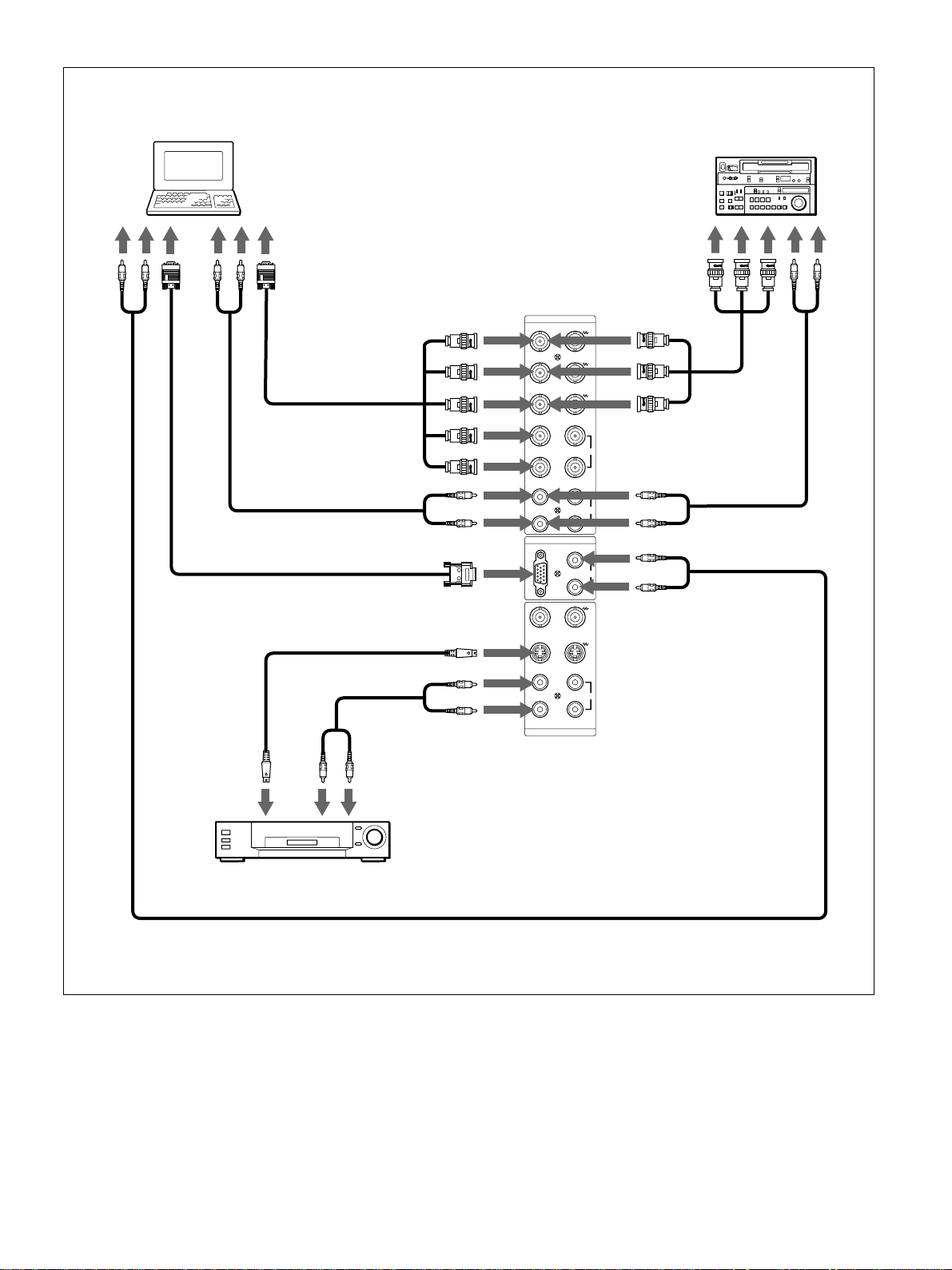
Anschließen des Monitors
an
Audioausgang
Computer
an
Videoausgang
an
Audioausgang
an
Videoausgang
* an R(R-Y)/G(Y)/
B(B-Y), HD/COMP,
VD IN
an AUDIO IN
an RGB IN
an Y/C oder
VIDEO IN
RGB 1
IN OUT
R-Y
B-Y
HD/
COMP
VD
RGB 2
RGB IN
VIDEO
Y/C
Betacam-SPVideorecorder
an
FarbdifferenzSignalausgang
R
an
Audioausgang
G
Y
B
* an R(R-Y)/G(Y)/
SYNC
B(B-Y) IN
an AUDIO IN
L
AUDIO
R
L
AUDIO IN
R
an AUDIO IN
an AUDIO IN
an Videoausgang
an Audioausgang
Videorecorder, Laser-DiscPlayer, Spielekonsole usw.
* Diese Anschlüsse können nicht gleichzeitig benutzt werden.
L
R
IN OUT
LINE
AUDIO
15 (DE)
Page 76
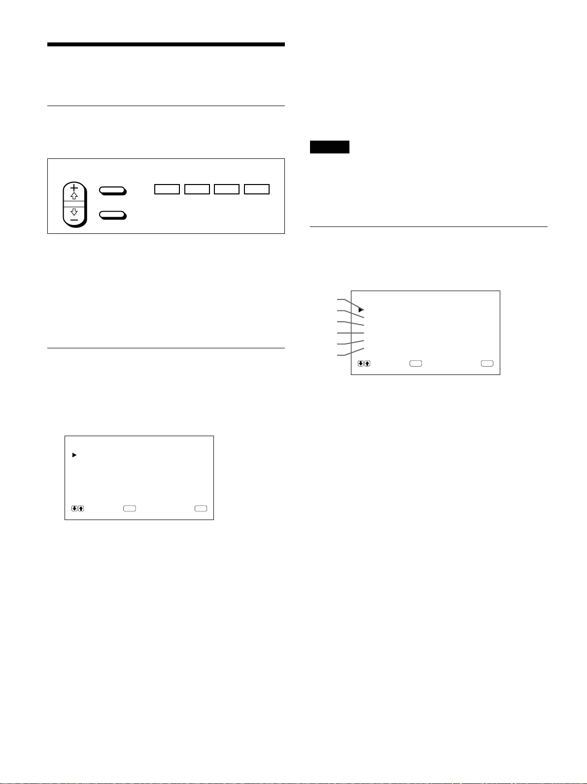
Die Bildschirmmenüs
Die Bildschirmmenüs
Arbeiten mit den Menüs
Menütasten
Zur Arbeit mit den Menüs stehen am Monitor und auf
der Fernbedienung vier Menütasten zur Verfügung.
Fernbedienung Monitor
SELECT
In dieser Bedienungsanleitung werden zum
Beschreiben der Verfahren die Tasten auf dem
Bedienfeld verwendet.
Die Taste ENTER auf der Fernbedienung hat dieselbe
Funktion wie die Taste ENT auf dem Bedienfeld, und
die Tasten SELECT +M/–m auf der Fernbedienung
entsprechen den Tasten M/m auf dem Bedienfeld.
Menükonfiguration
Erläuterungen zum Auswählen der Menüsprache
finden Sie auf Seite 26(DE).
1 Drücken Sie MENU.
Das Hauptmenü erscheint auf dem Bildschirm.
MENU
ENTER
MENU ENT
m
M
Soll wieder die normale Bildschirmanzeige zu sehen
sein, drücken Sie die Taste MENU so oft, bis das
Menü ausgeblendet wird.
Übersicht über die Menüs
Hinweis
Wenn eine Funktion nicht zur Verfügung steht,
erscheint “_ _ _ _” neben der entsprechenden Option.
Welche Funktionen zur Verfügung stehen, hängt vom
Typ des Eingangssignals ab.
Menü BILDEINST
Auf dem Menü BILDEINST können Sie die
Bildqualität einstellen.
1
2
3
4
5
6
1 KONTRAST
Mit M verstärken Sie den Kontrast, mit m schwächen
Sie ihn ab.
BILDEINST
KONTRAST : 80
HEL L I GKE I T : 00
FARBE : 00
PHASE : 00
FARBTEMP :HOCH
ZURÜCKSETZEN
WÄH L EN ABBRUCH
ENTER
MENU
HAUPTMENÜ
BILDEINST
BI LDGRÖSSE
KONF IG
SPEICHERN
FERNBED
STATUS
WÄHL EN ABBRUCH
ENTER
MENU
2 Mit den Tasten M/m können Sie den Cursor (B)
bewegen und mit der Taste ENT ein Menü
auswählen.
Das ausgewählte Menü erscheint auf dem
Bildschirm.
3 Mit den Tasten M/m können Sie den Cursor (B)
bewegen und mit der Taste ENT eine Option
auswählen.
Das Menü zu der ausgewählten Option erscheint
auf dem Bildschirm.
4 Mit M/m können Sie eine Einstellung ändern oder
auswählen, mit ENT können Sie diese Einstellung
bestätigen.
Die entsprechende Einstellung wird gespeichert,
und es erscheint wieder das vorhergehende Menü.
2 HELLIGKEIT
Mit M stellen Sie das Bild heller, mit m dunkler ein.
3 FARBE
Mit M verstärken Sie die Farbsättigung, mit m
schwächen Sie sie ab.
4 PHASE
Mit M verstärken Sie den Grünanteil im Bild, mit m
den Rotanteil.
5 FARBTEMP
Wählen Sie als Farbtemperatur HOCH oder TIEF aus.
6 ZURÜCKSETZEN
Mit dieser Option können Sie die Optionen 1 bis 5
im Menü BILDEINST auf die werkseitigen Werte
zurücksetzen.
Erläuterungen zum Zurücksetzen finden Sie unter
“Zurücksetzen der Optionen im Menü BILDEINST auf die
ursprünglichen Werte” auf Seite 22(DE).
16 (DE)
Page 77

Die Bildschirmmenüs
Menü BILDGRÖSSE
Mit diesem Menü können Sie das Bild positionieren
und seine Größe verändern.
7
8
9
q;
qa
qs
7 H GRÖSSE
Zum Einstellen der Bildbreite. Mit M stellen Sie das
Bild breiter, mit m schmaler ein.
8 H LAGE
Zum Einstellen der horizontalen Zentrierung. Mit M
verschieben Sie das Bild nach rechts, mit m nach
links.
9 V GRÖSSE
Zum Einstellen der Bildhöhe. Mit M stellen Sie das
Bild höher, mit m niedriger ein.
BI LDGRÖSSE
H GRÖSSE : 00
HLAGE : 00
V GRÖSSE : 0 0
VLAGE : 00
BILDFORMAT : 4x3
ZURÜCKSETZEN
WÄH L EN ABBRUCH
ENTER
MENU
Um dieses Problem zu vermeiden, setzen Sie die
Werte für H/V GRÖSSE und H/V LAGE auf die
werkseitigen Einstellungen zurück. Bei Problemen mit
den werkseitigen Einstellungen setzen Sie die
Einstellungen auf die unten angegebenen Werte.
Erläuterungen zum Einstellen finden Sie unter
“Zurücksetzen von Bildgröße und -position auf die
ursprünglichen Werte” (Seite 24 (DE)).
•DTV-Signale für werkseitige Einstellungen:
1080/60i, 480/60i, 575/50i, 480/60p
•Andere DTV-Signale und die empfohlenen
Einstellungen:
H V H V BILD-
GRÖSSE GRÖSSE
1080/50i + 48 + 11 + 10 – 02 16:9
1080/48i MAX + 09 + 12 – 02 16:9
1152/50i + 33 – 02 + 20 0 16:9
LAGE LAGE FORMAT
Menü KONFIG
Dieses Menü dient zum Einstellen des Signals und zur
Auswahl der Menüsprache.
q; V LAGE
Zum Einstellen der vertikalen Zentrierung. Mit M
verschieben Sie das Bild nach oben, mit m nach
unten.
qa BILDFORMAT
Zum Einstellen des Bildseitenverhältnisses auf 4:3
oder 16:9.
qs ZURÜCKSETZEN
Mit dieser Option können Sie die Optionen 7 bis qa
im Menü BILDGRÖSSE auf die werkseitigen Werte
zurücksetzen.
Erläuterungen zum Zurücksetzen finden Sie unter
“Zurücksetzen von Bildgröße und -position auf die
ursprünglichen Werte” auf Seite 24(DE).
Hinweis
Wenn das Gerät DTV-Signale empfängt und die
Einstellung von H/V GRÖSSE oder H/V LAGE im
Menü BILDGRÖSSE geändert wird, wechselt das
System in den Abtastverschiebungsmodus. In diesem
Fall ist das Bild unter Umständen verschwommen,
oder horizontale Linien sind zu sehen, denn in diesem
Modus ist die Phase beim Schreiben in den Speicher
schneller als die Phase beim Lesen aus dem Speicher.
Dabei handelt es sich nicht um eine Fehlfunktion des
Systems.
qd
qf
qg
qh
KONF IG
ANHEBUNG : HOCH
H F ILTER :AUTO
BILDMENUE : EIN
SPRACHE
WÄHL EN ABBRUCH
ENTER
MENU
qd ANHEBUNG (Schärfe)
Sie können den Korrekturpegel für die Konturen
ändern:
TIFF: Standardeinstellung für VIDEO-Signal
HOCH: Standardeinstellung für Computersignal
qf H FILTER
Im Normalfall sollte AUTO eingestellt sein.
Wählen Sie HOCH, wenn es auf dem Bildschirm zu
einer Bildverdoppelung kommt.
Wählen Sie TIEF, wenn Moiré-Muster oder
Störrauschen auftreten. Das Moiré-Muster oder das
Störrauschen wird verringert, auch wenn das Bild
dann nicht ganz scharf ist.
qg BILDMENUE
Wählen Sie EIN, so werden beim Einschalten oder
nach einem Wechsel des Eingangssignals etwa fünf
Sekunden lang oben am Monitorbildschirm
Informationen zum Eingangssignal angezeigt.
17 (DE)
Page 78

Die Bildschirmmenüs
qh SPRACHE
Sie können für die Menüanzeigen eine von fünf
Sprachen wählen.
Die folgenden Sprachen stehen zur Verfügung:
Englisch, Deutsch, Französisch, Italienisch und
Spanisch.
Erläuterungen zum Einstellen der Sprache finden Sie unter
“Auswählen der Menüsprache” auf Seite 26(DE).
Menü SPEICHERN
Dieses Menü dient zum Speichern und
Wiederaufrufen der Einstellungen in den Menüs
BILDEINST, BILDGRÖSSE und KONFIG (nur die
Optionen ANHEBUNG und H FILTER).
SPEICHERN
qj
qk
LADEN
SPEICHERN
WÄHL EN ABBRUCH
ENTER
MENU
Erläuterungen dazu finden Sie unter “Der Speicher” auf
Seite 25(DE).
qj LADEN
Ruft die voreingestellten Werte auf.
qk SPEICHERN
Speichert die Einstellungen.
Menü FERNBED
Dieses Menü dient zum Einstellen des
Fernbedienungsmodus.
w; FERNBED ART
Dient zum Auswählen des Fernbedienungsmodus.
TV: Für Monitore oder Fernsehgeräte von Sony
PROJ: Für Projektoren von Sony
AUS: Deaktiviert die Fernbedienung.
Näheres dazu finden Sie unter “Verwenden einer anderen
Fernbedienung” auf Seite 28(DE).
wa NUR FERNBED
Wählen Sie EIN, um die Tasten am Bedienfeld vorn
am Monitor zu deaktivieren. Der Monitor läßt sich
jetzt nur noch über die Fernbedienung steuern. Wenn
NUR FERNBED auf EIN gesetzt ist, leuchten die
Anzeigen an der Vorderseite des Monitors nicht.
Wenn Sie die Tasten am Bedienfeld vorn wieder
aktivieren wollen, setzen Sie NUR FERNBED mit der
Fernbedienung auf AUS, oder drücken Sie die Taste
CTRL, während Sie den Schalter 1 gedrückt halten.
Der Monitor wechselt in den Bereitschaftsmodus und
kann wieder über die Tasten am Bedienfeld vorn
gesteuert werden.
Diese Einstellung bleibt erhalten, wenn Sie das
Netzkabel lösen, gilt jedoch nicht mehr, wenn Sie den
Monitor am Hauptnetzschalter ausschalten.
Menü STATUS
Dieses Menü dient zum Anzeigen von Informationen
zum Status des Monitors.
ws
wd
wf
wg
wh
wj
STATUS
[ PFM-510A1WE ]
SERIEN Nr. : 2000001
BETRIEBSTD :000000H
SOFTWARE :
TEMPERATUR : OK
LÜFTER : OK
Ver
1.00
ql
w;
wa
FERNBED
INDEXNUMMER : 001
FERNBED ART : TV
NUR FERNBED : AUS
WÄH L EN ABBRUCH
ENTER
MENU
ql INDEXNUMMER
Dient zum Einstellen der Indexnummer für den
Monitor.
Hinweis
Verwenden Sie zum Einstellen der Nummer die
Tasten am Monitor.
Näheres zum Einstellen der Indexnummer finden Sie unter
“Steuern eines bestimmten Monitors über die
Fernbedienung” auf Seite 27(DE).
18 (DE)
ws Modellname
Hier wird der Modellname angegeben.
wd SERIEN Nr.
Hier wird die Seriennummer angegeben.
wf BETRIEBSTD
Gibt die Gesamtzahl der Betriebsstunden des
Monitors an.
Hinweis
Der Bereitschaftsmodus zählt nicht zur Betriebsdauer.
wg SOFTWARE
Gibt die Version der Systemsoftware an.
Page 79

Die Bildschirmmenüs
wh TEMPERATUR
Gibt an, ob die interne Temperatur des Monitors im
Normalbereich liegt.
OK: Normal
NEGATIV: Nicht im Normalbereich
Wenn die interne Temperatur nicht im Normalbereich
liegt, wird NEGATIV angezeigt, und die Option
blinkt rot. Die Anzeige 1 auf dem Bedienfeld blinkt
ebenfalls.
Hinweis
Die Meldung “TEMPERATUR NEGATIV” erscheint
möglicherweise, wenn die Lüftungsöffnungen
blockiert sind oder der Monitor an einem Ort mit
ungenügender Luftzufuhr aufgestellt ist. Sorgen Sie in
diesem Fall dafür, daß die Lüftungsöffnungen nicht
blockiert werden, und stellen Sie den Monitor an
einem Ort mit ausreichender Luftzufuhr auf. Wird die
Meldung dann immer noch angezeigt, wenden Sie
sich bitte an Ihren autorisierten Sony-Händler.
Wenn die Anzeige 1 blinkt oder NEGATIV angezeigt wird,
schlagen Sie unter “Selbstdiagnosefunktion” auf Seite
26(DE) nach.
wj LÜFTER
Dieser Monitor enthält Ventilatoren. Hier wird
angegeben, ob die Ventilatoren ordnungsgemäß
funktionieren.
OK: Normal
NEGATIV: Nicht normal
Wenn die Ventilatoren nicht ordnungsgemäß
funktionieren, wird NEGATIV angezeigt, und die
Option blinkt rot. Die Anzeige 1 auf dem Bedienfeld
blinkt ebenfalls.
Hinweis
Wenn die Meldung “LÜFTER NEGATIV” erscheint,
wenden Sie sich bitte an Ihren autorisierten SonyHändler.
Wenn die Anzeige 1 blinkt oder NEGATIV angezeigt wird,
schlagen Sie unter “Selbstdiagnosefunktion” auf Seite
26(DE) nach.
Ventilatoren
Lüftungsöffnungen
Hinweis
Die Ventilatoren oben messen die interne Temperatur
des Monitors und steuern die
Rotationsgeschwindigkeit der Ventilatoren. Wenn die
Umgebungstemperatur hoch ist, erhöht sich die
Drehzahl der Ventilatoren, und das Summen der
Ventilatoren wird lauter.
19 (DE)
Page 80

Die Anzeigefunktionen
Die Anzeigefunktionen
Vorbereitungen
•Schalten Sie den Monitor ein.
•Schalten Sie die angeschlossenen Geräte ein, und
starten Sie die Wiedergabe einer Videoquelle.
•Wenn beim Einschalten des Monitors oder bei einem
Wechsel des Eingangssignals Informationen zum
Eingangssignal angezeigt werden sollen, setzen Sie
“BILDMENUE” im Menü KONFIG auf EIN.
•Erläuterungen zum Auswählen der
Bildschirmmenüsprache finden Sie auf Seite 26(DE).
Auswählen des Bildes
1 Drücken Sie die Taste CTRL am Bedienfeld des
Monitors.
Die Tasten RGB1, YUV, RGB2, LINE und Y/C
leuchten auf.
Hinweis
Es empfiehlt sich, als Eingangssignalquelle ein
Videogerät mit TBC-Funktion (Time Base Corrector)
zu verwenden. Wenn ein Signal ohne TBC eingespeist
wird, wird aufgrund einer Störung des
Synchronisationssignals unter Umständen kein Bild
angezeigt.
Anzeige von Eingangssignal und Monitorstatus
Informationen zum Eingangssignal und zum
Monitorstatus erscheinen beim Einschalten des Geräts
oder bei einem Wechsel des Eingangssignals etwa 5
Sekunden lang auf dem Bildschirm.
Wollen Sie diese Funktion ausschalten, gehen Sie
bitte wie im folgenden beschrieben vor.
2 Wählen Sie mit den folgenden Tasten das
gewünschte Eingangssignal aus.
RGB1:Das über die RGB1-Anschlüsse
eingespeiste Audio- und Videosignal wird
ausgewählt, sofern es sich bei diesem
Eingangssignal um ein RGB-Signal
handelt.
YUV: Das über die RGB1-Anschlüsse
eingespeiste Audio- und Videosignal wird
ausgewählt, sofern es sich bei diesem
Eingangssignal um ein Farbdifferenzsignal
handelt.
RGB2:Das über die RGB2-Anschlüsse
eingespeiste Audio- und Videosignal wird
ausgewählt.
LINE: Das über den Anschluß VIDEO IN und die
Buchse AUDIO IN (LINE-Anschlüsse)
eingespeiste Audio- und Videosignal wird
ausgewählt.
Y/C: Das über den Anschluß Y/C IN und die
Buchse AUDIO IN (LINE-Anschlüsse)
eingespeiste Audio- und Videosignal wird
ausgewählt.
1 Drücken Sie MENU.
Das Hauptmenü erscheint auf dem Bildschirm.
HAUPTMENÜ
BILDEINST
BI LDGRÖSSE
KONF IG
SPEICHERN
FERNBED
STATUS
WÄH L EN ABBRUCH
ENTER
MENU
2 Stellen Sie den Cursor (B) mit den Tasten M/m
auf “KONFIG”, und drücken Sie ENT.
Das Menü KONFIG erscheint auf dem
Bildschirm.
KONF IG
ANHEBUNG : HOCH
H F ILTER :AUTO
BILDMENUE : EIN
SPRACHE
WÄHL EN ABBRUCH
ENTER
MENU
Farbsystem oder Horizontal-/Vertikalfrequenz
Signaltyp
PAL
LINE·Y/C
Das ausgewählte Eingangssignal (Bild) erscheint
auf dem Bildschirm.
Sie können das Eingangssignal auch mit der
Fernbedienung auswählen.
20 (DE)
3 Stellen Sie den Cursor (B) mit den Tasten M/m
auf “BILDMENUE”, und drücken Sie ENT.
Das folgende Menü erscheint auf dem Bildschirm.
BILDMENUE : EIN
Page 81

Die Anzeigefunktionen
4 Setzen Sie “BILDMENUE” mit der Taste M auf
AUS, und drücken Sie ENT.
Die BILDMENUE-Funktion ist damit deaktiviert.
Wollen Sie diese Funktion wieder aktivieren, setzen
Sie in Schritt 4 oben die Option “BILDMENUE” auf
EIN.
Hinweis
Unabhängig von der Einstellung oben können Sie die
Informationen zum Eingangssignal jederzeit abrufen,
indem Sie die Taste DISPLAY auf der Fernbedienung
drücken.
Die Informationsliste zum Eingangssignal
Farbsystem oder Horizontal-/Vertikalfrequenz
31.5
kHz
/60
Signaltyp
Eingangssignal Anzeige von Farbsystem oder
NTSC NTSC
PAL PAL
VGAa) (Grafik) 31,5 kHz 60 Hz
VGA (Text) 31,5 kHz 70 Hz
HDTV 33,8 kHz 60 Hz
Macb) 13 Zoll 35,0 kHz 67 Hz
VESAc) 800×600 37,9 kHz 60 Hz
VESA 1024×768 48,4 kHz 60 Hz
Mac 16 Zoll 49,7 kHz 75 Hz
ATId) 1280×1024 64,0 kHz 60 Hz
Mac 21 Zoll 68,7 kHz 75 Hz
VESA 1280×1024 80,0 kHz 75 Hz
RGB1 ·RGB
Horizontal-/Vertikalfrequenz
Hz
Anzeigen zum Monitorstatus auf dem
Bildschirm
Bildschirmanzeige Bedeutung
31.5kHz / 60Hz Bei dem ausgewählten
(Beispiel) Eingangssignal handelt es sich um
ein Computersignal im RGB-Format.
525 / 60 (Beispiel) Bei dem ausgewählten
Eingangssignal handelt es sich um
ein RGB- oder Farbdifferenzsignal.
NTSC Bei dem ausgewählten
Eingangssignal handelt es sich um
ein NTSC-Signal.
PAL Bei dem ausgewählten
Eingangssignal handelt es sich um
ein PAL-Signal.
ANDERE Das Eingangssignal liegt außerhalb
des Fangbereichs.
NO SYNC Es ist kein Eingangssignal
vorhanden.
STUMM Der Ton ist stummgeschaltet.
RGB1 RGB Für RGB1 gilt der Signalmodus
RGB.
RGB1 YUV Für RGB1 gilt als Signalmodus das
Farbdifferenzsignal.
LINE COMP Für LINE wurde als Eingangssignal
das FBAS-Signal ausgewählt.
LINE Y/C Für LINE wurde als Eingangssignal
das Y/C-Signal ausgewählt.
a) VGA ist ein eingetragenes Warenzeichen der
International Business Machines Corporation, USA.
b) Mac (Macintosh) ist ein eingetragenes Warenzeichen der
Apple Computer, Inc.
c) VESA ist ein eingetragenes Warenzeichen der Video
Electronics Standard Association.
d) ATI ist ein eingetragenes Warenzeichen der ATI
Technologies, Inc.
Hinweis
Wenn ein HDTV-Signal eingeht, speisen Sie das
dreistufige Synchronisationssignal über den Anschluß
G/Y IN ein.
21 (DE)
Page 82

Einstellen der Bildqualität
Einstellen der Bildqualität
Sie können das Bild anzeigen lassen und dabei
Kontrast, Helligkeit, Chroma (Farbintensität) und
Phase einstellen. Diese Werte können Sie für die
einzelnen Eingangssignale unabhängig voneinander
einstellen. Darüber hinaus können Sie die
eingestellten Werte im Gerät speichern.
PHASE
Wählen Sie mit den Tasten M/m die Option “PHASE”
aus, und drücken Sie ENT.
Stellen Sie mit den Tasten M/m für die Phase einen
Wert zwischen -50 (Minimum) und +50 (Maximum)
ein.
M: Der Grünanteil im Bild wird verstärkt.h
m: Der Rotanteil im Bild wird verstärkt.
Einstellen von Kontrast, Helligkeit, Farbe und Phase
Drücken Sie MENU, so daß das Hauptmenü auf dem
Bildschirm angezeigt wird, und wählen Sie auf dem
Menü BILDEINST mit den Tasten M/m die Option
“KONTRAST”, “HELLIGKEIT”, “FARBE” oder
“PHASE”.
KONTRAST
Wählen Sie mit den Tasten M/m die Option
“KONTRAST” aus, und drücken Sie ENT.
Stellen Sie mit den Tasten M/m für den Kontrast einen
Wert zwischen 0 (Minimum) und 100 (Maximum)
ein.
M: Der Kontrast wird verstärkt.
m: Der Kontrast wird abgeschwächt.
HELLIGKEIT
Wählen Sie mit den Tasten M/m die Option
“HELLIGKEIT” aus, und drücken Sie ENT.
Stellen Sie mit den Tasten M/m für die Helligkeit
einen Wert zwischen –50 (Minimum) und +50
(Maximum) ein.
M: Der Grünanteil im Bild wird verstärkt.
m: Der Rotanteil im Bild wird verstärkt.
Hinweise
•Für ein RGB-Signal können Sie FARBE und
PHASE nicht einstellen.
•Für ein Farbdifferenzsignal können Sie PHASE nicht
einstellen.
•Für ein PAL-Signal können Sie PHASE nicht
einstellen.
•Ändern Sie den Pegel von FARBE/PHASE (nur
NTSC) nicht, wenn es sich bei dem ausgewählten
Signal nicht um ein NTSC- oder PAL-Signal
handelt.
Eine solche Änderung hätte zwar auf das gerade
angezeigte Bild keine Auswirkungen, würde aber bei
einem später eingespeisten NTSC- oder PAL-Signal
zu Bildstörungen führen.
Zurücksetzen der Optionen im
Menü BILDEINST auf die
ursprünglichen W erte
1 Stellen Sie im Menü BILDEINST den Cursor (B)
mit den Tasten M/m auf “ZURÜCKSETZEN”,
und drücken Sie ENT.
Das folgende Menü erscheint auf dem Bildschirm.
ZURÜCKSETZEN : NEIN
FARBE
Wählen Sie mit den Tasten M/m die Option “FARBE”
aus, und drücken Sie ENT.
Stellen Sie mit den Tasten M/m für die Farbintensität
einen Wert zwischen –50 (Minimum) und +50
(Maximum) ein.
M: Die Farbintensität wird verstärkt.
m: Die Farbintensität wird abgeschwächt.
22 (DE)
WÄH L EN ABBRUCH
ENTER
2 Drücken Sie M/m.
“NEIN” wird zu “JA”.
ZURÜCKSETZEN : JA
WÄH L EN ABBRUCH
ENTER
MENU
MENU
Page 83

Einstellen der Bildqualität / Einstellen von Bildgröße und Bildposition
3 Drücken Sie ENT.
Die Optionen im Menü BILDEINST werden auf
die ursprünglichen Werte zurückgesetzt.
Um das Zurücksetzen abzubrechen, drücken Sie die
Taste MENU, bevor Sie die Taste ENT drücken.
Einstellen von Bildgröße
und Bildposition
Sie können das Bild verschieben, so daß es auf den
Bildschirm paßt, bzw. Bildhöhe und Bildbreite
unabhängig voneinander einstellen.
Einstellen der Bildgröße
1 Drücken Sie MENU.
Das Hauptmenü erscheint auf dem Bildschirm.
4 Ändern Sie mit M/m die Größe des Bildes.
M: Das Bild wird breiter.
m: Das Bild wird schmaler.
Die Bildbreite wird auf dem Monitorbildschirm
als ein Wert zwischen –50 (Minimum) und +50
(Maximum) angezeigt. Die werkseitige
Einstellung ist 00.
5 Drücken Sie ENT.
Nun erscheint wieder das Menü BILDGRÖSSE.
6 Stellen Sie den Cursor (B) mit den Tasten M/m
auf “V GRÖSSE”, und drücken Sie ENT.
Das folgende Menü erscheint auf dem Bildschirm.
V GRÖSSE : 00
HAUPTMENÜ
BILDEINST
BI LDGRÖSSE
KONF IG
SPEICHERN
FERNBED
STATUS
WÄH L EN ABBRUCH
ENTER
MENU
2 Stellen Sie den Cursor (B) mit den Tasten M/m
auf “BILDGRÖSSE”, und drücken Sie ENT.
Das Menü BILDGRÖSSE erscheint auf dem
Bildschirm.
BI LDGRÖSSE
H GRÖSSE : 0 0
HLAGE : 00
V GRÖSSE : 00
VLAGE : 00
BILDFORMAT : 4x3
ZURÜCKSETZEN
WÄHL EN ABBRUCH
ENTER
MENU
3 Stellen Sie den Cursor (B) mit den Tasten M/m
auf “H GRÖSSE”, und drücken Sie ENT.
Das folgende Menü erscheint auf dem Bildschirm.
7 Ändern Sie mit M/m die Größe des Bildes.
M: Das Bild wird höher.
m: Das Bild wird niedriger.
Die Bildbreite wird auf dem Monitorbildschirm
als ein Wert zwischen –50 (Minimum) und +50
(Maximum) angezeigt. Die werkseitige
Einstellung ist 00.
8 Drücken Sie ENT.
Nun erscheint wieder das Menü BILDGRÖSSE.
Einstellen der Bildposition
1 Stellen Sie im Menü BILDGRÖSSE den Cursor
(B) mit den Tasten M/m auf “H LAGE”, und
drücken Sie ENT.
Das folgende Menü erscheint auf dem Bildschirm.
HLAGE : 00
H GRÖSSE : 00
23 (DE)
Page 84
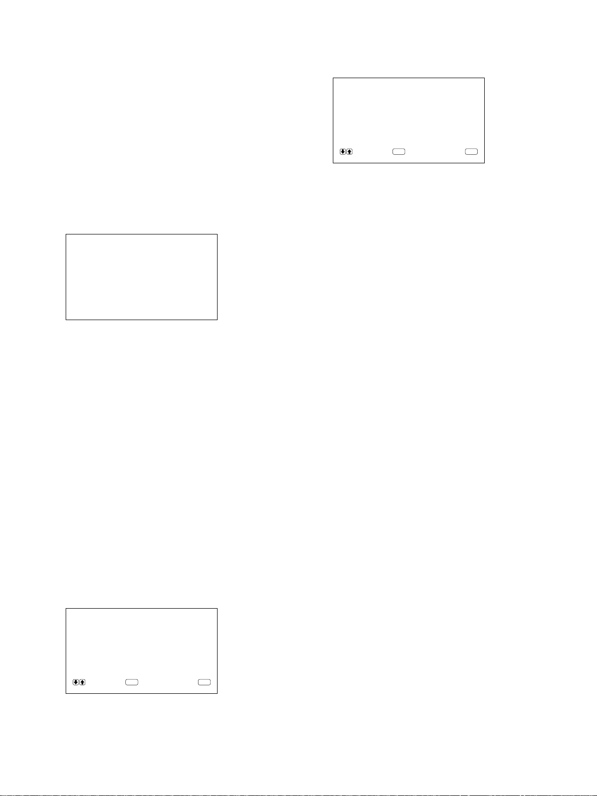
Einstellen von Bildgröße und Bildposition
2 Ändern Sie mit M/m die Position des Bildes.
M: Das Bild verschiebt sich nach rechts.
m: Das Bild verschiebt sich nach links.
Die horizontale Lage des Bildes wird auf dem
Monitorbildschirm als ein Wert zwischen –50
(Minimum) und +50 (Maximum) angezeigt. Die
werkseitige Einstellung ist 00.
3 Drücken Sie ENT.
Nun erscheint wieder das Menü BILDGRÖSSE.
4 Stellen Sie den Cursor (B) mit den Tasten M/m
auf “V LAGE”, und drücken Sie ENT.
Das folgende Menü erscheint auf dem Bildschirm.
VLAGE : 00
2 Drücken Sie M/m.
“NEIN” wird zu “JA”.
ZURÜCKSETZEN : JA
WÄHL EN ABBRUCH
ENTER
MENU
3 Drücken Sie ENT.
Nun gelten wieder die ursprüngliche Bildgröße
und -position.
Um das Zurücksetzen abzubrechen, drücken Sie die
Taste MENU, bevor Sie die Taste ENT drücken.
5 Ändern Sie mit M/m die Position des Bildes.
M: Das Bild verschiebt sich nach oben.
m: Das Bild verschiebt sich nach unten.
Die vertikale Lage des Bildes wird auf dem
Monitorbildschirm als ein Wert zwischen –50
(Minimum) und +50 (Maximum) angezeigt. Die
werkseitige Einstellung ist 00.
6 Drücken Sie ENT.
Nun erscheint wieder das Menü BILDGRÖSSE.
Zurücksetzen von Bildgröße und position auf die ursprünglichen
Werte
1 Stellen Sie im Menü BILDGRÖSSE den Cursor
(B) mit den Tasten M/m auf
“ZURÜCKSETZEN”, und drücken Sie ENT.
Das folgende Menü erscheint auf dem Bildschirm.
ZURÜCKSETZEN : NEIN
24 (DE)
WÄHL EN ABBRUCH
ENTER
MENU
Page 85

Der Speicher
Der Speicher
Mit der Funktion SPEICHERN können Sie die
aktuelle Bildeinstellung für die einzelnen
Eingangssignale speichern.
Die gespeicherten Einstellungen können Sie danach
jederzeit abrufen.
Die Optionen in den Menüs BILDEINST,
BILDGRÖSSE und KONFIG (nur die Optionen
ANHEBUNG und H FILTER) können gespeichert
werden.
Auf diese Weise können Sie die Bildeinstellungen für
bis zu 5 Eingangssignale speichern.
Speichern der aktuellen Einstellungen
1 Drücken Sie MENU.
Das Hauptmenü erscheint auf dem Bildschirm.
HAUPTMENÜ
BILDEINST
BI LDGRÖSSE
KONF IG
SPEICHERN
FERNBED
STATUS
WÄHL EN ABBRUCH
ENTER
2 Stellen Sie den Cursor (B) mit den Tasten M/m
auf “SPEICHERN”, und drücken Sie ENT.
Das Menü SPEICHERN erscheint auf dem
Bildschirm.
SPEICHERN
LADEN
SPEICHERN
MENU
4 Stellen Sie den Cursor (B) mit den Tasten M/m
auf SPEI 1 bis 5, und drücken Sie ENT.
Daraufhin wird fünf Sekunden lang “BEENDET”
angezeigt.
Die aktuellen Einstellungen werden unter der
ausgewählten Speichernummer im Gerät
gespeichert.
Wenn unter der ausgewählten Speichernummer
bereits Daten gespeichert sind, werden in der
rechten Spalte neben der Speichernummer der
Signaltyp und das Farbsystem bzw. die
Horizontal-/Vertikalfrequenz angezeigt.
Signaltyp
Farbsystem oder Horizontal-/Vertikalfrequenz
SPEICHERN
SPEI1:RGB 31.5k
SPEI2:LEER
SPEI3:LEER
SPEI4:LEER
SPEI5:LEER
WÄH L EN ABBRUCH
ENTER
Hz
60
Hz
MENU
Aufrufen der gespeicherten Einstellungen
1 Stellen Sie im Menü SPEICHERN den Cursor (B)
mit den Tasten M/m auf “LADEN”, und drücken
Sie ENT.
Das folgende Menü erscheint auf dem Bildschirm.
LADEN
SPEI1:RGB 31.5k
SPEI 2 : LEER
SPEI 3 : LEER
SPEI 4 : LEER
SPEI 5 : LEER
Hz
60
Hz
WÄHL EN ABBRUCH
ENTER
MENU
3 Stellen Sie den Cursor (B) mit den Tasten M/m
auf “SPEICHERN”, und drücken Sie ENT.
Das folgende Menü erscheint auf dem Bildschirm.
SPEICHERN
SPEI 1 : LEER
SPEI 2 : LEER
SPEI 3 : LEER
SPEI 4 : LEER
SPEI 5 : LEER
WÄH L EN ABBRUCH
ENTER
MENU
WÄH L EN ABBRUCH
ENTER
MENU
2 Stellen Sie den Cursor (B) mit den Tasten M/m
auf SPEI 1 bis 5, und drücken Sie ENT.
Daraufhin wird fünf Sekunden lang “BEENDET”
angezeigt.
Das Bild wird nun so eingestellt, wie im
ausgewählten Speicher definiert.
Hinweise
•Die Speichereinstellungen können nicht abgerufen
werden, wenn das ausgewählte Signal nicht dem
voreingestellten Signal entspricht.
•Die folgenden Optionen können Sie speichern:
25 (DE)
Page 86

Der Speicher / Auswählen der Menüsprache / Selbstdiagnosefunktion
Menü BILDEINST
– KONTRAST
– HELLIGKEIT
– FARBE
– PHASE
– FARBTEMP
– BILDVERST
Menü BILDGRÖSSE
– H GRÖSSE
– H LAGE
– V GRÖSSE
– V LAGE
– BILDFORMAT
Menü KONFIG
– ANHEBUNG
– H FILTER
Auswählen der
Menüsprache
3 Stellen Sie den Cursor (B) mit den Tasten M/m
auf “SPRACHE”, und drücken Sie ENT.
Das folgende Menü erscheint auf dem Bildschirm.
SPRACHE
ENGL I SH
DEUTSCH
FRANÇA I S
ITALIANO
ESPAÑOL
WÄHL EN ABBRUCH
ENTER
MENU
4 tellen Sie den Cursor (B) mit den Tasten M/m auf
die gewünschte Sprache, und drücken Sie ENT.
Nun erscheinen die Bildschirmmenüs in der
ausgewählten Sprache.
ENGLISH: English
DEUTSCH: Deutsch
FRANÇAIS: Französisch
ITALIANO: Italienisch
ESPAÑOL: Spanisch
5 Drücken Sie MENU.
Nun erscheint wieder das Menü KONFIG.
Sie können für die Menüanzeigen eine von fünf
Sprachen wählen.
Die folgenden Sprachen stehen zur Verfügung:
Englisch, Deutsch, Französisch, Italienisch und
Spanisch.
1 Drücken Sie MENU.
Das Hauptmenü erscheint auf dem Bildschirm.
HAUPTMENÜ
BILDEINST
BI LDGRÖSSE
KONF IG
SPEICHERN
FERNBED
STATUS
WÄHL EN ABBRUCH
ENTER
MENU
2 Stellen Sie den Cursor (B) mit den Tasten M/m
auf “KONFIG”, und drücken Sie ENT.
Das Menü KONFIG erscheint auf dem
Bildschirm.
KONF IG
ANHEBUNG : HOCH
H F ILTER : AUTO
BILDMENUE : EIN
SPRACHE
WÄH L EN ABBRUCH
ENTER
MENU
Selbstdiagnosefunktion
Das Gerät verfügt über eine Selbstdiagnosefunktion.
Damit wird der Zustand des Monitors anhand der
blinkenden Anzeige 1 und der Zahlen in der Anzeige
SERVICE CODE angezeigt. Die Zahlen geben
Auskunft über den aktuellen Zustand des Monitors.
Wenn das Gerät ordnungsgemäß arbeitet, blinkt nur
der Punkt rechts unten in der Anzeige SERVICE
CODE.
Wenn die Anzeige 1 blinkt, überprüfen Sie die
Nummer und wenden sich an Ihren autorisierten
Sony-Händler.
1 Überprüfen Sie die zweistellige Nummer in der
Anzeige SERVICE CODE.
In der Anzeige erscheint eine Nummer, oder
mehrere Nummern werden alle halbe Sekunde
abwechselnd angezeigt.
2 Ziehen Sie den Netzstecker des Geräts aus der
Netzsteckdose.
Teilen Sie die Nummer Ihrem autorisierten SonyHändler mit.
26 (DE)
Page 87

Steuern eines
ON
ID MODE
SET
OFF
bestimmten Monitors
über die Fernbedienung
Mit der mitgelieferten Fernbedienung können Sie
einen bestimmten Monitor steuern, ohne die anderen
angeschlossenen Monitore zu beeinflussen.
1 Drücken Sie die Taste ID MODE ON auf der
Fernbedienung.
Die Indexnummern der Monitore werden auf allen
Monitoren weiß angezeigt. (Jedem Monitor ist
werkseitig eine eigene Indexnummer zwischen 1
und 255 zugeordnet.)
Unter “So ändern Sie die Indexnummer” in der Spalte
rechts auf dieser Seite erfahren Sie, wie Sie die
Indexnummer ändern können.
Indexnummer
Steuern eines bestimmten Monitors über die Fernbedienung
4 Drücken Sie nach dem Einstellen die Taste ID
MODE OFF.
Der Monitor schaltet wieder in den normalen
Modus.
ON
SET
OFF
ID MODE
So ändern Sie die Indexnummer
Sie können die Indexnummer gegebenenfalls ändern.
Verwenden Sie zum Ändern der Nummer die Tasten
am Monitor.
1 Drücken Sie MENU.
Das Hauptmenü erscheint auf dem Bildschirm.
ON
SET
OFF
ID MODE
INDEXNUMMER 117 . . .
2 Geben Sie mit den Tasten 0 – 9 auf der
Fernbedienung die Indexnummer des Monitors
ein, den Sie steuern wollen.
Die eingegebene Nummer erscheint rechts neben
der Indexnummer der Monitore.
Eingegebene Nummer
INDEXNUMMER 117 117
10/0
2
1
4
7
3
5
6
8
9
3 Drücken Sie ID MODE SET.
Die Zeichen auf dem ausgewählten Monitor
werden nun blau angezeigt, die auf den anderen
Monitoren rot.
HAUPTMENÜ
BILDEINST
BI LDGRÖSSE
KONF IG
SPEICHERN
FERNBED
STATUS
WÄH L EN ABBRUCH
ENTER
MENU
2 Stellen Sie den Cursor (B) mit den Tasten M/m
auf “FERNBED”, und drücken Sie ENT.
Das Menü FERNBED erscheint auf dem
Bildschirm.
FERNBED
INDEXNUMMER : 001
FERNBED ART : TV
NUR FERNBED : AUS
WÄHL EN ABBRUCH
ENTER
MENU
3 Stellen Sie den Cursor (B) mit den Tasten M/m
auf “INDEXNUMMER”, und drücken Sie ENT.
Das folgende Menü erscheint auf dem Bildschirm.
INDEXNUMMER : 001
Sie können nun einen bestimmten Monitor
steuern. (Im ID-Modus stehen alle Funktionen
außer POWER ON/OFF zur Verfügung.)
4 Stellen Sie die Indexnummer mit M/m ein, und
drücken Sie ENT.
Nun erscheint wieder das Menü FERNBED.
27 (DE)
Page 88

Verwenden einer anderen Fernbedienung
Verwenden einer
anderen Fernbedienung
Folgende Operationen lassen sich steuern.
•Ein- und Ausschalten
•Eingangswahl
•Menüfunktionen
•Bildeinstellungen: Kontrast, Phase und Farbe
•Ein- und Ausblenden der Bildschirmanzeigen (nur
bei Videomonitoren und Fernsehgeräten)
Je nach Modell Ihrer Fernbedienung stehen nur
bestimmte Tasten zur Verfügung, und Sie können nur
bestimmte Operationen ausführen. Eine Übersicht
finden Sie in der Tabelle unten.
Modell der Fernbedienung RM-854 RM-1271 RM-PJ1292 RM-PJ1000
Einstellung der Option FERNBED ART
Eingangswahl RGB1 RGB A A A
RGB2 — B B B
LINE LINE1 VIDEO VIDEO VIDEO
Menütasten MENU MENU PAGE oder < PAGE oder < MENU oder <
ENTER ENTER ,,ENTER oder ,
++MMM
––mmm
Bildeinstellung Kontrast CONTRAST+/– CONTR+/– CONTR+/– CONTR+/–
Farbe CHROMA+/– COLOR+/– COLOR+/– COLOR+/–
Phase PHASE+/– HUE+/– HUE+/– HUE+/–
Bildschirminformationen DISPLAY — STATUS ON STATUS ON
TV PJ PJ PJ
28 (DE)
Page 89

Technische Daten
Bildverarbeitung
Fangbereich Horizontaler Wert: 15,6 bis
80 kHz
Vertikaler Wert: 48 bis 120 Hz
Voreingestelltes Signal
Eingang: 12 Formate (siehe Seite
21(DE))
Videospeicher 1.152 × 1.152 × 24 Bit (RGB
gesamt)
Abtastrate 14,3 bis 50 MHz max.
Phasenverschiebung (entspricht
100-MHz-Abtastung)
Bildschirmsystem
Plasmabildschirmn
(Wechselstrom)
Anzeigeauflösung
1024 Punkte × 1024 Zeilen
Pixeldichte 0,90 (horizontal) × 0,51 (vertikal)
mm
Bildgröße 921 (horizontal) × 522 (vertikal)
mm
Bildschirmgröße 42 Zoll, Diagonale 1.058 mm
Eingänge und Ausgänge
RGB1
R (R-Y)/ G (Y)/B (B-Y) IN
BNC-Anschlüsse (×3)
0,714 Vp-p/nicht
zusammengesetzt, 75 Ohm
(automatischer Abschluß)
1 Vp-p/zusammengesetzt, 75 Ohm
(automatischer Abschluß)
SYNC IN(HD/COMP, VD)
BNC-Anschlüsse (×2)
Horizontales (oder
zusammengesetztes)
Synchronisationssignal,
vertikales
Synchronisationssignal, 1 bis
5 Vp-p, hohe Impedanz
AUDIO IN (L, R) Cinchbuchsen (×2)
500 mV effektiver Mittelwert,
hohe Impedanz
R (R-Y)/ G (Y)/B (B-Y) OUT
BNC-Durchschleifanschlüsse (×3)
Technische Daten
SYNC OUT (HD/COMP, VD)
BNC-Durchschleifanschlüsse (×2)
Horizontales (oder
zusammengesetztes)
Synchronisationssignal,
vertikales
Synchronisationssignal
AUDIO OUT (L, R)
Cinch-Durchschleifanschlüsse (×2)
RGB2
RGB IN D-Sub, 15polig
Siehe “Stiftbelegung” auf Seite
30(DE).
AUDIO IN (L, R) Cinchbuchsen (×2)
500 mV effektiver Mittelwert,
hohe Impedanz
LINE (NTSC, PAL)
VIDEO IN BNC-Anschluß (×1)
FBAS-Videosignal, 1 Vp-p ±2 dB,
sync-negativ, 75 Ohm
(automatischer Abschluß)
Y/C IN Mini-DIN, 4polig (×1)
Y-Signal (Luminanz): 1 Vp-p
±2 dB, sync-negativ, 75 Ohm
(automatischer Abschluß)
C-Signal (Chrominanz): Burst
0,286 Vp-p ±2 dB (NTSC),
75 Ohm (automatischer
Abschluß) Burst 0,3 Vp-p ±2 dB
(PAL), 75 Ohm (automatischer
Abschluß)
AUDIO IN (L, R) Cinchbuchsen (×2)
500 mV effektiver Mittelwert,
hohe Impedanz
VIDEO OUT BNC-Durchschleifanschluß (×1)
Y/C OUT Mini-DIN, 4polig (×1),
Durchschleifanschluß
AUDIO OUT (L, R) (variable Ausgänge)
Cinch-Durchschleifanschlüsse (×2)
MONITOR OUT AUDIO (L, R)
Cinchbuchsen (×2)
max. 500 mV effektiver
Mittelwert, hohe Impedanz
CONTROL S (IN, OUT)
Stereominibuchsen (×2)
5 Vp-p
REMOTE (RS-232C)
Mini-DIN, 8polig (×1)
29 (DE)
Page 90

Technische Daten
SPEAKERS 6 bis 16 Ohm, 7 W + 7 W (bei
Impedanz von 8 Ohm)
Allgemeines
Betriebsspannung 100 bis 120 V Wechselstrom,
50/60 Hz, 4,7 A/410 W
220 bis 240 V Wechselstrom,
50/60 Hz, 2,2 A/400 W
Betriebsbedingungen
Temperatur: 0 °C bis 35 °C
Luftfeuchtigkeit: 20 bis 90 %
(nicht kondensierend)
Atmosphärischer Druck: 700 bis
1060 hPa
Lager-/Transportbedingungen
Temperatur: –10 °C bis +40 °C
Luftfeuchtigkeit: 20 bis 90 %
(nicht kondensierend)
Atmosphärischer Druck: 700 bis
1060 hPa
×
Abmessungen 1036
Gewicht 45 kg
636 × 152 mm (B/H/T)
Stiftbelegung
Y/C-Buchse (Mini-DIN, 4polig)
Chrominanz
Masse
Anschluß RGB IN (15poliger, D-SubAnschluß)
Stift Nr. Signal
1 Videosignal Rot oder R-Y
2 Videosignal Grün oder Y
Luminanz
Masse
Mitgeliefertes Zubehör
Netzkabel (1)
Netzsteckerhalter (1)
Fernbedienung RM-921 (1)
R6-Batterien der Größe AA (2)
Ferritkerne (2)
Halterung für Fußstützen (2)
Schrauben für Halterungen für
Fußstützen (6)
Stabilisatoren für Monitor (2)
Bedienungsanleitung (1)
Änderungen, die dem technischen Fortschritt dienen,
bleiben vorbehalten.
3 Videosignal Blau oder B-Y
4 Masse
5 Masse
6 Masse Rot
7 Masse Grün
8 Masse Blau
9 Nicht belegt
10 Masse
11 Masse
12 SDA
13 Horizontales oder zusammengesetztes
Synchronisationssignal
14 Vertikales Synchronisationssignal
15 SCL
30 (DE)
Page 91

31 (DE)
Page 92

ADVERTENCIA
Para evitar el peligro de incendio o descargas
eléctricas, no exponga la unidad a la lluvia ni
a la humedad.
Presencia de alta tensión peligrosa en el
interior de la unidad. No abra el aparato.
Solicite asistencia técnica sólo a personal
especializado.
Para los clientes de Europa
Éste es un producto de clase A. En un ambiente doméstico,
este producto puede causar interferencias radioeléctricas,
en cuyo caso el usuario puede tener que tomar las medidas
adecuadas.
Para los usuarios del modelo
PFM-510A1WE
ESTE APARATO DEBE CONECTARSE A TIERRA
IMPORTANTE
Los conductores de este cable de alimentación están
coloreados de acuerdo con el código siguiente:
Verde-y-amarillo : Masa
Azul
Marron
Puesto que los colores de los conductores del cable de
alimentación de este aparato no pueden corresponder al
código de color que identifica los terminales de su enchufe,
proceda de la forma siguiente:
El conductor de colores verde-y-amarillo deberá conectarse
al terminal del enchufe marcado con la letra E o simbolo de
puesta a masa I, para seguridad o de colores verde o
verde-y-amarillo.
El conductor de color azul deberá conectarse al terminal
marcado con la letra N o de color negro.
El conductor de color marron deberá conectarse al terminal
marcado con la letra L o de color rojo.
: Neutro
: Activo
Nota
Al conectar un ordenador a este monitor, instale los
núcleos de ferrita suministrados. En caso contrario,
el monitor no cumplirá las normas FCC/IC/CE
(EN55022) obligatorias.
Instalación de los núcleos de ferrita
Fije los núcleos de ferrita en ambos extremos del
cable de alimentación de CA. Cierre firmemente la
tapa hasta que las abrazaderas chasqueen.
o bien
Abrazaderas
La toma mural debe estar instalada cerca del equipo y
debe accederse a ésta con facilidad.
2 (ES)
Page 93

Índice
Precauciones .............................................................4 (ES)
Características...........................................................5 (ES)
Ubicación y función de componentes y
controles................................................................ 6 (ES)
Parte frontal / Laterales............................................. 6 (ES)
Panel de control ........................................................ 7 (ES)
Panel de conectores derecho ..................................... 8 (ES)
Panel de conectores izquierdo................................. 10 (ES)
Mando a distancia RM-921..................................... 10 (ES)
Instalación................................................................ 12 (ES)
Uso de los pies replegables ..................................... 12 (ES)
Precaución............................................................... 13 (ES)
Conexiones .............................................................. 14 (ES)
Conexión del cable de alimentación de CA............ 14 (ES)
Ejemplo de conexión .............................................. 14 (ES)
Uso de los menús en pantalla ................................ 16 (ES)
Empleo mediante menús ......................................... 16 (ES)
Menú guía ............................................................... 16 (ES)
Visualización de la imagen ..................................... 20 (ES)
Conmutación de la imagen ..................................... 20 (ES)
Visualización de información sobre la señal de
entrada y el estado del monitor .......................... 20 (ES)
Ajuste de la imagen.................................................22 (ES)
Ajuste del contraste, brillo, crominancia y fase...... 22 (ES)
Restauración de los valores originales del menú
CONTROL IMAG............................................. 22 (ES)
Cambio del tamaño y posición de la imagen........23 (ES)
Cambio del tamaño de la imagen............................ 23 (ES)
Ajuste de la posición de la imagen ......................... 23 (ES)
Restauración del tamaño y posición originales de
la imagen............................................................ 24 (ES)
Uso de la memoria................................................... 25 (ES)
Almacenamiento de la condición actual ................. 25 (ES)
Restablecimiento de la condición almacenada ....... 25 (ES)
Selección del idioma en pantalla ........................... 26 (ES)
Función de autodiagnóstico................................... 26 (ES)
Empleo de un monitor específico con el mando a
distancia .............................................................. 27 (ES)
Uso del otro mando a distancia .............................28 (ES)
Especificaciones ..................................................... 29 (ES)
ES
Español
3 (ES)
Page 94

Precauciones
Precauciones
Seguridad
•Emplee la unidad con 100 a 120 V CA o 220 a 240
V CA.
•La placa de características que indica la tensión de
funcionamiento, consumo de energía, etc., está
situada en la parte posterior de la unidad.
•Si se introduce algún objeto sólido o líquido en la
unidad, desenchúfela y haga que sea examinado por
personal cualificado antes de volver a utilizarla.
•Desenchufe la unidad de la toma mural si no va a
utilizarla durante varios días o más.
•Para desconectar el cable de alimentación de CA, tire
del enchufe. No tire nunca del propio cable.
•Para instalar la unidad en el suelo, asegúrese de
utilizar los pies replegables.
Instalación
•Con el fin de evitar el recalentamiento interno de la
unidad, permita que reciba una ventilación adecuada.
No la coloque sobre superficies (alfombras, mantas,
etc.) ni cerca de materiales (cortinas, tapices) que
puedan bloquear los orificios de ventilación.
•No instale la unidad en un lugar cerca de fuentes de
calor como radiadores o salidas de aire caliente, ni
en lugares expuestos a la luz solar directa, polvo
excesivo o vibraciones o golpes mecánicos.
•Al instalar múltiples equipos con la unidad, pueden
producirse problemas como un funcionamiento
defectuoso del mando a distancia, ruido de imagen o
sonido, etc., según la posición de la unidad y de los
demás equipos.
Embalaje
Conserve la caja y los materiales de embalaje, ya que
son ideales para transportar la unidad. Al trasladar la
unidad, embálela tal como se indica en la caja.
Si desea realizar alguna consulta referente a la unidad,
póngase en contacto con un proveedor Sony
autorizado.
PDP (panel de visualización de plasma)
•Es posible que aparezcan pequeños puntos negros y/
o brillantes en el PDP. Esto es normal.
•No muestre la misma imagen fija en la pantalla
durante mucho tiempo consecutivo. En caso
contrario, puede aparecer una imagen residual en
parte de un panel. Utilice el protector de pantalla
para igualar la visualización en pantalla.
Limpieza
Para mantener la unidad como nueva, límpiela
periódicamente con una solución detergente poco
concentrada. Nunca utilice disolventes fuertes como
diluyentes o bencina ni limpiadores abrasivos, ya que
pueden dañar el acabado. Como precaución de
seguridad, desenchufe la unidad antes de limpiarla.
4 (ES)
Page 95

Características
Las unidades de la serie PFM-510A1W son monitores
de 16:9 de panel plano de 42 pulgadas. Éstos están
equipados con el panel PDP (Plasma Display Panel) y
aceptan distintos tipos de señales mediante el
convertidor de exploración incorporado.
Calidad de imagen mejorada
El PDP logra una mayor calidad de imagen con 1024
× 1024 líneas. Así se producen imágenes HDTV y PC
muy detalladas.
Podrá obtener mejor brillo y contraste con respecto a
los monitores convencionales.
Convertidor de exploración interno de alto
rendimiento
El monitor dispone de un convertidor de exploración
de alto rendimiento. Mediante el empleo de un
algoritmo único, el monitor procesa las señales con
una amplia gama de formatos (vídeo, HDTV, PC,
etc.).
Flexibilidad
Se proporciona una ranura de opción para las
expansiones futuras.
El adaptador de ranura de opción permite actualizar el
sistema de forma rápida y fácil.
Características
Otras características
•Tres grupos de entradas de vídeo con entradas de
audio: una de vídeo compuesta o entradas Y/C, una
entrada RVB y una entrada RVB/componente.
•Muestra la señal HDTV con señal de sincronización
de tres niveles.
•Filtro de peine tridimensional para la separación
NTSC Y/C.
•Filtro de peine por correlación de líneas para la
separación PAL Y/C.
•Detección automática de señales de entrada con
indicación.
1)
•Compatibilidad con Windows95/98
PnP (Plug and
Play).
•Función de ganancia automática de imagen: esta
función ajusta y mejora automáticamente el contraste
cuando se introduce una señal de baja intensidad.
•Menú en pantalla para realizar distintos ajustes
•Indicación en pantalla en cinco idiomas para facilitar
el acceso al usuario.
•Ajuste fino del tamaño y posición de la imagen
•Función de memoria para el almacenamiento de
hasta cinco ajustes de imagen.
•Control de ID
•Función de autodiagnóstico.
•Conector REMOTE (RS-232C) (mini DIN de 8
pines)
•Conector Control-S
•Permite emplear mandos a distancia infrarrojos o con
cable utilizando el código SIRCS.
•Ajuste vertical
Advertencia sobre la conexión de alimentación
Utilice un cable de alimentación apropiado para el suministro de alimentación local.
Estados Unidos, Europa Reino Unido, Irlanda, Japón
Canadá continental Australia, Nueva Zelanda
Tipo de enchufe VM0033B COX-07 636 — VM1296
Extremo hembra VM0113 COX-02 VM0310B VM0303B VM1313
Tipo de cable SJT H05VV-F CEE (13) 53º (O.C) HVCTF
Clasificación mínima del 13A/125V 10A/250V 10A/250V 10A/125V
juego de cables
Homologación de seguridad
.........................................................................................................................................................................................................
1) Windows95/98 es una marca comercial registrada de Microsoft Corporation.
UL/CSA VDE VDE DENTORI
5 (ES)
Page 96

Ubicación y función de componentes y controles
Ubicación y función de
componentes y controles
5 Panel de conectores derecho
Para obtener información detallada sobre el panel de
conectores derecho, consulte “Panel de conectores
derecho” en la página 8(ES).
Parte frontal / Laterales
Parte frontal
1
Lateral izquierdo
Lateral derecho
2
6
6 Cubierta del panel derecho
Ábrala para utilizar el panel de conectores derecho.
Para obtener más información sobre cómo abrir la cubierta de
este panel, consulte la parte baja de esta página.
Para abrir la cubierta del panel
Afloje los tornillos en el sentido contrario a las agujas
del reloj y abra la cubierta.
Para retirar la cubierta del panel
Afloje los tornillos tal como se muestra en la siguiente
ilustración y retire la cubierta del panel.
3
4
5
1 Pies replegables
Utilícelos para colocar el monitor en el suelo.
Para obtener más información sobre el uso de los pies
replegables, consulte “Uso de los pies replegables” en la
página 12(ES).
2 Panel de control
Para obtener más información sobre el panel de control,
consulte “Panel de control” en la página 7(ES).
3 Cubierta del panel izquierdo
Ábrala para utilizar el panel de conectores izquierdo.
Es posible instalar el mando a distancia en la parte
posterior de esta cubierta.
Para obtener más información sobre cómo abrir la
cubierta del panel, consulte la columna derecha de esta
página.
Tornillos
Para instalar el mando a distancia en la
cubierta del panel
Instale el mando a distancia en la parte posterior de la
cubierta del panel izquierdo, tal como se ilustra a
continuación.
Mando a
distancia
4 Panel de conectores izquierdo
Para obtener más información sobre el panel de conectores
izquierdo, consulte “Panel de conectores izquierdo” en la
página 10(ES).
6 (ES)
Nota
Al introducir el mando a distancia, asegúrese de
orientar la parte superior hacia arriba y la parte
posterior hacia fuera.
Page 97

Panel de control
Ubicación y función de componentes y controles
VOL – VOL + MENU ENT RGB1 YUV RGB2 LINE Y/C CTRL
qd qs qa 0 98765 4 32 1
mM
1 Detector de control remoto
Recibe el haz del mando a distancia.
2 Interruptor 1 (de espera) / indicador 1 (de
espera)
Pulse este interruptor para encender el monitor.
Púlselo de nuevo para volver al modo de espera.
El indicador 1 (de espera) se ilumina en color rojo en
el modo de espera.
Si parpadea el indicador 1, consulte “Función de
autodiagnóstico” en la página 26(ES).
3 Indicador de encendidor
Se ilumina cuando el monitor está encendido.
4 Botón CTRL (control)
Para utilizar los botones del panel de control, pulse
primero este botón. A continuación, los botones se
iluminan o parpadean para indicar que pueden
emplearse. Púlselo de nuevo para desactivarlos.
1
9 Botón RGB1
Seleccione la señal RVB introducida mediante los
conectores RGB1.
0 Botón ENT (introducir)
Pulse este botón para seleccionar la opción de menú
que desee.
qa Botones M/m
Pulse estos botones para desplazar el cursor (B) hasta
una opción o para ajustar un valor en un menú.
qs Botón MENU
Pulse este botón para que aparezca el menú.
qd Botones VOL (volumen) +/–
Pulse el botón + para aumentar el volumen o el botón
– para reducirlo.
Nota
Los botones (excepto el interruptor 1 (de espera) 2)
del panel de control no funcionan si no se pulsa
primero el botón CTRL.
5 Botón Y/C
Seleccione la señal introducida mediante la toma Y/C
IN de los conectores LINE.
6 Botón LINE
Seleccione la señal introducida desde el conector
VIDEO IN de los conectores LINE.
7 Botón RGB2
Seleccione la señal introducida mediante los
conectores RGB2.
8 Botón YUV
Seleccione la señal de componente introducida
mediante los conectores RGB1.
7 (ES)
Page 98

Ubicación y función de componentes y controles
Panel de conectores derecho
RGB 1
IN OUT
R
R-Y
G
Y
B
B-Y
RGB IN
HD/
COMP
VD
L
R
RGB 2
L
R
4
SYNC
AUDIO
AUDIO IN
1
2
1 Conectores RGB1 IN
R (R-Y)/G (Y)/B (B-Y) IN (BNC-type): Introduzca
la señal RVB o de componente análoga. Conecte
a la señal de salida RVB o de componente (Y/BY/R-Y) de un ordenador o equipo de vídeo.
Esta unidad también acepta la señal componente
HD análoga (Y/P
B/PR). Introduzca la señal PB
mediante el conector B (B-Y) IN y la señal PR
mediante el conector R (R-Y) IN.
HD/COMP IN (tipo BNC): Introduzca la señal de
sincronización H o de sincronización compuesta.
Conecte a la señal de sincronización H o de
sincronización compuesta de un ordenador o
equipo de vídeo.
VD IN (tipo BNC): Introduzca la señal de
sincronización V. Conecte a la salida de señal de
sincronización V de un ordenador o equipo de
vídeo.
La señal de sincronización externa se selecciona
automáticamente. Consulte la tabla de prioridades a
continuación.
VIDEO
3
Y/C
5
L
AUDIO
R
IN OUT
LINE
6
REMOTE
(RS-232C)
Nota
El proceso de potenciación de imagen de señales de
vídeo (NTSC, PAL) sólo funciona para entradas
compuestas (Y/C) o de componente (Y/R-Y/B-Y).
Es posible que la imagen de la entrada RVB aparezca
borrosa. Esto es normal.
Conector
Señales de sincronización
introducidas
HD/COMP IN Sinc H Sinc comp —
VD IN Sinc V — —
G(Y) IN
Señales Sinc Sinc H Sinc comp
Sinc en Verde Sinc en Verde Sinc en Verde
Sinc en Verde
que deben Sinc V
seleccionarse
AUDIO IN (L/R) (tipo fonográfico): Introduzca la
señal de audio. Conecte a la salida de audio de un
ordenador o equipo de vídeo. Conéctelo al canal
L si la señal de audio es monofónica.
2 Conectores RGB2 IN
RGB IN (D-sub de 15-pines): Conéctelo a la salida
de señal RVB de un ordenador.
AUDIO IN (L/R) (tipo fonográfico): Introduzca la
señal de audio. Conecte a la salida de audio de un
ordenador. Conéctelo al canal L si la señal de
audio es monofónica.
3 Conectores LINE IN
VIDEO IN (tipo BNC): Conéctelo a la salida de
señal de vídeo compuesta del equipo de vídeo.
Y/C IN (Mini DIN de 4 pines): Conéctelo a la
salida de señal Y/C del equipo de vídeo.
AUDIO IN (L/R) (tipo fonográfico): Conéctelo a la
salida de audio del equipo de vídeo. Conéctelo al
canal L si la señal de audio es monofónica.
8 (ES)
Page 99

Ubicación y función de componentes y controles
4 Conectores RGB1 OUT
Estos conectores se utilizan como salidas derivadas de
los conectores RGB1 IN 1.
Cuando el enchufe se conecta a los conectores RGB
OUT, se libera la terminación de 75 ohmios de los
conectores RGB IN, y la señal introducida mediante
los conectores RGB IN se emite a través de estos
conectores.
R (R-Y)/G (Y)/B (B-Y) OUT (tipo BNC): Salidas
derivadas de los conectores RGB IN. Conéctelo a
la salida de señal RVB o de señal componente (Y/
B-Y/R-Y) de otro monitor.
HD/COMP OUT (tipo BNC): Salida derivada del
conector HD/COMP IN. Conéctelo a la entrada
de señal de sincronización H o de sincronización
compuesta de otro monitor.
VD OUT (tipo BNC): Salida derivada del conector
VD IN. Conecte a la entrada de señal de
sincronización V de otro monitor.
Nota
Los conectores HD/COMP OUT y VD OUT son
salidas de alta impedancia.
Al utilizar estas salidas, conecte un monitor con
conector de entrada de sincronización de alta
impedancia; en caso contrario, la imagen puede
oscilar o desaparecer porque no coincide el nivel de
la señal de sincronización.
6 Conector REMOTE (RS-232C) (mini DIN de 8
pines)
Este conector permite realizar el control remoto del
monitor mediante el protocolo RS-232C. Para más
información, consulte con un proveedor Sony
autorizado.
AUDIO OUT (L/R) (tipo fonográfico): Salidas
derivadas de las tomas AUDIO IN. Conéctelo a
las entradas de audio de otro monitor.
5 Conectores LINE OUT
Estos conectores se utilizan como salidas derivadas de
los conectores LINE IN 3.
Cuando el enchufe se conecta al conector VIDEO
OUT o a la toma Y/C OUT, se libera la terminación
de 75 ohmios del conector VIDEO IN o de la toma Y/
C IN, y la señal introducida mediante la toma VIDEO
IN o Y/C IN se emite desde el conector VIDEO OUT
o la toma Y/C OUT.
VIDEO OUT (tipo BNC): Conéctelo a la entrada de
señal de vídeo compuesta de otro monitor o
equipo de vídeo.
Y/C OUT (Mini DIN de 4 pines): Conéctelo a la
entrada de señal Y/C de otro monitor o equipo de
vídeo.
AUDIO OUT (L/R) (tipo fonográfico): Salidas
derivadas de las tomas AUDIO IN. Conéctelo a
las entradas de audio de otro monitor o equipo de
vídeo.
9 (ES)
Page 100

Ubicación y función de componentes y controles
Panel de conectores izquierdo
MONITOR OUT
AUDIO
RL
VARIABLE
CONTROL S
SPEAKERS
(6-16 Ω)
SERVICE CODE
OUT
IN
+
R–
8.8.
1
2
+
L
3
–
4
Notas
•Si conecta la toma CONTROL S IN a la toma
CONTROL S OUT del otro equipo, no podrá
emplear el monitor con el mando a distancia.
•Es posible utilizar el cable de estéreo con
minienchufe en lugar del cable de control S.
3 Terminales SPEAKERS L/R
Conéctelos a altavoces con una impedancia de 6 a 16
ohmios.
Nota
No conecte el cable de altavoz al monitor y a un
amplificador de forma simultánea, ya que una
corriente eléctrica excesiva podría fluir desde el
amplificador y dañar al monitor.
4 Indicador SERVICE CODE
Este indicador es sólo para personal cualificado.
5 Toma -AC IN
Conecte el cable de alimentación de CA a esta toma y
a una toma mural. Una vez conectado el cable de
alimentación de CA, el monitor pasa al modo de
espera.
5
AC IN
1 Tomas MONITOR OUT AUDIO (L/R) (tipo
fonográfico)
Genere la salida de la señal introducida mediante las
tomas AUDIO IN. Conéctelas a las entradas de audio
de un amplificador de audio (no suministrado).
Nota
Estas tomas son salidas variables. Ajuste el volumen
en la posición máxima para definir el nivel de salida
como 500 mVrms.
2 Tomas CONTROL S IN/OUT (minitomas)
Conéctelas a las tomas CONTROL S de los equipos
de vídeo u otros monitores. A continuación, podrá
controlar todos los equipos de forma simultánea con
un solo mando a distancia.
Para controlar los equipos apuntando con el mando a
distancia suministrado al detector de control remoto
del monitor, conecte la toma CONTROL S OUT del
monitor y la toma CONTROL S IN de los demás
equipos.
Mando a distancia RM-921
1
DISPLAY
RGB2
Y/C
2
5
8
ZOOM
SELECT
VOL
POWER
YUV
MTS/MPX
3
6
9
CH
DEGAUSS
MENU
ENTER
CH
2
3
4
5
6
7
8
9
0
qa
MUTING
RGB1
LINE
1
4
7
10/0
STILL
POWER
ON
OFF
ON
SET
OFF
ID MODE
qs
qd
qf
qg
qh
qj
qk
ql»
w;…
wa
10 (ES)
 Loading...