

Sony PFM-50C1,PFM-50C1E Service Manual
.............. ......... ....................
SERVICE MANUAL
.............. ......... ....................
MODEL
DEST. CHASSIS NO. MODEL DEST. CHASSIS NO.
PFM-50C1 WORLD
PFM-50C1E WORLD
FLAT PANEL DISPLAY
SU-P50C WORLD
RM-971 WORLD
PFM-50C1/50C1E FLAT PANEL DISPLAY
SU-P50C FLAT PANEL DISPLAY STAND
RM-971 REMOTE COMMANDER
PFM-50C1/50C1E
! W ARNING
This manual is intended for qualified service personnel only.
To reduce the risk of electric shock, fire or injury, do not perform any servicing other than that
contained in the operating instructions unless you are qualified to do so. Refer all servicing to
qualified service personnel.
! WARNUNG
Die Anleitung ist nur für qualifiziertes Fachpersonal bestimmt.
Alle Wartungsarbeiten dürfen nur von qualifiziertem Fachpersonal ausgeführt werden. Um die
Gefahr eines elektrischen Schlages, Feuergefahr und Verletzungen zu vermeiden, sind bei
Wartungsarbeiten strikt die Angaben in der Anleitung zu befolgen. Andere als die angegeben
Wartungsarbeiten dürfen nur von Personen ausgeführt werden, die eine spezielle Befähigung
dazu besitzen.
! AVERTISSEMENT
Ce manual est destiné uniquement aux personnes compétentes en charge de l’entretien. Afin
de réduire les risques de décharge électrique, d’incendie ou de blessure n’effectuer que les
réparations indiquées dans le mode d’emploi à moins d’être qualifié pour en effectuer d’autres.
Pour toute réparation faire appel à une personne compétente uniquement.
CAUTION
Danger of explosion if battery is incorrectly replaced.
Replace only with the same or equivalent type recommended by the manufacturer.
Dispose of used batteries according to the manufacturer’s instructions.
PFM-50C1/50C1E
CAUTION
Danger of explosion if battery is incorrectly replaced.
Replace only with the same or equivalent type
recommended by the manufacturer.
Dispose of used batteries according to the
manufacturer’s instructions.
Vorsicht!
Explosionsgefahr bei unsachgemäßem Austausch
der Batterie.
Ersatz nur durch denselben oder einen vom
Hersteller empfohlenen ähnlichen Typ. Entsorgung
gebrauchter Batterien nach Angaben des
Herstellers.
ATTENTION
Il y a danger d’explosion s’il y a remplacement
incorrect de la batterie.
Remplacer uniquement avec une batterie du même
type ou d’un type équivalent recommandé par le
constructeur.
Mettre au rebut les batteries usagées conformément
aux instructions du fabricant.
ADVARSEL!
Lithiumbatteri-Eksplosionsfare ved fejlagtig
håndtering.
Udskiftning må kun ske med batteri
af samme fabrikat og type.
Levér det brugte batteri tilbage til leverandøren.
ADVARSEL
Lithiumbatteri - Eksplosjonsfare.
Ved utskifting benyttes kun batteri som
anbefalt av apparatfabrikanten.
Brukt batteri returneres
apparatleverandøren.
VARNING
Explosionsfara vid felaktigt batteribyte.
Använd samma batterityp eller en likvärdig typ
som rekommenderas av apparattillverkaren.
Kassera använt batteri enligt gällande
föreskrifter.
VAROITUS
Paristo voi räjähtää jos se on virheellisesti
asennettu.
Vaihda paristo ainoastaan laitevalmistajan
suosittelemaan tyyppiin.
Hävitä käytetty paristo valmistajan ohjeiden
mukaisesti.
1 (P)
PFM-50C1/50C1E
2 (P)
For the customers in the Netherlands
Voor de klanten in Nederland
Hoe u de batterijen moet verwijderen, leest u in de tekst
van deze handleiding.
Gooi de batterij niet weg maar lever deze in als klein
chemisch afval (KCA).
Für Kunden in Deutschland
Entsorgungshinweis: Bitte werfen Sie nur entladene
Batterien in die Sammelboxen beim Handel oder den
Kommunen. Entladen sind Batterien in der Regel dann,
wenn das Gerät abschaltet und signalisiert “Batterie
leer” oder nach längerer Gebrauchsdauer der Batterien
“nicht mehr einwandfrei funktioniert”. Um
sicherzugehen, kleben Sie die Batteriepole z.B. mit
einem Klebestreifen ab oder geben Sie die Batterien
einzeln in einen Plastikbeutel.
For the customers in the U.S.A. and Canada
RECYCLING LITHIUM-ION BATTERIES
Lithium-Ion batteries are recyclable.
You can help preserve our environment
by returning your used rechargeable
batteries to the collection and recycling
location nearest you.
For more information regarding recycling of rechargeable batteries, call toll free
1-800-822-8837, or visit http://www.rbrc.org/
Caution: Do not handle damaged or leaking Lithium-Ion
batteries.

1
PFM-50C1/50C1E
Table of Contents
1. Service Information
1-1. Board Layout............................................................................................... 1-1
1-2. Disassembly ................................................................................................1-2
1-2-1. QA Board Removal....................................................................1-2
1-2-2. Rear Cover Removal ..................................................................1-3
1-2-3. Q Board Removal.......................................................................1-4
1-2-4. B Board Removal .......................................................................1-5
1-2-5. DC Fan (R) Assy Removal ........................................................ 1-6
1-2-6. AC Inlet Block Assy and SP Board Removal ............................1-7
1-2-7. P Block Assy, S Board, Switching Regulator and DC Fan (B)
Removal .....................................................................................1-8
1-2-8. Bezel Complete Assy Removal..................................................1-9
1-2-9. H1 Board Removal...................................................................1-10
1-2-10. B Block Assy and Panel Assy Removal ..................................1-11
1-2-11. Q/B Bracket Assy Removal ..................................................... 1-12
1-2-12. Plasma Display Panel Removal ...............................................1-13
1-2-13. Common PKG Board Removal................................................ 1-14
1-2-14. Digital PKG Board Removal ...................................................1-15
1-2-15. Collection Joint PKG Board Removal .....................................1-16
1-2-16. Scan PKG Board Removal.......................................................1-17
1-2-17. Scan Joint PKG (A) and (B) Boards Removal.........................1-18
1-2-18. Signal Joint PKG (RU), (MU), (LU) Board Removal .............1-19
1-2-19. Signal Joint PKG (RL), (ML), (LL) Board Removal...............1-20
1-3. Service Position......................................................................................... 1-21
1-3-1. Service Position of Q Board.....................................................1-21
1-3-2. Service Position of B Board .....................................................1-22
1-4. Packaging of the Plasma Display Panel When It Is Shipped to NEC
Corporation ...............................................................................................1-23
1-5. Warning on Power Connection .................................................................1-24
2. Electrical Adjustments
2-1. Equipment Required....................................................................................2-1
2-2. Electrical Adjustments Using the Service Mode ........................................2-1
2-3. White Balance Adjustment .......................................................................2-20
2-4. AD Calibration Adjustment ......................................................................2-20
2-5. Sub Color and Sub Hue Adjustments........................................................2-21
2-6. Video Decoder Adjustment.......................................................................2-21
2-7. Watch Error Adjustment ...........................................................................2-22
2-8. Power Supply Block Adjustment ..............................................................2-22

2
PFM-50C1/50C1E
3. Troubleshooting
3-1. Judging Method When Image Does Not Appear ........................................ 3-1
3-2. Self Diagnosis Function ..............................................................................3-2
3-2-1. Overview ....................................................................................3-2
3-2-2. Abnormality Judgment Criterion ...............................................3-2
4 Semiconductors................................................................................. 4-1
5. Spare Parts
5-1. Notes on Repair Parts..................................................................................5-1
5-2. Exploded Views .......................................................................................... 5-2
5-3. Electrical Parts List ................................................................................... 5-13
6. Block Diagrams
B (1/3), Q (1/2), SP.................................................................................................6-1
B (2/3).....................................................................................................................6-2
B (3/3), Q (2/2), H1, H2, S .....................................................................................6-3
APS-184 (1/2).........................................................................................................6-4
APS-184 (2/2).........................................................................................................6-5
7. Diagrams
7-1. Frame Schematic Diagrams ........................................................................7-2
Frame ........................................................................................................7-2
7-2. Schematic Diagrams and Printed Wiring Boards........................................7-3
Schematic Diagrams
QA.............................................................................................................7-3
Q (1/3) ....................................................................................................... 7-5
Q (2/3) ....................................................................................................... 7-6
Q (3/3) ....................................................................................................... 7-7
B (1/8) .....................................................................................................7-12
B (2/8) .....................................................................................................7-13
B (3/8) .....................................................................................................7-14
B (4/8) .....................................................................................................7-15
B (5/8) .....................................................................................................7-16
B (6/8) .....................................................................................................7-17
B (7/8) .....................................................................................................7-18
B (8/8) .....................................................................................................7-19
H1............................................................................................................ 7-23

3
PFM-50C1/50C1E
H2............................................................................................................ 7-23
S ..............................................................................................................7-24
SP ............................................................................................................7-24
APS-184 (1/4) .........................................................................................7-28
APS-184 (2/4) .........................................................................................7-29
APS-184 (3/4) .........................................................................................7-30
APS-184 (4/4) .........................................................................................7-31
Printed Wiring Boards
QA.............................................................................................................7-3
Q................................................................................................................ 7-8
B .............................................................................................................. 7-10
H1............................................................................................................ 7-23
H2............................................................................................................ 7-23
S ..............................................................................................................7-24
SP ............................................................................................................7-24
APS-184 .................................................................................................. 7-26

1-1
PFM-50C1/50C1E
Section 1
Service Information
1-1. Board Layout
H2
SWITCHING REGULATOR (APS-184)
SP
SCAN JOINT-JOINT PKG
SCAN JOINT PKG (A)
COMMON JOINT
PKG (U)
COMMON JOINT
PKG (L)
SCAN JOINT PKG (B)
SCAN PKG
DIGITAL PKG
COMMON PKG
SIGNAL JOINT PKG (LU)
SIGNAL JOINT PKG (MU)
COLLECTION JOINT PKG
SIGNAL JOINT PKG (RU)
SIGNAL JOINT PKG (ML)
SIGNAL JOINT PKG (LL)
SIGNAL JOINT PKG (RL)
Q
B
S
H1
QA (PFM-50C1)
1-2
PFM-50C1/50C1E
1-2. Disassembly
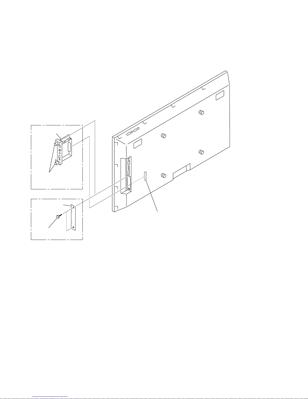
1-2-1. QA Board Removal
CN3009
PFM-50C1E
PFM-50C1
QA board
Blank panel
Two screws
(+PS 3 x 6)
Remove blank panel
[Loosen two panel
stopper screws.]
1-3
PFM-50C1/50C1E
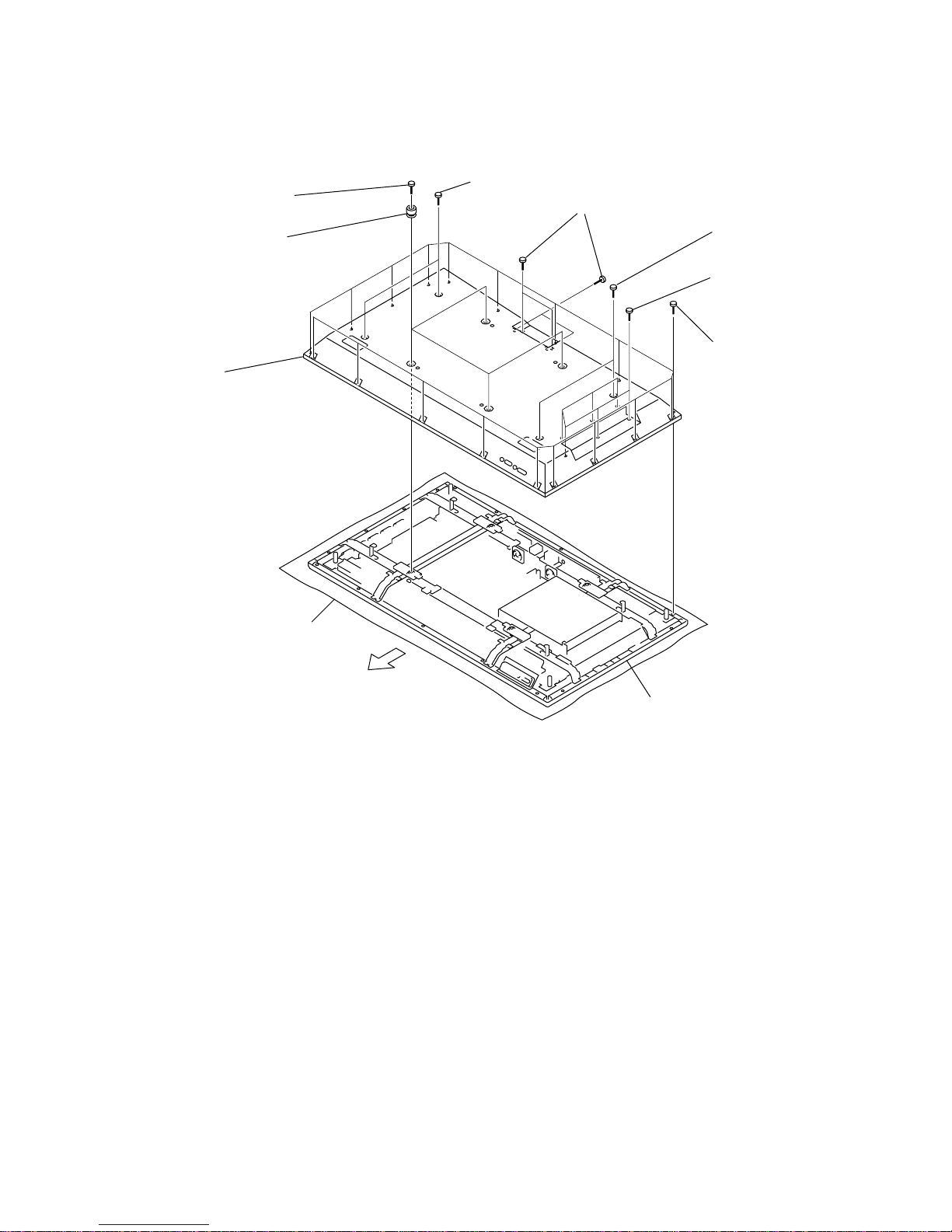
1-2-2. Rear Cover Removal
7
Eighteen
screws
(+BVTP
4 x 16)
8 Rear cover
Conductive cushion
Main chassis
1
Four screws
(+PSW 6 x 20)
6
Four screws
(+PS 3 x 8)
5 Six
screws
(+PS 3 x 8)
3 Two
screws
(+PSW 4 x 8)
4 Two
screws
(+PSW 4 x 8)
2
Four knobs
Top side
1-4
PFM-50C1/50C1E
1 Q/B shield cover
CN3003
CN3011
CN3012
CN3005
CN3007
CN3008
CN3006
CN3001
2 Seven screws
(+PSW 3 x 8)
3 Six hexagon screws
CN3002
4 Q board
Conductive cushion
Main chassis
Top side
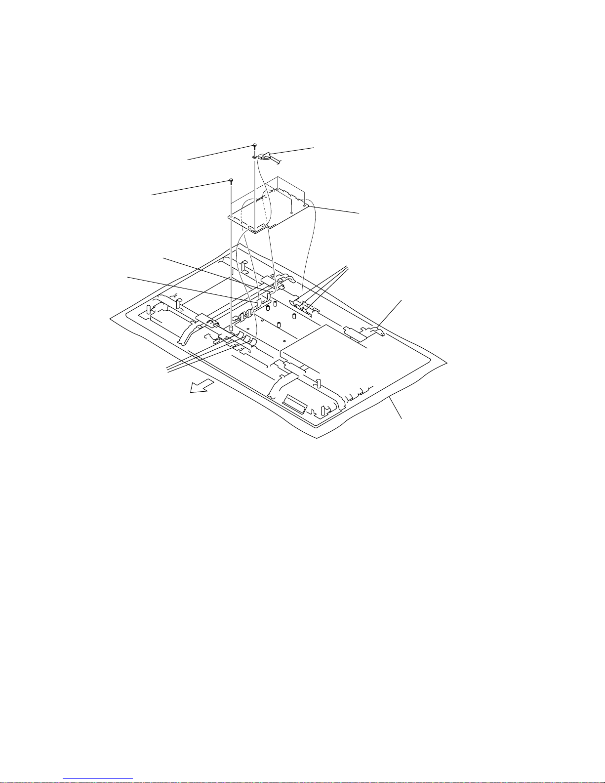
1-2-3. Q Board Removal
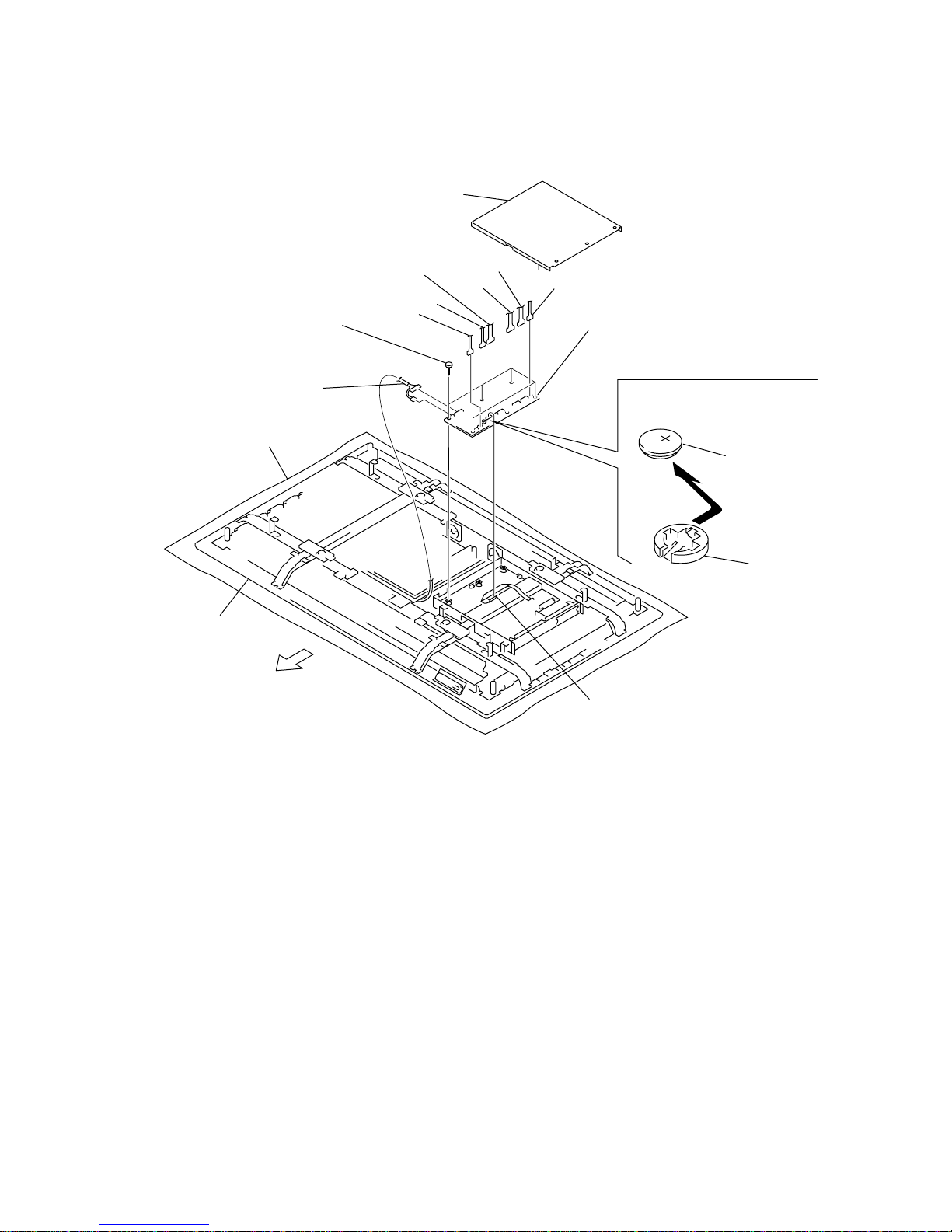
1-5
PFM-50C1/50C1E
CN708
CN1001
CN1005
CN1006
CN101
CN401
CN102
CN1004
2
Six
screws
(+PSW 3 x 8)
3 B board
Conductive cushion
Main chassis
Remove the lithium battery in the
direction of arrow.
Lithium battery
(CR-1220)
Battery holder
Lithium battery removal
1 Q/B shield cover
Top side
1-2-4. B Board Removal

1-6
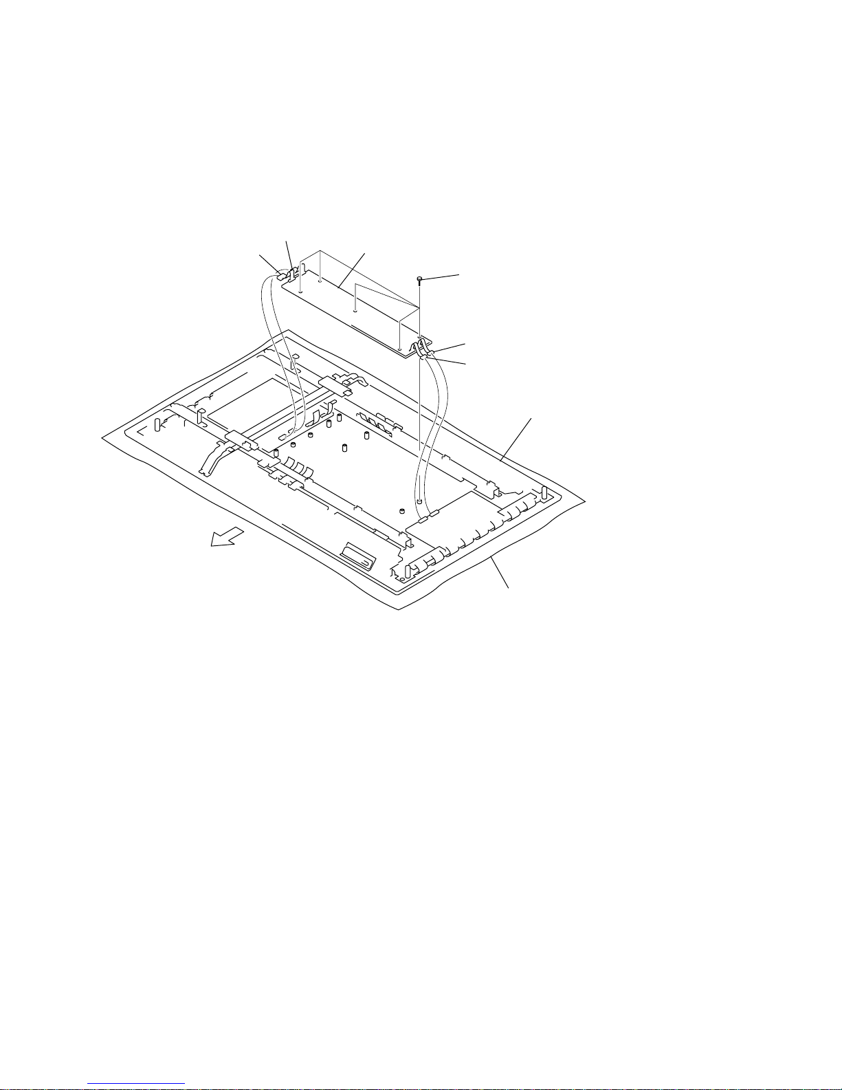
PFM-50C1/50C1E
3 Four screws
(+BVTP 3 x 10)
5 Fan bracket (R)
4
Purse lock
1
Four
screws
(+PSW 4 x 8)
2 DC fan
Conductive cushion
Main chassis
From Q board
Top side
1-2-5. DC Fan (R) Assy Removal
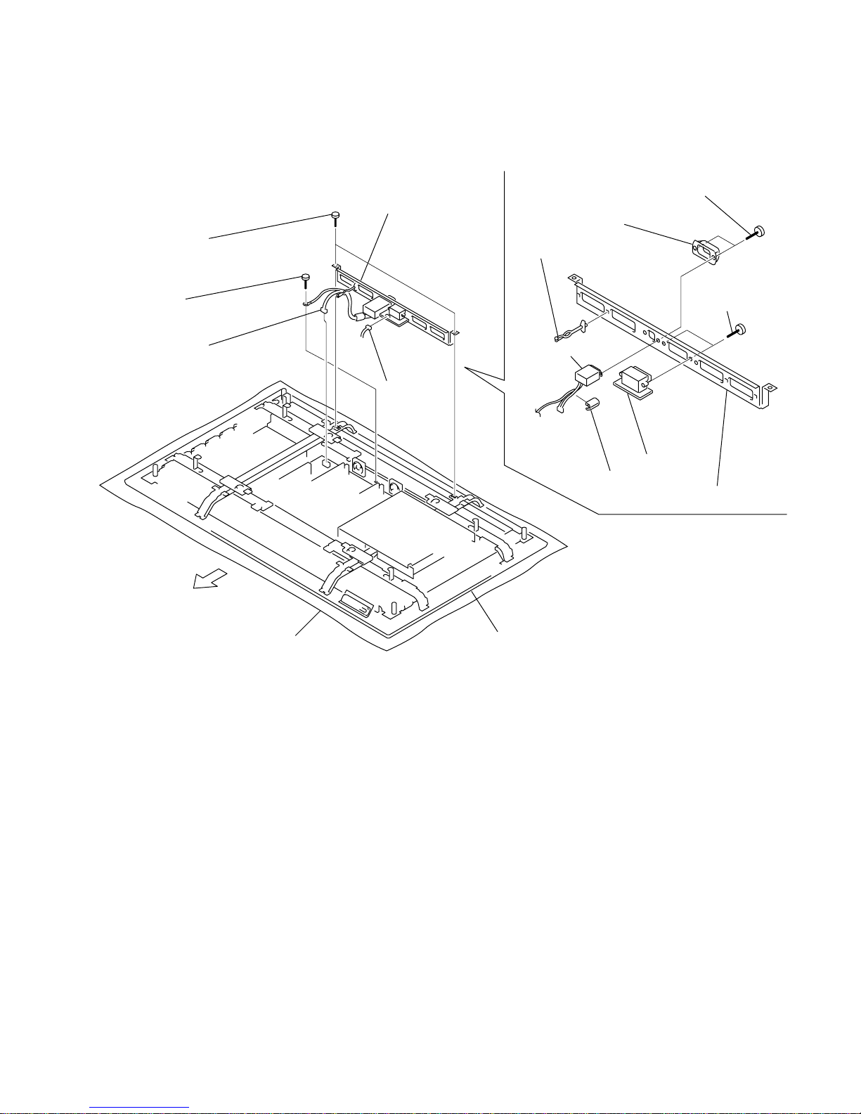
1-7
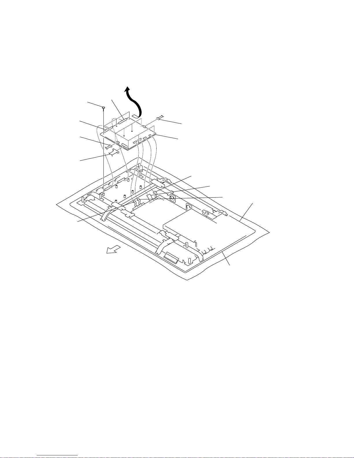
PFM-50C1/50C1E
5 SP board
0 Purse lock
!- Bottom bracket
9
AC inlet
8 Ferrite core
CN9001
CN9001
1
Two
screws
(+PSW 4 x 8)
6
Two
screws
(+PSW 3 x 12)
4
Two
screws
(+BVTP 3 x 10)
7
Plug holder (A
)
3
AC inlet block assy
2 Screw
(+PSW 4 x 8)
Conductive cushion
Main chassis
Top side
1-2-6. AC Inlet Block Assy and SP Board Removal

1-8
PFM-50C1/50C1E
4
Three
screws
(+BVTP 3 x 10)
3
P block assy
5
Three
S boards
CN9003
CN9002
CN1501
CN1501
CN1501
!]
Power bracket
7 Switching regulator
!= Three purse locks
1-9
PFM-50C1/50C1E
Main chassis
Note : When removing the main chassis, be sure that
the two persons or more must work together for removal.
Before starting removal, be sure to remove the operation button assy
from the bezel complete assy. Be very careful not to damage the flexible wires
in the top, bottom, right and left. Place the removed panel on the conductive cushion.
Bezel complete assy
2 Control button
assy
Connector
5 Bezel complete assy
Conductive cushion
Main chassis
Conductive cushion
1
Two screws
(+PSW 4 x 8)
4
Four screws
(+PSW 4 x 8)
3 S
ixteen screws
(+PSW 4 x 8)
6 Two screws
(+PSW 3 x 8)
8 Thrre screws
(+BVTP 2 x 5)
0
H2 board
7 Control button
bracket
9 Control button
CN8651
Top side
1-2-8. Bezel Complete Assy Removal
1-10
PFM-50C1/50C1E
1 Six screws
(+BVTP 4 x 16)
Bezel complete assy
Conductive cushion
2 Filter (V)
holder assy
3 Two screws
(+BVTP 3 x 10)
4 Earth plate
5 H1 board
Top side
1-2-9. H1 Board Removal
1-11
PFM-50C1/50C1E
Two SP boards
Conductive cushion
Main chassis
2
Two
screws
(+PSW 4 x 16)
1
Two
screws
(+PSW 4 x 16)
4 B block assy, Panel assy
3
Two
screws
(+PSW 3 x 16)
CN1501
CN708
Top side
Note : To remove the B block assy and panel assy, remove it after the bezel assembly
has already removed earlier. If not, it can result in distortion of bezel assembly
and damage of optical filter. Before starting removal, be sure to remove the operation button assy
from the bezel complete assy. Be v ery careful not to damage the flexible wires in the top,
bottom, right and left. Place the removed panel on the conductive cushion.
1-2-10.B Block Assy and Panel Assy Removal
n
To remove the B Block Assy and Panel Assy , remove the Bezel block assy, AC inlet block assy beforehand.
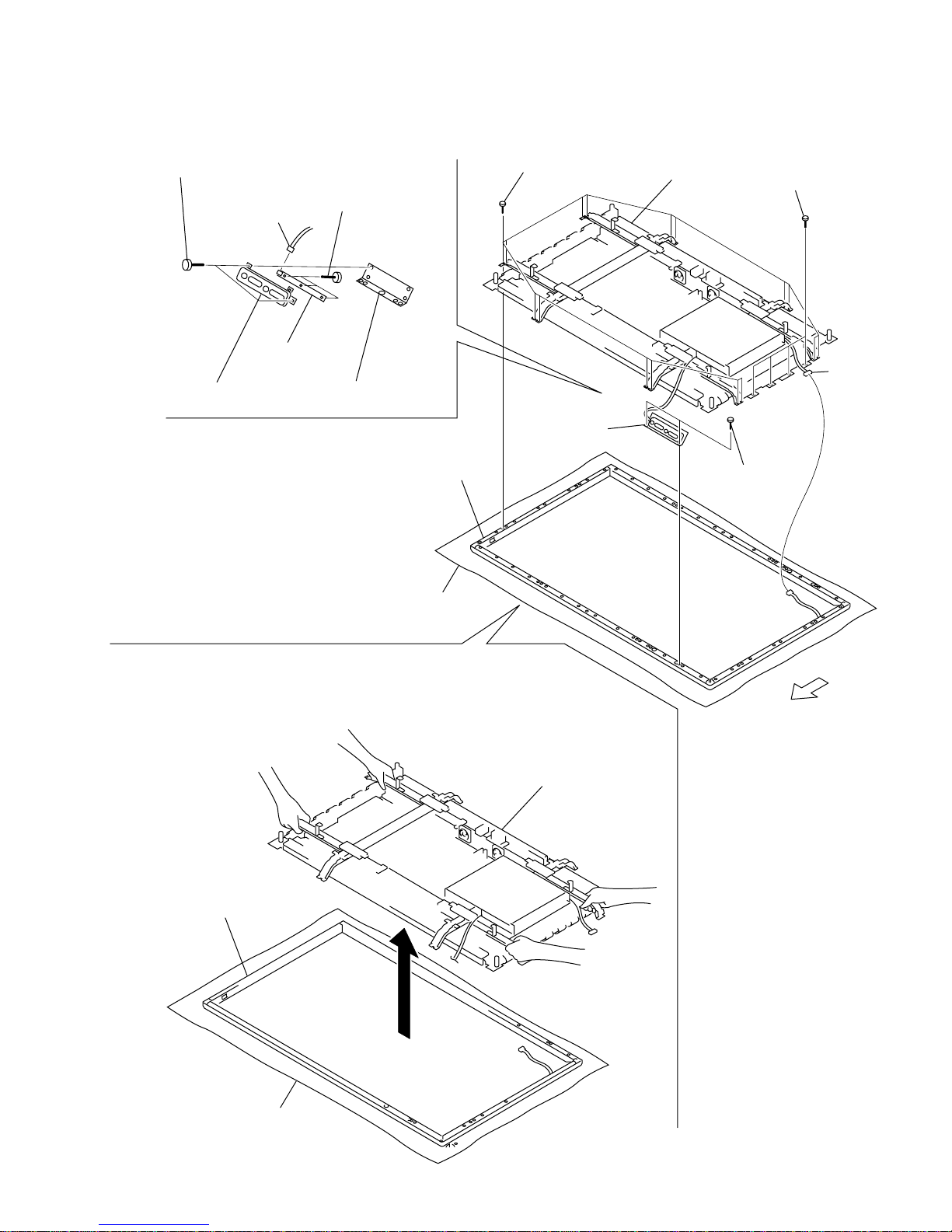
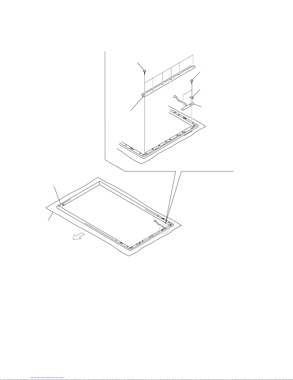
1-12
PFM-50C1/50C1E
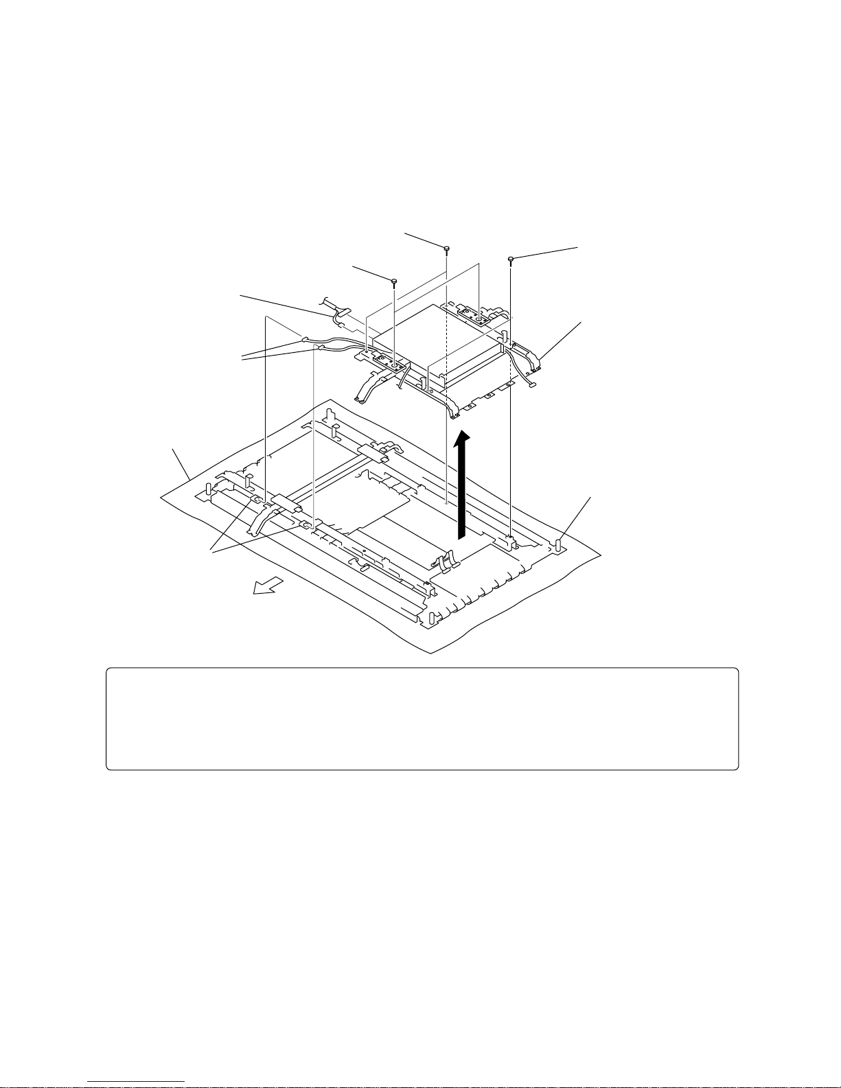
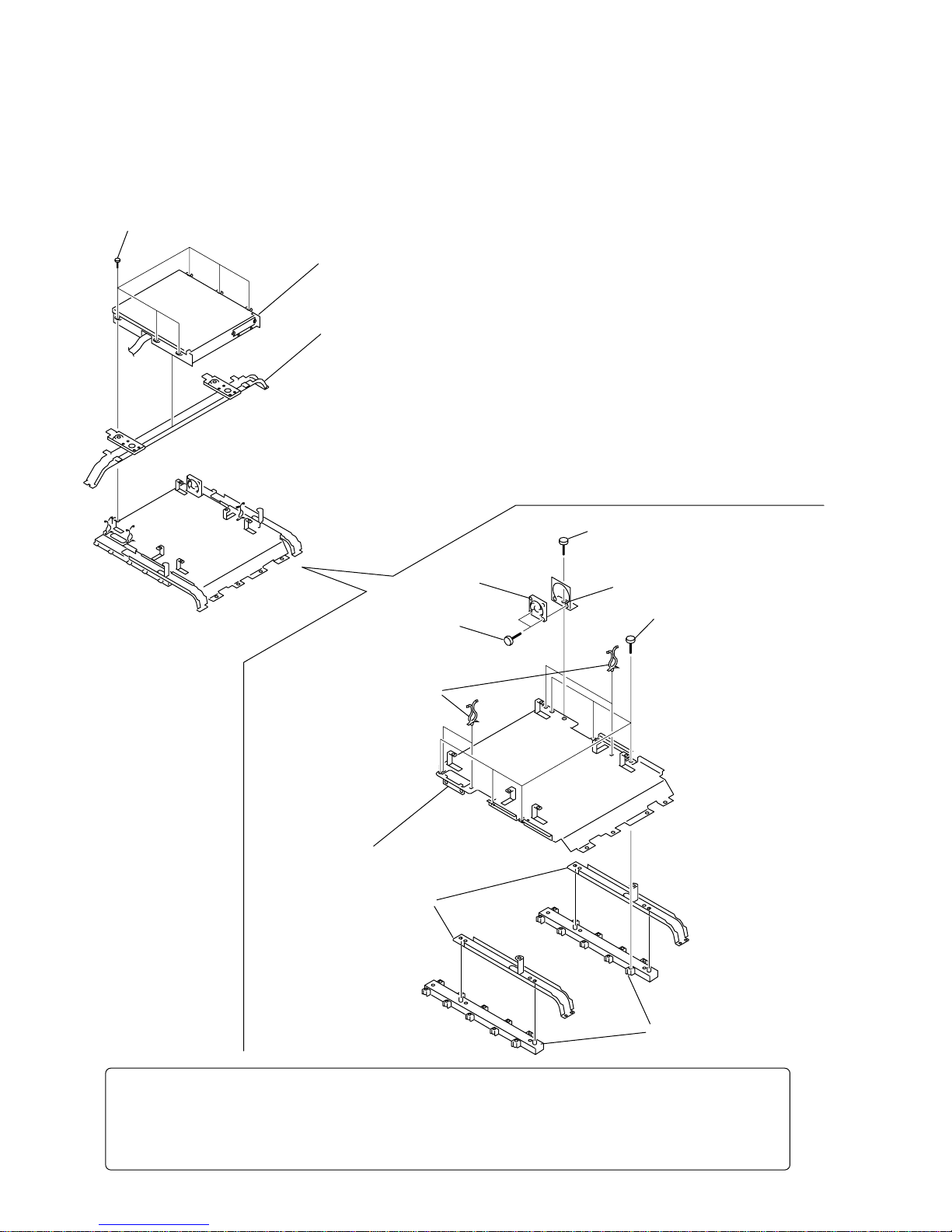
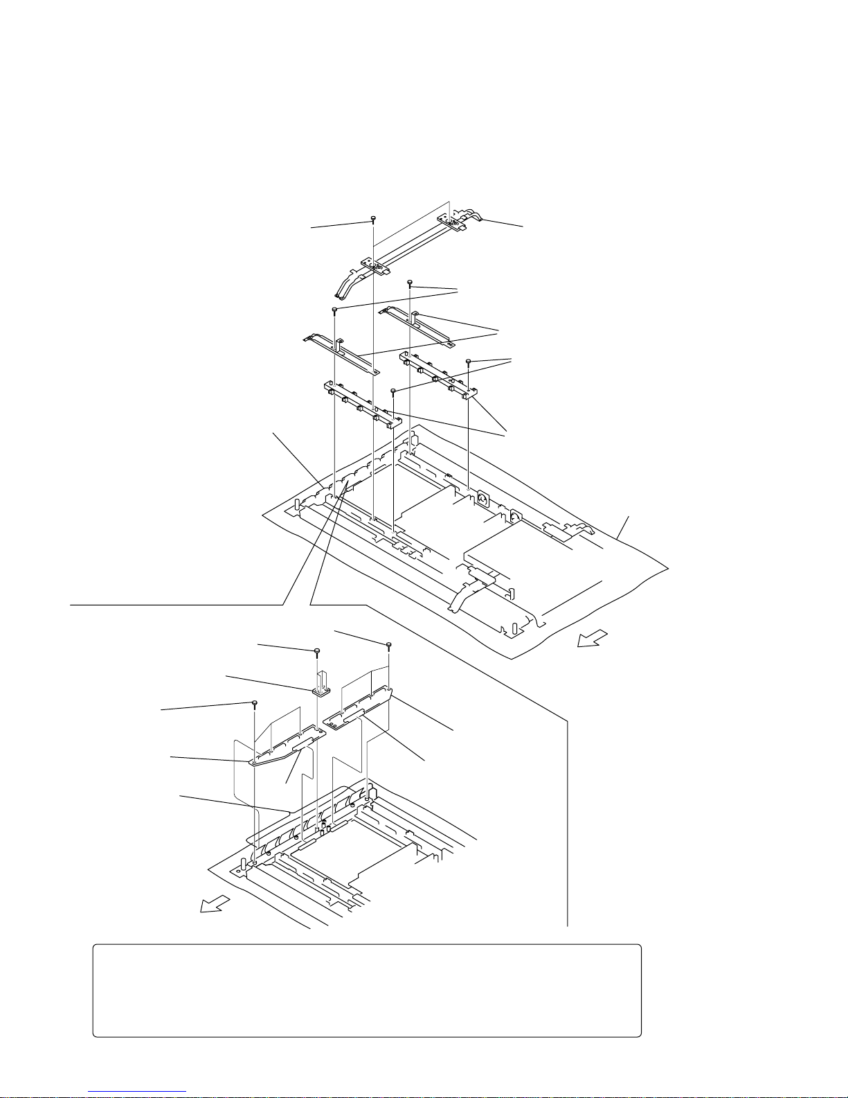
1-2-11.Q/B Bracket Assy Removal
n
To remove the Q/B bracket assy, remove the Bezel block assy, AC inlet block assy, B block assy beforehand.
3 Main frame, Two suspensions
2 B
block assy
6 Two sub frames
!= Q/B
bracket assy
9 DC
fan
0
Fan bracket
(P)
!-
Four purse locks
5
Two
positioning plates
7 Screw
(+PS 3 x 8)
8
Two
screws
(+PSW 3 x 16)
4
Six
screws
(+BVTP 3 x 10)
1
Six
screws
(+PSW 3 x 8)
Note : To remove the Q/B bracket, remove it after the bezel assembly has already removed earlier.
If not, it can result in distortion of bezel assembly and damage of optical filter.
Before starting removal, be sure to remove the operation button assy
from the bezel complete assy. Be very careful not to damage the flexible wires in the top,
bottom, right and left. Place the removed panel on the conductive cushion.
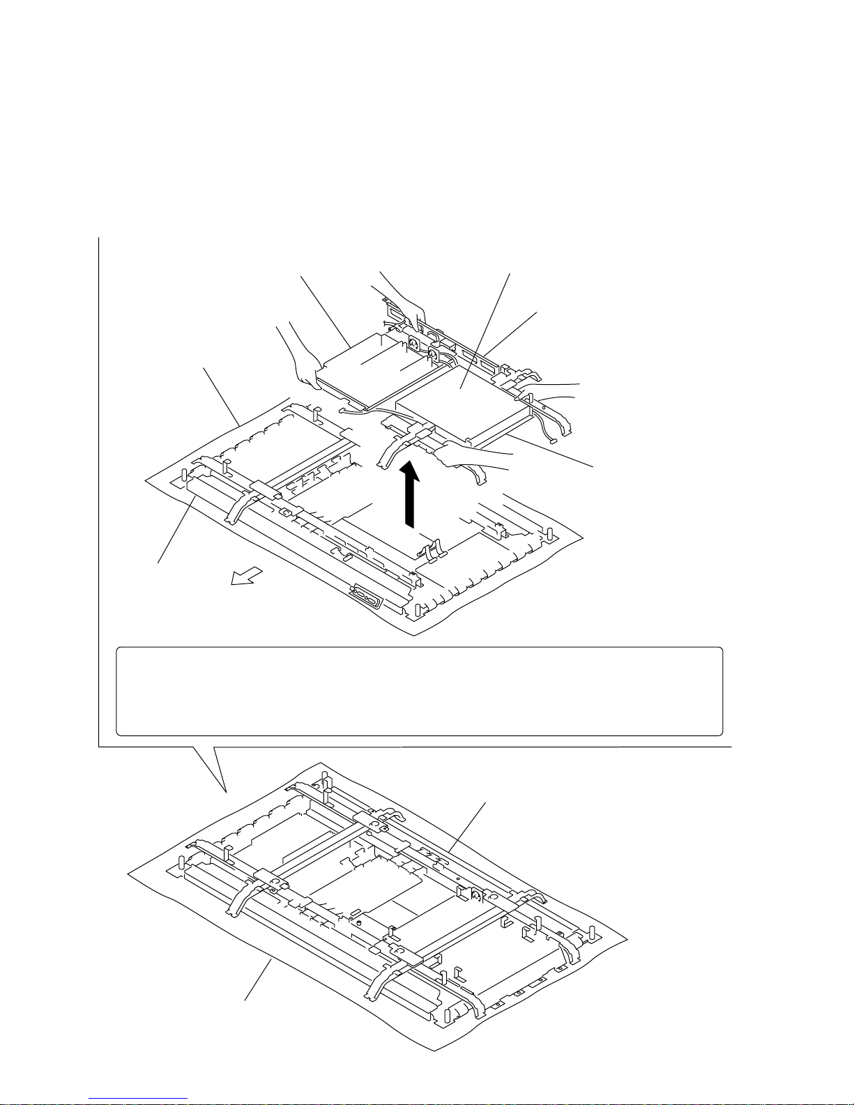
1-13
PFM-50C1/50C1E
Plasma display panel
2
P block assy
1
AC inlet block assy
3 B block assy, Panel assy
Note : When installing the
B block assy and panel assy, install the position setting plate
referring to the “Q/B bracket removal” and determine position
of the Q/B block. After that, install the Q/B block.
Conductive cushion
Conductive cushion
Main chassis
Top side
Note :To remove the plasma display panel, remove it after the bezel assembly has already
removed earlier. If not, it can result in distortion of bezel assembly and
damage of optical filter. Before starting removal, be sure to remove the operation button assy
from the bezel complete assy. Be v ery careful not to damage the flexible wires in the top,
bottom, right and left. Place the removed panel on the conductive cushion.
1-2-12. Plasma Display Panel Removal
m
. When removing the plasma display panel, remove the bezel assembly, AC inlet block assembly, P block assembly, B
block assy and panel assy. Then remove the respective circuit boards that are attached to the panel.
. When removing the main chassis, be sure that the two persons or more must work together for removal.
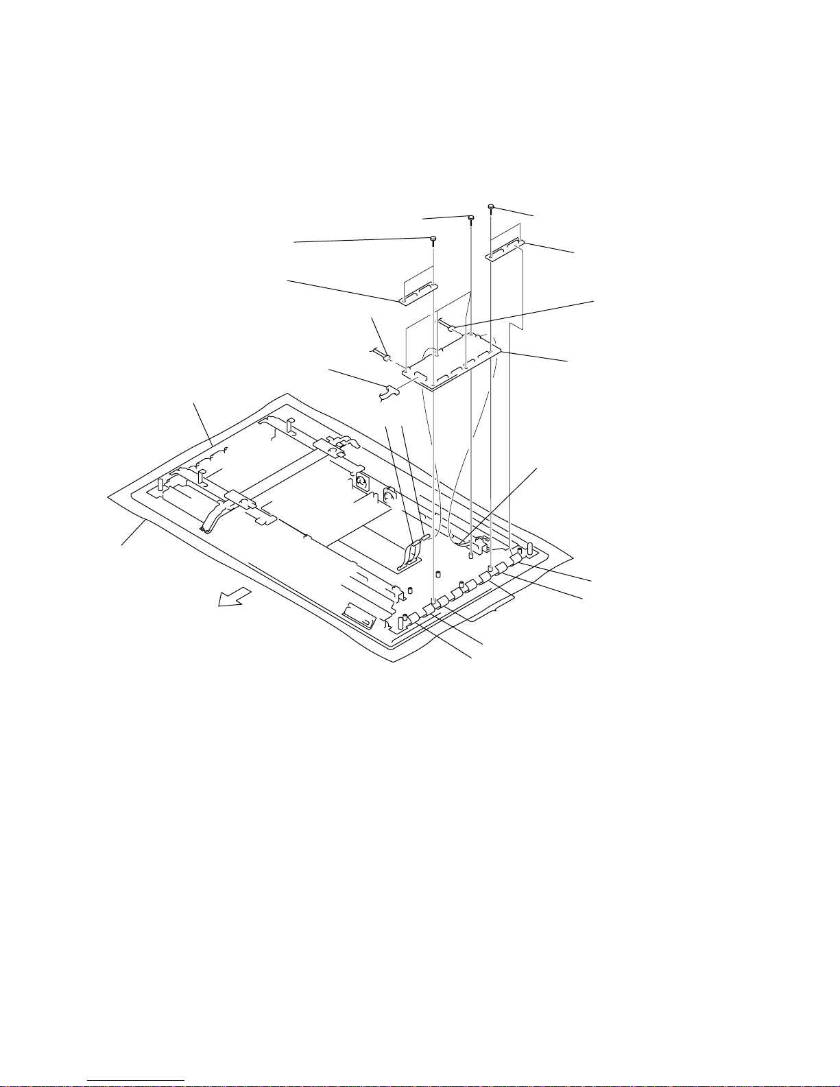
1-14
PFM-50C1/50C1E
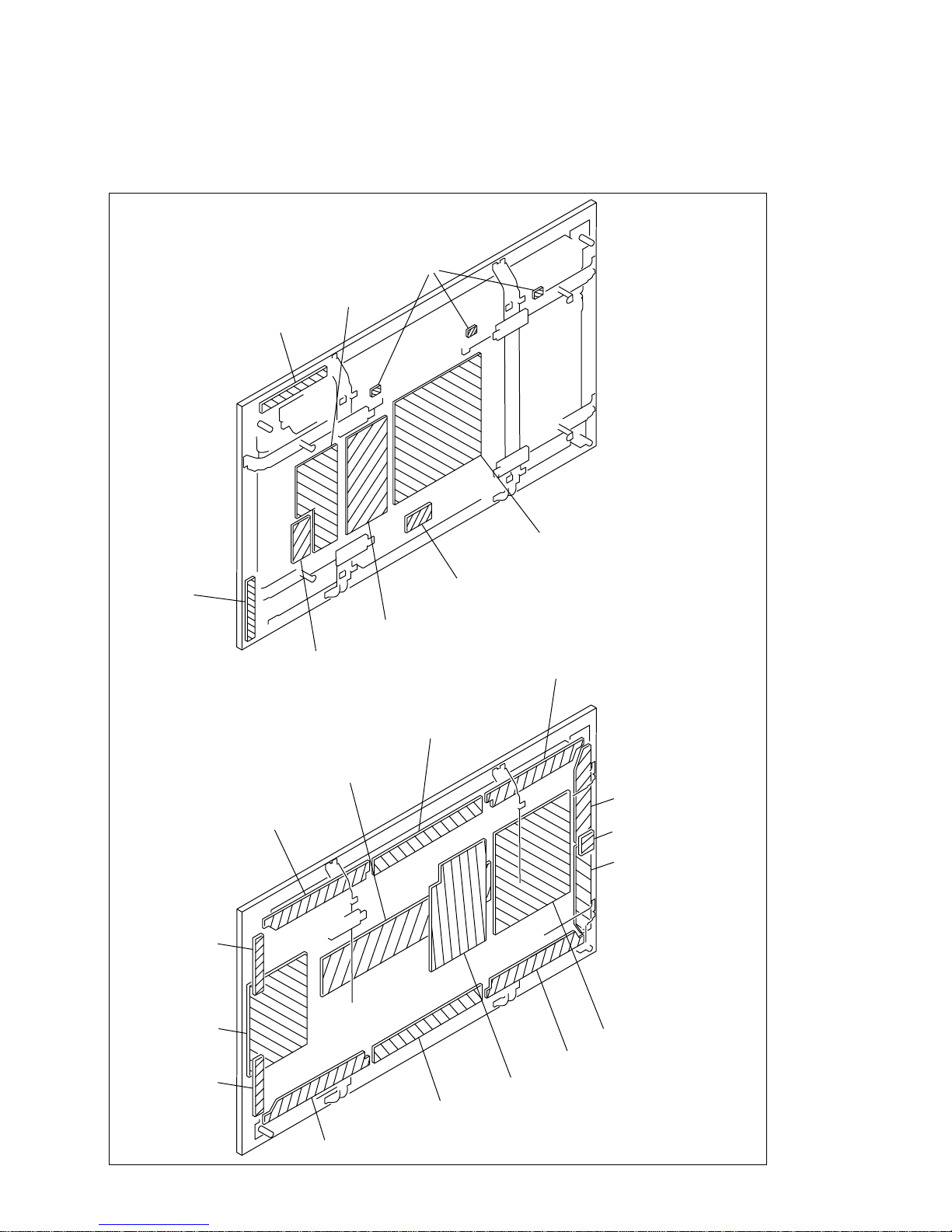
CN1 to CN4
CN7301
CN7303
6 Common PKG board
2 Common joint PKG (U) board
4 Common joint PKG (L) board
CN104
CN12
CN11
3
Two
screws
(+PSW 3 x 8)
1
Two
screws
(+PSW 3 x 8)
5
Four
screws
(+PSW 3 x 8)
CN7
CN8CN6
CN7304
CN7302
Conductive cushion
Main chassis
Top side
1-2-13.Common PKG Board Removal
n
To remove the Common PKG board, remove the AC inlet block assy, B block assy and panel assy
beforehand.
1-15
PFM-50C1/50C1E
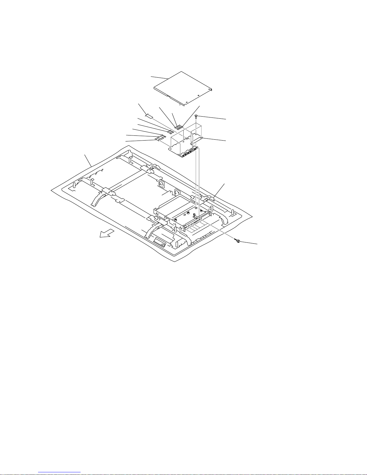
3 Digital PKG board
2 Five screws
(+PSW 3 x 8)
1 Screw (+PSW 3 x 8)
CN904 to CN906
CN901 to CN903
CN751
CN801
CN101
Conductive cushion
Main chassis
Top side
1-2-14.Digital PKG Board Removal
n
To remove the Digital PKG board, remove the P block assy beforehand.
1-16
PFM-50C1/50C1E
2 Collection joint PKG board
1 Five screws
(+PSW 3 x 8)
CN8
CN10
CN9
CN6
Conductive cushion
Main chassis
Top side
1-2-15.Collection Joint PKG Board Removal
n
To remove the collection joint PKG board, remove the AC inlet block assy, B block assy, panel assy,
P block and Digital PKG board beforehand.
1-17
PFM-50C1/50C1E
2 Remove the scan PKG board
in the direction of the arrow.
1
Ten
screws
(+PSW 3 x 8)
CN5
CN7
CN1
CN10
CN9
CN12
CN11
CN6
CN105
Conductive cushion
Main chassis
Top side
1-2-16.Scan PKG Board Removal
n
To remove the scan PKG board, remove the DC fan (R) assy beforehand.
1-18
PFM-50C1/50C1E
5 Two sub frames
6 Two positioning plates
1
Two
screws
(+PSW 4 x 16)
2
Two
screws
(+PSW 4 x 16)
!= Scan joint PKG
(B) board
8 Scan joint- joint PKG board
0 Scan joint PKG
(A) board
7
Four
screws
(+PSW 3 x 8)
CN202 to CN209
9
Three
screws
(+PSW 3 x 8)
!-
Three
screws
(+PSW 3 x 8)
Conductive cushion
Main chassis
4 Main frame, Two suspensions
CN210
CN201
3
Two
screws
(+PSW 3 x 16)
Top side
Top side
Note : To remove the scan joint PKG (A) and (B) boards, remove it after the bezel assembly has
already removed earlier. If not, it can result in distortion of bezel assembly and damage of
optical filter. Before starting removal, be sure to remove the operation button assy
from the bezel complete assy. Be very careful not to damage the flexible wires in the top,
bottom, right and left. Place the removed panel on the conductive cushion.
1-2-17.Scan Joint PKG (A) and (B) Boards Removal
n
To remove the scan joint PKG (A) and (B) board, remove the bezel assy and the DC fan (R) assy beforehand.
1-19
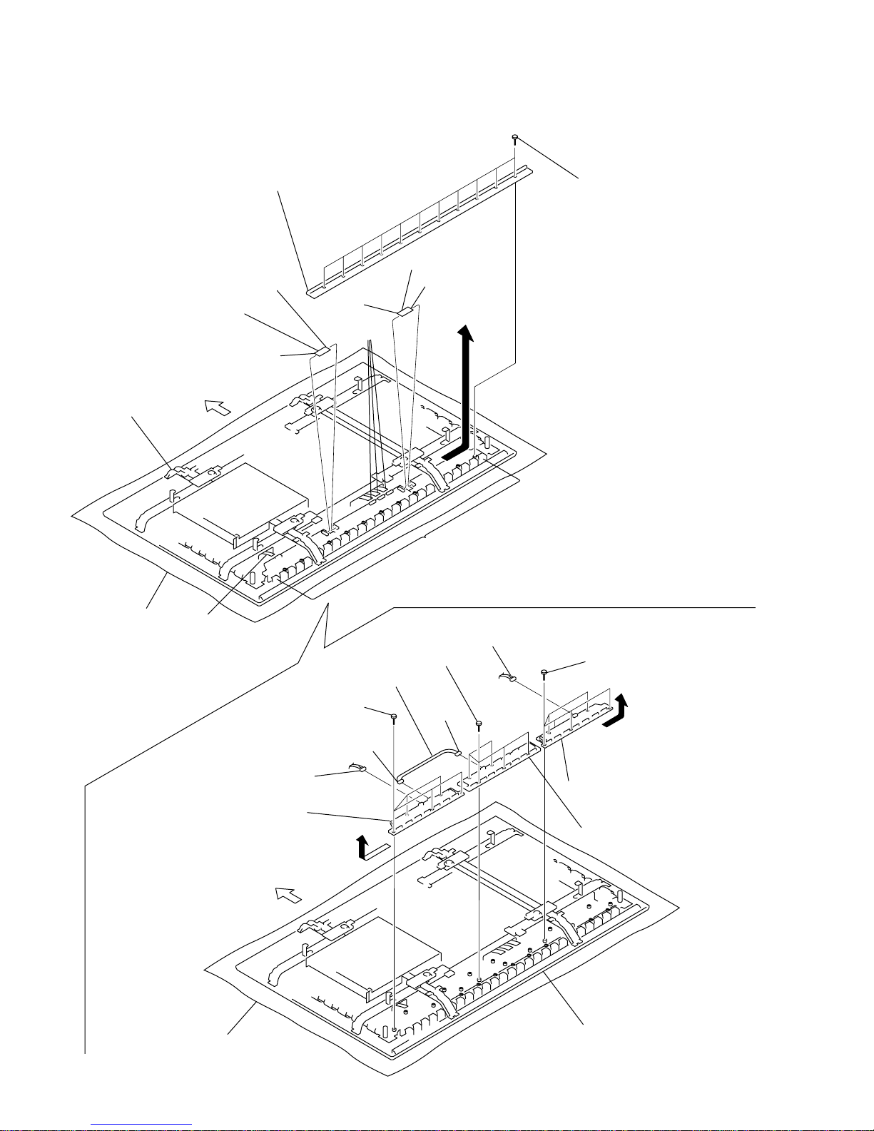
PFM-50C1/50C1E
1 Eleven screws
(+PSW 3 x 8)
2 Remove the flexible board retaining
bracket in the direction of the arrow A.
3 FFC50C2-01
4 FFC50C2-01
CN1 to CN3
CN8
CN5
CN1
CN4
CN1 to CN22
6 Five screws
(+PSW 3 x 8)
8 Five screws
(+PSW 3 x 8)
0 Five screws
(+PSW 3 x 8)
7 Remove the signal joint PKG (LU)
board in the direction of the arrow B.
CN2
CN10
!- Remove the signal joint PKG
(RU) board in the direction
of the arrow C.
9 Signal joint PKG (MU) board
CN3
CN6
Conductive cushion
Main chassis
Conductive cushion
Main chassis
5 CBL50C2-04
Top side
Top side
A
B
C
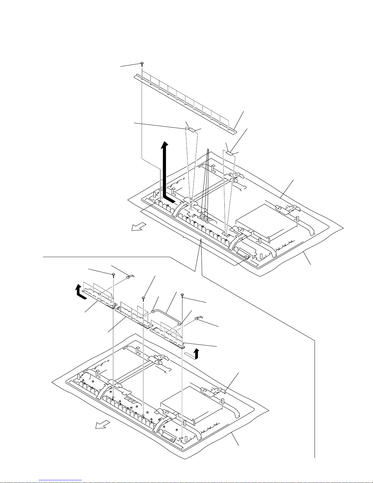
1-2-18.Signal Joint PKG (RU), (MU), (LU) Board Removal
1-20
PFM-50C1/50C1E
CN8
CN9
3 FFC50C2-01
4 FFC50C2-01
CN1
to
CN3
CN4
CN5
CN1
6 Five screws
(+PSW 3 x 8)
8 Five screws
(+PSW 3 x 8)
0 Five screws
(+PSW 3 x 8)
7 Remove the signal joint PKG (LL)
board in the direction of the arrow B.
CN2
CN6
CN11
CN10
9 Signal joint PKG (ML) board
2 Remove the flexible board retaining
bracket in the direction of the arrow A.
1 Eleven screws
(+PSW 3 x 8)
Conductive cushion
Main chassis
Conductive cushion
Main chassis
CN1
to
CN22
!- Remove the signal joint PKG (RL)
board in the direction of the arrow C.
5 CBL50C2-04
Top side
Top side
A
B
C
1-2-19.Signal Joint PKG (RL), (ML), (LL) Board Removal

1-21
PFM-50C1/50C1E
3 Four knobs
1 Q/B shield cover
2 Four screws
(+PSW 6 x 20)
4 Main chassis
Main chassis
5
Two
stands
7 The stand is attached
inside the PDP panel.
Direction of
the two suspensions.
6 Insert the four knobs
into the holes of the stand.
1-3. Service Position
1-3-1. Service Position of Q Board
n
When you are going to set up the PDP panel in the service position, remove the rear cover first, and then
set up the PDP panel in the service position.
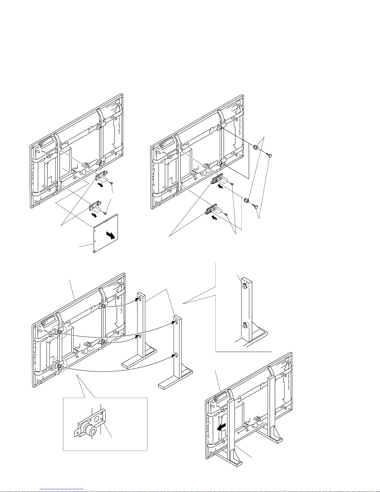
1-22
PFM-50C1/50C1E
1 Q/B shield cover
2 Six screws
(+PSW 4 x 8)
3 T wo suspensions
8 Main chassis
Main chassis
9 T wo suspensions
!- The stand is attached
outside the PDP panel.
Direction of installation
of the two suspensions.
!/Insert the four knobs
into the holes of the stand.
5 Six screws
(+PSW 4 x 8)
4 T wo suspensions
6 Four knobs
7 Four screws
(+PSW 6 x 20)
1-3-2. Service Position of B Board
n
When you are going to set up the PDP panel in the service position, remove the rear cover first, and then
set up the PDP panel in the service position.
 Loading...