

Page 1
PFM-50C1/50C1E
4-089-578-04 (2)
Flat Panel Display
取扱説明書
Operating Instructions
Mode d’emploi
Bedienungsanleitung
Manual de instrucciones
Istruzioni per l’uso
使用说明书
お買い上げいただきありがとうございます。
この取扱説明書には、事故を防ぐための重要な注意事項と製品の取り扱
いかたを示してあります。この取扱説明書をよくお読みのうえ、製品を
安全にお使いください。お読みになったあとは、いつでも見られるとこ
ろに必ず保管してください。
電気製品は安全のための注意事項を守らないと、
火災や人身事故になることがあります。
JP
GB
FR
DE
ES
IT
CS
PFM-50C1/50C1E
2002 Sony Corporation
Page 2
安全のために
ソニー製品は安全に充分配慮して設計されています。しかし、電気製品は、
まちがった使いかたをすると、火災や感電などにより死亡や大けがなど人身
事故につながることがあり、危険です。
事故を防ぐために次のことを必ずお守りください。
安全のための注意事項を守る
5(JP)〜 7(JP)ページの注意事項をよくお読みください。
8(JP)ページの「本機の性能を保持するために」もあわせてお読みください。
警告表示の意味
取扱説明書および製品では、次の
ような表示をしています。表示の
内容をよく理解してから本文をお
読みください。
定期点検をする
5年に1度は、内部の点検を、お買い上げ店またはソニーのサービス窓口に
ご依頼ください(有料)。
故障したら使わない
すぐに、お買い上げ店またはソニーのサービス窓口にご連絡ください。
万一、異常が起きたら
・煙が出たら
・異常な音、におい
がしたら
・内部に水、異物が
入ったら
・製品を落としたり
キャビネットを破
損したときは
,
1 ディスプレイの電源を切る。
2 ディスプレイの電源コードや接続
コードを抜く。
3 お買い上げ店またはソニーの
サービス窓口に連絡する。
この表示の注意事項を守らないと、
火災や感電などにより死亡や大け
がなど人身事故につながることが
あります。
この表示の注意事項を守らないと、
感電やその他の事故によりけがを
したり周辺の物品に損害を与えた
りすることがあります。
注意を促す記号
この装置は、情報処理装置等電波障害自主規制協議会(VCCI)の基準に基づくクラス
B情報技術装置です。この装置は、家庭環境で使用することを目的としていますが、この
装置がラジオやテレビジョン受信機に近接して使用されると、受信障害を引き起こすこと
があ ります。
取扱説明書に従って正しい取り扱いをしてください。
(JP)
2
行為を禁止する記号
行為を指示する記号
Page 3

目次
................................................................................... 5(JP)
................................................................................... 6(JP)
電池についての安全上のご注意 ............................................. 7(JP)
万一、異常が起きたら ....................................................................... 7(JP)
本機の性能を保持するために .................................................8(JP)
特長 .......................................................................................... 8(JP)
各部の名称と働き .................................................................... 9(JP)
前面/後面/右側面 ........................................................................ 9(JP)
1(ス タンバイ) スイ ッチ/イ ンジケーター部 .................................... 10(JP)
コン トロールボタン部(上面)........................................................... 10(JP)
入出力端子パネル .......................................................................... 11(JP)
リモートコマンダー RM-971 .............................................................. 13(JP)
使用上のご注意..................................................................... 15(JP)
接続 ....................................................................................... 16(JP)
スピーカーの接続 ............................................................................ 16(JP)
電源コードの接続 ............................................................................ 16(JP)
接続例 ............................................................................................. 16(JP)
フェライトコアの取 り付け ................................................................... 19(JP)
メニューで行う調整と設定 .................................................. 21(JP)
メニューの操作 ................................................................................ 21(JP)
メニューの説明 ................................................................................ 21(JP)
JP
日
本
語
画像を見る ............................................................................ 29(JP)
入力信号を切り換える ..................................................................... 29(JP)
入力信号と画質モードの情報とディ スプレイ の設定状態の
表示について ............................................................................ 30(JP)
画面表示を切り換える ..................................................................... 32(JP)
節電モード機能 ................................................................................ 32(JP)
画質を選ぶ ............................................................................ 33(JP)
画質を調整する..................................................................... 33(JP)
コン トラスト、明るさ、色の濃さ 、色あいなどを調整する................... 33(JP)
調整した画質を 出荷時の設定値に戻す ......................................... 36(JP)
映像を拡大する..................................................................... 37(JP)
オートワイドを設定する ..................................................................... 37(JP)
ワイド切換を設定する ...................................................................... 38(JP)
画像のサイズや位置を調整する .......................................... 39(JP)
画像のサイズを変える ..................................................................... 39(JP)
画像の位置を調整する ................................................................... 39(JP)
ドッ ト位 相を調整する........................................................................ 40(JP)
設定した 画面モードメニューの調整値 を出荷時の設定値 に戻す..40(JP)
音質を調整する..................................................................... 41(JP)
3
(JP)
Page 4

高音、低音、 バラ ンスなど を調整する............................................. 41(JP)
調整した音質を出荷時の設定に戻す............................................. 41(JP)
メモリーを使う..................................................................... 42(JP)
現在の調整状態をメモリーする....................................................... 42(JP)
メモリ ーし た設定値を呼び出す....................................................... 43(JP)
メニュー表示の言語を選ぶ .................................................. 43(JP)
スクリーンセーバー機能...................................................... 44(JP)
画像の色あいを反転させる ............................................................. 44(JP)
画像の表示位置を自動的に変える .................................................45(JP)
カラーマトリクスを調整する .............................................. 45(JP)
電源のオン/オフを自動的に制御する(タイマー機能)...... 46(JP)
スリープ機能 .................................................................................... 46(JP)
時刻 を設定する............................................................................... 47(JP)
時計 を表示する............................................................................... 47(JP)
電源タイマー機能 ............................................................................ 47(JP)
パワーセービング機能 ..................................................................... 48(JP)
自己診断機能 ........................................................................ 49(JP)
特定のディスプレイをリモートコマンダーで操作する ..... 49(JP)
他のリモートコマンダーから操作する ............................... 51(JP)
仕様 ....................................................................................... 52(JP)
保証書とアフターサービス .................................................. 54(JP)
4
(JP)
Page 5
設置・取り付けは確実に
火災
感電
下記の注意を守らないと、
火災や感電により死亡や大けがに
つながることがあります。
規定の電源電圧で使う
この取扱説明書に記されている電源電圧でお
使いください。
規定外の電源電圧での使用は、火災や感電の
原因となります。
油煙、湯気、湿気、ほこりの多い場所では設
置・使用しない
上記のような場所に設置すると、火災や感電
の原因となります。
この取扱説明書に記されている仕様条件以外の
環境での使用は、火災や感電の原因となります。
分解や改造をしない
分解や改造をすると、火災や感電、けがの原
因となることがあります。
内部の点検や修理は、お買い上げ店またはソ
ニーのサービス窓口にご依頼ください。
電源コードを傷つけない
電源コードを傷つけると、火災や感電の原因
となります。次の項目を必ずお守りください。
・ 設置時に、製品と壁やラック、棚などの間
に、はさみ込まない。
・ 電源コードを加工したり、傷つけたりし
ない。
・ 重いものをのせたり、引っ張ったりしない。
・ 熱器具に近づけたり、加熱したりしない。
・ 電源コードを抜くときは、必ずプラグを
持って抜く。
万一、電源コードが傷んだら、お買い上げ店
またはソニーのサービス窓口に交換をご依頼
ください。
不確実な設置を行うと、ディスプレイが転倒
してけがや火災・感電の原因となります。設
置の際は、以下の注意事項を必ずお守りくだ
さい。
壁面・天井・台上への設置、または転倒防
止のためディスプレイを固定するなど、特
殊な設置を行う場合には、必ずお買い上げ
店に工事を依頼してください。
衝撃を与えない
本機の前面にガラスを使用しているため、衝
撃を与えるとガラスが割れ、けがの原因とな
ることがあります。
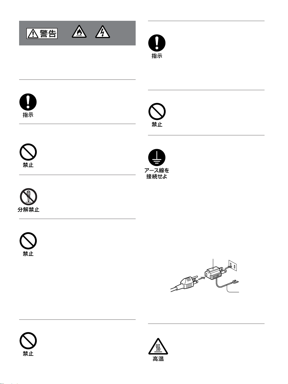
安全アースを接続する
安全アースを接続しないと、感電の原因とな
ることがあります。次の方法でアースを接続
してください。
・ 電源コンセントが 3 極の場合
付属の電源コードを使用することで、安全
アースが接続されます。
・ 電源コンセントが 2 極の場合
付属の3 極→2極の変換プラグアダプター
を使用し、変換プラグアダプターから出て
いる緑色のアースを、建物に備えられてい
るアース端子に接続する。
・ アース接続は、必ず電源プラグを電源につ
なぐ前に行ってください。
また、アース接続をはずす場合は、必ず電
源プラグを電源から切り離してから行って
ください。
変換プラグアダプター
アース線
不明な点はお買い上げ店またはソニーのサー
ビス窓口にご相談ください。
内部に水や異物をいれない
水や異物が入ると火災や感電の原因となるこ
とがあります。
万一、水や異物が入ったときは、すぐに電源
を切り、電源コードや接続コードを抜いて、
お買い上げ店またはソニーのサービス窓口に
ご相談ください。
高温部分に触れない
機器を使用中または使用直後には上面や側面
が高温になっているため、やけどをすること
があります。
使用中および電源を切るまたはスタンバイし
た状態から 10 分間は触れないでください。
5
(JP)
Page 6
下記の注意を守らないと、
けがをしたり周辺の物品に損害を与える
ことがあります。
重いディスプレイは、2人以上で開梱・運搬する
ディスプレイは見た目より重量があります。
開梱・運搬は、けがや事故を防ぐため、必ず
2人以上で行ってください。1人で行うと腰を
痛めることがあります。
ぬれた手で電源プラグをさわらない
ぬれた手で電源プラグを抜き差しすると、感
電の原因となることがあります。
水のある場所に設置しない
水が入ったり、ぬれたりすると、火災や感電
の原因となることがあります。雨天や降雪
中、海岸や水辺での使用は特にご注意くだ
さい。
通風孔をふさがない
通風孔をふさぐと内部に熱がこもり、火災や
故障の原因となることがあります。風通しを
よくするために次の項目をお守りください。
・ 使用上のご注意の項(15(JP)ページ)に
従って設置してください。
・ 密閉された狭い場所に押し込めない。
・ 毛足の長い敷物(じゅうたんや布団など)
の上に設置しない。
・ 布などで包まない。
・ あお向けや横倒し、逆さまにしない。
設置時には必ずスタンドを使用する
ディスプレイの転倒によるけがや事故を防ぐ
ため、台・床などに本機を据え置きする際は、
別売りの専用スタンド(SU-P50C)をご使用く
ださい。
設置時には転倒防止処置を行う
本機を据え置きする際には天災・地震など万
一の場合に備え、転倒防止処置を行ってくだ
さい。
直射日光の当たる場所や熱器具の近くに設
置・保管しない
不安定な場所に設置しない
ぐらついた台の上や傾いたところなどに設置
すると、ディスプレイが落ちたり、倒れたり
して、けがの原因となることがあります。
また、設置・取り付け場所の強度を充分にお
確かめください。
接続の際は電源を切る
電源コードや接続ケーブルを接続するとき
は、電源を切ってください。感電や故障の原
因となることがあります。
指定された電源コード、接続ケーブルを使う
付属の、あるいは取扱説明書に記されている
電源コード、接続ケーブルを使わないと、感
電や故障の原因となることがあります。
他の電源コードや接続ケーブルを使用する場
合は、お買い上げ店またはソニーのサービス
窓口にご相談ください。
内部の温度が上がり、火災や故障の原因とな
ることがあります。
真夏の、窓を閉め切った自動車内では 50℃を
超えることがありますので、ご注意ください。
電源コードのプラグおよびコネクターは突き
当たるまで差し込む
まっすぐに突き当たるまで差し込まないと、
火災や感電の原因となります。
お手入れの際は、電源を切って電源プラグを
抜く
電源を接続したままお手入れをすると、感電
の原因となることがあります。
6
(JP)
Page 7
移動させるときは電源コード、接続ケーブル
を抜く
接続したまま移動させると、電源コードや接
続ケーブルが傷つき、火災や感電の原因とな
ることがあります。
電池についての安全上の
ご注意
ここでは、本機での使用が可能なソニー製アルカリ乾電池に
ついての注意事項を記載しています。
定期的に内部の掃除を依頼する
長い間、掃除をしないと内部にホコリがたま
り、火災や感電の原因となることがありま
す。1年に1度は、内部の掃除をお買い上げ
店またはソニーのサービス窓口にご依頼くだ
さい(有料)。
特に、湿気の多くなる梅雨の前に掃除をする
と、より効果的です。
人が通行するような場所に置かない
コード類は正しく配置する
電源コードや信号ケーブルは、足に引っかけ
ると製品の落下や転倒などによりけがの原因
となることがあります。人が踏んだり、引っ
かけたりするような恐れのある場所を避け、
十分注意して接続・配置してください。
コード類は正しく配置する
電源コードや接続ケーブルは、足に引っかけ
ると本機の落下や転倒などによりけがの原因
となることがあります。
十分注意して接続・配置してください。
万一、異常が起きたら
すぐにきれいな水で洗い、ただ
電池の液が目に
入ったら
煙が出たら
電池の液が皮膚や
衣服に付いたら
バッテ リー収納部内
で液が漏れたら
死亡や大けがなどの人身事故になることがあ
ります。
・ 乾電池は充電しない。
・ 火の中に入れない。ショートさせたり、分
解、加熱しない。
・ 指定された種類の電池を使用する。
,
ちに医師の治療を受ける。
1 電池を抜く。
,
2 お買い上げ店またはソニー
のサービス 窓口に連絡する 。
すぐにきれいな水で洗い流す。
,
よくふき取って から、新しい電
,
池を入れる。
下記の注意事項を守らないと、
破裂・発熱・液漏れにより、
下記の注意事項を守らないと、
破裂・液漏れにより、けがをし
たり周辺の物品に損害を与えたりする
ことがあります。
・ 投げつけない。
・ 使用推奨期限内(乾電池に記載)の乾電池
を使用する。
・ 3 と # の向きを正しく入れる。
・ 電池を入れたまま長期間放置しない。
・ 新しい電池と使用した電池は混ぜて使わな
い。
・ 種類の違う電池を混ぜて使わない。
・ 水や海水につけたり濡らしたりしない。
(JP)
7
Page 8

本機の性能を保持するために/特長
本機の性能を保持するた
めに
PDP(プラズマディスプレイパネル)について
・画面上に赤や青、緑の点(輝点)が消えなかったり、黒い点(滅
点)があ る場合があります が、故障ではありません。パネルは非
常に精密な技術で作られており、ごくわずかの画素欠けや常に
点灯する画素がある場合があります。ご了承ください。 また、画
面の上下端および左右端に常に光らない部分がありますが、故
障ではありません。また、すじ状の色むらや明るさのムラが見え
る場合も あ り ますが、故障ではあ り ません。
・高山地など気圧の低いところで使用するとプラズマディスプレイ
パネルの構造上、ブーン音(バズ音)が発生することがありま
す。
・一定時間同じ画像を表示し続けると、部分的に残像や焼きつき
が発生することがあります。
一定時間画像を 表示し続けるときは、画面の焼きつき を避けるた
め、本機のスクリーンセーバー機能を使用し、全画面表示してく
ださい。焼きつき が発生したとき は、本機の スクリーンセ ーバー機
能を使用するか、ビデオソフトなど の 動きのある映像を映してく だ
さい。焼きつきが軽度のときは、次第に目立たなくなる こ とがあり
ますが、一度発生した焼きつきは、完全には消えません。
・本機はプラズマディスプレイの保護のため電源ON/STANDBY
に時間をかけてお り、その間 リモコ ンおよび本体の操作ボタンに
よる操 作を受け 付けません。約8秒待ってから操作をしてくださ
い。
設置についてのご注意
他の機器と組み合わせて設置する場合、各機器の設置位置など
によ り 、リモートコマンダーの誤動作や映像の乱れ、雑音などが起
こることがあります 。この場合は、 お買い上げ店、またはソニーの
サー ビス窓口にご連絡ください。
クリーニングについて
・お手入れの際は、必ず本機の電源を 切って 電源 プラグを抜いて
ください。
・シンナーやベンジンなどの薬品類は、表面の仕上げを傷めたり、
表示が消えてしまうことがあります の で 、 使用しないでください。
ディスプレイのガラス表面の取扱いについての
ご注意
特長
本機は、PDP(プラ ズマデ ィスプレイ パネル)を使用 し た薄型50型
の16:9マルチメディア対応ディスプレイです。
高画質・高精細
PFM-50C1は水平1365ドット× 垂 直 768ラインの高精細プラズマ
ディ スプレイパネルを採用。さまざまな映像ソースを高画質で再現
します。
ソニー独自のデジタル高画質回路
すべての映像信号をデジタルで一貫処理することにより高品質で
リア ルな画 像を 再 現します。
オーディオアンプ・スピーカーアウトを搭載
高音質デジ タルアンプを搭載。オプシ ョンス ピーカーとの組み合わ
せにより効果的なプレゼンテーションを実現します。
その他の特長
・シネマ ドライ ブモード機能搭載。
・スピーカーアウト(L/R)を装備。
・コントロールS(IN/OUT)を装備。
・RGB/コンポーネント入 力2系統の映像入力を装備。
・3値同期信号付きHDTV信号の表示が可能。
・NTSC方式のY/C分離に3次元くし形フィルターを使用。
・PAL方式のY/C分離にデジタルくし形フィルターを使 用。
・入力信号を自動判別して表示。
1)
・Windows
・ダイナミックピクチャー機能搭載。
・様々 な調整や設定が可能なオンスクリーンメニ ュー 機 能。
・メニュー画面の表示を英語、ドイ ツ語、フランス語、イタリア語、ス
ペイン語、 日本語の6言語から選択可能。
・画像サイズ、位置の微調整が可能。
・20種類の画像設定をメモリー可能。
・IDコントロール機能搭載。
・自己診断機能搭載。
・REMOTE(RS-232C)用端子(D-sub9ピン)を装備。
・SIRCS方式の ソニーのリモートコマン ダー(ワイ ヤレス)を使用可能。
・縦設置のレイアウトも可能。
・クローズドキャプシ ョ ンデコー ダー搭載。
・残像を低減させるスクリーンセーバー機能搭載。
・オプシ ョンス ロ ットを装備 し 、将来の機能拡張に対応しています。
オプションアダプターはスロ ットイン方式で、迅速かつ手軽にシス
テムアップが 可能 です。
95/98PnP(プラグアンドプレイ ) に対応 。
ディスプレイの表面は傷つきやすいので、硬いものでこすっ
たり、たたいたり、ものをぶつけたりしないでください。
............................................................................................................................................................................................................................................................
1)Windowsは米国MicrosoftCorporationの米国およびその他の国における登録商標です。
(JP)
8
Page 9
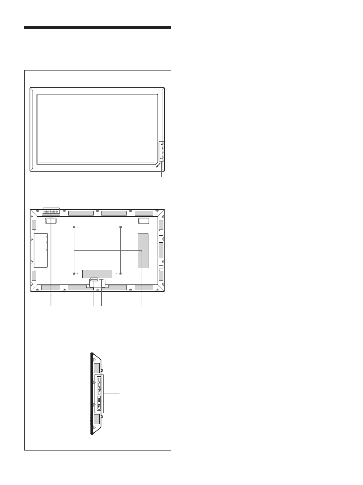
各部の名称と働き
前面/後面/右側面
前面
各部の名称と働き
1 1(スタンバイ)スイッチ/インジケーター部
◆ 1(スタンバイ)スイ ッチ/イ ンジケーター部について詳しくは、「1(ス
タンバ イ)スイ ッチ/イ ンジケーター部」(10(JP)ページ)をご覧くださ
い。
2 コントロールボタン部
◆コントロールボタン部について詳しくは、「コ ントロールボタ ン部(上面)」
(10(JP)ページ)をご覧く ださい。
3 -ACIN(電源入力)端子
付属の電源コードを使用して、AC電源に接続します。AC電源に
接続すると、STANDBYインジケーターが 赤色に点灯し、本機はス
タンバイ状態になります。
◆電源コードの接続について詳し くは、「電源コードの接続」(16(JP)
ペー ジ)をご覧く ださい。
後面
2
斜線部分は通風孔です。
ON
STANDBY
4 SPEAKER(スピーカー)端子
スピーカー (別売り)を接続すると、画面に表示されている信号の
音声を出力します。
1
5 スタンド取り付け用フック
スタン ド(別売り)を取り付けるとき に使用します。
6 入出力端子パネル
◆入出力端子パネルについて詳しくは、「入出力端子パネル」(11(JP)
ペー ジ)をご覧く ださい。
34
5
右側面
6
9
(JP)
Page 10
各部の名称と働き
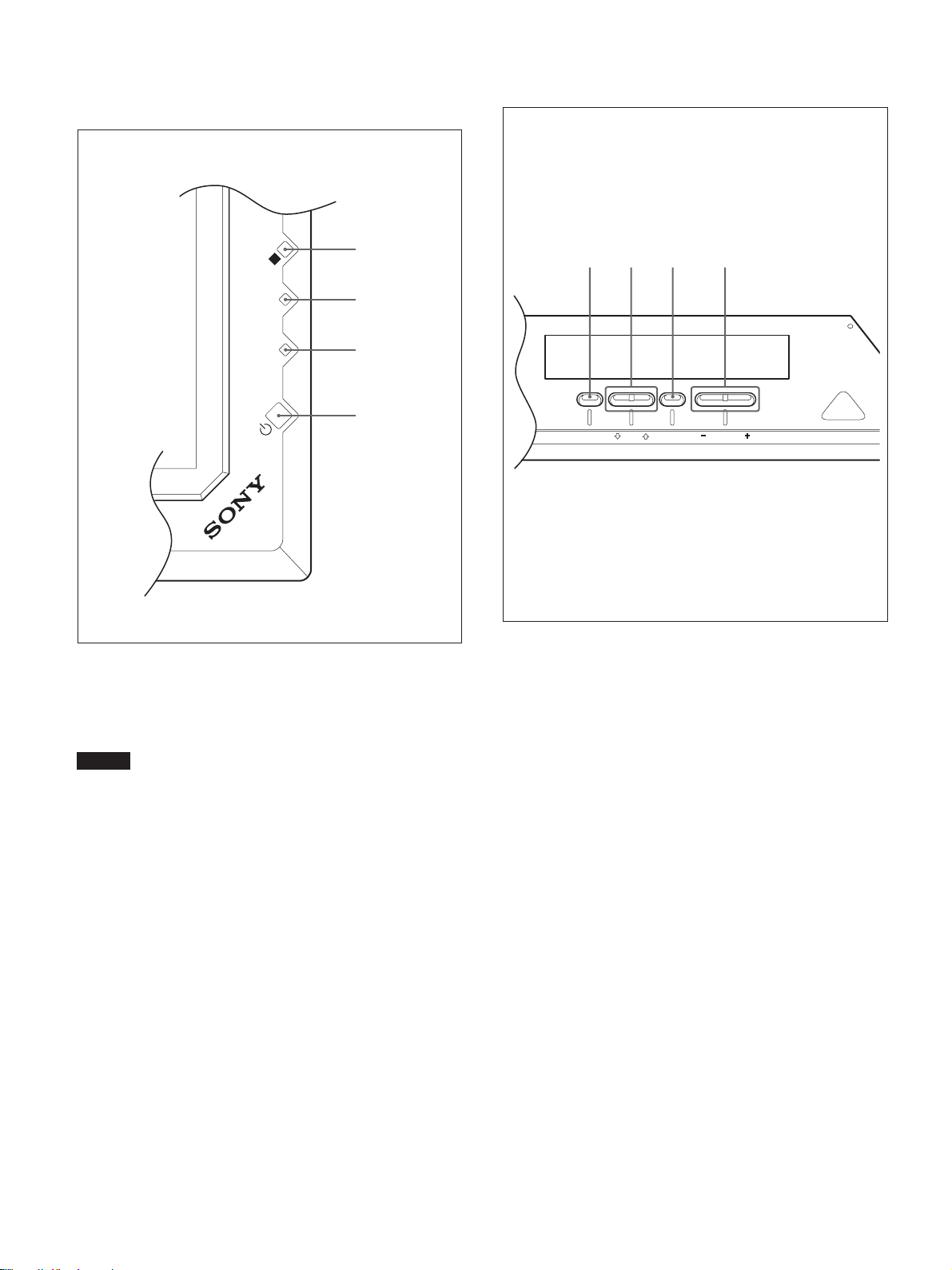
1(スタンバイ)スイッチ/インジ
ケーター部
4
N
O
Y
B
D
N
A
T
S
3
2
1
コントロールボタン部(上面)
123 4
MENU ENTER VOLUME
1 1(スタンバイ)スイッチ
スイ ッチを押すと電源が入り、もう1度押すとスタンバイ状態に戻り
ます。
ご注意
パネル保護のため電源ON/STANDBYに時間がかかります。約
8秒待ってから押してください。
2 STANDBY(スタンバイ)インジケーター
スタンバイ状態 のとき、インジケーターが 赤色に 点灯します。
◆ STANDBYインジケーターが点滅したときは 、「自己診断機能」(49
(JP)ページ)をご覧く ださい。
3 ON(電源)インジケーター
モニ ターの電源を 入れると緑色に点灯します。
4 リモコン受光部
ここでリモートコマンダーの信号を受けます。
1 MENU(メニュー)ボタン
画面にメニューを出すときに使用します。もう一度押すとメニュー
が消えます。
◆ MENUボタンをメニューの階層を戻すために使用する場合は、「初期
設定メニュー」(26(JP)ページ)をご 覧く ださ い。
2 m/Mボタン
メニューでカーソル (黄色)を移動するとき、また数値などを設定
する と き に使用し ます。
3 ENTER(エンター)ボタン
メニューで、設定した内容を確定するときに使用します。
4 VOLUME+/−(音量調節)ボタン
スピーカーから出る音量を調節するときに使用します。
10
(JP)
Page 11
各部の名称と働き
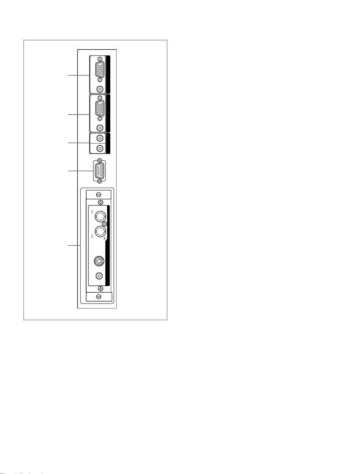
入出力端子パネル
1
2
3
4
RGB / YUV
AUDIO
RGB / YUV
AUDIO
IN OUT
INPUT 1
INPUT 2
CONTROL S
REMOTE
2 INPUT2(RGB/YUV信号入力)端子
RGB/YUV(RGB/YUV信号入力)端子(D-sub15ピン):
コンピューターや映像機器のアナログRGB信号出力端子ま
たはコ ンポーネント(YUV)信号出力端子と接続します。
また、 HDアナログコンポーネント(Y/P
B/PR)信号の入力に
も対応しています。コ ンポーネ ント信号を この端子へ入力す
る場合には、53(JP)ページのピン配列を参考にしてくださ
い。
AUDIO(音声入力)端子(ステ レオミニジ ャック):音声信号を
入力します。コンピューターや 映像機器の音声出力端子と接
続します。
3 CONTROLSIN/OUT(コントロールS信号入力/出
力)端子(ミニジャック)
ビデオ機器や他のディスプレイ のCONTROLS端子に接続する
と、 1台のリモートコマンダーで複数の機器を操作できます。本機
のCONTROLSOUT端子と他の機器のCONTROLSIN端子、
本機のCONTROLSIN端子と他の機器のCONTROLSOUT端
子を接続します。
IN OUT
COMPOSITE
VIDEO
5
Y/C IN AUDIO IN
1 INPUT1(RGB/YUV信号入力)端子
RGB/YUV(RGB/YUV信号入力)端子(D-sub15ピ ン):
コンピューターや映像機器のアナログRGB信号出力端子ま
たはコ ンポーネント(YUV)信号出力端子と接続します。
また、 HDアナログコンポーネント(Y/P
B/PR)信号の入力に
も対応しています。コ ンポーネント信号を この端子へ入力す
る場合には、53(JP)ページのピン配列を参考にしてくださ
い。
AUDIO(音声入力)端子(ステ レオミニジ ャック):音声信号を
入力します。コンピューターや映像機器の音声出力端子と接
続します。
4 REMOTE(RS-232C)用端子(D-sub9ピン)
RS-232Cプロトコルを使って、リモ ー トコン トロールを行う場合に接
続します。詳しく はお買い上げ店また は ソ ニーのサー ビス窓口にご
相談ください。
5 VIDEO(ビデオ)端子
COMPOSITEIN(映像入力)端子(BNC型):映像機器の
コンポジッ ト信号出力端子と接続します。
COMPOSITEOUT(映像出力)端子(BNC型):映像機器
のコ ンポジ ット信号入力端子と接続します。
Y/CIN(映像入力)端子(ミニDIN4ピン):映像機器のY/
C出力端子と接続します。
AUDIOIN(音声入力)端子(ス テレオミニジャック):音声信
号を入力します。映像機器の音声出力端子と接続します。
INPUT1またはINPUT2のRGB/YUV信号入力端子に接続する
ケーブルは、下記のフェライトコア付ケーブルか相当品を使用して
ください。
SMF-400(DSub-DSub15P)
MTSB-15HKBB-18(DSub15P-BNC)
11
(JP)
Page 12
各部の名称と働き
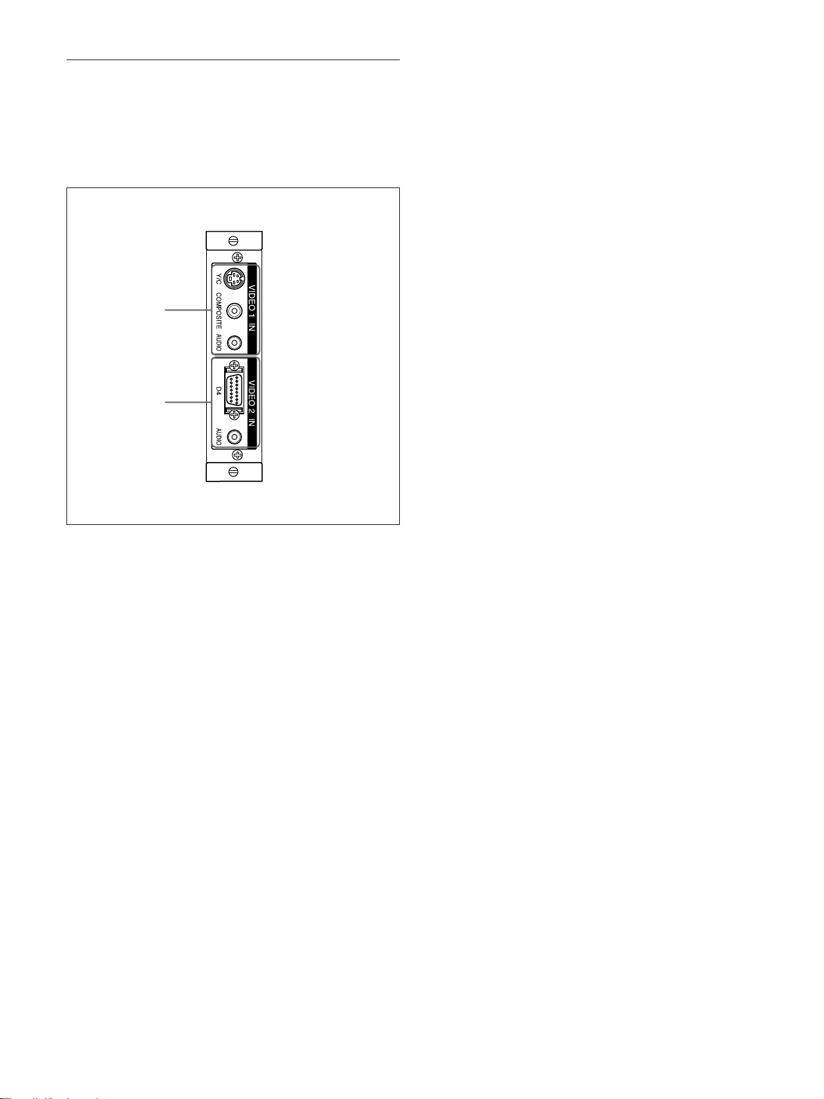
D4端子アダプターBKM-B11(別売り)
VIDEO端子部はスロットイン方式になっていて、別売りのD4端子
アダプターBKM-B11に付け換えることができます。
◆ BKM-B11の取り付けかたについては、お買い上げ店またはソニーの
サー ビス窓口にご相談ください。
1
2
1 VIDEO1IN(ビデオ1入力)端子
Y/C(映像入力)端子(ミニDIN4ピン):映像機器のY/C出
力端子と接続します。
COMPOSITE(映像入力)端子(ピンジャ ッ ク):映像機器の
コンポジッ ト信号出力端子と接続します。
AUDIO(音声入力)端子(ステ レオミニジ ャック):音声信号を
入力します。映像機器の音声出力端子と接続します。
2 VIDEO2IN(ビデオ2入力)端子
D4(映像入力)端子(D端子型):映像機器のD出力端子と
接続します。
AUDIO(音声入力)端子(ステ レオミニジ ャック):音声信号を
入力します。映像機器の音声出力端子と接続します。
12
(JP)
Page 13
各部の名称と働き
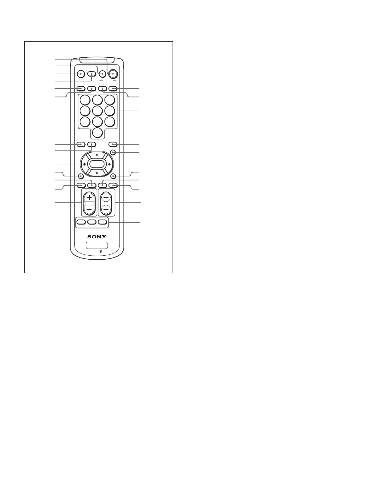
リモートコマンダーRM-971
1
2
3
4
5
6
7
8
9
0
qa
qs
qd
MUTING
DISPLAY STBY
INPUT 1 INPUT 2 VIDEO OPTION
POWER
123
456
7809
S/VIDEO ASPECT
RGB/YUV
ENTER
BRIGHT
H SHIFT V SHFT H SIZE
VOL CONTRAST
ON
MENU
CHROMA
VSIZE
qf
qg
qh
qj
qk
ql
w;
wa
ws
8 S/VIDEOボタン
標準装備またはオプションアダプターを装着 し た際の、VIDEO端
子からの入力信号を切り換えます。押すた びに、 COMPOSITE
INとY/CINの間で切り換わります。
M/m/</,/ENTER(エンター)ボタン
9
M/m/</,ボタンでメ ニュ ーの カーソル(黄色)を移動 させた
り、数 値などを設 定します。ENTERボタンを押すと、選んだメ
ニューや設定した内容を確定します。
q; BRIGHT(ブライトネス)ボタン
画質モードが「ユーザー1〜3」のと き、 画像のブライトネスを 調 整
します。 このボタン を押した後に M/mまたは </, ボタ ン9で
調整します。
qa VSHIFTボタン
垂直方向の画像位置を調整します。このボタ ンを押した後に、M/
mボタン9 で調整します。
qs HSHIFTボタン
水平方向の画像位置を調整します。このボタ ンを押した後に、M/
mまたは </,ボタ ン9 で調整します。
ID MODE
PFM
OFF
wd
RM-971
ON SET
1 POWER(電源)ONスイッチ
押すと電源が入ります。
2 STANDBYボタン
押すとスタンバイ状態になります。
3 MUTINGボタン
音を消します。
4 DISPLAYボタン
入力されている信号の種類および画質モードを画面に 表示しま
す。もう1度押すと表示は消え ます。 表示された状態でしばらく経
つと自動的に表示は消えます。
5 INPUT1ボタン
INPUT1端子に接続した機器からの入力信号を選びます。
6 INPUT2ボタン
INPUT2端子に接続した機器からの入力信号を選びます。
qd VOLUME+/−ボタン
音量を調整します。
qf OPTIONボタン
オプションアダプターを装着 し た際、そこに 接続した機器から の入力
信号を選びます。
qg VIDEOボタン
標準装備のVIDEO端子のCOMPOSITEIN端子またはY/CIN
端子に接続した機器からの入力信号を選びます。
qh 数字ボタン
インデックス ナ ンバーを入力するときに使用します。
qj ASPECTボタン
画面の横縦比(ズームモード)を選択 します。
qk MENU(メニュー)ボタン
画面にメニューを出すときに使用します。もう一度押すとメニュー
が消えます。
◆ MENUボタンをメニューの階層を戻すために使用する場合は、「初期
設定メニュー」(26(JP)ペ ージ ) をご覧ください。
ql CHROMAボタン
画質モードが 「ユーザー 1〜3」のとき、画像の色の濃さを調整し
ます。このボタ ンを押した後に、M/mまたは</,ボタ ン9で調
整します。
7 RGB/YUVボタン
INPUT1またはINPUT2端子に接続した機器の入力信号フォー
マットに合わせます 。押すたびに、RGBとYUVの間で切り換わり
ます。
w; HSIZEボタン
水平方向の画像の大きさを調整します。このボタ ンを押した後に、
M/mボタン9 で調整します。
(JP)
13
Page 14
各部の名称と働き
wa VSIZEボタン
垂直方向の画像の大きさを調整します。このボタ ンを押した後に、
M/mボタン9 で調整します。
ws CONTRAST(コントラスト)+/−ボタン
画質モードが 「ユーザー1 〜 3」のとき、画像のコントラス トを調整
します。
wd IDMODE(ON/SET/OFF)ボタン
ONボタンを押すとインデックス ナ ンバーが画面に表示されます。
数字ボタンqhで、操作したいディスプレイのイ ンデ ックスナンバー
を入力しSETボタンを押します。OFFボタンを押すと、IDモードを
抜けて通常の画面に戻ります。
◆インデッ ク ス ナ ンバーについて詳しくは、「特定のディスプレイ をリモート
コマンダーで操作する」(49(JP)ページ)をご覧く ださい。
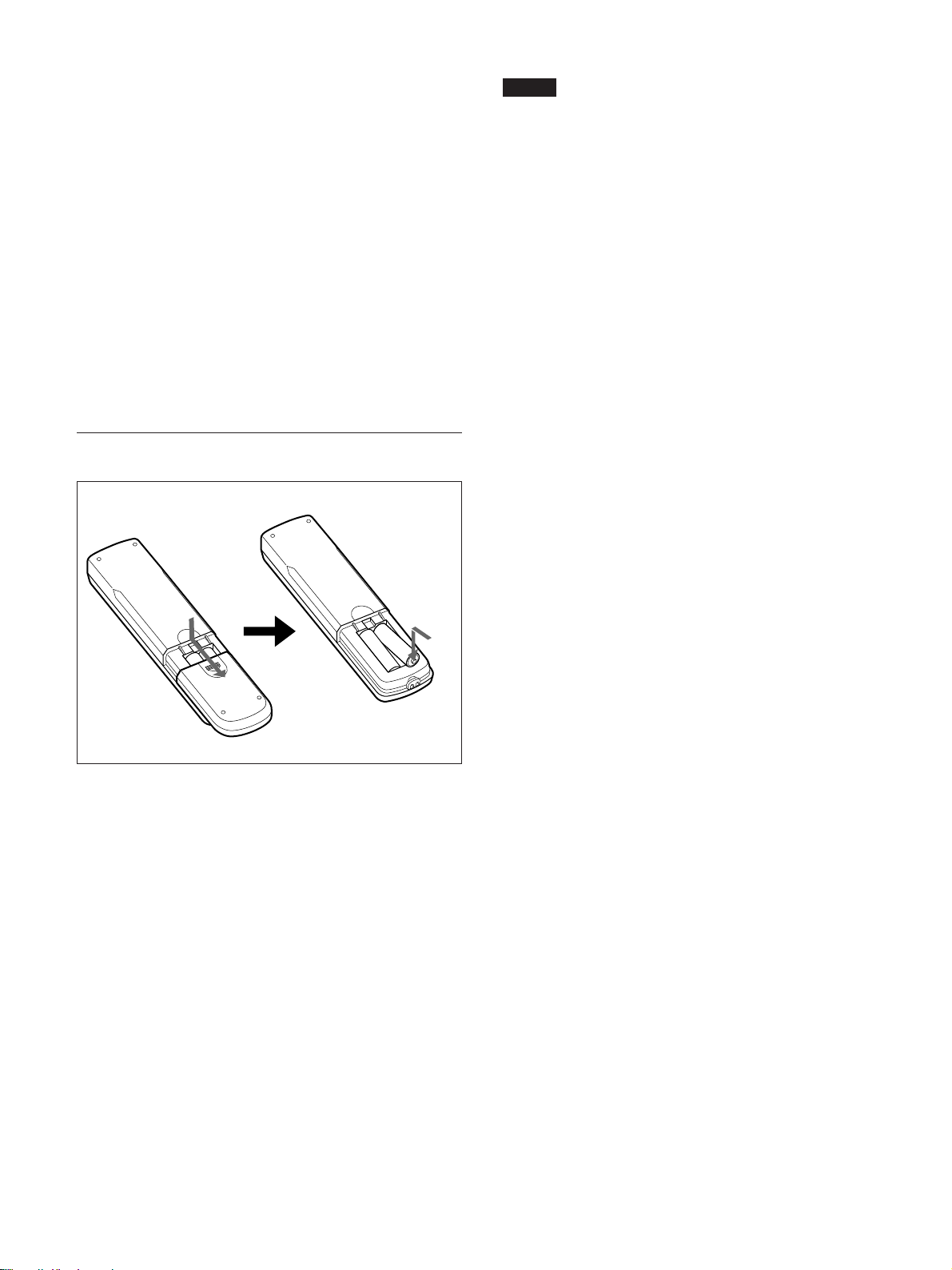
電池の入れかた
ご注意
・落と したり、踏みつけたり、中に液体をこ ぼしたりしないよ う 、て
いねいに扱って ください。
・直射日光が当たるところ、暖房器具のそばの温度が高いと ころ、
湿気が多いところには置かないでください。
・ディ スプレイ本体のリモ コン受光部に、直射日光や照明器具の強
い光が当たらないようにしてください。リモートコマンダーで操作
できな くなる場合があ ります。
・ディ スプレイ を操作するために必要なボタンがついていますの
で、 紛失 しないようにしてください。
単3形乾電池
2個
E
e
e
E
必ず#極側から電池を
入れてください。
電池の寿命は、通常の使用で約6か月です。リモー トコマン ダー
操作が効かなくなり始めたら寿命ですので、新しい電池とお取り
換え ください。
リモートコマンダーで操作できないときは
STANDBYインジケーターが点灯しているかどう か確認してくださ
い。また、リモー トコン トロール設定メニューの リモートモードが「切」
になっていないかどうか確認してください。ディ スプレイ 本体の電
源が入っているとき か 、スタンバイ状 態 のときで 、リモー トモードが
「TV」または 「PJ」のときのみリモートコマンダーで操作できます。
◆リモートモードについて詳しく は、「リモー トコントロー ル設定メニュー」
(27(JP)ページ)をご覧く ださい。
14
(JP)
Page 15
使用上のご注意
使用上のご注意
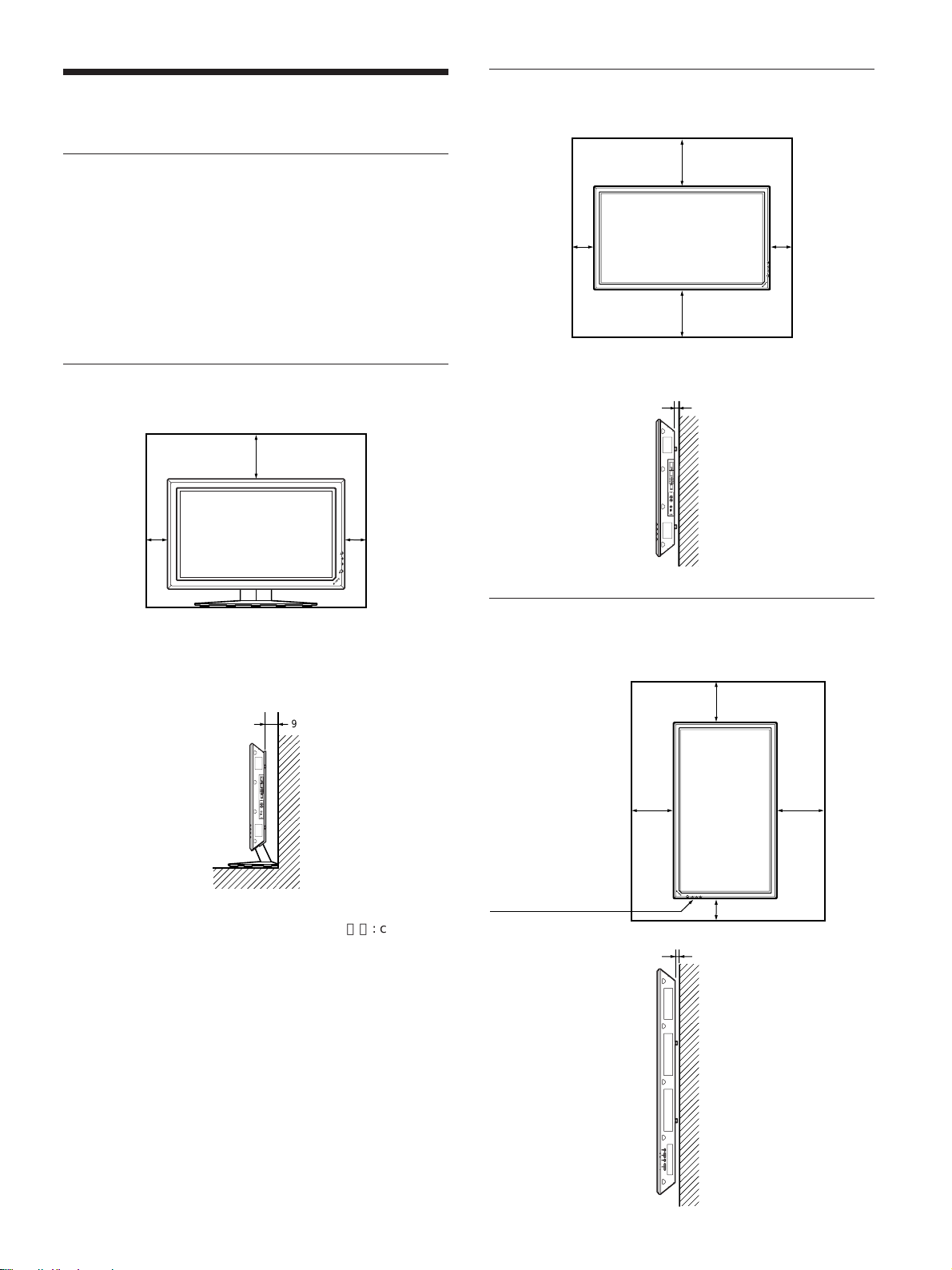
周囲に十分なスペースをとる
・内部の温度上昇を防 ぐためディスプレイの周 囲に以下に示す以
上の距離をあけてください(下図参照)。
・スタン ドには、専用スタンドSU-P50C(別売り)をご使用ください。
・通電中は高温になる部分があり、やけどの原因となり ます。通電
中やスタンバイにした 直後は、本機の上側、後側には手を触れ
ないでください。
スタンド(別売り)を使用する場合
前面
20
10
10
ON
NDBY
STA
水平方向で使用する場合
前面
10
側面
25
10
25
2.5
単位:cm
側面
垂直方向で使用する場合
前面
20
9
25
単位:cm
設置の際は、必ず
1(スタンバイ)
スイッチを下にし
てください。
側面
20
10
2.5
MENU ENTER VOLUME
単位:cm
(JP)
15
Page 16
使用上のご注意/接続
画面の焼き付きや残像についてのご注意
次の1〜5 のような画像を画面上に一定時間表示し続けると、
部分的に焼き付きや残像が発生することがあります 。これはプラズ
マディスプレイ パネルの特性上起こるものであり、以下のA〜D
の操作を行うことにより、焼き付きや残像を低減できます。
焼き付きや残像が発生しやすい状態
1 上下に帯が表示されるワイド映像 (レターボックス映像 )
2 画面横縦比4:3の映像
3 ゲー ム映像
4 DVDのメニュー画面
5 BSデジタル/デジタルCSチューナー、ビデオデッキなど
の映像に切り換えたときに表示されるチャンネ ル番号やメ
ニューなど
焼き付きや残像を低減させるために
A 画面の焼き 付きや残像を低減させるため、「スクリーンセー
バー」を使 うことをお勧めします。
B BSデジタル/デジタルCSチューナー、ビデオデッキなど
の映像に切り換えた ときに画面に表示 される チャンネ ル番
号やメニューなどは、BSデジタル /デジタル CSチュー
ナー、ビデオデッキ側の画面表示操作で表示を消すこと
をお勧めし ます。詳し くは、お使いのBSデジタル/デジタ
ルCSチューナー、ビデオデッキなどの取扱説明書をご覧
ください。
C 画面の「明るさ」を暗くして、画面モードを 「ワ イドズーム」
や「フル」 で表示すると、画面の焼き付きや残像が起こり
にく くなります。
D 画面の焼き付きや残像が軽度のときは、「スクリーンセー
バー」の「画像反転」機能を使って目立たなくすることが
でき ますが、一度起こった焼 き付きや残像は完全には消え
ません。
スクリーンセーバー(画像反転)についてのご注
意
接続
スピーカーの接続
別売りのスピーカー(SS-SP10A)を接続 して 、より臨場感あふれる
映像をお楽しみいただけます。ス ピーカーの接続について詳 しく
は、スピーカーに付属の取扱説明書をご覧の上、正しく接続して
ください。
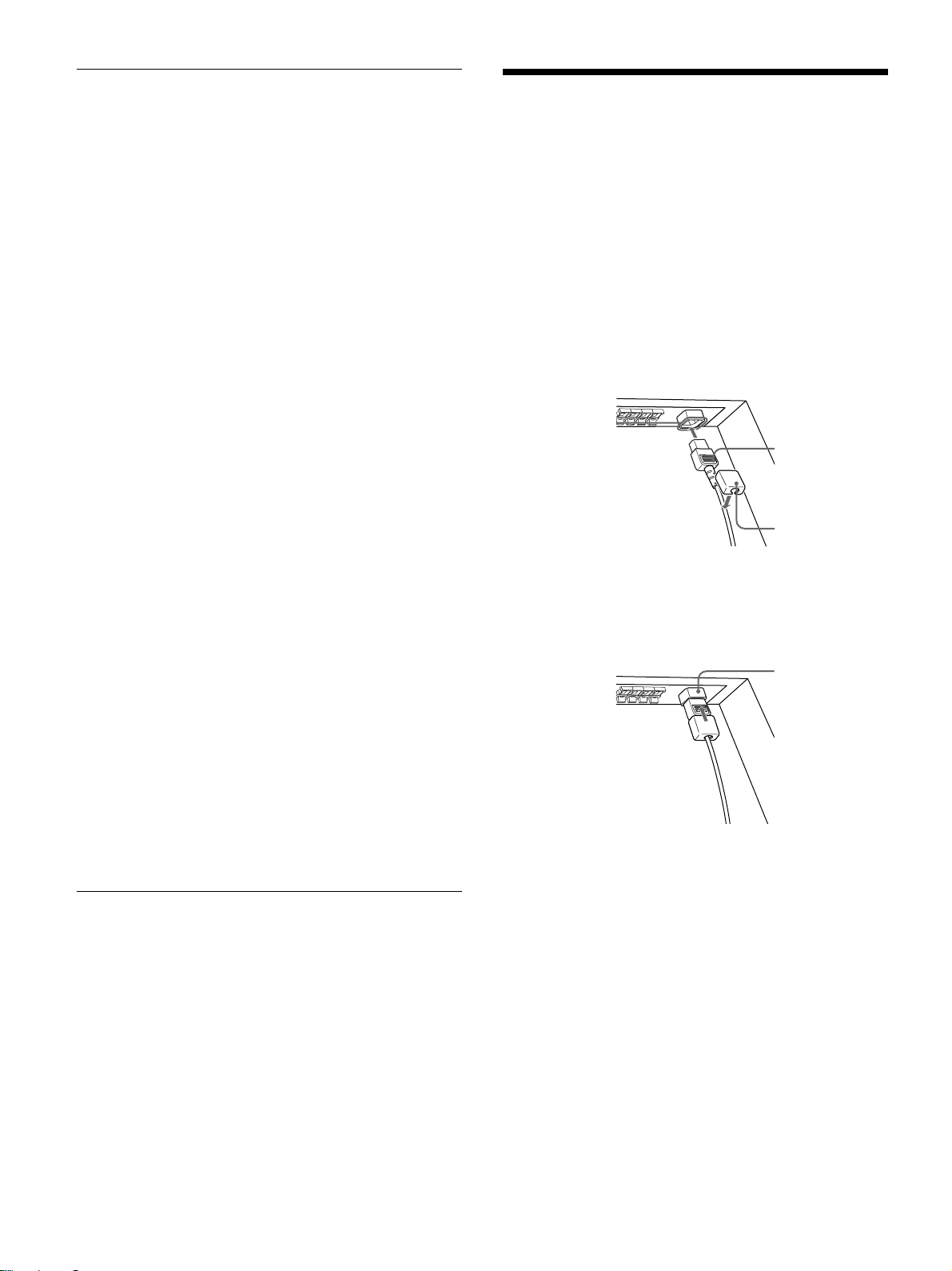
電源コードの接続
1 電源 コードを下面のACINソケットに差し 込 み 、 ACプラグホル
ダー(付属)を電源コードに取り付け る 。
ACINソケット
電源コード
ACプラグ
ホルダー
2 ACプラグホルダーをスライドさせて、本体側のACINソケッ
トカバ ーにはめ込む。
ACIN
ソケットカバー
電源コードをはずすには
ACプラグホルダーのつめを は さ み、ロックを 解 除し てからプラグを
つかみ、電源コ ードをはずしてください。
接続例
表示画面が写真のネガフィルムのようになった場合、「ス クリーン
セーバー」 の 「画像反転」が「自動」もしくは「入」に設定されて
いる可能性があります。通常の画像に戻すためには、「切」を選ぶ
か「自動」にて時刻の設定をしてください。
画像反転とは、焼き付いてしまった画像を表示したまま、画面の
色合いを反転し(例:白→黒、黒→白)補正します。画像反転中
は写真のネガフィルムのような画像になりますが、故障ではありま
せん。
(JP)
16
接続上のご注意
・各機器の電源を切ってから接続を行ってください。
・接続ケ ーブルはそれぞれの端子の形状 に 合っ た 正しいもの をお
選びください。
・プラグはしっかり 差し込んでください。接続が悪いとノイズの原
因とな り ます。
・コー ドを抜く ときは必ずプラグを持って抜いてください。
・接続の詳細については、各機器の取扱説明書をご覧ください。
・電源コードのプラ グは、ACINソケットに、まっすぐ 突 き当たるま
で差し込んでください。
・付属のACプラグホルダーは、使用する電源コードのプラ グが確
実に固定できる方を選んでお使いください。
Page 17
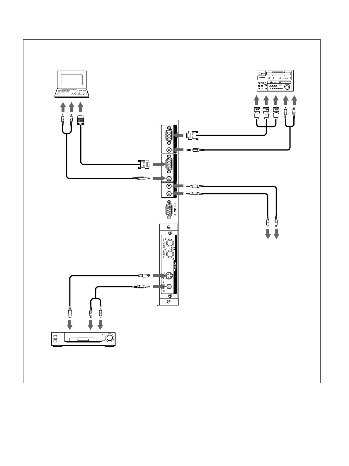
接続例
コンピューター
接続
ベータカムSPビデオ
カセットレコーダーなど
コンポーネント
信号出力へ
映像出力へ音声出力へ
RGB / YUV
RGB/YUVへ
INPUT 1
音声
出力へ
AUDIO
RGB/YUVへ
AUDIOへ
RGB / YUV
AUDIO
IN OUT
AUDIOへ
INPUT 2
CONTROLSINへ
CONTROL S
CONTROLSOUTへ
CONTROLS
入力端子へ
CONTROLS
出力端子へ
Y/CINまたは
COMPOSITE
INへ
AUDIOINへ
映像出力へ 音声出力へ
ビデオカセットレコーダー、
ゲーム機、DVDプレーヤーなど
17
(JP)
Page 18
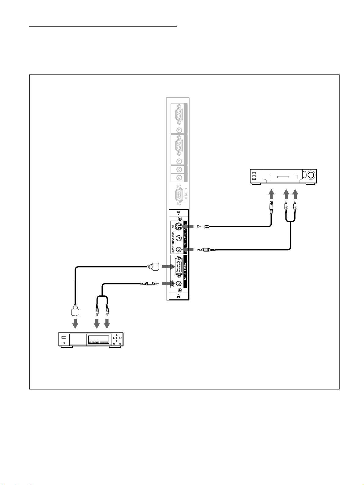
接続
D4端子アダプターBKM-B11(別売り)を装着
した場合の接続例
別売りの D4端子アダプターBKM-B11を取り付けた場合の接続
例は以下のとおりです。
RGB / YUV
AUDIO
RGB / YUV
INPUT 1
INPUT 2
D映像出力へ
音声出力へ
D4へ
AUDIOへ
AUDIO
IN OUT
CONTROL S
Y/Cまたは
COMPOSITEへ
AUDIOへ
ビデオカセットレコーダー、
ゲーム機など
映像
出力へ
音声出力へ
18
BSデジタルチューナー、
DVDプレーヤーなど
(JP)
Page 19
接続
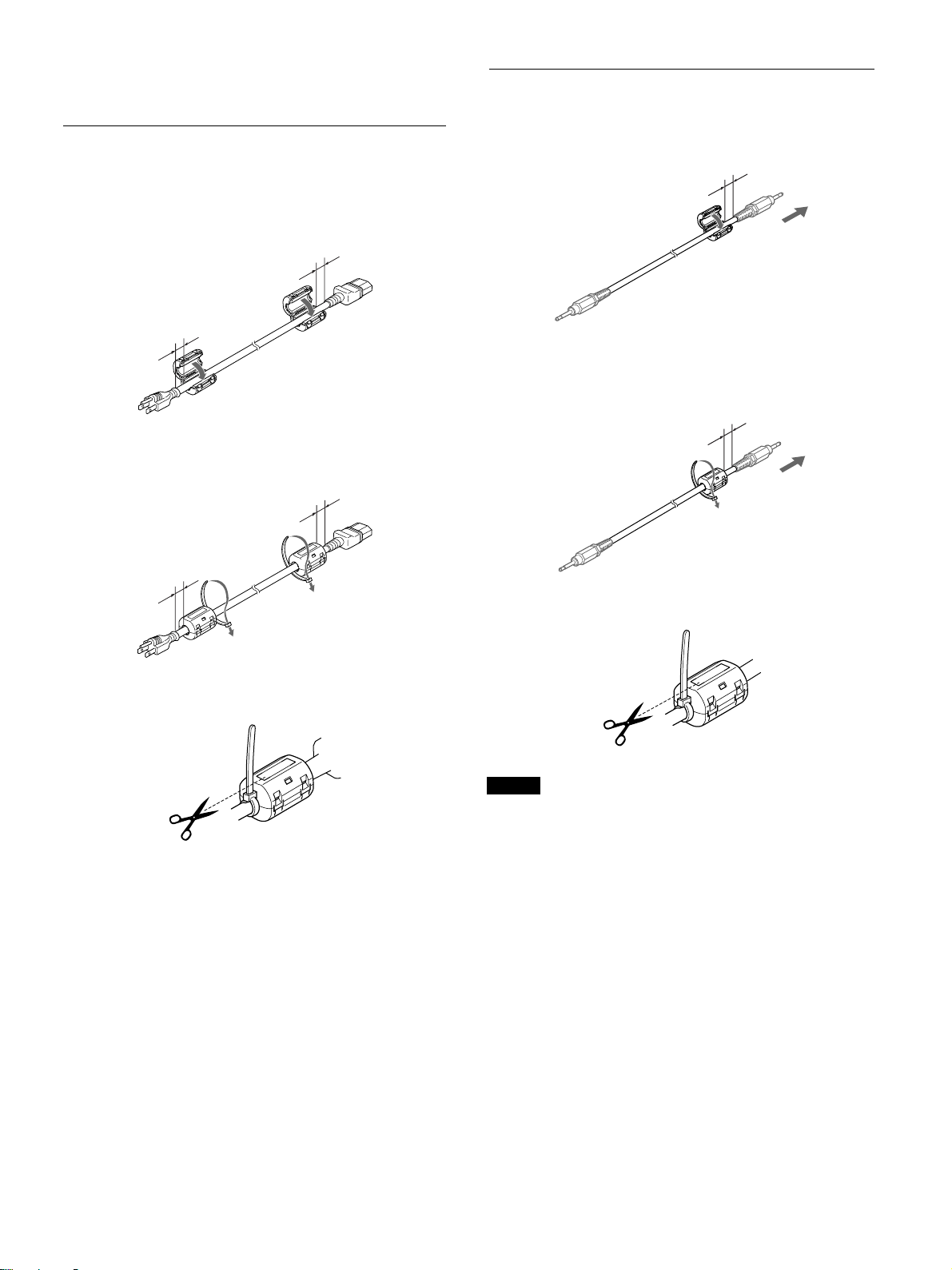
フェライトコアの取り付け
電源コードに取り付ける場合
1 電源 コードの両端にフ ェ ラ イトコアを取り付け、カチ ッ と音がす
るまでしっかりとしめる。
10mm以内
10mm以内
2 フェライトコアがず れないようにストッパーを巻き付ける。
10mm以内
ケーブルに取り付ける場合
1 ケー ブルの本体側にフェ ラ イトコアを取り付け、カチッ と音が
する まで しっかりとしめる。
10mm以内
2 フェライトコアがずれないようにストッパーを巻き付ける。
10mm以内
10mm以内
3 ストッパーを しっかり締め、 余分な部分を切り取る。
3 ストッパーを しっかり締め、 余分な部分を切り取る。
ご注意
・RGB/YUVで接続する際は、指定のケーブルをご使用ください。
SMF-400(D-Sub15P-5BNC)
SMF-410(D-Sub15P-D-Sub15P)
下記の端子にケーブルを接続する場合は、付属のフェライトコア
を取 り付けてご使用ください。
AUDIO(INPUT1)
AUDIO(INPUT2)
・本機は、接続ケーブルに フェライトコアを取り付けないと 、EMCの
基準をみたしませんので、ご注意ください。
19
(JP)
Page 20
接続
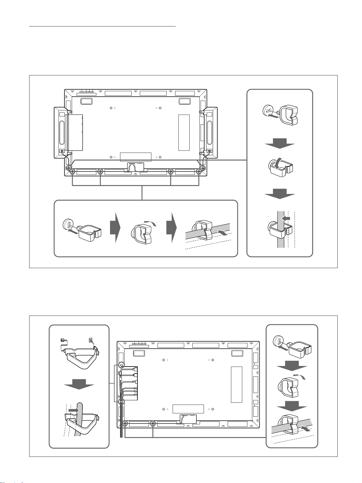
ケーブルホルダーを使う
付属のケーブルホルダーB(×6)を使って、スピ ーカーケーブ ル
をすっきりとまとめることが でき ます。ケーブルホルダーは、以下の
ように取り付けます。
本機後面
1
2
123
スピーカーを 使 用しない場合は、付属のケーブルホル ダーA(×2)
とケーブルホルダーB(×2)を使ってケーブル類をまとめることが
でき ます。ケーブルホルダーは図のよ う に取り付けます。
1
本機後面
3
1
2
20
2
3
(JP)
Page 21
メニューで行う調整と設定
メニューで行う調整と設定
4 M/mボタンで設定や調整値を選び、ENTERボタンを押す。
設定が決まり、元のメニューに戻ります。
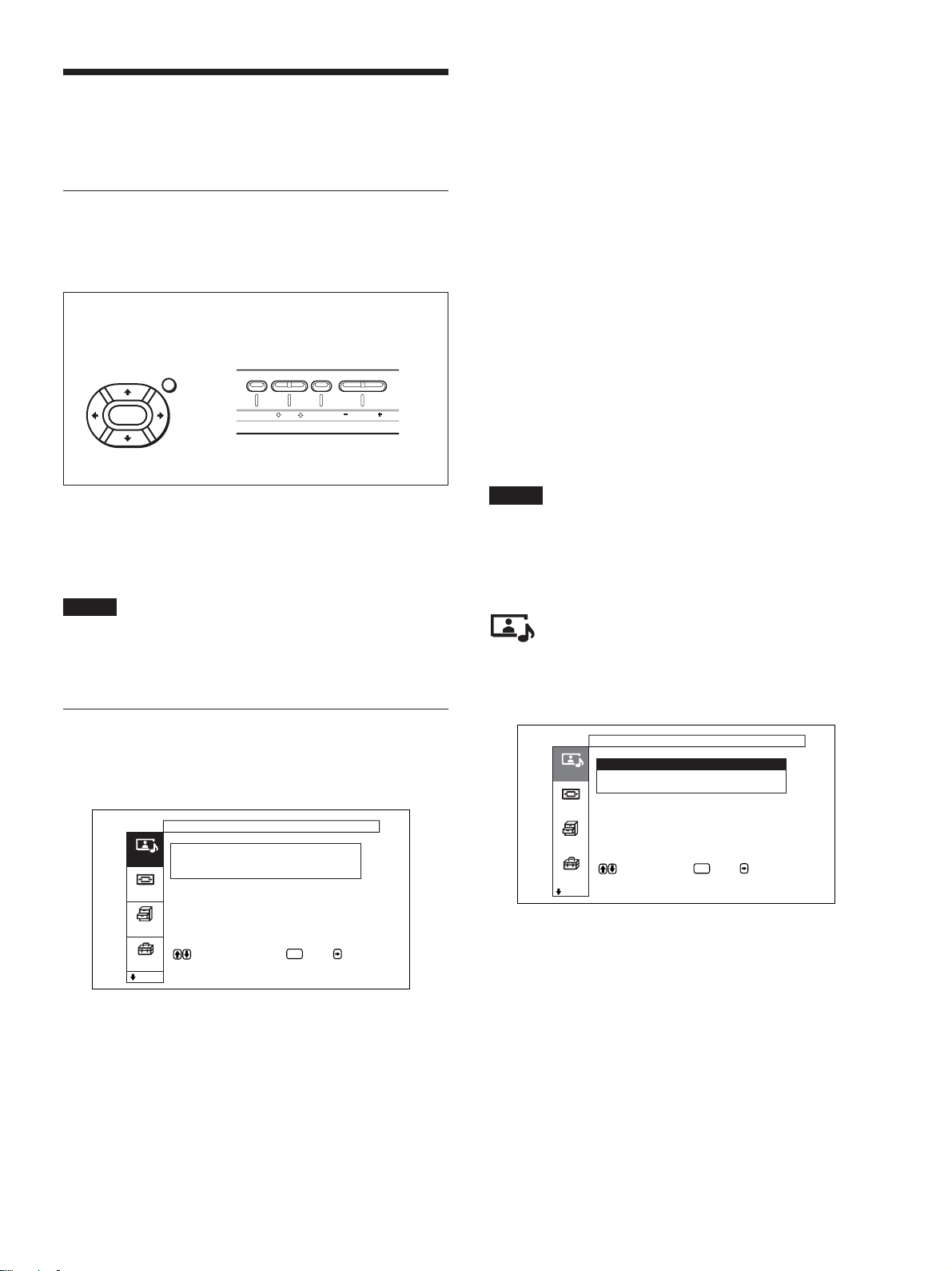
メニューの操作
メニュー操作ボタン
メニューは、リモー トコマン ダーまたはディスプレイ本体のコントロー
ルボタン部のメニュ ー 操作ボタンを使って操作します。
リモートコマンダー上
のメニュー操作ボタン
MENU
ENTER
ディスプレイのコントロールボタ
ン部のメニュー操作ボタン
MENU ENTER VOLUME
この取扱説明書ではリモートコマンダーを使って操作の説明を して
います。リモートコマンダーのM/mボタンおよびENTERボタンは
本体のM/mボタ ンおよびENTERボタンと、同じ働きをします。
ご注意
本体には</,ボタ ンがないため、一部操作が異なる部分があ
ります 。
メニューの操作方法
1 MENUボタンを押す。
メインメニューが表示されます。
画質 / 音質調整
画質モード : スタン ダード
画質調整
画質/音質
音質調整
画面モード
各種切換
で項目を選択します 。 または を押す
と調整メニューに入ります 。
初期設定
ENTER
2 M/mボタ ンでカー ソル(黄色)を動か して 、メインメニューを
決め、ENTERボタンを押す。
次のメニューにカーソルが移動します。
通常の画面に戻るには、MENUボタンを押します。
メニューの階層を移動するには、</,ボタ ンを使います。
◆ MENUボタンを階層の移動に使用したいときは、「メニュ ー キー 動作」
(26(JP)ページ)をご覧く ださい。
メニュー表示言語を切り換えるには
メニュー画面やメッセージの表示言語を6か国語の中からお好き
な言語に切り 換えることができます。
工場出荷時は「ENGLISH」(英語)に設定されています。
表示言語の切り換 えについて詳しくは、「メニ ュ ー表示の言語を選
ぶ」(43(JP)ページ)をご覧く ださい。
メニューの説明
ご注意
入力信号によって設定や調整ができない項目は背景が濃いグ
レーになります。また、 画面下部には「調整できません」と表示さ
れます。
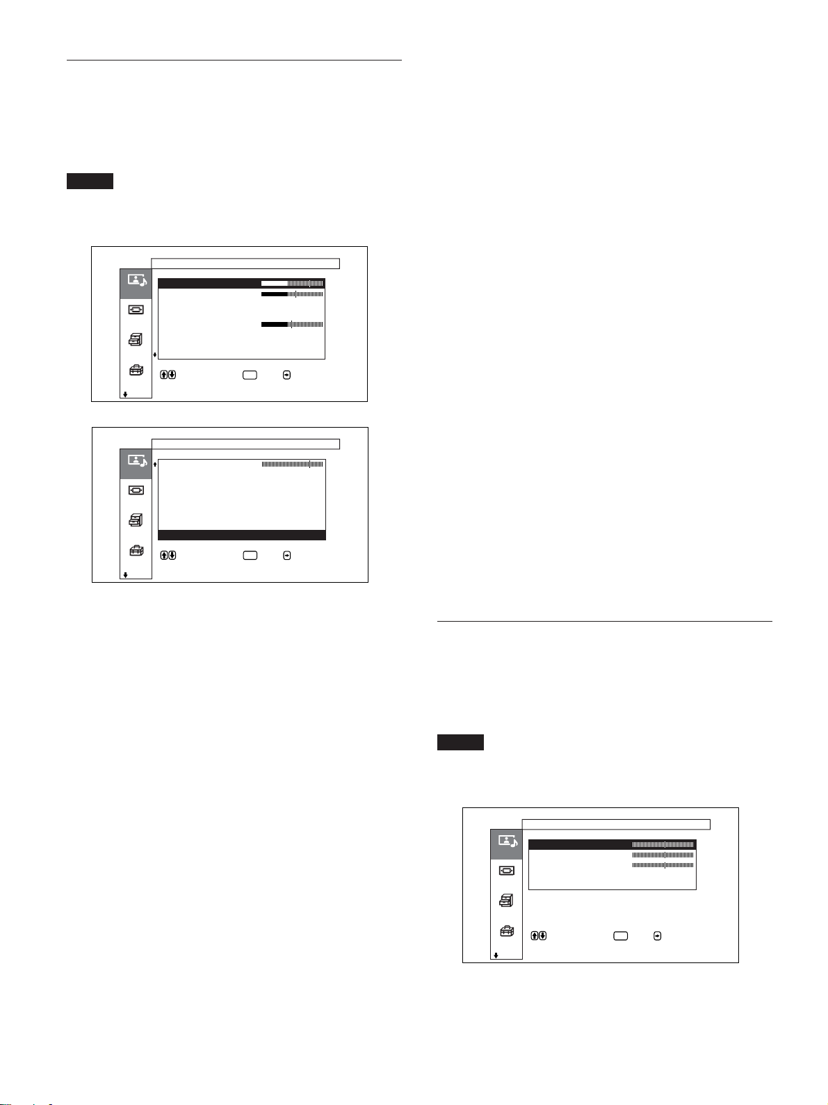
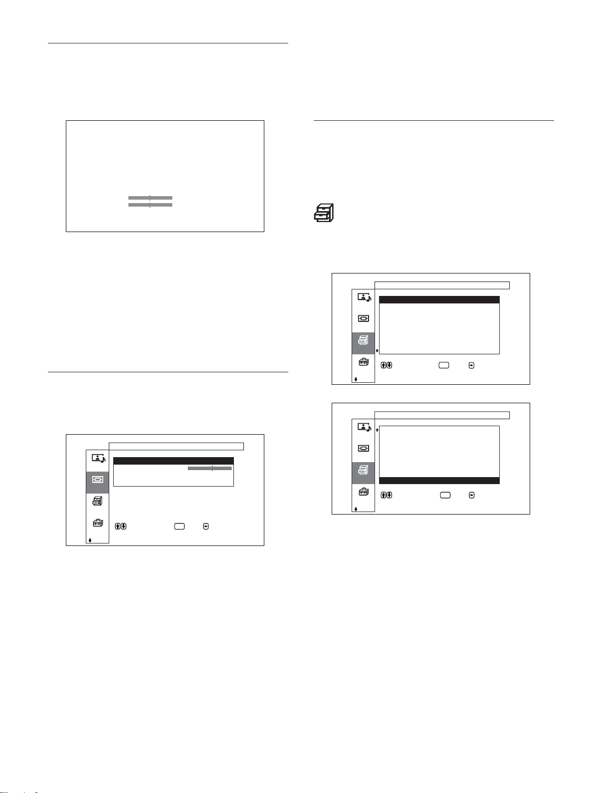
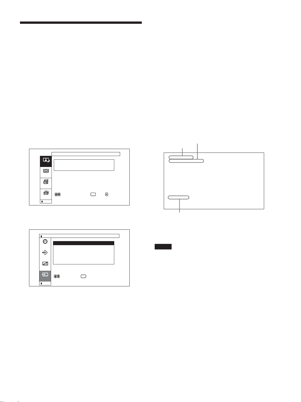
画質/音質調整メニュー
ディ スプレイに表示 される 映像の 画質と音質を調整するメニューで
す。
画質 / 音質調整
画質モード : スタン ダード
画質調整
画質/音質
音質調整
画面モード
各種切換
で項目を選択し、 または で決定しま
す 。
初期設定
画質モード
周囲の明るさや絵柄に合った画質モードを設 定します。
◆画質モードについて詳 しくは、「画質を選ぶ」(33(JP)ページ)をご覧く
ださい。
ENTER
3 M/mボタ ンでカー ソル (黄色)を動かして、設定する項目を
決め、ENTERボタンを押す。
それぞれの項目の設定画面が表示されます。
さらに次のメニューが表示された場 合は、 同様に設定する項
目を選びます。
21
(JP)
Page 22
メニューで行う調整と設定
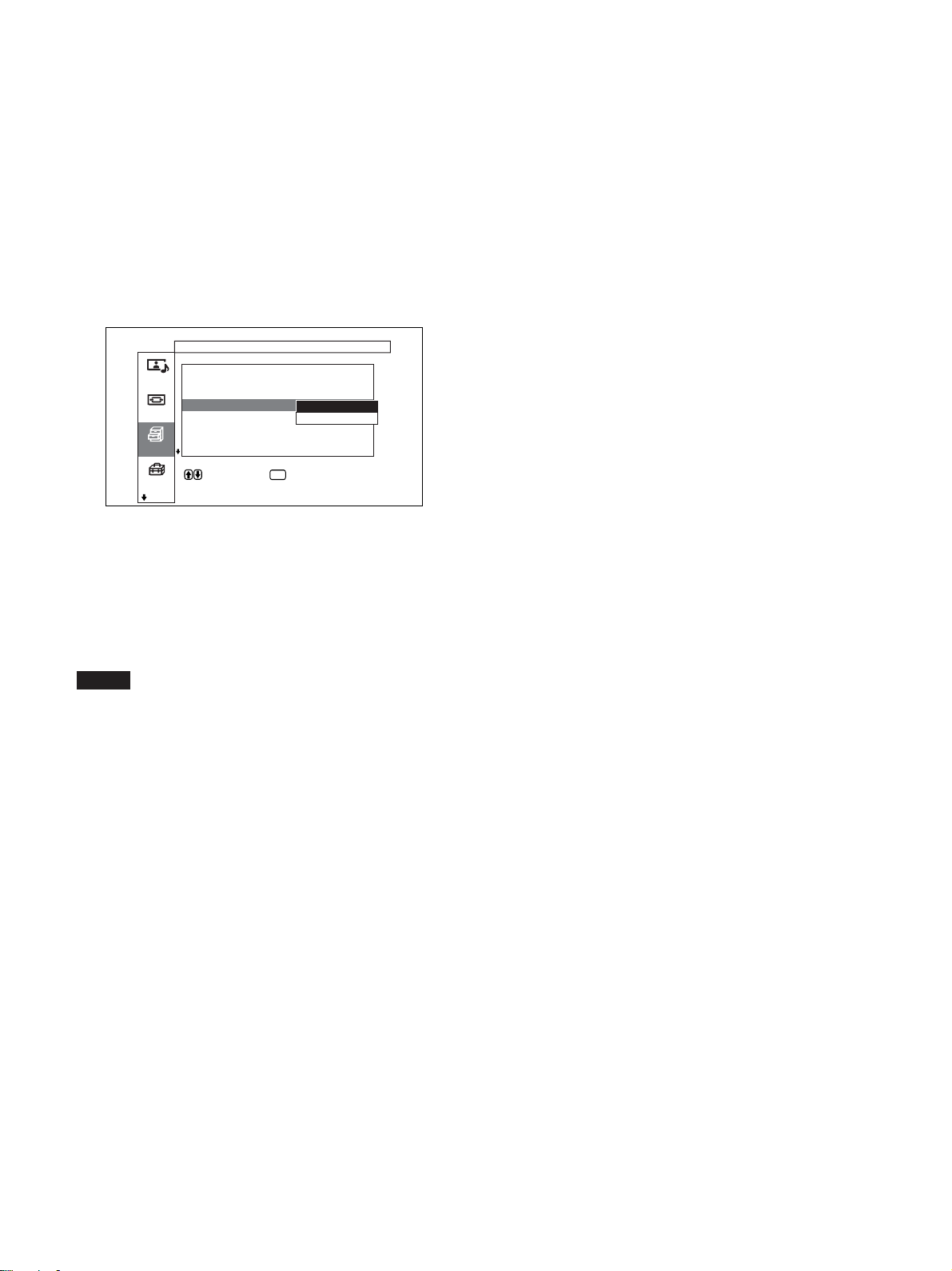
画質調整メニュー
画像を信号処理により調整するメニューです。
画質モードが「ユーザー1〜3」のとき 、 お好みの画質に調整する
ことが できます 。
ご注意
画質モードが「スタンダード」「ダイナ ミック」 のときは調整できませ
ん。
画質 / 音質調整
画質調整( ユーザー1 )
コントラスト
明るさ
画質/音質
色の濃さ
色あい
シャープネス
画面モード
NR : 切
シネマドライブ :
ダイナミックピクチャー:
各種切換
で項目を選択し、 または で決定しま
す 。
初期設定
画質 / 音質調整
画質調整( ユーザー1)
シャープネス
NR : 切
画質/音質
シネマドライブ :
ダイナ ミックピクチャ ー :
色温度 : 高
画面モード
色補正 :
ガンマ補 正 : 低
標準
各種切換
で項目を選択し 、 または で決定しま
す。
初期設定
ENTER
ENTER
シネマドライブ
自動にすると、フィルム映像特有の滑ら かな動き のあ る 映像を再現
します。
◆シネマドライブについ て詳しくは、「シネマドライブ」(34(JP)ページ)を
ご覧ください。
ダイナミックピクチャー
白をよ り 白 く、黒をより黒く してコントラストを強めます。
◆ダイナミックピクチャーについて詳しくは、「ダイナミックピクチャー」(34
(JP)ページ)をご覧く ださい。
色温度
色温度を調節します。
◆色温度について詳しくは、「色温度」(35(JP)ペー ジ)をご覧く ださい。
色補正
入にすると、美しく 健康的な色を再 現します。
◆色補正について詳しくは、「色補正」(36(JP)ページ)をご覧く ださい。
ガンマ補正
映像の明暗部分のバランスを「高」「中」「低」の3段階で設定し
ます。
◆ガンマ補正について詳しくは、「ガン マ補正」(36(JP)ページ)をご覧く
ださい。
標準
画質調整メニューの調整値を出荷時の値に戻します。
◆標準機能について詳しくは、「調整した画質を出荷時の設 定値に戻す」
(36(JP)ペ ージ)をご覧く ださい。
コントラスト
M/,を押すとコ ントラス トが強くなり、m/<を押すと弱 くなります。
明るさ
M/,を押すと画面が明るくなり、 m/<を押すと 暗くなります。
色の濃さ
M/,を押すと 画像の色が濃くなり、m/<を押すと 薄くなります。
色あい
M/,を押す と 画像が緑がかり、m/<を押すと赤みがかります。
シャープネス
M/,を押すと映像の輪郭補正レベル が強くなり、m/<を押す と
弱く なります。
NR
映像のざらつきや色ノイズを軽減するレ ベ ルを「 切 」「弱」「中」
「強」の4段階で設定します。
◆NRについて詳し くは、「NR(ノイズリダクション)」(34(JP)ページ)をご
覧く ださい。
音質調整メニュー
音質を信号処理により調整するメニューです。
画質モードが「ユーザー1〜3」のとき 、 お好みの音質に調整する
ことが できます 。
ご注意
画質モードが「スタンダード」「ダイナ ミック」のとき は調整できませ
ん。
画質 / 音質調整
音質調整( ユーザー1 )
高音
低音
画質/音質
バランス
サラウンド : 切
標準
画面モード
標準
各種切換
で項目を選択し、 または で決定しま
す 。
初期設定
高音
M/,を押すと高音が強くなり、 m/<を押すと 弱くなります。
ENTER
22
低音
M/,を押すと低音が強くなり、 m/<を押すと 弱くなります。
(JP)
Page 23
メニューで行う調整と設定
初期設定
バランス
M/,を押すと右側の音が強く なり、 m/<を押すと左側の音が
強く なります。
サラウンド
サラウ ンド機能を「切」「ホール」「シ ミュレー ト」の3段階で設定し
ます。
◆サラウンドについて詳し くは、「サ ラウンド」(41(JP)ページ)をご 覧く だ
さい。
標準
音質調整メニューの調整値を出荷時の値に戻します。
◆標準機能について詳しくは、「調整した音質を出荷時の設定に戻す」
(41(JP)ページ)をご覧く ださい。
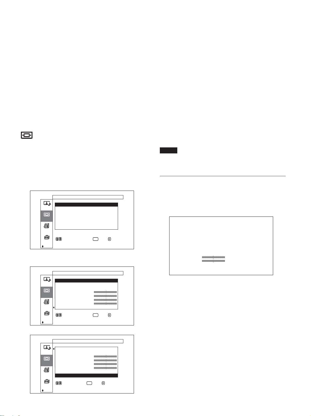
画面モード調整メニュー
画像のサイズや位置を調整するメニューです。
画面モード調整メ ニュー は、メニューキー動作の設定によって画
面およ び操作方法が異なります。
オートワイド設定
オートワイ ド機能を設定するメ ニューです。オートワイ ド機能とは、
通常のテレビ放送やワイドクリアビジョン、ワイドスクリ ーン画像な
ど、横縦比の異なる映像の種 類に対して最適 なワ イド切換を選び、
横縦比16:9のワイド画面いっぱいに自動的に画像を拡大する機能
です。
◆オートワイドについて詳 しくは、「オートワイドを設定する」(37(JP)ペー
ジ)をご覧く ださい。
ワイド切換
映像のサイズや種類に合わせてワイド表示を切 り 換えます。
◆ワイド切換について詳しく は、「ワイド切換を設定する」(38(JP)ページ)
をご覧く ださい。
ズームサイズ
画像を2倍、3倍、4倍に拡大します。
ご注意
ワイド切換が 「フル」に設定されているときのみ拡大できます。
メニューキー動作が「入/切」の場合(出荷時)
画面モード調整
オートワイド設定
ワイド切換 : ノーマル
画質/音質
ズームサイズ :
画像サイズ
画像位置
画面モード
ドット調整
標準
各種切換
で項目を選択します 。 または を押す
と設定メニューに入ります 。
初期設定
ENTER
メニューキー動作が「戻る」の場合
画面モード調整
オートワイド設定
ワイド切替 : ノーマル
画質/音質
ズームサイズ:
水平サイズ
垂直サイズ
画面モード
水平位置
垂直位置
ドット調整
各種切換
で項目を選択します。 または を押す
と設定メニュー に入 り ま す。
初期設定
ENTER
画像サイズメニュー
画像のサイズを調整するメニューです。
この画面はメ ニュ ー キ ー動作が「入/切」に設定されているときの
み表示されます。
水平サイズ 00
垂直サイズ 00
初期設定
水平サイズ
水平方向に画像の大きさを調整します。,を押すと大きくなり、
<を押すと小さくなります。
垂直サイズ
垂直方向に画像の 大きさを 調 整します 。 Mを押すと大き くなり、 mを
押すと小さくなります。
画面モード調整
ワイド切替: ノーマル
ズームサイズ :
画質/音質
水平サイズ
垂直サイズ
水平位置
画面モード
垂直位置
ドット調整
標準
各種切換
で項目を選択し 、 または で決定しま
す。
初期設定
ENTER
23
(JP)
Page 24
メニューで行う調整と設定
初期設定
画像位置メニュー
画像の位置を調整するメニューです。
この画面はメ ニュ ー キ ー動作が「入/切」に設定されているときの
み表示されます。
水平位置 00
垂直位置 00
初期設定
水平位置
水平方向に画像の位置を調整します。,を押すと右に移動し、
<を押すと左に移動します。
垂直位置
垂直方向に画像の位置を調整します。Mを押す と 上に移動し、m
を押すと 下に移動します。
ドット調整メニュー
標準
ドッ ト調 整メ ニュ ーの調整値を出荷時の値に戻します。
◆標準機能について詳しくは、「ドッ ト調整項目を出荷時の設定に戻すに
は」(40(JP)ページ)をご覧ください。
標準
画面モ ードメニューのすべての調整値を 出荷時の値に戻します。
◆ 標準機能について詳しくは、「設定した画面 モードメニューの調整値を
出荷時の設定値に戻す」(40(JP)ページ)をご覧く ださい。
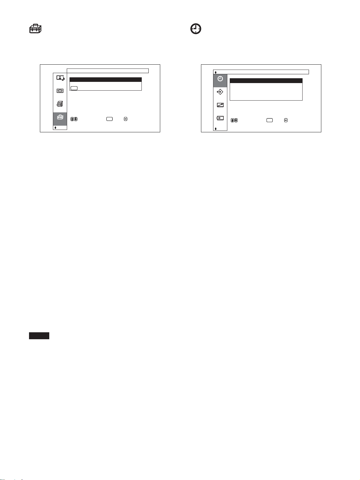
各種切換メニュー
消費電力を減らしたり、スクリーンセーバーを設定したりするメ
ニューです。
各種切換
消費電力 : 標準
スピーカー出力 : 入
画質/音質
クローズドキャプション:切
ステータス表示 : 入
スクリーンセーバー
画面モード
カラーマトリクス
HDモード :
RGBモード : PC
各種切換
で項目を選択し 、 または で決定しま
す 。
初期設定
ENTER
画像のドッ トを調整するメニューです。
コンピューターの信号を受信しているときのみ調整できます。
画面モード調整
ドット調整
自動調整
ドット位相
画質/音質
水平総ドット数 : 1344
標準
画面モード
各種切換
で項目を選択し、 または で決定しま
す 。
初期設定
ENTER
自動調整
ドッ ト位 相と水平総ドッ ト数を自動的に調整します。
◆自動調整について詳しくは、「ドッ ト位 相を 調整する」(40(JP)ページ)
をご覧く ださい。
ドット位相
ドッ ト位相を調整します。M/,を押すと 大きくなり、m/<を押す と
小さ くなります。
水平総ドット数
水平方向の総ドッ ト数を 調整します。 M/,を押すと 大 きくなり、 m/
<を押すと小さくなります。
(JP)
24
各種切換
スピーカー出力 : 入
クローズドキャプション: 切
画質/音質
ステータス表示 : 入
スクリーンセーバー
カラーマトリクス
画面モード
HDモード :
RGBモード : PC
同期モード : 同期信号
同期モード : 同期信号
各種切換
で項目を選択し、 または で決定しま
す 。
初期設定
ENTER
消費電力
節電しながら画面を表示することができます。
◆消費電力について詳し くは、「節電モード機能」(32(JP)ページ)をご覧
ください。
スピーカー出力
入にすると、ス ピー カ ー(SS-SP10A、別売り)から音が出ます。
クローズドキャプション
字幕を画面に表示したいときに使用します。
◆クローズドキャプションについて詳しくは、「字幕を表示させる」(32(JP)
ペー ジ)をご覧く ださい。
ステータス表示
入にすると、ディスプレイ の電源投入時や入力信号が切り換わっ
たとき 、入力されている信号の種類と画質モードを約5秒間画面
下部に表示します。
Page 25
メニューで行う調整と設定
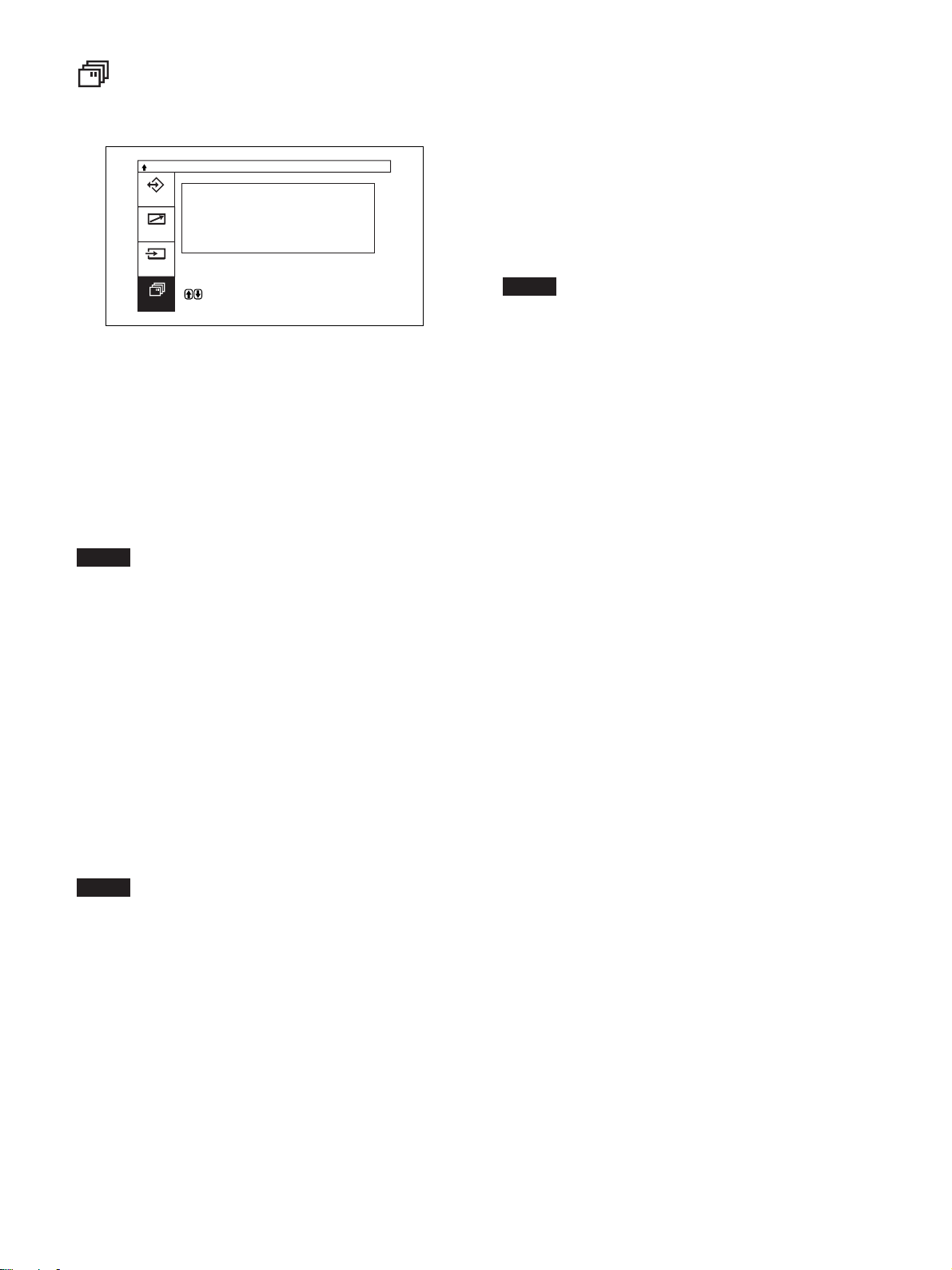
スクリーンセーバーメニュー
長時間にわ たっ て 同じ画面 を映したりする場合に生じる画面の焼
きつきや残像を補正したり軽減するときに使用します。
各種切換
スクリーンセーバー
画像反転 : 切
自動表示位置移動
画質/音質
画面モード
各種切換
で項目を選択し、 または で決定しま
す 。
初期設定
画像反転
画像の色あいを反転させるスクリーンセーバーを設定します。
◆ 画像反転について詳しくは、「ス クリー ンセーバー 機能」(44(JP)ペー
ジ)をご覧く ださい。
自動表示位置移動
一定の時間が た つと画像の 表示位 置 が自動的に移動す るスクリー
ンセーバーを設定します。
◆自動表示位置移動について詳しくは、「スクリーンセ ーバ ー機 能 」(44
(JP)ページ)をご覧く ださい。
ENTER
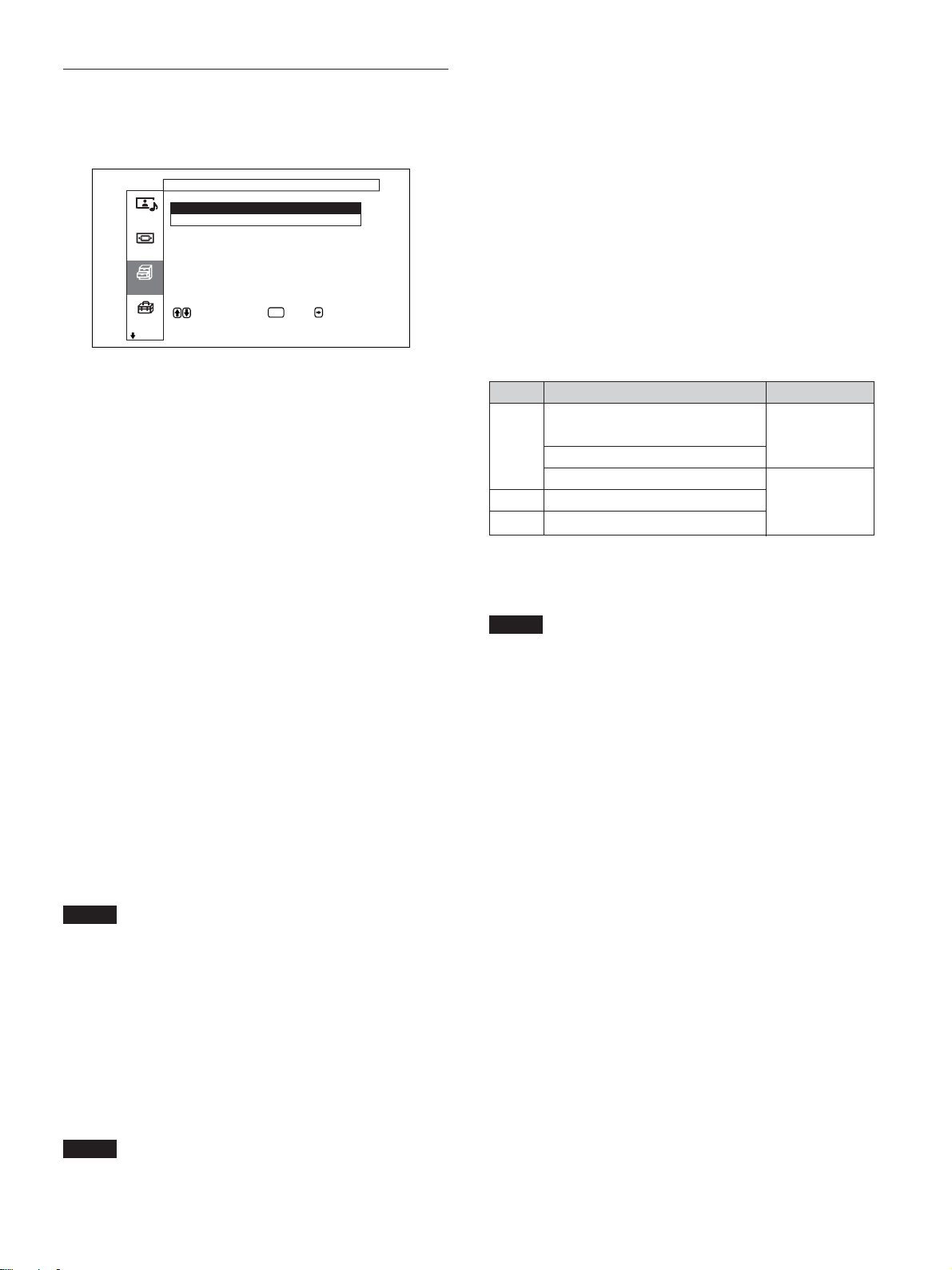
同期モード
INPUT1、INPUT2のRGB/YUV端子の13番ピンに入力される信
号によって、 モードを設定します。設定 でき る信号は、575/50i、
480/60iのみです。
同期信号:水平信号またはコンポジット同期信号*が入力される
場合
映像信号:映像信号またはコンポジット同期信号*が入力される
場合
*コンポジット同期の信号レベル によっては正しく画像が表示され
ない場合があります。その際は、同期モードの設定を変更して
ください。
入力信号と同期モードの設定
PIN D-sub入力信号 同期モード選択
480/60i、575/50iの
13
CompositeVideo 映像信号
CompositeSync
CompositeSync
13/14 HSync/VSync 同期信号
2 SyncOnGreen
◆ INPUT1、INPUT2のRGB/YUV端子のピン配列については、「ピン配
列」(53(JP)ページ)をご覧ください。
カラーマトリクス
接続している機器から のコ ンポーネ ント信 号 入力時の映像が自然
な色あいになる よう に設定 します。
◆カラーマトリクスについて詳しくは、「カラーマトリクスを 調整する」(45
(JP)ページ)をご 覧く ださ い。
HDモード
INPUT1、INPUT2またはオプションアダプターの D端子に入力さ
れるHDアナログコ ンポーネント信号によって モー ドを設定します。
1080i:BSデジタルチューナーを接続 している場合
1035i:ハイビジ ョンビデオデッキ (ベースバンド)など従来の
ハイビジョン機器を接続 してい る場合
ご注意
・オプシ ョンボードの設定を行うことは できません。
・BKM-B11のD4端子は、「1080i」で設定されています。
RGBモード
INPUT1、INPUT2のRGB/YUV端子に、RGB信号を出力する機
器を接続している ときに、モードを設定します。
DTV:RGB信号のデジタルチューナーなどを接続している場合
PC:パソ コ ンを接続している場合
ご注意
・「同期信号」に設定したときにコンポジットシンクを入力しても画
像が表示されない場合があり ます。その際は、同期モードの設定
を変更してください。
・同期モードの設定は、INPUT1、INPUT2で独立して設定できま
すが、信号設定の異なった入力信号に切り換えると、信号が出
なく なることがあ ります。 その場合は、入力信号に合った同期
モードの設定を入力端子ごとに行い 、入力端子を切り換えるよう
にしてください。
・「同期信号」しか選べない入力があります。この場合は13ピンに
「映像信号」を入力して も 画像は表示されません。水平・垂直同
期信号を13、14ピンに入力するか、SyncOnGreen信号をRGB
に入力してください。
・SyncOnGreenのときは同期信号に設定しないと画像が表示さ
れません。
・オプシ ョンボードでは、 同期モードの設定はできません。
・本機はコンポジットシンクおよび576/60Pの3値シンクには対応
していま せん。
ご注意
・オプシ ョンボードの設定を行うことは できません。
25
(JP)
Page 26
メニューで行う調整と設定
初期設定メニュー
メニュー表示の言語や映像ソースを選んだり、メニューキーの機
能を設定した りするメニューです。
初期設定
言語 : 日本語
カラー方式 :
画質/音質
MENU
キー動作 : 入 /切
画面モード
各種切換
で項目を選択し、 または で決定しま
す 。
初期設定
言語
メニューに表 示する言語を日本語、英語、ドイ ツ語、 フ ランス語、
スペイン語、 イタリア 語 から選 び ます 。
◆言語について詳 しくは、「メニ ュ ー表示の言語を選ぶ」(43(JP)ペー
ジ)をご覧く ださい。
カラー方式
映像ソースを選びます。
自動:NTSC/PAL/SECAM/NTSC4.43またはNTSC/PAL-M/
PAL-Nの映像を見る場合
NTSC:NTSCの映像を見る場合
NTSC4.43:NTSC4.43の映像を見る場合
PAL:PALの映像を見る場合
SECAM:SECAMの映像を見る場合
PAL-M:PAL-Mの映像を見る場合
PAL-N:PAL-Nの映像を見る場合
PAL60:PAL60の映像を見る場合
カラー方式が「自動」に設定されている 場合 、下の階層でさらに
自動検出できるカラー方式を設定します。
・NTSC/PAL/SECAM/NTSC4.43を自動検出
・NTSC/PAL-M/PAL-Nを自動検出
ご注意
ビデオ受信時以外は設定できません。
ENTER
タイマー/時計設定メニュー
時刻やタイマーを設定したり 、 時刻を表示させたり、自動的に電源
が入ったり切れたりするように設定するメニューです。
タイマー / 時計設定
スリープ : 切
時刻設定
タイマー
時計表示 : 切
電源タイマー : 切
パワーセービング : 切
メモリー
リモー ト
で項目を選択し 、 または で決定し ま
す 。
入力切換
スリープ
設定した 時間 が過ぎると自動的に電源が切れます。設定できる時
間は30分、60分、90分、120分です。
◆スリープ につ い て詳しくは、「スリープ 機能」(46(JP)ページ)をご覧く
ださい。
時刻設定
時刻を設定するときに使用します。
◆時刻設定について詳し くは、「時刻を 設定する」(47(JP)ペー ジ)をご
覧く ださい。
時計表示
入にすると画面に設定 した時刻が表示されます。
◆時計表示について詳し くは、「時計を 表示する」(47(JP)ペー ジ)をご
覧く ださい。
電源タイマー
時間を自由に設定して、自動的に電源をオン/オフするようにし
ます。
◆電源タ イマーについて詳しくは、「電源タイマー機能」(47(JP)ページ)
をご覧く ださい。
パワーセービング
本機に信号が入力 されない状態が続くと、電源を自動的に切るよ
うにします。
◆パワーセービングについて詳し く は、「パワーセービング機能」(48(JP)
ペー ジ)をご覧く ださい。
ENTER
メニューキー動作
メニューキーを押 したと きの動作を選びます。
入/切:メニューキーを押すたびに、メニューの表示/消去を
繰り返します。
戻る : メニューキーを押すと、 カ ー ソルが前の階層に戻ります。
(JP)
26
Page 27
メニューで行う調整と設定
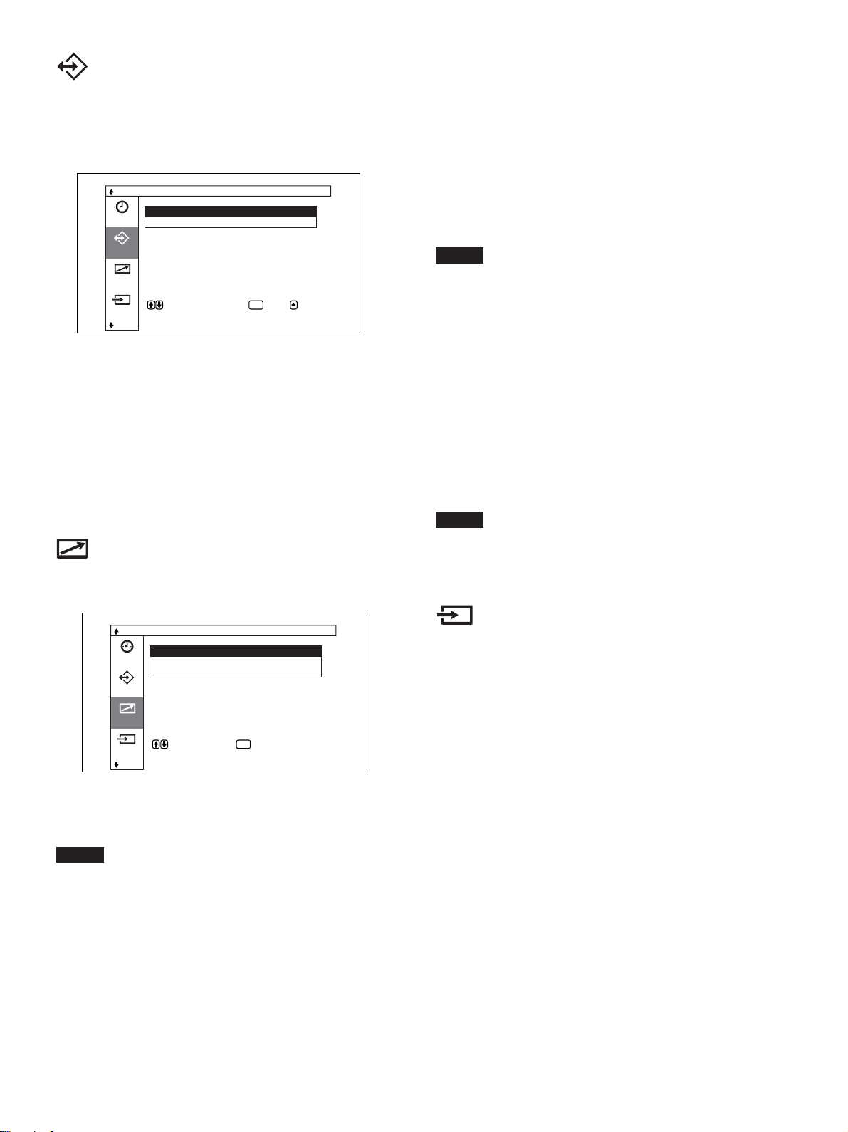
メモリーメニュー
画質/音質調整メニューと画面モード調整メニュ ーの調整値をナ
ンバー1〜20のメモリ ー に保存したり、呼び出したりするメニュー
です。
調整値の保存 / 呼出
呼出
保存
タイマー
メモリー
リモー ト
で項目を選択します 。 または を押す
と設定メニューに入り ます 。
入力切換
ENTER
◆メモリー機能について詳しくは、「メモリ ーを使 う」(42(JP)ページ)を
ご覧ください。
呼出
保存した調整値を呼び出します。
保存
調整値を保存します。
リモートコントロール設定メニュー
リモートモード
リモートコマンダーのモードを切り換えます。
TV:ディ スプレイ または TVに付属しているリモートコマンダーか
ら操作するとき。
PJ:業務用プロジェクターに付属しているリモー トコマンダーか
ら操作するとき。
切: リモートコマンダーから操作しないと き。(リモー トコマンダー
からは操作できなくなります。 )
ご注意
モードを切り換える場合は、ディ スプレイ 本体のボタン を使用してく
ださい。 リモー トコマンダーでは切り換えできません。
◆使用できるリモートコ マン ダー や 操 作につ い て 詳しくは、「他のリモート
コマンダーから操作する」(51(JP)ペ ージ) をご覧く ださい。
リモートオンリー
「リモー トオンリー」を入にすると、ディ スプレイ 本体のボタンが効か
なく なり、ディ スプレイ の操作はリ モートコマンダーでのみ行えるよ
うになります。
リモートオンリ ーモードを解除するには、リモー トコ マンダ ー で「リ
モートオンリー」 を切にして ください。
ご注意
電源コードを抜いたり、リモートコマンダーで電源を入/切して もリ
モートオンリーモー ドは解除できません。
リモー トコマンダーの操作に関する設定を行うメニュ ーです。
リモートコントロール設定
インデックス番号 : 1
リモートモード : TV
タイマー
リモートオンリー :
メモリー
リモー ト
で項目を選択し、 で決定します 。
入力切換
ENTER
インデックス番号
ディ スプレイ 本体のインデックス 番号を設定し ます。
ご注意
この項目を設定する 場合は、ディ スプレイ本体のボタ ンを使用して
ください。 リモートコマンダーでは設定できません。
◆インデッ ク ス番号について詳しくは、「特定のディスプレイ をリモー トコマ
ンダーで操作する」(49(JP)ページ)をご覧く ださい。
入力切換メニュー
入力信号の切り換えを設定するメニューです。
◆ 入力信号の切り換えについて詳しくは「入力信号を 切り換える」(29(JP)
ペー ジ)をご覧ください。
27
(JP)
Page 28
メニューで行う調整と設定
ステータスメニュー
ディ スプレイ 本体の内部状態を表示するメニューです。
ステータス
機種名: PFM—50C1
シリアル番号: 2000001
メモリー
累積通電時間: 00001H
ソフトウェアバ ージョン : 1 . 00
内部温度: OK
リモー ト
ファン: OK
入力切換
で項目を選択します 。
ステータス
機種名
機種名を表示します。
シリアル番号
シリアル番号を表示します。
累積通電時間
電源を入れていた累積通電時間を1時間単位で表示します。
ファン
本機には、冷却用ファンが内蔵されています。ファンが正常に動
いてい るかどうかを表示し ます。
OK:正常時
NG:異常時
このファンが 何らか の 異 常により停止したときは、 異常表示となり、
項目が赤色で点滅します。このと き 、1(スタンバイ)スイ ッチ/イ
ンジケーター部のSTANDBYインジケーターも点滅します。
ご注意
・「NG」という表示が赤色で点滅した場合は、お買い上げ店、ま
たはソニーのサー ビス窓口にご連絡ください。
◆ STANDBYインジケーターが点滅したり、異常表示になったりした とき
は、「自己診断機能」(49(JP)ページ) をご覧くださ い。
・冷却用ファンは本機の機内温度を検知して回転数を制御してい
ます。 そのために、周囲温度が上がるとファンの回転数が増え、
ファンの 回 転 音も大き くなります のでご注意ください。
ご注意
スタンバイ状態は累積通電時間に含まれません。
ソフトウェアバージョン
システム ソフトウェアのバージョ ンを表示します。
内部温度
ディ スプレイ の内部温度が正常かどうかを表示します。
OK:正常時
NG:異常時
異常時には異常表示となり、項目が赤色で点滅します。このと き 、
1(スタンバイ )スイッチ/イ ンジケーター部のSTANDBYインジ
ケー ターも点滅します。
ご注意
通風孔がふさがれたり、風通しの悪い状態で使用したりしている
と、「NG」とい う表 示が赤色で点滅することがあります。この場合
は、通風孔がふさがれていないか確認し、風通しをよくしてくださ
い。表示が正常になればそのままご使用いただけます。風通しを
よく して も 異常表示になる場合は、お買い上 げ店、またはソニーの
サー ビス窓口にご連絡ください。
◆ STANDBYインジケーターが点滅したり、異常表示になったりしたとき
は、「自己診断機能」(49(JP)ページ) をご覧くださ い。
28
(JP)
Page 29
画像を見る
準備
・ディ スプレイ の電源を入れてお きます。
・接続した機器の電源を入れ、映像ソースを再生します。
・電源投入時または入力切り換え 時に入力信号の種類と画質モー
ドを画面に表示させたいときは、各種切換メニューの「ステ ータ
ス表示」を入にしておきます。
・メニュー表示は日本語以外の言語にすることもできます。
◆詳しくは、「メニ ュ ー 表示の言語を選ぶ」(43(JP)ページ)をご覧く
ださい。
入力信号を切り換える
1 MENUボタンを押す。
メインメニューが表示されます。
画像を見る
ビデオ (コンポジット):ビデオ( VIDEO IN)端子の
COMPOSITEIN(COMPOSITE)端子に接続し
た機器の入力信号を選ぶ場合。
ビデオ (Y/C):ビデオ( VIDEOIN)端子のY/CIN(Y/
C)端子に接続した機器の入力信号を選ぶ場合。
オプションボード「BKM-B11」を装着している場合
ビデオ1(コンポジット):ビデオ1(VIDEO1IN)端子の
COMPOSITEIN(COMPOSITE)端子に接続し
た機器の入力信号を選ぶ場合。
ビデオ1(Y/C):ビデオ1(VIDEO1IN)端子のYCIN(Y/
C)端子に接続した機器の入力信号を選ぶ場合。
ビデオ2(D4):ビデオIN端子のD4端子に接続した機器
の入力信号を選ぶ場合。
選んだ入力信号がディスプレイ画面に表示されます。
カラー方式または水平/垂直周波数
入力系統
画質 / 音質調整
画質モード : スタン ダード
画質調整
画質/音質
音質調整
画面モード
各種切換
で項目を選択します 。 または を押す
と調整メニューに入ります 。
初期設定
ENTER
2 M/mボタンで「入力切換」を選び、ENTERボタンを押す。
入力切換メニューが表示されます。
入力切換
入力1(RGB)
入力1(コン ポ ーネ ント )
タイマ ー
入力2(RGB)
入力2(コン ポ ーネ ント )
ビデオ( コ ン ポ ジット)
メモリー
ビデオ( Y/C)
リモート
で選択します。 を押すと実行します 。
入力切換
ENTER
3 M/mボタ ンで表示したい入力信号を選び、ENTERボタンを
押す。
入力1(RGB):入力1端子に接続した機器の入力信号
(RGB信号)を選ぶ場合。
入力1(コンポーネント) :入力1端子に接続した機器の入
力信号(コンポーネント信号)を選ぶ場合。
入力2(RGB):入力2端子に接続した機器の入力信号
(RGB信号)を選ぶ場合。
入力2(コンポーネ ント):入力2端子に接続した機器の入力
信号(コン ポーネ ント信号)を選ぶ場合。
入力1(RGB)
1024× 768/ 60
スタンダード
画質モード
ディ スプレイに付属しているリモー トコマン ダーから入力を切り
換え る こ ともでき ます。
ご注意
・ディ スプレイ へのビデオ入力信号は、TBC(タイムベースコレク
ター)付きの入力ソ ース機器からの入力をおすすめします。TBC
のかかっていない信号を入力すると、同期の乱れにより映像が
消え る こ と があ ります。
・同じフォーマットの信 号を複 数の系統から入力している場合、画
質モードの設定は最新の設定値になります(同フォーマットの
み)。
29
(JP)
Page 30
画像を見る
入力信号と画質モードの情報とディス
プレイの設定状態の表示について
電源投入時ま たは入力切り換え時に、入力信号と画質モードの情
報が約5秒間画面に表示されます。
情報を画面に表示しないようにするときは、以下の手順に従って
設定してください。
1 各種切換メニューから、M/mボタンで「ス テ ータス表示」を選
び、ENTERボタンを押す。
以下の画面が表示されます。
各種切換
消費電力 : 標準
スピーカー出力 : 入
画質/音質
クローズドキャプション:
ステータス表示 :
スクリーンセーバー
画面モード
カラーマトリクス
HDモード :
RGBモード : PC
各種切換
で選択します 。 を押すと戻ります。
初期設定
ENTER
入
切
2 M/mボタンで 「ステー タス表示」を切にし、ENTERボタンを
押す。
ステータス表示させるには
手順2で「 ステータス表示」を入にします。
(工場出荷時は入に設定されています。)
ご注意
本機に付属しているリモー トコマンダーのDISPLAYボタンを押して、
いつでも 必要なとき に 入力信号の情報 および画質モードを表示する
こともでき ます。
30
(JP)
Page 31

画像を見る
入力プリセット信号
信号名称 カラー方式または水平/
垂直周波数表示
コンピューター信号
1 VGAa)-1(VGA350) 31.5kHz 70.1Hz
2640×350@85Hz(VESAb)STD) 37.9kHz 85.1Hz
3 640×400@85Hz(VESASTD) 37.9kHz 85.1Hz
4 640×480@60Hz(VESASTD) 31.5kHz 59.9Hz
5 Macc)13" 35.0kHz 66.7Hz
6 640×480@72Hz(VESASTD) 37.9kHz 72.8Hz
7 640×480@75Hz(VESASTD) 37.5kHz 75.0Hz
8 640×480@85Hz(VESASTD) 43.3kHz 85.0Hz
9 852×480@60Hz(I/ODATA)
10 VGA(VGATEXT) 31.5kHz 70.1Hz
11 720×400@85Hz(VESASTD) 37.9kHz 85.0Hz
12 800×600@56Hz(VESASTD) 35.2kHz 56.3Hz
13 800×600@60Hz(VESASTD) 37.9kHz 60.3Hz
14 800×600@72Hz(VESASTD) 48.1kHz 72.2Hz
15 800×600@75Hz(VESASTD) 46.9kHz 75.0Hz
16 800×600@85Hz(VESASTD) 53.7kHz 85.1Hz
17 Mac16" 49.7kHz 74.6Hz
18 1024×768@60Hz(VESASTD) 48.4kHz 60.0Hz
19 1024×768@70Hz(VESASTD) 56.5kHz 70.1Hz
20 1024×768@75Hz(VESASTD) 60.0kHz 75.0Hz
21 1024×768@85Hz(VESASTD) 68.7kHz 85.0Hz
22 1152×864@75Hz(VESASTD) 67.5kHz 75.0Hz
23 Mac21" 68.7kHz 75.1Hz
24 1280×960@60Hz(VESASTD) 60.0kHz 60.0Hz
25 1280×960@85Hz(VESASTD) 85.9kHz 85.0Hz
26 1280×1024@60Hz(VESASTD) 64.0kHz 60.0Hz
27 1280×1024@75Hz(VESASTD) 80.0kHz 75.0Hz
28 1280×1024@85Hz(VESASTD) 91.1kHz 85.0Hz
29 1600×1200@60Hz(VESASTD) 75.0kHz 60.0Hz
30 856×480@60Hz(Matrox)
31 856×480@59.6Hz(Matrox)
32 856×480@60.1Hz(Matrox)
SDTV/HDTV
1 PAL PAL
2 NTSC NTSC
3 SECAM SECAM
4 NTSC4.43 NTSC4.43
5 PAL60 PAL60
6 PAL-M PAL-M
7 PAL-N PAL-N
8 575/50i 575/50I
9 480/60i 480/60I
10 1080/24psf 1080/48I
11 1080/50i 1080/50I
12 576/50p 576/50P
13 480/60p 480/60P
14 1080/60i 1080/60I
15 720/60p 720/60P
d)
31.7kHz 60.0Hz
e)
30.2kHz 60.0Hz
e)
30.1kHz 59.6Hz
e)
30.1kHz 60.1Hz
a) VGAは米国InternationalBusinessMachinesCorporationの登録商
標です。
b) VESAはVideoElectronicsStandardsAssociationの登録商標です。
c) Mac(Macintosh)はAppleComputer,Incの登録商標です。
d) I-ODATA機器社製のグラフィックアクセラレータ ーボー ドを使用し
た場合。
e) MatroxGraphicsInc.製のグラフィックスカードを使用した場合。
ご注意
・HDTV信号を入 力する場合、同期信号は3値同期信号を
INPUT1またはINPUT2端子のRGB/YUV端子(D-sub15ピン
コネク ター)の 2 番ピンに入力して ください。
・No.29のコンピューター信号を入力する場合、画面モード調整メ
ニューの水平サイズ、水平位置、垂直サイズ、垂直位置をいず
れも標準位置(00)にし、ズームを標 準に設定 してください。 こ
れらを動かして使用すると、画像が乱れることがあります。
・PFM-50C1で DVD信号を入力した場合、画像の色を薄く感じ
たら、画質調整メニューの「色の濃さ」でお好みの色の濃さに調
整してく ださい。
・位相を再調整すると解像度が低下します。
入力信号/ディスプレイ設定情報の画面表示
画面表示 意味
640×480/60(例) コンピューター信号が入力されています。
525/60(例) コンポーネント信号が入力されています。
NTSC(例) NTSC信号が入力されています。
標準信号ではありま 受像できない信号が入力されています。
せん
信号が入力されていま 入力信号がありません。
せん
入力1(RGB) 入力1端子の入力モードはRGBです。
入力1(コンポーネント) 入力 1端子の入力モードはコ ンポーネント
ビデオです。
ビデオ(コンポジ ット) ビデオ(VIDEO1IN)端子の
COMPOSITEIN(VIDEO1IN
COMPOSITE)が選択されています。
ビデオ(Y/C) ビデオ(VIDEO1IN)端子のY/CIN
(VIDEO1INY/C)が選択されています。
(JP)
31
Page 32

画像を見る
画面表示を切り換える
字幕を表示させる
1 MENUボタンを押す。
メインメニューが表示されます。
画質 / 音質調整
画質モード : スタン ダード
画質調整
画質/音質
音質調整
画面モード
各種切換
で項目を選択します 。 または を押す
と調整メニューに入ります 。
初期設定
ENTER
2 M/mボタンで「各種切換」を選び、ENTERボタンを押す。
各種切換メニューが表示されます。
各種切換
消費電力 : 標準
スピーカー出力 : 入
画質/音質
クローズドキャプション:切
ステータス表示 : 入
スクリーンセーバー
画面モード
カラーマトリクス
HDモード :
RGBモード : PC
各種切換
で項目を選択し 、 または で決定しま
す 。
初期設定
ENTER
節電モード機能
節電しながら映像を見ることができます。
1 MENUボタンを押す。
メインメニューが表示されます。
画質 / 音質調整
画質モード : スタン ダード
画質調整
画質/音質
音質調整
画面モード
各種切換
で項目を選択します 。 または を押す
と調整メニューに入ります 。
初期設定
ENTER
2 M/mボタンで「各種切換」を選び、ENTERボタンを押す。
各種切換メニューが表示されます。
各種切換
消費電力 : 標準
スピーカー出力 : 入
画質/音質
クローズドキャプション:切
ステータス表示 : 入
スクリーンセーバー
画面モード
カラーマトリクス
HDモード :
RGBモード : PC
各種切換
で項目を選択し 、 または で決定しま
す 。
初期設定
ENTER
3 M/mボタ ンで「ク ロ ーズドキャ プション」を選び、ENTERボタ
ンを押す。
以下の画面が表示されます。
各種切換
消費電力 : 標準
スピーカー出力 : 入
画質/音質
クローズドキャプション:
ステータス表示 : 入
スクリーンセーバー
画面モード
カラーマトリクス
HDモード :
RGBモード : PC
各種切換
で選択します 。 を押すと戻ります。
初期設定
切
キャプチャー1
キャプチャー2
テキスト1
テキスト2
ENTER
4 M/mボタンで表示する字幕のタイプを選ぶ。
切:字幕を表示しない
キャプチャー1:画像に重ねて、言語1の字幕を表示する
キャプチャー2:画像に重ねて、言語2の字幕を表示する
テキスト1:字幕の背景を黒くして、言語1の字幕を表示する
テキスト2:字幕の背景を黒くして、言語2の字幕を表示する
5 MENUボタンを押す。
各種切換メニューに戻ります。
3 M/mボタンで「消費電力」を選び、ENTERボタンを押す。
以下の画面が表示されます。
各種切換
消費電力
スピーカー出力 :
画質/音質
クローズドキャプション:
ステータス表示 : 入
スクリーンセーバー
画面モード
カラーマトリクス
HDモード :
RGBモード : PC
各種切換
で選択します 。 を押すと戻ります。
初期設定
ENTER
標準
減
4 M/mボタンで消費電力のモードを選ぶ。
標準:節電しない
減:節電する
節電モードを減にすると、画面の明るさを下げて、節電しなが
ら見るこ とができます。
ご注意
・「消費電力:減」のときに電源を切ると、次に電源を入れたとき
も「消費電力:減」のままになります。
・画質モードで「ユーザー1〜3」を選んでいるとき は 、「消費電力:
減」でも 、画質を調整できます。ただし 、コン トラストや明るさを 上
げる と節電にならなくなる場合があり ます。
32
(JP)
Page 33

画質を選ぶ/画質を調整する
画質を選ぶ
映像の種類や周囲の明るさに合わせて画質を選ぶことができま
す。
1 MENUボタンを押す。
メインメニューが表示されます。
画質 / 音質調整
画質モード : スタン ダード
画質調整
画質/音質
音質調整
画面モード
各種切換
で項目を選択します 。 または を押す
と調整メニューに入ります 。
初期設定
2 M/mボタ ンで「画質/音質」を選び、ENTERボタンを押す。
画質/音質調整メニューが表示されます。
画質 / 音質調整
画質モード : スタン ダード
画質調整
画質/音質
音質調整
画面モード
各種切換
で項目を選択し、 または で決定しま
す 。
初期設定
ENTER
ENTER
画質を調整する
画像を見ながら、コン トラスト、明るさ、色 の濃さ、色あいなどを調
整することができます。また、入力信号ごとに調整を行い、調整値
をメモ リーすることが できます。
画質モードを「 ユーザー 1 〜 3 」のいずれかにしてください。
コントラスト、明るさ、
色の濃さ、色あいなどを調整する
MENUボタンを押してメインメニューを表示し、画質調整メニュー
から調整したい項目に応じて、「コントラスト」、「明るさ」、「色の濃
さ」、「色あい」、「シャ ー プネス」、「NR(ノイズリダクション)」「シネ
マドライ ブ」、「ダイナ ミックピクチャー」、「色温度」、「色補正」、「ガ
ンマ補正」を調整します。
コントラスト
M/mボタ ンで「コ ントラスト」を選び、ENTERボタンを押し、M/m/
</,ボタンでコントラストを調整しま す 。
最小(0)〜最大(255)の範囲で設定できます。
M/,:コン トラストが 強くなる
m/<:コン トラストが 弱くなる
3 M/mボタンで 「画質モード」を選び、ENTERボタンを押す。
以下の画面が表示されます。
画質 / 音質調整
画質モード : ダイナミック
画質調整
画質/音質
音質調整
画面モード
各種切換
で選択します 。 を押すと戻ります。
初期設定
ENTER
スタンダード
ダイナミック
ユーザー1
ユーザー2
ユーザー3
4 M/mボタンで画質を選び、ENTERボタンを押す。
スタンダ ード:適度なコントラス トと輪郭強調によりきめ細かい
質感のあるリア ルな画 質になります 。
ダイナミ ック:映像の輪郭とコントラストを最大限に上げた、メ
リハリの強い 画質になります。
ユーザー1〜3:画質調整メニューからお好みの画質を自由
に設定できます。
明るさ
M/mボタ ンで「明るさ」を選び、ENTERボタンを押し、M/m/</
,ボタンで画像の明るさを調整します。
最小(−128)〜最大(+127)の範囲で設定できます。
M/,:画像が明るくなる
m/<:画像が暗くなる
色の濃さ
M/mボタンで 「色の濃さ」を選び、ENTERボタンを押し、M/m/
</,ボタンでクロマを調整します。
最小(−128)〜最大(+127)の範囲で設定できます。
M/,:色が濃くなる
m/<:色が薄くなる
33
(JP)
Page 34

画質を調整する
色あい
M/mボタ ンで「色あい」を選び、ENTERボタンを押し、M/m/</
,ボタンで色あいを調整します。
赤(− 128)〜緑(+127)の範囲で設定できます。
M/,:画像が緑がかる
m/<:画像が赤みがかる
シャープネス
M/mボタンで 「シャ ープネス」を選び、ENTERボタンを押し、M/
m/</,ボタ ンで画像のシャープネスを調整します。
最小(−5)〜最大(+5)の範囲で設定できます。
M/,:画像をくっき りと表示する
m/<:画像をやわらかく表示する
NR(ノイズリダクション)
映像のざらつきや色ノイズを軽減することができます。
1 M/mボタンで 「NR」を選び、ENTERボタンを押す。
以下の画面が表示されます。
画質 / 音質調整
画質調整( ユーザー1 )
コントラスト
明るさ
画質/音質
色の濃さ
色あい
シャープネス
画面モード
NR :
シネマドライブ :
ダイナミックピクチャー:
各種切換
で選択します 。 を押すと戻ります。
初期設定
ENTER
切
弱
中
強
2 M/mボタンで NR のモードを選び、 ENTERボタンを押す。
切:映像信号をそのまま表示する
弱:NR処理を弱く設定するとき
中:NR処理を中程度に設定するとき
強:NR処理を強く設定するとき
シネマドライブ
フィルム(24コマ)で撮影された映像を自動検出し、フィルム映像
特有の滑らかな動きのある映像を再現するこ と ができます。
1 M/mボタンで 「シネマ ドライ ブ 」 を選び、ENTERボタンを押
す。
以下の画面が表示されます。
画質 / 音質調整
画質調整( ユーザー1 )
コントラスト
明るさ
画質/音質
色の濃さ
色あい
シャープネス
画面モード
NR : 切
シネマドライブ :
ダイナミックピクチャー:
各種切換
で選択します 。 を押すと戻ります。
初期設定
ENTER
自動
切
2 M/mボタンでシネマ ドライ ブのモードを選び、 ENTERボタン
を押す。
自動:フィルム映像に最適な信号処理を行う
切:映像信号をそのまま表示する
ダイナミックピクチャー
白をよ り 白 く、黒をより黒く してコントラストを強めます。
1 M/mボタ ンで「ダイナ ミックピクチャー」 を選び、ENTERボタ
ンを押す。
以下の画面が表示されます。
画質 / 音質調整
画質調整( ユーザー1 )
コントラスト
明るさ
画質/音質
色の濃さ
色あい
シャープネス
画面モード
NR : 切
シネマドライブ :
ダイナミックピクチャー:
各種切換
で選択します 。 を押すと戻ります。
初期設定
ENTER
入
切
34
2 M/mボタ ンでダイ ナミックピクチャーのモー ドを選び、 ENTER
ボタ ンを押す。
入:ダイナミックピクチャー機 能を 使う
切:ダイナミックピクチャー機 能を 使わない
(JP)
Page 35

画質を調整する
初期設定
色温度
色温度を設定します。「高」「中」「低」のほか、各ゲインを好みに
合わせて細かく調整することもできます。 調整した色温度は、3つ
まで登録できます。登録した色温度の名前を変更することもでき
ます (6 文字まで)。
1 M/mボタンで「色温度」を選び、ENTERボタンを押す。
2 M/mボタンで色温度を選び、ENTERボタンを押す。
高:色温度を高く設定するとき
中:色温度を中程度に設定するとき
低:色温度を低く設定するとき
User1〜3:各ゲ インを細かく設定するとき
「高」「中」「低」を選んだ場合には、画質調整メニューに戻り
ます。
「User1〜3」を選んだ場合
「User1〜3」を選んだ場合には、以下の画面が表示されま
す。
画質 / 音質調整
画質調整( ユーザー1 )
色温度 : User1
赤ゲイン
画質/音質
緑ゲイン
青ゲイン
名称登録
画面モード
各種切換
で項目を選択し、 または で決定しま
初期設定
す 。
ENTER
(2) M/m/</,ボタ ンでゲインを調整し (0〜255)、ENTER
ボタ ンを押す。
色温度メニュー画面に戻ります。
調整した色温度の名前の変更は、以下の手順で行います。
(3) M/m ボタンで「名称登録」を選び、ENTERボタンを押
す。
以下の画面が表示されます。
画質 / 音質調整
画質調整( ユーザー1 )
色温度 : User1
名称登録
画質/音質
0123456789ABCDEFGH
IJKLMNOPQRSTUVWXYZ
abcde fgh i j k lmnopq r
画面モード
s t uvwxyz( )[]〈〉+−×/
=%℃& ; : . ',←→ 終了
各種切換
で選択します 。 を押すと決定しま
す 。
初期設定
ENTER
キャラクター一覧
(4) M/m/</, ボタンでキャラ ク タ ー一覧から文字や記号
を選び、ENTERボタンを押す。
選んだ文字が入力されます。間違えたときは画面上の
「<」を選ぶ と1文字戻りますので、選び直してください。
◆初期設定メニューの「メ ニ ュ ー キ ー動作」(26(JP)ページ)が「戻
る」に設定されている ときは、リモコンの M/mボタ ンはカーソルを
左右に移動さ せます。M/mボタンでカーソルを上下に移動さ せた
い場合は、メニューキー動作 の設定を 「入/切」にしてください。
(1) M/m ボタンで設定したいゲインを選び、ENTERボタンを
押す。
以下の画面が表示されます。
赤ゲイン 00
初期設定
(5) 手順(4)を繰り返し、名前の変更が終わったら「終了」を
選び、ENTERボタンを押す。
色温度メニュー画面に戻ります。
35
(JP)
Page 36

画質を調整する
色補正
美しく 健康的な色を再現することができます。
1 M/mボタンで「色補正」を選び、ENTERボタンを押す。
以下の画面が表示されます。
画質 / 音質調整
画質調整( ユーザー1 )
シャープネス
NR : 切
画質/音質
シネマドライブ :
ダイナミックピクチャー:
色温度 : 高
画面モード
色補正 :
ガンマ補正 :
標準
各種切換
で選択します 。 を押すと戻ります。
初期設定
ENTER
入
切
2 M/mボタンで色補正のモードを選び、ENTERボタンを押す。
入:色補正をかける
切:色補正をかけない
ガンマ補正
映像の明暗部分のバランスを自動的に調整することができます。
1 M/mボタ ンで 「ガ ンマ補正」を選び、ENTERボタンを押す。
以下の画面が表示されます。
画質 / 音質調整
画質調整( ユーザー1 )
シャープネス
NR : 切
画質/音質
シネマドライブ :
ダイナミックピクチャー:
色温度 : 高
画面モード
色補正 :
ガンマ補正
標準
各種切換
で選択します 。 を押すと戻ります。
初期設定
ENTER
高
中
低
ご注意
・RGB信号を入力している場合、色あいと色の濃さは調整できま
せん。
・コンポーネント信 号を入 力して いる場合、色あいは調整できませ
ん。
・PAL、PAL-M、PAL-N、PAL60およびSECAM方式の入力信号
の場合、色あいは調整できません。
・白黒信号を入力しているときは、色の濃 さと色あいは調整できま
せん。
調整した画質を出荷時の設定値に戻す
1 画質調整メニューから、M/mボタンで「標準」を選び、
ENTERボタンを押す。
以下の画面が表示されます。
画質 / 音質調整
画質調整( ユーザー1 )
シャープネス
NR : 切
画質/音質
シネマドライブ :
ダイナミックピクチャー:
色温度 : 高
画面モード
色補正 :
ガンマ補正 :
標準
各種切換
で選択します 。 を押すと戻ります。
初期設定
ENTER
取消
実行
2 M/mボタンで「実行」を選び、ENTERボタンを押す。
画質調整メニューの項目が工場出荷時の 設定値に戻ります。
リセットを中止するには
ENTERボタンを押す前にMENUボタンを押してください。また
は、M/mボタ ンで「取消」を選びENTERボタンを押してください。
2 M/mボタ ンでガンマ補正のモー ドを選び、ENTERボタンを押
す。
高:ガンマ補正を強く かけると き
中:ガンマ補正を中程度にかけると き
低:ガンマ補正を弱く かけると き
(JP)
36
Page 37

映像を拡大する
通常のテレビ放送やワイドク リアビ ジョンなど、映像の種類に合わ
せて画面いっぱいに拡大表示することが できます。
ワイドモードには以下の種類があります。
オリジナルの映像 拡大した映像
(映像の種類)
・通常の4:3映像をワイド
ズームに設定し た とき(画
面横縦比4:3)
違和感少なく画面いっぱい
に拡大します。
映像を拡大する
オートワイドを設定する
一部の通常のテレビ放送やワイドクリアビ ジョン放送などでは、映
像を判別するための識別制御信号が映像信号と重ねて送られて
います。オートワイド機能は、 識別制御信号に基づいて映像を忠
実に再現したり、識別制御信号に関係なくあらゆる映 像を 最適な
サイ ズで拡大表示することができます。
また、横縦比が4:3の通常のテレビ放送やBS放送を、横縦比16:
9に拡大して表示することもできます。
識別制御信号とは
オリジナル映像の横縦比をテレビで忠実に再現するためのコント
ロール信号です。この信号を含む映像には以下のも のがあります。
・ワイドクリアビジョン放送
・横縦比情報の入ったビデオカメラなどの記録映像(ID-1方式)
・横縦比を4:3にする信号の入ったテレビ放送
・D4入力端子から受ける横縦比情報の入った映像
・ワイドクリ アビジョン放送
(横縦比16:9)
・ビスタビジョンなど映像中
に字幕が入った横長の映
画( 横縦比1.85:1)
・横縦比情報の入ったビデ
オカメラや DVDソフトなど
の映像( ID-1方式)
・横縦比情報の入ったビデ
オカメラや DVDソフトなど
の映像( ID-1方式)
・シネマビジ ョンなど映像の
外に字幕のある横長の映
画( 横縦比2.35:1)
画面の左右に合わせていっ
ぱいに拡大します。(映像の
種類によって、上下に黒い
帯が残ることが あります。)
天地はそのままで、左右を
画面いっぱいに引き伸ばし
ます。
画面の左右に合わせていっ
ぱいに拡大しながら、字幕
部分だけを圧縮して画面に
入れます。
1 MENUボタンを押す。
メインメニューが表示されます。
画質 / 音質調整
画質モード : スタン ダード
画質調整
画質/音質
音質調整
画面モード
各種切換
で項目を選択します 。 または を押す
と調整メニューに入ります 。
初期設定
ENTER
2 M/mボタンで 「画面モード」を選び、ENTERボタンを押す。
画面モード調整メ ニュー が表示されます。
画面モード調整
オートワイド設定
ワイド切換 : ノーマル
画質/音質
ズームサイズ :
画像サイズ
画像位置
画面モード
ドット調整
標準
各種切換
で項目を選択します 。 または を押す
と設定メニューに入ります 。
初期設定
ENTER
・オートワイド「入」で、4:3映像
を「ノー マ ル」(出荷時は
「ノ ーマル」)に設定し たとき
拡大せずに、横縦比4:3のま
まの映像になり ます。
37
(JP)
Page 38

映像を拡大する
3 M/mボタ ンで「オートワイド設定」を選び、ENTERボタンを押
す。
以下の画面が表示されます。
画面モード調整
オート ワイド設定
オートワイド :切
4:3映像 :
画質/音質
画面モード
各種切換
で項目を選択し、 または で決定しま
す 。
初期設定
ENTER
4 M/mボタンで 「オートワイド」を選び、ENTERボタンを押す。
以下の画面が表示されます。
整調ドーモ面画
画質/音質
画面モード
各種切換
で選択します 。 を押すと戻ります。
初期設定
定設ドイワトーオ
ドイワトーオ
像映3:4
ENTER
切
入
5 M/mボタンでオートワイドの設定を選ぶ。
切:映像をそのまま表示する
入:最適な横縦比に拡大して映像を表示する
6 ENTERボタンを押す。
3の画面に戻ります。
7 M/mボタンで「4:3映像」を選び、ENTERボタンを押す。
以下の画面が表示されます。
整調ドーモ面画
オートワイド :入
画質/音質
画面モード
各種切換
で選択します 。 を押すと戻ります。
初期設定
定設ドイワトーオ
像映3:4
ENTER
ノーマル
ワイド ズーム
8 M/mボタンで 4:3映像のモードを選ぶ。
ノーマ ル:4:3の映像をそのまま表示する
ワイドズーム :4:3の映像を16:9に拡大して表示する(識別制
御信号のない場合)
ワイド切換を設定する
映像の種類に 関係なく、お好きな ワイドモー ドで画面を拡大表示す
ることが できます。
1 画面モード調整メニューか ら 、M/mボタンで 「ワ イド切換」を
選び、ENTERボタンを押す。
以下の画面が表示されます。
画面モード調整
オートワイド設定
ワイド切換 :
画質/音質
ズームサイズ :
画像サイズ
画像位置
画面モード
ドット調整
標準
標準
各種切換
で選択します。 を押すと戻ります。
初期設定
ENTER
ワイドズーム
ズーム
フル
字幕入
ノーマル
2 M/mボタンでワイドモードを選ぶ。
ワイドズーム : 4:3の画像を 16:9 に画面いっぱいに拡 大しま
す。
ズーム:画面の左右に合わせていっぱいに拡大す る(映像
の種類に よっ ては上下に黒い帯が残ることがあります。)
フル : 天地をそのままにして、映像の左右を画面いっぱいに
引き伸ばす
字幕入:画面の左右に合わせていっぱいに拡大し、字幕部
分のみを圧縮して表示する
ノーマ ル:拡大せずにそのまま表示する
3 ENTERボタンを押す。
画面モードメニューに戻ります。
ご注意
・ワイド切換を設定すると、オートワイド機能が働き ません。オートワ
イド機能を使いたい場合は、「入」に再設定してください。
・映像の種類やサイズによっては、画面の上下が欠けたり、字幕
が入りきらな い 場 合 が あります。そのような場合は、画像のサイ
ズや位置を調整してください。
・本機を営利目的、または公衆に視聴させることを目的として喫茶
店、ホテルな どに置き、ワイド切換機能等を利用して画面の圧縮
や引き伸ばし等を行いますと、著作権法上で保護されている著
作者の権利を侵害する恐れがありますので、ご注意願います。
・本機は、各種のワイド切換機能を備えています。テレビ番組など
ソフ トの映 像比率と異なるモードを選 択されますと、 オリ ジナルの
映像とは見え方に差が出 ます。この点にご留意の上、ワイド切換
をお選びください。
9 ENTERボタンを押す。
オートワイド設定に戻ります。
(JP)
38
Page 39

画像のサイズや位置を調
初期設定
初期設定
整する
画像の大きさや位置がディ スプレイ画面に合っていないときは、位
置を調整した り 、縦・横方向に画像のサイズを変えたりすることが
でき ます。
◆この取扱説明書では、メニューキー動 作が 「入/切」に設定されてい
る状態での操作を説明していま す 。画面モード調整メニュ ーについて
詳しく は、「画面モード調整メニュー」(23(JP)ページ)をご覧く ださい。
画像のサイズを変える
画像のサイズや位置を調整する
画像の位置を調整する
1 画面モード調整メ ニュー か ら 、M/mボタ ンで「画像位置」を
選び、ENTERボタンを押す。
以下の画面が表示されます。
水平位置 00
垂直位置 00
初期設定
1 画面モードメニューからM/mボタ ンで「画像サイズ」を選び、
ENTERボタンを押す。
以下の画面が表示されます。
水平サイズ 00
垂直サイズ 00
初期設定
2 M/m/</,ボタンで水平方向/垂直方向のサイズを調整
する。
</,:水平方向のサイズを調整する
M/m:垂直方向のサイズを調整する
画像の水平方向のサイズは、画面上に最小(−128)〜最大
(+127)の調整値で表示されます。垂直方向のサイズは、画
面上に最小(−128)〜最大(+127)の調整値で表示され
ます。工場出荷時は00(標準位置)に設定されています。
2 M/m/</,ボタンで水平方向/垂直方向に動かす。
</,:画像が左/右に動く
M/m:画像が上/下に動く
画像の水平位置は、画面上に左(128)〜右(127)の調整
値で表示されます。画像の垂直位置は、画面上に下
(128)〜上(127)の調整値で表示されます。工場出荷時は
00(標準位置)に設定 されていま す。
3 ENTERボタンを押す。
画面モード調整メ ニュー に戻ります。
3 ENTERボタンを押す。
画面モード調整メ ニュー に戻ります。
39
(JP)
Page 40

画像のサイズや位置を調整する
初期設定
ドット位相を調整する
文字や縦線のエッジにチリチリとし たノイズ が 多 いときに、ドッ ト位
相と水平総ドット数を調整します 。
ご注意
コンピューター信号に対して有効です。
1 画面モード調整メニューか らM/mボタ ンで 「ドッ ト調整」を選
び、ENTERボタンを押す。
以下の画面が表示されます。
画面モード調整
ドット調整
自動調整
ドット位相
画質/音質
水平総ドット数 : 1344
標準
画面モード
各種切換
で項目を選択し、 または で決定しま
す 。
初期設定
ENTER
2 ドッ ト位 相と水平総ドッ ト数 の調 整には、自動調整と手動調整
の2通りがあります。
自動調整する場合
(1) M/m ボタンで「自動調整」を選び、ENTERボタンを押
す。
以下の画面が表示されます。
画面モード調整
ドット調整
自動調整
ドット位相
画質/音質
水平総ドット数 : 1344
標準
画面モード
標準
各種切換
で選択します 。 を押すと戻ります。
初期設定
(2) M/m ボタンで「実行」を選び、ENTERボタンを押す。
自動的にドッ ト位相と水平総ドット数が調整されます。
ENTER
取消
実行
手動調整する場合
(1) M/mボタ ンで 「 ドッ ト位相」または 「水平総ドッ ト数」 を選
び、ENTERボタンを押す。
以下の画面が表示されます。(下図は「ドッ ト位相」を選ん
だ場合)
ドット位相 31
初期設定
(2) M/mボタ ンで文字や縦線が最もきれいに見える状態に調
整し、 ENTERボタンを押す。
ご注意
絵柄によっては自動調整でもノイズが消えないときがあります。こ
の場合は手動調整をしてください。
ドット調整項目を出荷時の設定に戻すには
ドッ ト調 整メニューから、 M/mボタンで「標準」を選び、ENTERボ
タンを 押した 後で、M/mボタ ンで「実行」を選び、ENTERボタン
を押 してください。
設定した画面モードメニューの調整値
を出荷時の設定値に戻す
1 画面モード調整メニューか ら 、M/mボタ ンで「標準」を選び、
ENTERボタンを押す。
以下の画面が表示されます。
画面モード調整
オートワイド設定
ワイド切換 : ノーマル
画質/音質
ズームサイズ :
画像サイズ
画像位置
画面モード
ドット調整
標準
各種切換
で選択します 。 を押すと戻ります。
初期設定
ENTER
取消
実行
40
2 M/mボタンで「実行」を選び、ENTERボタンを押す。
画面モード調整メニューの項目が工場出荷時の設定値に戻
ります 。
リセットを中止するには
ENTERボタンを押す前にMENUボタンを押してください。また
は、M/mボタ ンで「取消」を選びENTERボタンを押してください。
(JP)
Page 41

音質を調整する
音質を調整する
音の高音、低音、バランスを調整することができます。また、 サラ
ウン ドモードを設定することができます。
高音、低音、バランスなどを調整する
MENUボタンを押してメインメニューを表示し、音質調整メニュー
から調整したい項目に応じて、「高音」、「低音」、「バランス」、「サ
ラウン ド」を調整 します。
高音
M/mボタ ンで 「高音」を選び、ENTERボタンを押し、M/m/</
,ボタ ンで高音を調整します。
最小(−50)〜最大(+50)の範囲で設定できます。
M/,:高音が強くなる
m/<:高音が弱くなる
低音
M/mボタ ンで 「低音」を選び、ENTERボタンを押し、M/m/</
,ボタ ンで低音を調整します。
最小(−50)〜最大(+50)の範囲で設定できます。
M/,:低音が強くなる
m/<:低音が弱くなる
サラウンド
映像の種類に合わせて、サラウ ン ドモードを選ぶことができます。
1 M/mボタンで 「サラウ ンド」を選び、ENTERボタンを押す。
2 M/mボタンでモードを選 び、 ENTERボタンを押す。
切:サラウ ンド出力は しない
ホール:映画や音楽などのステレオ音声をより臨場感のある
音にする場合
シミュレー ト:通常の放送やニュース番組のモノラル音声を擬
似的にステレオ音声にして臨場感を高める場合
調整した音質を出荷時の設定に戻す
1 音質調整メニューから、M/mボタンで「標準」を選び、
ENTERボタンを押す。
以下の画面が表示されます。
画質 / 音質調整
音質調整( ユーザー1 )
高音
低音
画質/音質
バランス
サラウンド : 切
標準
画面モード
各種切換
で選択します 。 を押すと戻ります。
初期設定
ENTER
取消
実行
2 M/mボタンで「実行」を選び、ENTERボタンを押す。
音質調整メニューの項目が工場出荷時の 設定値に戻ります。
バランス
M/mボタ ンで 「バラ ンス」を選び、ENTERボタンを押し、M/m/
</,ボタ ンでバラ ンス を調整します。
左(50)〜右(50)の範囲で設定できます。
M/,:右側の音が強くなる
m/<:左側の音が強くなる
リセットを中止するには
ENTERボタンを押す前にMENUボタンを押してください。また
は、M/mボタ ンで「取消」を選びENTERボタンを押してください。
(JP)
41
Page 42

メモリーを使う
メモリーを使う
ある入力ソースからの映像がう まく表 示されるように調整したら、そ
の調整値をメモリーに保存しておくことが できます。 画質/音質調
整メ ニュ ーと画面モード調整メニュ ーの調整値をナ ンバー1 〜20
のメ モ リーに保存できます。保存する設定に名前をつけることもで
きます(6 文 字まで )。
複数の調整状態をすばやく切り換えられるので便利です。
現在の調整状態をメモリーする
4 M/mボタンで設定を保存したいメモリーナンバー(01〜20)
を選び、ENTERボタンを押す。
以下の画面が表示されます。
調整値の保存 / 呼出
保存
MEM 01
保存
タイマー
名称登録
メモリー
リモー ト
で項目を選択し、 または で決定しま
す 。
入力切換
ENTER
1 MENUボタンを押す。
メインメニューが表示されます。
画質 / 音質調整
画質モード : スタン ダード
画質調整
画質/音質
音質調整
画面モード
各種切換
で項目を選択します 。 または を押す
と調整メニューに入ります 。
初期設定
ENTER
2 M/mボタンで 「メモリー」 を選び、ENTERボタンを押す。
調整値の保存/呼出メニューが表示されます。
調整値の保存 / 呼出
呼出
保存
タイマー
メモリー
リモー ト
で項目を選択します 。 または を押す
と設定メニューに入り ます 。
入力切換
ENTER
3 M/mボタンで「保存」を選び、ENTERボタンを押す。
以下の画面が表示されます。
調整値の保存 / 呼出
保存
MEM 01
MEM 02
タイマー
MEM 03
MEM 04
MEM 05
メモリー
MEM 06
MEM 07
MEM 08
リモー ト
で項目を選択します 。
入力切換
5 M/mボタンで「保存」を選び、ENTERボタンを押す。
以下の画面が表示されます。
調整値の保存 / 呼出
保存
MEM 01
保存
タイマー
名称登録
メモリー
リモー ト
で選択します 。 を押すと戻ります。
入力切換
ENTER
取消
実行
6 M/mボタンで「実行」を選びENTERボタンを押す。
選んだメモリーナンバーに現在の調整値が保存されます。
設定に名前を付ける場合は、以下の手順で行います。
7 M/mボタンで「名称登録」を選び、ENTERボタンを押す。
以下の画面が表示されます。
調整値の保存 / 呼出
保存
名称登録 :MEM 01
タイマー
0123456789ABCDEFGH
IJKLMNOPQRSTUVWXYZ
abcde fgh i j k lmnopq r
メモリー
s t uvwxyz( )[]〈〉+−×/
=%℃& ; : . ' , ←→ 終了
リモー ト
で選択します 。 を押すと決定しま
す 。
入力切換
キャラクター一覧
ENTER
8 M/m/</,ボタンでキャ ラクター一覧から文字や記号を選
び、ENTERボタンを押す。
選んだ文字が入力されます。 間違えたときは画面上の「<」
を選ぶと1文字戻りますので、選び直してください。
◆初期設定メニューの「メ ニューキー動作」(26(JP)ページ)が「戻
る」に設定されていると きは、リモコンの M/mボタン はカーソルを
左右に移動させます。M/mボタ ンでカーソル を上下に移動さ せた
い場合は、メニューキー動作の設 定を 「入/切」にしてく ださい。
42
(JP)
Page 43

メモリーを使う/メニュー表示の言語を選ぶ
9 手順8を繰 り返し 、名前の入力が終わったら「終了」を選び、
ENTERボタンを押す。
4の画面に戻ります。
メモリーした設定値を呼び出す
1 調整値の保存/呼出メニューから、M/mボタ ンで 「呼出」を
選び、ENTERボタンを押す。
以下の画面が表示されます。
調整値の保存 / 呼出
呼出
元に戻す
MEM 01
タイマー
MEM 02
MEM 03
MEM 04
メモリー
MEM 05
MEM 06
MEM 07
リモー ト
で項目を選択します 。
入力切換
2 M/mボタンで設定を呼び出したいメモリーナンバー(01〜
20)にカーソルを移動する。
保存された調整値が呼び出されます。
呼び出す前の調整値に戻すには
「元に戻す」にカーソルを移動してください。
3 ENTERボタンを押す。
調整値の保存/呼出メニュー画面に戻ります。
メニュー表示の言語を選ぶ
メニュー表 示に使う言語を、 日本語、英語、ドイ ツ語、フランス語、
スペイン語、イタリア 語 の 6つの言語の中から選ぶことができます。
1 MENUボタンを押す。
メインメニューが表示されます。
画質 / 音質調整
画質モード : スタン ダード
画質調整
画質/音質
音質調整
画面モード
各種切換
で項目を選択します 。 または を押す
と調整メニューに入ります 。
初期設定
2 M/mボタンで「初期設定」を選び、ENTERボタンを押す。
初期設定メニューが表示されます。
初期設定
言語 : 日本語
カラー方式 :
画質/音質
MENU
キー動作 : 入 /切
画面モード
各種切換
で項目を選択し、 または で決定しま
す 。
初期設定
3 M/mボタンで「言語」を選び、ENTERボタンを押す。
以下の画面が表示されます。
ENTER
ENTER
初期設定
言語
カラー方式
画質/音質
画面モード
各種切換
初期設定
MENU
キー動作
標準
で選択します 。 を押すと戻ります。
日本語
ENGLI SH
DEUTSCH
FRANCAIS
ESPANOL
I TAL IANO
ENTER
4 M/mボタ ンで表示したい言語を選び、ENTERボタンを押す。
メニュー画面の言語が切り換わります。
日本語:日本語
ENGLISH:英語
DEUTSCH:ドイ ツ語
FRANÇAIS:フランス語
ESPAÑOL:スペイン語
ITALIANO:イタリア 語
(JP)
43
Page 44

スクリーンセーバー機能
スクリーンセーバー機能
4 M/mボタンで「画像反転」を選び、ENTERボタンを押す。
以下の画面が表示されます。
コンピューターの画像のように、 輝度の変化しない画像や静止画
の映像を長時間表示すると、画面に焼きつきや残像が生じること
があ ります。
これを補正 したり 、軽減させるた め、本機にはスクリーンセーバー
機能が搭載されています。スクリーンセーバ ー 機 能には、 画像の
色あいを反転させる(画像反転)、一定の時間がたつと画像の表
示位置を自動的に変える(自動表示位置移動)、の 2 種 類があり
ます。
画像の色あいを反転させる
1 MENUボタンを押す。
メインメニューが表示されます。
画質 / 音質調整
画質モード : スタン ダード
画質調整
画質/音質
音質調整
画面モード
各種切換
で項目を選択します 。 または を押す
と調整メニューに入ります 。
初期設定
ENTER
2 M/mボタンで「各種切換」を選び、ENTERボタンを押す。
各種切換メニューが表示されます。
各種切換
消費電力 : 標準
スピーカー出力 : 入
画質/音質
クローズドキャプション:切
ステータス表示 : 入
スクリーンセーバー
画面モード
カラーマトリクス
HDモード :
RGBモード : PC
各種切換
で項目を選択し 、 または で決定しま
す 。
初期設定
ENTER
3 M/mボタ ンで「スクリーンセーバー」を選び、ENTERボタンを
押す。
以下の画面が表示されます。
各種切換
スクリーンセーバー
画像反転 : 切
自動表示位置移動
画質/音質
画面モード
各種切換
で選択します 。 を押すと戻ります。
初期設定
ENTER
切
自動
入
5 M/mボタンで画像反転のモードを選ぶ。
切:画像を反転しない
自動:1日1回、設定した時 刻に画像の色あいを反転する
入:画像の色あいを反転する
「自動」を選びENTERボタンを押すと、以下の画面が表示さ
れます。
各種切換
スクリーンセーバー
画像反転 : 自動
反転開始時間 : 00 : 00
画質/音質
反転終了時間 : 00 : 00
画面モード
各種切換
で項目を選択し 、 または で決定しま
初期設定
す 。
(1) M/m ボタンで「反転開始時間」を選び、ENTERボタンを
押す。
以下の画面が表示さ れ、時間の背景が凸状に表示されま
す。
各種切換
スクリーンセーバー
画像反転 : 自動
反転開始時間 : 00:00
画質/音質
反転終了時間 : 00: 00
画面モード
各種切換
初期設定
ENTER
44
(JP)
各種切換
スクリーンセーバー
画像反転 : 切
自動表示位置移動
画質/音質
画面モード
各種切換
で項目を選択し、 または で決定しま
す 。
初期設定
ENTER
(2) M/m ボタンで時間を設定し、ENTERボタンを押す。
時間が確定し、分の背景が凸状に変わります。
(3) M/m ボタンで分を設定し、ENTERボタンを押す。
分が確定します。<ボタ ン を押すと5の画面に戻りま す。
◆本体のボタンで操作する場合はMENUボタンを押してメニュー
を閉 じ 、初期設定メニューで「メ ニューキー動作」(26(JP)ページ)
を「 戻る 」に設定します。本体のMENUボタンが<ボタ ンと同
じ動作をします。
Page 45

スクリーンセーバー機能/カラーマトリクスを調整する
(4) 反転開始時間と同様に、反転終了時間を設定する。
1日1回、反転開始時間に反転が始まり、反転終了時間
に反転表示が終了する設定になります。
ご注意
反転開始時間と反転終了時間に同じ時刻を設定すると、反転開
始時間の設定が優先され、反転終了時間になっても反転表示は
終了しません。
画像の表示位置を自動的に変える
1 スクリーンセーバーメニューから、M/mボタンで「自動表示位
置移動」を選び、ENTERボタンを押す。
以下の画面が表示されます。
各種切換
スクリーンセーバー
自動表示位置移動
表示位置移動 : 切
画質/音質
移動量 : 小
移動周期 : 5分
画面モード
各種切換
で項目を選択し 、 または で決定しま
す 。
初期設定
ENTER
5 M/mボタ ンで 「移動量」(移動の大きさ)または 「移動周期」
(移動の時間)を選び、ENTERボタンを押す。
選択できる移動量、移動周期は以下のとおりです。
移動量:小、中、 大
移動周期:10秒、30秒、1分、5分
以下の画面が表示されます。(下図は「移動量」を選んだ場
合)
各種切換
スクリーンセーバー
自動表示位置移動
表示位置移動 : 切
画質/音質
移動量 :
移動周期 :
画面モード
各種切換
で選択します 。 を押すと戻ります。
初期設定
ENTER
小
中
大
6 M/mボタ ンで移動量または移動周期を設定し、ENTERボタ
ンを押す。
画像反転と自動表示位置移動の両方を入にすると
画像が反転中に一定時間がたつと、反転した画像が表示位置を
変えて表示されます。
2 M/mボタンで「表示位置移動」を選び、ENTERボタンを押
す。
以下の画面が表示されます。
各種切換
スクリーンセーバー
自動表示位置移動
表示位置移動 :
画質/音質
移動量 : 小
移動周期 : 5分
画面モード
各種切換
で選択します 。 を押すと戻ります。
初期設定
ENTER
切
入
3 M/mボタンで表示位置移動のモードを選ぶ。
切:表示位置を移動しない
入:表示位置を移動する
4 ENTERボタンを押す。
1の画面に戻ります。
カラーマトリクスを調整
する
コンポーネン ト入 力アダプターに接続したBSデジタルチューナー、
デジタ ルCSチュ ーナーおよびDVDプレーヤーな どから の入力が、
480p(525p)、1080i(1125i)、720p(750p)の各信号フォーマットのと
き、映像 が自然な色合いになるように設定できます。
1 MENUボタンを押す。
メインメニューが表示されます。
画質 / 音質調整
画質モード : スタン ダード
画質調整
画質/音質
音質調整
画面モード
各種切換
で項目を選択します 。 または を押す
と調整メニューに入ります 。
初期設定
ENTER
45
(JP)
Page 46

カラーマトリクスを調整する/電源のオン/オフを自動的に制御する(タイマー機能)
2 M/mボタンで「各種切換」を選び、ENTERボタンを押す。
各種切換メニューが表示されます。
電源のオン/オフを自動的に
各種切換
消費電力 : 標準
スピーカー出力 : 入
画質/音質
クローズドキャプション:切
ステータス表示 : 入
スクリーンセーバー
画面モード
カラーマトリクス
HDモード :
RGBモード : PC
各種切換
で項目を選択し 、 または で決定しま
す 。
初期設定
ENTER
3 M/mボタ ンで 「カラー マトリクス」 を選び、ENTERボタンを押
す。
以下の画面が表示されます。
各種切換
カラーマトリクス
480p : Y /CB /CR
1080i : Y / PB /PR
画質/音質
720p : Y /PB/PR
画面モード
各種切換
で項目を選択し 、 または で決定しま
す。
初期設定
ENTER
4 M/mボタ ンで信号フォーマットを選び、ENTERボタンを押す。
以下の画面が表示されます。
各種切換
カラーマトリクス
480p : Y /CB /CR
1080i : Y /CB/CR
画質/音質
720p : Y /PB/PR
画面モード
各種切換
で項目を選択し 、 で決定します 。
初期設定
Y/CB/CR
Y/PB/PR
ENTER
5 M/mボタンでカラ ーマトリクスを選ぶ。
Y/CB/CR:信号フォーマットが 480pの場合
Y/PB/PR:信号フォーマットが 1080iまたは720pの場合
◆設定について詳 しくは、各機器に付属の取扱説明書をご覧ください。
制御する(タイマー機能)
本機に信号 が入力されない状態が続くと、電源を自動的に切るパ
ワーセービング機能と 、電源をオン / オフする時間を自由に設定
でき る電源タイマー機能があ り ます。 また、 画面を表示したまま に
して も、設定した時間が過ぎ ると電源を自動的に切るスリープ機能
もあります。
スリープ機能
1 MENUボタンを押す。
メインメニューが表示されます。
画質 / 音質調整
画質モード : スタン ダード
画質調整
画質/音質
音質調整
画面モード
各種切換
で項目を選択します 。 または を押す
と調整メニューに入ります 。
初期設定
2 M/mボタンで 「タ イ マー」 を選び、ENTERボタンを押す。
タイマー/時計設定メニューが表示されます。
タイマー / 時計設定
スリープ : 切
時刻設定
タイマー
時計表示 : 切
電源タイマー : 切
パワーセービング : 切
メモリー
リモー ト
で項目を選択し 、 または で決定し ま
す 。
入力切換
3 M/mボタンで 「ス リープ 」を選び、ENTERボタンを押す。
以下の画面が表示されます。
タイマー / 時計設定
スリープ : 切
時刻設定
タイマー
時計表示
電源タイマー : 切
パワーセービング : 切
メモリー
リモー ト
で選択します 。 を押すと戻ります。
入力切換
ENTER
ENTER
ENTER
切
30分
60分
90分
120分
46
(JP)
Page 47

電源のオン/オフを自動的に制御する(タイマー機能)
4 M/mボタンで電源が切れるまでの時間を選ぶ。
切:電源は切れない
30分:30分過ぎると電源が切れる
60分:60分過ぎると電源が切れる
90分:90分過ぎると電源が切れる
120分:120分過ぎると電源が切れる
時刻を設定する
1 タイマー/時計設定メニューから、M/mボタ ンで「時刻設定」
を選び、ENTERボタンを押す。
以下の画面が表示され、時間の背景が黄色に変わります。
タイマー / 時計設定
時刻設定 01: 32:32
タイマー
メモリー
リモー ト
入力切換
2 M/mボタンで時間を設定し、ENTERボタンを押す。
時間が確定し、分の背景が黄色に変わります。
3 時間と同様に、分を設定し、ENTERボタンを押す。
分が確定し、秒の背景が黄色に変わります。
4 ENTERボタンを押す。
秒がリセットされ、「00」になります。
5 MENUボタンを押す。
通常の画面に戻ります。再度設定が必要な場合は、手順1か
ら繰り返 してください。
ご注意
時刻が大幅にずれたりするときは、内蔵電池の消耗が考えられま
す。お買い上げ店またはソニーのサービス窓口に電池の 交換をご
依頼ください (有料)。
時計を表示する
1 タイマー/時計設定メニューから、M/mボタ ンで「時計表示」
を選び、ENTERボタンを押す。
以下の画面が表示されます。
タイマー / 時計設定
スリープ : 切
時刻設定
タイマー
時計表示 : 切
電源タイマー : 切
パワーセービング : 切
メモリー
リモー ト
で選択します 。 を押すと戻ります。
入力切換
ENTER
切
入
2 M/mボタンで 「入」を選び、ENTERボタンを押す。
メニューを消す と、画面左上に時計が表示されます。
リモートコマンダーのDISPLAYボタンを押すと時計表示は消えて、
入力されている信号および画質モードが表示されます。もう一 度
DISPLAYボタンを押すと時計が表示されます。表示された状態で
約5分経つと表示は自動的に消えます。また、時計表示「入」の
設定は電源オフ後は保存されません。
電源タイマー機能
1 タイマー/ 時計 設定メニュ ーから、M/mボタ ンで 「電源タイ
マー」を選び、ENTERボタンを押す。
以下の画面が表示されます。
タイマー / 時計設定
スリープ : 切
時刻設定
タイマー
時計表示 : 切
電源タイマー : 切
パワーセービング : 切
メモリー
リモー ト
で選択します 。 を押すと戻ります。
入力切換
ENTER
切
入
2 M/mボタンで 「入」を選び、ENTERボタンを押す。
以下の画面が表示されます。
タイマー / 時計設定
電源タイマー: 入
くりかえし : 切
タイマーモード : 切タイマー
タイマー
電源入時間 : 00:00
電源切時間 : 00: 00
メモリー
リモー ト
で項目を選択し、 または で決定しま
入力切換
す 。
ENTER
47
(JP)
Page 48

電源のオン/オフを自動的に制御する(タイマー機能)
3 M/mボタンで 「くりかえし」を選び、ENTERボタンを押す。
以下の画面が表示されます。
タイマー / 時計設定
電源タイマー: 入
くりかえし : :
タイマーモード :
タイマー
電源入時間 : 00:00
電源切時間 : 00: 00
メモリー
リモー ト
で選択します 。 を押すと戻ります。
入力切換
ENTER
切
入
4 M/mボタンでくりかえしの モー ドを選ぶ。
切:1回だけ電源の入/切を行う
入:毎日設定した時刻に電源の入/切を行う
5 ENTERボタンを押す。
2の画面に戻ります。
6 M/mボタンで 「タ イ マーモード」を選び、ENTERボタンを押
す。
以下の画面が表示されます。
タイマー / 時計設定
電源タイマー: 入
くりかえし : 切
タイマーモード :
タイマー
電源入時間 : 00:00
電源切時間 : 00: 00
メモリー
リモー ト
で選択します 。 を押すと戻ります。
入力切換
切タイマー
入タイマー
入/切タイマー
ENTER
9 M/mボタ ンで「電源入時間」を選び、ENTERボタンを押す。
以下の画面が表示され、時間の背景が黄色で表示されます。
タイマー / 時計設定
電源タイマー: 入
くりかえし : 切
くりかえし : 切
タイマーモード :入/切タイマー
タイマー
電源入時間 : 00:00
電源切時間 : 00: 00
メモリー
リモー ト
入力切換
10
M/mボタンで時間を設定し、ENTERボタンを押す。
時間が確定し、分の背景が凸状に表示されます。
11
M/mボタンで分を設定 し、ENTERボタンを押す。
<ボタン を押すと2の画面に戻ります 。
◆本体のボタンで操作する場合はMENUボタンを押してメニュー
を閉 じ 、初期設定メニューで「メ ニューキー動作」(26(JP)ページ)
を「 戻る 」に設定します。本体のMENUボタンが<ボタ ンと同
じ動作をします。
12
M/mボタンで 「電源切時間」を選び、ENTERボタンを押し
て、電源入時間と同様に時間と分を設定する。
パワーセービング機能
1 タイマー/時計設定メニューから、M/mボタンで「パワーセー
ビング」 を選び、ENTERボタンを押す。
以下の画面が表示されます。
7 M/mボタンでタ イ マーモードを選ぶ。
切タイマー:「電源切時間」で設定した時刻になると電源が
切れる
入タイマー:「電源入時間」で設定した時刻になると電源が
入る
入/切タイマー:「電源入時間」で設定した時刻になると電
源が入 り、「電源切時間」で設定した時刻になると電源が
切れる
8 ENTERボタンを押す。
2の画面に戻ります。
(JP)
48
タイマー / 時計設定
スリープ : 切
時刻設定
タイマー
時計表示 : 切
電源タイマー : 切
パワーセービング : 切
メモリー
リモー ト
で選択します 。 を押すと戻ります。
入力切換
ENTER
切
5分
10分
2 M/mボタ ンでパワーセー ビングモードに入るまでの時間を選
ぶ。
切:パワーセービングしない
5分:信号が入力されない状態が5分続くとパワーセー ビン
グモードに入る
10分:信号が入力されない状態が10分続くとパワーセービ
ングモードに入る
パワーセー ビングモードに入る と、本機はスタンバイ状態にな
ります 。
Page 49

電源のオン/オフを自動的に制御する(タイマー機能)/自己診断機能/特定のディスプレイをリモートコマンダーで操作する
パワーセービングモードを解除するには
• 1(スタンバイ )スイ ッチ/イ ンジケーター部 の1スイ ッチ、または
リモートコマンダーのPOWERONスイッチを押すと、電源が入り
ます。
自己診断機能
本機には自己診断機能が搭載されています。これは本機が正し く
動作していないときに、STANDBYインジケーターの点滅によりお
知らせする機 能です。点滅状態によって本機の状態が分かるよう
になっています。
STANDBYインジケーターが 点滅したら、 点滅状態を確認して、お
買い上げ店またはソニーサービス窓口にご相談く ださい。
1 STANDBYインジケーターの点滅状態を確認する。
画面が消えずにインジケーターが点 滅している場合と、画面
が消えてインジケーターが 3 秒おきに点 滅する場合があり ま
す。画面が消えてインジケーターが3秒おきに点滅している場
合には、 点滅回数を数えてください。たと えば、 2回点滅→3
秒あ き→ 2 回点滅…この場合の点滅回数は2回です。
2 本機の電源コードを抜く 。
お買い上げ店また はソニーサ ービス窓口に 点滅回数をお知ら
せく ださい。
特定のディスプレイをリモー
トコマンダーで操作する
複数のディスプレイ を使用 してい るとき 、インデッ ク ス ナ ンバーを指
定して、特定のディスプレイのみを操作することができます。
1 リモートコマンダーの IDMODEONボタンを押す。
インデックスナンバーが、画面中央に白い文字で表示されま
す。(インデックスナンバーは、1から255の範囲で、あらかじ
め各ディスプレイ に設定されています。)
◆インデック スナ ンバー を変更したいときは、「インデックス ナ ンバーを
変更するには」(50(JP)ペ ージ)をご覧く ださい。
インデックスナンバー
インデックス番号 117 ...
49
(JP)
Page 50

特定のディスプレイをリモートコマンダーで操作する
初期設定
2 リモートコマンダーの数字ボタ ンで、操作したいディスプレイの
インデックス ナ ンバーを入力 する。
すべてのディスプレイのイ ンデ ックスナンバーの右に、入力し
た数字が表示されます。
入力した数字
インデックス番号 117 117
3 IDMODESETボタンを押す。
選択したディスプレイのメニュー表示が 緑色に変わり 、その他
のディスプレイのメニュー表示は赤色に変わります。
これで特定のディスプレイ(メ ニュ ー表示が緑色に変わった
ディ スプレイ )の みを操作できます(電源ON/STANDBYは
他のディスプレイにも有効です)。
2 M/mボタ ンで「リモー トコントロール設定」を選び、ENTERボ
タンを 押 す。
リモートコン トロール設定メニューが表示されます。
リモートコントロール設定
インデックス番号 : 1
リモートモード : TV
タイマー
リモートオンリー :
メモリー
リモー ト
で項目を選択し 、 で決定します 。
入力切換
ENTER
3 M/mボタンで 「インデックス番号」を選び、ENTERボタンを
押す。
以下の画面が表示されます。
インデックス番号: 1
初期設定
4 設定変更等の操作が終了したら、IDMODEOFFボタンを押
す。
ディ スプレイ は通常の画面に戻ります。
インデックスナンバーを変更するには
必要に応じてインデッ ク ス ナ ンバー を変更でき ます。変更する場合
は、ディ スプレイ本体のコントロールボタ ン部のボタ ンをお使いく だ
さい。
1 MENUボタンを押す。
メインメニューが表示されます。
画質 / 音質調整
画質モード : スタン ダード
画質調整
画質/音質
音質調整
画面モード
各種切換
で項目を選択します 。 または を押す
と調整メニューに入ります 。
初期設定
ENTER
4 M/mボタンでインデックス番号を選び、ENTERボタンを押
す。
リモートコン トロール設定メニューに戻ります。
50
(JP)
Page 51

他のリモートコマンダー
から操作する
他のリモートコマンダーから以下の操作ができます。
・電源の入/切
・入力の切り換え
・メニュー操作
・画質調整(コントラスト、色 の 濃さ、色あい)
・画面表示の入/切
リモートコマンダーの種類により 、使用するボタンは以下のようにな
ります 。
他のリモートコマンダーから操作する
リモコンの型名
REMOTE MODE
入力切換 INPUT1
メニュー操作 MENU
画質の調整 コントラス ト
画面表示
の設定
INPUT2
VIDEO
ENTER
M
m
色の濃さ
色あい
RM-854
TV
RGB
—
LINE1
MENU
ENTER
+
−
CONTRAST+/−
CHROMA+/−
PHASE+/−
DISPLAY
RM-921
TV
RGB1
RGB2
LINE
MENU
ENTER
M
m
CONTRAST+/−
CHROMA
—
DISPLAY
RM-PJ1001
PJ
A
B
VIDEO
MENUまたは<
ENTERまたは,
M
m
CONTR+/−
COLOR+/−
HUE+/−
STATUSON
電源接続時のご注意
それぞれの地域に合った電源コードをお使 いく ださい。
PFM-50C1
アメリカ合衆国、カナダ ヨーロッパ諸国
プラグ型名 VM0233 COX-07 636 —
イギリス、アイルランド、オー
ストラリア、ニュージーランド
1)
日本
VM1296
コネクタ型名 VM0089 COX-02 VM0310B VM0303B VM1313
コード型名 SVT H05VV-F CEE (13) 53rd (O.C) HVCTF
定格電圧・電流 10A/125V 10A/250V 10A/250V 10A/125V
安全規格 UL/CSA VDE VDE 電安法
............................................................................................................................................................................................................................................................
1) プラグに関しては各国規制に適合し、使用に適した定格のものを使用してください。
(JP)
51
Page 52

仕様
仕様
安全規格 電安法、VCCIクラスB
本機は「高調波ガイドライ ン適合品」です。
映像処理系
プリセ ッ ト信号 入力プリセッ ト信号(31(JP)ページ)参照
サンプリング周波数 13.5MHz〜140MHz
パネル方式 プラズマディスプレイパネル
解像度 1365ドット(水平)×768ライン(垂直)
ピクセル ピッチ 0.81(水平)×0.81(垂直)mm
有効表示寸法 1106(水平)×622(垂直)mm
画面サイズ 50(V)型(対角1270mm)
入出力
INPUT1/INPUT2
RGB/YUV D-sub15ピン(メ ス )(×2)
(「ピン配列」参照)
AUDIO ステレオミニジャック
500mVrms、ハイインピーダンス
SPEAKER 7W+7W(6Ω)
適合負荷インピーダンス 6〜16Ω
CONTROLSIN/OUT
REMOTE(RS-232C)
D-sub9ピン(×1)
VIDEO(NTSC、PAL、SECAM、NTSC4.43、
PAL60、PAL-M、PAL-N)
COMPOSITEIN BNC型(×1)
コンポジッ トビデオ1Vp-p±2dB同期負、
75Ω自動終端
Y/C ミニDIN4ピン(×1)
Y(輝度):1Vp-p±2dB同期負、
75Ω終端
C(クロマ ):バースト0.286Vp-p
±2dB(NTSC)、75Ω終端
バースト0.3Vp-p±2dB(PAL)、
75Ω終端
AUDIOIN ステレオミニジャック
500mVrms、ハイインピーダンス
D4端子アダプターBKM-B11(別売り)
VIDEO1IN(NTSC、PAL、SECAM、NTSC4.43、
PAL60、PAL-M、PAL-N)
COMPOSITE ピンジャック(×1)
コンポジッ トビデオ1Vp-p±2dB同期負、
75Ω終端
Y/C ミニDIN4ピン(×1)
Y(輝度):1Vp-p±2dB同期負、
75Ω終端
C(クロマ) :バースト 0.286Vp-p
±2dB(NTSC)、75Ω終端
バースト0.3Vp-p±2dB(PAL)、
75Ω終端
AUDIO ステレオミニジャック
500mVrms、ハイインピーダンス
VIDEO2IN
D4 D4端子(×1)
75Ω終端
(JEITARC-5237(デジタル放送映像信号
用( Y、P
ター) に準拠)
AUDIO ステレオミニジャック
500mVrms、ハイインピーダンス
B、PR)接続用D端子コネク
COMPOSITEOUT BNC型(×1)ループスルー
(JP)
52
Page 53

仕様
その他
電源 AC100V〜240V、50/60Hz、
5.4A〜2.2A
消費電力 490W
動作条件 温度:0〜+35℃
湿度:20〜90%(結露のないこと)
気圧:700〜1060hPa
保存・輸送条件 温度:−10〜+40℃
湿度:20〜90%(結露のないこと)
気圧:720〜1114hPa
外形寸法 1246×755×100mm
(幅/高さ/奥行き、最大突起部
含まず)
質量 約46.7kg
付属品 電源コード(1)
ACプラグホルダー(2)
ケーブルホルダーA(2)
ケーブルホルダーB(6)
変換プラグアダプター(1)
リモートコマンダー RM-971(1)
単3形乾電池(2)
取扱説明書(1)
保証書(1)
ピン配列
RGB/YUV端子(D-sub15ピン)
ピンNo. 信 号
1赤映像信号またはR-Y信号またはPR 信号
2緑映像信号またはY信号またはSyncOnGreen信号
3青映像信号またはB-Y信号またはPB 信号
4接地(GND)
5接地(GND)
6 赤接地(GND)
7 緑接地(GND)
8 青接地(GND)
9 未使用
10 接地(GND)
11 接地(GND)
12 SDA
13 水平同期信号または複合同期信号
14 垂直同期信号
15 SCL
別売りアクセサリー スタンドSU-P50C
スピーカーSS-SP10A
D4端子アダプターBKM-B11
本機の仕様および外観 は、改良のため予告なく変更す ることがあ
ります が、ご了承ください。
53
(JP)
Page 54

保証書とアフターサービス
保証書とアフターサービス
保証書
・この製品には保証書が添付され ていますので、お買い上げの際
お受け取りください。
・所定事項の記入および記載内容をお確かめ のうえ、大切に 保存
してください。
アフターサービス
調子が悪いときはまずチェックを
この説明書をもう1度ご覧になってお調べください。
それでも具合の悪いときはサービスへ
お買い上げ店、または添付の「サービス窓口・ご相談窓口のご案
内」にあ るお近く の ソニーサー ビス窓口にご相談ください。
保証期間中の修理は
保証書の記載内容 に基づいて修理させていただ きます。詳しく は
保証書をご覧ください。
保証期間経過後の修理は
修理によって 機能が維持できる場合は、ご要望により有料修理を
させていただきます。
54
(JP)
Page 55

55
(JP)
Page 56

WARNING
Owner’s Record
The model and serial numbers are located on the rear.
Record the model and serial numbers in the spaces
provided below. Refer to these numbers whenever you call
upon your Sony dealer regarding this product.
Model No.
To prevent fire or shock hazard, do not
expose the unit to rain or moisture.
To avoid electrical shock, do not open the
cabinet. Refer servicing to qualified
personnel only.
Serial No.
interference to radio or television reception, which can be
determined by turning the equipment off and on, the user is
encouraged to try to correct the interference by one or more
of the following measures:
• Reorient or relocate the receiving antenna.
• Increase the separation between the equipment and
receiver.
• Connect the equipment into an outlet on a circuit different
from that to which the receiver is connected.
• Consult the dealer or an experienced radio/TV technician
for help.
You are cautioned that any changes or modifications not
expressly approved in this manual could void your authority
to operate this equipment.
For customers in Canada
This class B digital apparatus complies with Canadian
ICES-003.
Voor de klanten in Nederland
For customers in the U.S.A.
If you have any questions about this product, you may
call: Sony’s Business Information Center (BIC) at 1800-686-SONY (7669)
or Write to: Sony Customer Information Services Center
6900-29 Daniels Parkway, PMB 330 Fort
Myers, Florida 33912
Declaration of Conformity
Trade Name: SONY
Model: PFM-50C1/PFM-50C1E
Responsible Party: Sony Electronics Inc.
Address: 680 Kinderkamack Road,
Oradell NJ 07649 U.S.A.
Telephone Number: 201-930-6972
This device complies with Part 15 of the FCC Rules.
Operation is subject to the following two conditions: (1) This
device may not cause harmful interference, and (2) this
device must accept any interference received, including
interference that may cause undesired operation.
• Dit apparaat bevat een vast ingebouwde batterij die niet
vervangen hoeft te worden tijdens de levensduur van het
apparaat.
• Raadpleeg uw leverancier indien de batterij toch
vervangen moet worden. De batterij mag alleen
vervangen worden door vakbekwaam servicepersoneel.
• Gooi de batterij niet weg maar lever deze in als klein
chemisch afval (KCA).
• Lever het apparaat aan het einde van de
levensduur in voor recycling, de batterij zal
dan op correcte wijze verwerkt worden.
The socket-outlet should be installed near the equipment
and be easily accessible.
NL
This equipment has been tested and found to comply with
the limits for a Class B digital device, pursuant to Part 15 of
the FCC Rules. These limits are designed to provide
reasonable protection against harmful interference in a
residential installation. This equipment generates, uses, and
can radiate radio frequency energy and, if not installed and
used in accordance with the instructions, may cause harmful
interference to radio communications. However, there is no
guarantee that interference will not occur in a particular
installation. If this equipment does cause harmful
2 (GB)
Page 57

Table of Contents
Precautions ............................................................... 5 (GB)
Features..................................................................... 6 (GB)
Location and Function of Parts and Controls ....... 7 (GB)
Front / Rear / Right Side .......................................... 7 (GB)
1 (standby) Switch / Indicator Section ................... 8 (GB)
Control Button Section (Top) .................................. 8 (GB)
Connector Panel ....................................................... 9 (GB)
Remote Commander RM-971................................ 11 (GB)
Caution .................................................................... 13 (GB)
Connections............................................................ 14 (GB)
Connecting the Speakers........................................ 14 (GB)
Connecting the AC Power Cord ............................ 14 (GB)
Connection Example.............................................. 14 (GB)
Attaching the Ferrite Core ..................................... 16 (GB)
Using On-screen Menus ........................................ 18 (GB)
Operating Through Menus..................................... 18 (GB)
Menu Guide ........................................................... 18 (GB)
Watching the Picture.............................................. 26 (GB)
Switching the Input Signal..................................... 26 (GB)
Input Signal, Picture Mode and Display Status
Information ....................................................... 27 (GB)
Switching the Display Mode.................................. 29 (GB)
Energy Saving Function......................................... 29 (GB)
Selecting Image Quality ......................................... 30 (GB)
Adjusting the Picture ............................................. 30 (GB)
Adjusting the Contrast, Brightness, Chroma,
and Phase, etc.................................................... 30 (GB)
Restoring the Adjust Picture Menu Items to
Their Original Settings ..................................... 33 (GB)
Picture Enlargement............................................... 34 (GB)
Setting Auto Wide ................................................. 34 (GB)
GB
English
Setting the Wide Mode .......................................... 35 (GB)
Resizing and Positioning the Picture ................... 36 (GB)
Resizing the Picture ............................................... 36 (GB)
Adjusting the Picture Position ............................... 36 (GB)
Adjusting the Pixels ............................................... 37 (GB)
3 (GB)
Page 58

Restoring the Screen Control Menu
Adjustment Values............................................ 37 (GB)
Adjusting the Sound Quality ................................. 38 (GB)
Adjusting the Treble, Bass, and Balance, etc. ....... 38 (GB)
Restoring the Adjust Sound Menu Items to
Their Original Settings ..................................... 38 (GB)
Using the Memory Function .................................. 39 (GB)
Storing the Current Setting .................................... 39 (GB)
Calling Up a Stored Setting ................................... 40 (GB)
Selecting the On-screen Language ...................... 41 (GB)
Screen Saver Function........................................... 41 (GB)
Reversing the Color Tones of the Image ............... 41 (GB)
Changing the Image Position Automatically ......... 43 (GB)
Adjusting Color Matrix ........................................... 43 (GB)
Controlling Power On/Off Automatically
(Timer Function)................................................. 44 (GB)
Sleep Function ....................................................... 44 (GB)
Adjusting the time.................................................. 45 (GB)
Displaying the time ................................................ 45 (GB)
On/Off Timer Function .......................................... 46 (GB)
Power Saving Function .......................................... 47 (GB)
Self-diagnosis Function......................................... 47 (GB)
Operating a Specific Display With the Remote
Commander ........................................................ 48 (GB)
Using Other Remote Commander Models ........... 49 (GB)
Specifications ......................................................... 50 (GB)
4 (GB)
Page 59

Precautions
On safety
•A nameplate indicating operating voltage, power
consumption, etc. is located on the back of the unit.
•Should any solid object or liquid fall into the cabinet,
unplug the unit and have it checked by qualified
personnel before operating it any further.
•Unplug the unit from the wall outlet if it is not to be
used for several days or more.
•To disconnect the AC power cord, pull it out by
grasping the plug. Never pull the cord itself.
•When the unit is installed on the floor, be sure to use
the optional stand.
On installation
•Allow adequate air circulation to prevent internal
heat build-up. Do not place the unit on surfaces
(rugs, blankets, etc.) or near materials (curtains,
draperies) that may block the ventilation holes.
•Do not install the unit in a location near heat sources
such as radiators or air ducts, or in a place subject to
direct sunlight, excessive dust, mechanical vibration
or shock.
•When you install multiple equipment with the unit,
the following problems, such as malfunction of the
Remote Commander, noisy picture, noisy sound,
may occur depending on the position of the unit and
other equipment.
On the PDP (Plasma Display Panel)
•You may see some bright spots of red, blue or green
remain, or dark spots appear on the screen. These do
not indicate malfunction. Although the plasma
display panel is manufactured with extremely high
precision technology, it can generate a few dark or
bright pixels. Dark spots on the edge of the screen, or
striped color and brightness irregularities do not
indicate malfunction.
•Do not display the same still image on the screen for
a long time. Otherwise, an afterimage or ghost may
appear on a part of the panel. Use the screen saver
function to equalize use of the screen display.
Precautions
•Because of the way it is made, when this plasma
display panel is used in places with low air pressure,
such as at high altitudes, a buzzing or humming
noise may emanate from the unit.
•If you continue to display the same image on the
screen for a long period of time, part of that image
may burn into the screen and leave a ghosting image
behind. To avoid this, please use the screen saver
function provided to equalize use over the entire
screen. If ghosting occurs, use the screen saver
function, or use some kind of video or imaging
software to provide constant movement on the
screen. If light ghosting (image burn-in) occurs,it
may become less conspicuous, but once burn-in
occurs, it will never completely disappear.
•To protect the plasma display, this unit will not
accept commands from the Remote Commander or
from the function buttons on the unit for a certain
period of time after the unit has been switched ON/
STANDBY. After one of these operations, wait
about 8 seconds before entering a command.
On cleaning
To keep the unit looking brand-new, periodically
clean it with a mild detergent solution. Never use
strong solvents such as thinner or benzine, or abrasive
cleansers since these will damage the cabinet. As a
safety precaution, unplug the unit before cleaning it.
Notes on handling and cleaning the display
panel
The display panel’s special surface finish should be
treated with care when cleaning or handling the TV.
When cleaning, use a soft cleaning cloth to avoid
touching the panel directly.
On repacking
Do not throw away the carton and packing materials.
They make an ideal container in which to transport the
unit. When shipping the unit to another location,
repack it as illustrated on the carton.
If you have any questions about this unit, contact your
authorized Sony dealer.
5 (GB)
Page 60

Features
Features
The PFM-50C1/50C1E is 16:9 32-inch flat panel
displays utilizing a PDP (Plasma Display Panel),
which can accept various types of signals with the
built-in scan converter.
Improved image quality
The PFM-50C1/50C1E utilizes an 1365 dot × 768
line, high-precision plasma display panel. This allows
high quality image reproduction from a variety of
image sources.
Sony’s proprietary digital high picture quality
circuit
Consistent digital processing of all image signals
results in faithful reproduction of high-quality images.
Audio amp and speaker out sokets
This display is equipped with high sound quality
digital amps, which when combined with optional
speakers, provides you with effective presentation.
Other features
•Cinema drive mode (Cine motion)1) function
•Speaker out (L/R) sockets
•Control S (IN/OUT)
•Two RGB/component inputs and one video input.
•Displays the HDTV signal with a tri-level sync signal.
•Three dimensional comb filter for NTSC Y/C
separation.
•Line correlation comb filter for PAL Y/C separation.
•Automatic input signal detection with on-screen
indication.
2)
•Windows
95/98 PnP (Plug and Play) compatible.
•Dynamic picture function
•On-screen menu for various adjustments and settings
•On-screen display in six languages for user-friendly
access. (Languages: English, German, French,
Italian, Spanish and Japanese)
•Fine adjustment of image size and position
•Memory function for storage of up to twenty picture
settings.
•ID control
•Self-diagnosis function
•Remote (RS-232C) connector (D-sub 9-pin)
•Accepts infrared Sony Remote Commanders using
SIRCS code.
•Vertical setup
•Closed caption decoder
•Screen saver to reduce afterimage or ghosting.
•An option slot is in place for future expansion.
The slot-in optional adaptor allows for quick and
easy system upgrades.
Warning on power connection
Use the proper power cord for your local power supply.
PFM-50C1/50C1E
United States, Continental United Kingdom, Ireland, Japan
Canada Europe Australia, New Zealand
Plug type VM0233 COX-07 636 —
Female end VM0089 COX-02 VM0310B VM0303B VM1313
Cord type SVT H05VV-F CEE (13) 53rd (O.C) HVCTF
Minimum cord set rating 10A/125V 10A/250V 10A/250V 10A/125V
Safety approval UL/CSA VDE VDE DENAN-HO
a) Note: Use an appropriate rating plug which is applied to local regulations.
.........................................................................................................................................................................................................
1) Cine motion is a trademark of Sony Corporation.
2) Windows is a registered trademark of the Microsoft Corporation (U.S.A. and other countries).
a)
VM1296
6 (GB)
Page 61

Location and Function
of Parts and Controls
Front / Rear / Right Side
Location and Function of Parts and Controls
1 1 (standby) switch / indicator section
For details on the 1 (standby) switch / indicator section,
see “1 (standby) Switch / Indicator Section” on page 8
(GB).
2 Control button section
For details on the control button section, see “Control
Button Section (Top)” on page 8 (GB).
Front
Rear
1
3 - AC IN socket
Connect the supplied AC power cord to this socket
and to a wall outlet. Once you connect the AC power
cord, the STANDBY indicator lights up in red and the
display turns to the standby mode.
For more details on the power cord, see “Connecting the
AC Power Cord” on page 14 (GB).
4 SPEAKER Socket
N
O
Y
B
D
TAN
S
The audio component of the signal displayed on the
screen is output when speakers (not supplied) are
connected to this socket.
5 Stand installation hooks
Use these hooks to install the stand (not supplied).
6 Connector panel
For details on the connector panel, see “Connector Panel”
on page 9 (GB).
2
The shaded areas shown in the illustration above are all
ventilation holes.
Right side
34
6
5
7 (GB)
Page 62

Location and Function of Parts and Controls
1 (standby) Switch / Indicator
Section
4
3
2
1
STAN
N
O
BY
D
Control Button Section (Top)
123 4
MENU ENTER VOLUME
1 1 (standby) switch
Press to turn on the display unit. Press again to go
back to the standby mode.
Note
To protect the panel, a certain amount of time is
required to turn the unit ON/STANDBY. Wait about 8
seconds after one of these operations before pressing
this switch again.
2 STANDBY indicator
Lights up in red in the standby mode.
When the STANDBY indicator flashes, see “Self-diagnosis
Function” on page 47 (GB).
3 ON indicator
Lights up in green when the display unit is turned on.
4 Remote control detector
Receives the signal from the Remote Commander.
1 MENU button
Press to make the menu appear. The menu is no
longer displayed when this button is pressed again.
When using the MENU button to return to the previous
menu level, see “Initial Setup menu” on page 23 (GB).
2 m/M buttons
Press to move the cursor (yellow) to an item or to
adjust a value in a menu.
3 ENTER button
Press to select the desired item from the menu
displayed.
4 VOLUME +/– button
Press to adjust the volume of the sound emitted from
the speakers.
8 (GB)
Page 63

Location and Function of Parts and Controls
Connector Panel
1
2
3
4
RGB / YUV
AUDIO
RGB / YUV
AUDIO
IN OUT
IN OUT
COMPOSITE
INPUT 1
INPUT 2
CONTROL S
REMOTE
2 INPUT2 connectors
RGB/YUV (D-sub 15-pin): Connects to the RGB
signal or component (YUV) signal output of a
computer or a piece of video equipment.
This display also accepts an HD analog component
B/PR) signal. See “Pin assignment” on page 51
(Y/P
(GB) when inputting a component signal.
AUDIO (Stereo minijack): Inputs an audio signal.
Connects to the audio output of a computer or a
piece of video equipment.
3 CONTROL S IN/OUT (Control S Signal Input/
Output) Connector (Minijack)
You can control multiple devices with a single remote
commander when connected to the CONTROL S
connector of a video device or other display. Connect the
CONTROL S OUT connector on this display to the
CONTROL S IN connector of the other device, and
connect the CONTROL S IN connector on this display
to the CONTROL S OUT connector of the other device.
4 REMOTE (RS-232C) connector (D-sub 9-pin)
This connector allows remote control of the display
using the RS-232C protocol. For details, contact your
authorized Sony dealer.
5
VIDEO
Y/C IN AUDIO IN
1 INPUT1 connectors
RGB/YUV (D-sub 15-pin): Connects to the RGB
signal or component (YUV) signal output of a
computer or a piece of video equipment.
This display also accepts an HD analog
component (Y/P
B/PR) signal. See “Pin
assignment” on page 51 (GB) when inputting a
component signal.
AUDIO (Stereo minijack): Inputs an audio signal.
Connects to the audio output of a computer or a
piece of video equipment.
5 VIDEO connectors
The PFM-50C1E is not equipped with VIDEO
connectors. For the PFM-50C1E, composite video and
Y/C input can be input to the display when the BKMB10 video input adaptor (not supplied) is installed in
the display.
COMPOSITE IN (BNC-type): Connects to the
composite video signal output of a piece of video
equipment.
COMPOSITE OUT (BNC-type): Connects to the
composite video signal input of a piece of video
equipment.
Y/C IN (Mini DIN 4-pin): Connects to the Y/C
signal output of a piece of video equipment.
AUDIO IN (Stereo minijack): Inputs an audio
signal. Connects to the audio output of a piece of
video equipment.
Use the ferrite cores listed below, or compatible
models, to attach to the cables you connect to the
INPUT1 or INPUT2 RGB/YUV signal connectors.
SMF-400 (DSub-DSub 15P)
MTSB-15HKBB-18 (DSub 15P-BNC)
9 (GB)
Page 64

Location and Function of Parts and Controls
If you are using the PFM-50C1E with the BKM-B10
(not supplied), and you notice lateral stripes on the
screen, remove the part indicated in the illustration.
Remove this part.
10 (GB)
Page 65

Location and Function of Parts and Controls
Remote Commander RM-971
1
2
3
4
5
6
7
8
9
0
qa
qs
qd
MUTING
DISPLAY STBY
INPUT 1 INPUT 2 VIDEO OPTION
POWER
123
456
7809
S/VIDEO ASPECT
RGB/YUV
ENTER
BRIGHT
H SHIFT V SHFT H SIZE
VOL CONTRAST
ON
MENU
CHROMA
VSIZE
qf
qg
qh
qj
qk
ql
w;
wa
ws
7 RGB/YUV button
Press to select the format matching that of the input
signal connected to the INPUT1 or INPUT2
connector. Each press toggles between RGB and
YUV.
8 S/VIDEO button
Selects the signal input from the COMPOSITE IN
connector or Y/C IN connector from among the
VIDEO connectors. Each press toggles between
COMPOSITE IN and Y/C IN.
9 M/m/</,/ENTER buttons
The M/m/</, buttons move the menu cursor
(yellow) and set values, etc. Pressing the ENTER
button enters the selected menu or set contents.
q; BRIGHT +/– button
Adjusts the brightness when the picture mode is set to
“User 1-3”.
Press this button and then adjust the brightness with
the M/m or </, button 9.
ID MODE
PFM
RM-971
OFF
wd
ON SET
1 POWER ON switch
Press to turn on the display.
2 STANDBY button
Press to turn the display to the standby mode.
3 MUTING button
Mutes the sound.
4 DISPLAY button
Displays the input signal information and the picture
mode at the display panel. Press again to clear it.
If this displayed information is left undisturbed for a
short time, it will disappear automatically.
qa V SHIFT button
Adjusts the vertical centering. Press this button and then
adjust the vertical centering with the M/m button 9.
qs H SHIFT button
Adjusts the horizontal centering. Press this button and
then adjust the horizontal centering with the M/m or
</, button 9.
qd VOLUME +/– button
Adjusts the volume.
qf OPTION button
Selects the signal input from the optional adaptor
(except BKM-B10) when you install it in the unit.
qg VIDEO button
Selects the signal input from the COMPOSITE IN
connector or Y/C IN connector from among the
VIDEO connectors.
qh Number buttons
Press to enter the index number.
5 INPUT1 button
Selects the signal input from the INPUT1 connectors.
6 INPUT2 button
Selects the signal input from the INPUT2 connectors.
qj ASPECT button
Changes the aspect ratio of the picture (Wide Mode).
qk MENU button
Press to make the menu appear. The menu is no
longer displayed when this button is pressed again.
When using the MENU button to return to the previous
menu level, see “Initial Setup menu” on page 23 (GB).
11 (GB)
Page 66

Location and Function of Parts and Controls
e
E
E
e
ql CHROMA button
Adjusts the chroma when the picture mode is set to
“User 1-3”. Press this button and then adjust the
chroma with the M/m or </, button 9.
w; H SIZE button
Adjusts the horizontal picture size. Press this button
and then adjust the horizontal picture size with the M/
m button 9.
wa V SIZE button
Adjusts the vertical picture size. Press this button and
then adjust the vertical picture size with the M/m
button 9.
ws CONTRAST +/– button
Adjusts the contrast when the picture mode is set to
“User 1-3”.
wd ID MODE (ON/SET/OFF) buttons
Press the ON button to make an index number appear
on the screen. Then enter the index number of the
display you want to operate using the number buttons
qh and press the SET button. After you finish the
operation, press the OFF button to return from the ID
mode to the normal mode.
For details about the index number, see “Operating a
Specific Display With the Remote Commander” on page
48 (GB).
Installing batteries
Insert two size AA (R6) batteries in correct polarity.
Be sure to
install the
negative <
end first.
•In normal operation, batteries will last up to half a
year. If the Remote Commander does not operate
properly, the batteries might be exhausted sooner.
Replace them with new ones.
•To avoid damage from possible battery leakage,
remove the batteries if you do not plan to use the
Remote Commander for a fairly long time.
When the Remote Commander does not work
Check that the STANDBY indicator lights up and the
Remote Mode in the Remote menu is not set to Off.
The Remote Commander operates the display only
when both of the two conditions below are met.
•The display is turned on, or it is in the standby mode.
•The Remote Mode in the Remote menu is set to TV
or to PJ.
For details about the Remote Mode, see “Remote menu” on
page 24 (GB).
–
12 (GB)
Page 67

Caution
Caution
When mounting the display horizontally
Front
Provide an ample amount of space
around the display
•When you use the display, make sure there is more
space around the display than that shown in the
figure below. This will allow for proper ventilation.
•The ambient temperature must be 0 °C to +35 °C
(32 °F to 95 °F).
•Use the SU-P50C display stand (not supplied) as a
stand.
•Regarding installation of hardware such as brackets,
screws, and bolts, we cannot specify what to use
because actual installation is up to the authorized
local dealers. For installation, consult with qualified
Sony personnel.
•While the unit is turned on, there are parts that may
be come hot, and this can cause burns. When the
display is turned on, or just after it has entered the
standby state, do not touch the top or back of the
unit.
When using the stand (not supplied)
25 (9 7/8)
Side
10
(4)
7
25 (9
/8)
2.5 (31/32)
10
(4)
Units: cm (inches)
When mounting the display vertically
Front
Side
Front
20 (7 7/8)
20 (7 7/8)
10
(4)
9 (3 17/32)
10
(4)
N
O
Y
B
D
N
A
T
S
20
(7 7/8)
25
7
(9
/8)
Make sure that
the 1 (standby)
switch is at the
bottom.
Side
10 (4)
2.5 (31/32)
Units: cm (inches)
MENU ENTER VOLUME
Units: cm (inches)
13 (GB)
Page 68

Caution/Connections
Notes on Image Retention
If the 1 – 5 images (below) are displayed for an
extended period of time, image retention (afterimage)
in areas of the screen may result due to the
characteristics of the Plasma Display Panel. It is
possible to reduce image retention by following steps
A – D.
Situations which can result in burn-in and
picture retention
1 Black bars at the top and bottom that appear
with wide video source (Letter box picture)
2 Black bars to the left and right that appear with
4:3 video source (conventional TV broadcast)
3 Video game sources
4 DVD on-screen menu displays
5 On-screen menus, channel numbers, etc., of
connected equipment such as DSS, Cable box,
video decks, etc.
Connections
Connecting the Speakers
You can enjoy viewing with a greater sense of
presence by connecting the speakers (SS-SP10A, not
supplied). Please be sure to connect the speakers
correctly. For more details on connecting the
speakers, see the operating manual that came with the
speakers.
Connecting the AC Power Cord
1 Plug the AC power cord into the AC IN socket.
Then, attach the AC plug holder (supplied) to the
AC power cord.
AC IN socket
AC power cord
Precautions to avoid/reduce burn-in and
picture retention
A Use the automatic orbiting Screen Saver
function.
B Avoid displaying channel numbers, on-screen
menus etc., of connected equipment such as
DSS, Cable box, video decks, etc. To erase
channel numbers, on-screen menus, refer to the
user manual of connected equipment.
C Reduce brightness of the picture and/or display
video source in Wide Zoom or Full Mode.
D It is possible to reduce minor image retention
with “Pic. Inversion” (Picture Inversion)
function of “Screen Saver,” it cannot remove it
entirely once it has occurred.
Notes on “Pic. Inversion (Picture
Inversion)” of “Screen Saver”
If the displayed image appears as an image like a film
negative, “Pic.Inversion (Picture Inversion)” of
“Screen Saver” may be set to “Auto,” or “On.” To
return to a normal image, select “Off” or reset the
specified time in “Auto.”
Pic. Inversion (Picture Inversion) inverts the tint of
the picture (Example: white to black, black to white)
and corrects the image retention (afterimage) with
displayed image on. The image looks like a film
negative during picture inversion. This is not a
malfunction.
AC plug holder
2 Slide the AC plug holder over the cord until it
connects to the AC IN socket cover.
AC IN socket
cover
To remove the AC power cord
After squeezing the AC plug holder and freeing it,
grasp the plug and pull out the AC power cord.
Connection Example
Before you start
•First make sure that the power to each piece of
equipment is turned off.
•Use connecting cables suitable for the equipment to
be connected.
•The cable connectors should be fully inserted into
the jacks. A loose connection may cause hum and
other noise.
•To disconnect the cable, pull it out by grasping the
plug. Never pull the cable itself.
•Refer to the instruction manual of the equipment to
be connected.
•Insert the plug securely into the AC IN socket.
•Use one of the two AC plug holders (supplied) that
will securely hold the AC plug.
14 (GB)
Page 69

Computer
Connections
Betacam SP video
cassette recorder
to audio
output
to video
output
to RGB/YUV
to AUDIO
* to Y/C IN or
COMPOSITE IN
RGB / YUV
AUDIO
RGB / YUV
AUDIO
IN OUT
to RGB/YUV
INPUT 1
to AUDIO
INPUT 2
to CONTROL S IN
CONTROL S
to CONTROL S OUT
to component
signal output
to audio
output
to CONTROL S OUTto CONTROL S IN
* to AUDIO IN
to video
output
to audio
output
VCR, game machine, DVD player, etc.
* For the PFM-50C1E, this can be used when the BKM-B10 video input adaptor (not supplied) is installed in the display.
15 (GB)
Page 70

Connections
Attaching the Ferrite Core
When attaching to the AC power cord
1 Attach the ferrite cores to both ends of the AC
power cord and close the ferrite cores until they
click.
Within 10 mm (13/32 inch)
Within 10 mm (13/32 inch)
2 Wind the stopper round the cord so that the ferrite
cores do not slide.
Within 10 mm (13/32 inch)
When attaching to the cables
1 Attach the ferrite core to the end of the cable
closer to this unit, closing it until it clicks.
Within 10 mm (13/32 inch)
2 Wind the stopper round the cord so that the ferrite
core does not slide.
Within 10 mm (13/32 inch)
Within 10 mm (13/32 inch)
3 Tighten the stopper and cut the surplus.
3 Tighten the stopper and cut the surplus.
Notes
•When you connect this unit to various pieces of
equipment using the RGB/YUV connectors, use the
specified cable.
SMF-400 (D-Sub 15P - 5 BNC)
SMF-410 (D-Sub 15P - D-Sub 15P)
When you connect a cable to any of the terminals
listed below, attach the ferrite core provided before
using the cable.
AUDIO (INPUT1)
AUDIO (INPUT2)
•You are cautioned that this unit will not be in
compliance with the EMC limits unless the ferrite
core is installed on the interconnecting wire.
16 (GB)
Page 71

Using the cable holders
You can efficiently bundle the speaker cables with the
cable holders B (×6) provided. Attach the cable
holders as shown in the illustration below.
Rear
Connections
1
2
123
If you don’t use speakers, you can use cable holders A
(×2) and B (×2) that are provided to bundle up the
unused cables. The cable holders are attached as
shown in the illustration.
1
Rear
3
1
2
2
3
17 (GB)
Page 72

Using On-screen Menus
Using On-screen Menus
Operating Through Menus
3 Press M/m to move the cursor (yellow) and press
ENTER to select an item.
The menu for the selected item appears on the
display panel.
Settings are similarly selected when the next menu
is displayed.
Menu operating buttons
Use the buttons on the display unit or the Remote
Commander for menu operations.
Remote Commander Control button section
MENU
ENTER
MENU ENTER VOLUME
Operation is explained in these operating instructions
for the case of operation using the Remote
Commander. The M/m and ENTER buttons on the
Remote Commander have the same functions as the
M/m and ENTER buttons on the display.
Note
Operation may differ in some cases since there is no
</, button on the display.
Configuration of the menu
4 Press M/m to adjust or select the setting and press
ENTER to set.
The setting is registered and the menu returns to
the previous menu.
To return to the normal screen, press the MENU
button.
To move between menu levels, use the </,
buttons.
If you want to use the MENU button to move between menu
levels, see “MENU Function” on page 23 (GB).
Menu Guide
Note
Items that cannot be set or adjusted by an input signal
have a dark gray colored background. In addition, the
message “Adjustment not possible” is displayed on
the bottom of the screen.
Picture/Sound Control menu
Adjusts the image quality and sound quality of images
displayed on the display.
To select the language used in the menu, see page
41 (GB).
1 Press MENU.
The main menu appears on the display panel.
Picture/Sound Control
Picture Mode :Standard
Ad j ust Picture
Ad j ust Sound
,toselect, ,to
ent er adj . menu
ENTER
2 Press M/m to move the cursor (yellow), and press
ENTER to select a menu.
The cursor moves to the next menu.
Picture/Sound Control
Picture Mode :Standard
Ad j ust Picture
Ad j ust Sound
,toselect, ,to
set
ENTER
Picture Mode
Sets the image quality mode to match the surrounding
brightness or the pattern.
For details, see “Selecting Image Quality” on page 30
(GB).
18 (GB)
Page 73

Using On-screen Menus
Adjust Picture menu
This menu is used for adjusting the picture.
The picture quality can be adjusted to suit your tastes
using the User 1 to 3 menus.
Note
Picture quality cannot be adjusted in either Standard
or Dynamic Picture mode.
Picture/Sound Control
Ad j us t P i ct ure(User1)
Con t r as t
Br ightness
Ch roma
Phase
Sha rpness
No i se Red uc t . : Of f
Cinema Drive :
Dynamic P i c tur e :
,toselect, ,to
set
Picture/Sound Control
Ad j us t P i ct ure(User1)
Sha rpness
No i se Red uc t . : Low
Cinema Drive :
Dynamic P i c tur :
Co l or Temp . : Coo l
Co l or Co r rect.:
Gamma Co r re c t.: Low
Rese t
,toselect, ,to
set
Contrast
Press M/, to increase the contrast and press m/< to
decrease it.
ENTER
ENTER
Cinema Drive (Cine motion)
When this is set to automatic, images are reproduced
with the smooth movement characteristic of film
images.
For details, see “Cinema Drive (Cine motion)” on page 31
(GB).
Dynamic Picture
Enhances contrast by making white appear brighter
and black appear darker.
For details, see “Dynamic Picture” on page 31 (GB).
Color Temp.
Changes the color temperature.
For details, see “Color Temp.” on page 32 (GB).
Color Correct.
When set to ON, reproduces a beautiful, healthy color.
For details, see “Color Correct.” on page 33 (GB).
Gamma Correct.
Sets the balance of the light and dark portions of
images to one of three levels consisting of “High”,
“Mid” and “Low”.
For details, see “Gamma Correct.” on page 33 (GB).
Reset
Restores the factory settings in the Adjust Picture
menu items.
For details on using the reset function, see “Restoring the
Adjust Picture Menu Items to Their Original Settings” on
page 33 (GB).
Adjust Sound menu
Brightness
Press M/, to make the picture brighter and press m/
< to make it darker.
Chroma
Press M/, to increase color saturation and press m/
< to decrease it.
Phase
Press M/, to make the overall picture greenish and
press m/< to make it purplish.
Sharpness
Press M/, to increase the outline correction level of
the image and press m/< to decrease it.
Noise Reduct.
Sets the level by which image graininess and color
noise are reduced to one of four levels consisting of
“Off”, “Low”, “Mid” and “High”.
For details, see “Noise Reduct.” on page 31 (GB).
Adjusts the sound quality by signal processing.
When the Picture quality mode is set to User 1 to 3,
the sound quality can be adjusted to suit your taste.
Note
Sound quality cannot be adjusted when the Picture
Mode is set to “Standard” or “Vivid”.
Picture/Sound Control
Ad j us t Sou nd(Use r 1 )
Treble
Bass
Ba lance
Sur round : Of f
Rese t
,toselect, ,to
set
ENTER
19 (GB)
Page 74

Using On-screen Menus
Treble
Press M/, to increase the treble and press m/< to
decrease it.
Bass
Press M/, to increase the bass and press m/< to
decrease it.
Balance
Pressing M/, increases the volume on the right side,
while pressing m/< increases the volume on the left
side.
Surround
The surround function can be set to one of four levels
consisting of “Off”, “Hall” and “Sim”.
For details, see “Surround” on page 38 (GB).
Reset
Restore the factory setting in the Adjust Sound menu
items.
For details on using the reset function, see “Restoring the
Adjust Sound Menu Items to Their Original Settings” on
page 38 (GB).
Screen Control menu
This menu is used for resizing and positioning the
picture.
The screen and operating method of the Screen
Control menu vary according to the setting of the
MENU Function.
Case of MENU Function being set to “Return”
Screen Cont ro l
Wide Setup
Wide Mode:4/3
Screen Zoom :
HSize
VSize
HShift
VShift
Ad j ust Pixel
,toselect, ,to
ent er set menu
Screen Cont ro l
Wide Mode:4/3
Screen Zoom :
HSize
VSize
HShift
VShift
Ad j ust Pixel
Rese t
,toselect, ,to
set
ENTER
ENTER
Wide Setup
Sets the Auto Wide function. The Auto Wide function
is a function which chooses from among ordinary
television broadcasts, Wide Clear Vision, or wide
screen images, all having different proportions for
horizontal and vertical display, and automatically
expands the picture to a wide screen image with a
16:9 aspect ratio, enabling the most appropriate
display of different types of images.
For details, see “Setting Auto Wide” on page 34 (GB).
Case of MENU Function being set to “On/Off”
(setting when shipped from the factory)
Screen Cont ro l
Wide Setup
Wide Mode:4/3
Screen Zoom :
Screen Size
Screen Shi f t
Ad j ust Pixel
Rese t
,toselect, ,to
ent er set menu
ENTER
Wide Mode
Switches the wide screen display to match the size
and type of the picture.
For details, see “Setting the Wide Mode” on page 35 (GB).
Screen Zoom
Enlarges the image (in order) to double (×2), triple
(×3) and quadruple (×4).
Note
The enlargement settings can only be used when the
Wide Mode is set to “Restore”.
20 (GB)
Page 75

Using On-screen Menus
Screen Size menu
This menu is used for adjusting the picture size.
This screen is only displayed when the MENU
Function is set to “On/Off”.
HSize 00
VSize 00
H Size
Adjust the horizontal picture size. Press , to enlarge
the horizontal size and press < to diminish it.
V Size
Adjust the vertical picture size. Press M to enlarge the
vertical size and press m to diminish it.
Adjust Pixel menu
This menu is used for adjusting the picture pixels.
Adjustment can only be made when the computer
signal is being received.
Screen Cont ro l
Ad j us t P i xe l
Au to Ad j us t
Do t Phas e
Total H Pi xel : 1344
Rese t
,toselect, ,to
set
Auto Adjust
Automatically adjusts the dot phase and total number
of horizontal pixels.
For details, see “Adjusting the Pixels” on page 37 (GB).
Dot Phase
Adjusts the dot phase. Press M/, to increase the dot
phase and press m/< to decrease the it.
ENTER
Screen Shift menu
This menu is used for adjusting the picture centering.
This screen is only displayed when the MENU
Function is set to “On/Off”.
HShift 00
VShift 00
H Shift
Adjust the horizontal centering. Press , to move the
picture to the right and press < to move it to the left.
V Shift
Adjust the vertical centering. Press M to move the
picture up and press m to move it down.
Total H Pixel
Adjusts the total number of horizontal pixels. Press M/
, to increase the number of pixels and press m/<
to decrease it.
Reset
Restore the factory setting in the Adjust Pixel menu
items.
For details on using the reset function, see “To restore
Adjust Pixel menu items to their original settings” on page
37 (GB).
Reset
Restore the factory setting in the Screen Control menu
items.
For details on using the reset function, see “Restoring the
Screen Control Menu Adjustment Values” on page 37 (GB).
21 (GB)
Page 76

Using On-screen Menus
Custom Setup menu
Reduces power consumption or sets a screen saver
and so forth.
Cus t om Se tu p
Power Sav i ng :Standard
Speaker Out : On
Closed Cap t ion:
Display : On
Screen Save r
Co l or Matr ix
HD Mo de :
RGB Mo d e : P C
,toselect, ,to
set
Cus t om Se tu p
Speaker Out : On
Closed Cap t ion:
Display : On
Screen Save r
Co l or Matr ix
HD Mo de :
RGB Mo d e : PC
Sync Mode : H/Comp
,toselect, ,to
set
Power Saving
Used to view the screen while conserving power.
For details, see “Energy Saving Function” on page 29
(GB).
Speaker Out
Causes sound to be emitted from the speakers (SSSP10A, not supplied) when this is set to On.
Closed Caption
Displays closed captions.
For details, see “Displaying closed captions” on page 29
(GB).
Display
Select On to display the input signal information and
Picture Mode for about five seconds at the bottom of
the display panel when the power is turned on or when
switching the input signal.
Screen Saver menu
Corrects or lessens damage caused by ghosting or
burn-in that may result from the same image being
displayed on the screen for long periods of time.
ENTER
ENTER
Cus t om Se tu p
Screen Save r
Pic. Inversion : Off
Pic. Orbit
,toselect, , to
set
ENTER
Pic. Inversion
Sets the Screen Saver that inverts the image hue.
For details, see “Screen Saver Function” on page 41 (GB).
Pic. Orbit
Sets the Screen Saver that automatically moves the
display position of images after a predetermined
amount of time has elapsed.
For details, see “Screen Saver Function” on page 41 (GB).
Color Matrix
Sets the Color Matrix so that images are displayed in
natural color tones during input of a component signal
from an externally connected device.
For details, see “Adjusting Color Matrix” on page 43
(GB).
HD Mode
Sets the mode according to HD analog component
signals input to INPUT1, INPUT2 of the D connector
of the optional adapter.
1080i: When connected to a BS digital tuner
1035i: When connected to a Hi-Vision video deck
(base band) or other conventional Hi-Vision
device.
Notes
•Option board setup cannot be carried out in this
mode.
•The BKM-B11 D-4 connector is set to [1080i].
RGB Mode
Sets the mode when a device that outputs RGB signals
is connected to the RGB/YUV terminals of INPUT1
and INPUT2.
DTV: When connected to an RGB signal digital
tuner, etc.
PC: When connected to a PC.
Note
Option board setup cannot be carried out in this mode.
22 (GB)
Page 77

Using On-screen Menus
Sync Mode
Sets the mode according to the signal input at pin 13
of the RGB/YUV terminals of INPUT1 and INPUT2.
Signals can be set only to 575/50i or 480/60i.
H/Comp: When a horizontal signal or a composite
synchronous signal* is input
Video: When a video signal or a composite
synchronous signal* is input
*Depending on the level of the composite
synchronous signal, the image may not be displayed
correctly. In that case, change the Sync Mode
setting.
Input signal and Synchronous mode settings
PIN Signal input overthe D-sub
480/60i, 575/50i Composite Video
13 Composite Sync
Composite Sync
13/14 H Sync/V Sync
2 Sync On Green
Refer to “Pin assignment” on page 51 (GB) for information
on the pin assignments of the RGB/Y connectors of INPUT1
and INPUT2.
Notes
Synchronous
mode setting
Video signal
Synchronizing
signal
•When the unit is set to Synchronizing signals, an
image may be not displayed, even if a COMPOSITE
SYNC signal is input. In that case, change the
Synchronous mode setting.
•For the Sync Mode settings, INPUT1 and INPUT2
can be set independently, but if the unit is switched
to an input different from those called for in the
settings, the signal may not be output. In such a case,
change the Sync Mode settings to match the input
signal for each input connector, and then switch the
input signal.
•There are some inputs for which only synchronizing
signals can be selected. In this case, an image will
not be displayed even if a Video Signal is input
through the 13 pin connector. Input horizontal/
vertical synchronization signals through the 13 or 14
pin connectors, or input Sync On Green signals
through the RGB connector.
•With Sync On Green, if the unit is not set to accept
synchronizing signals, the image will not be
displayed.
•Sync Mode settings cannot be carried out using
option boards.
•This unit does not support three value sync of
composite sync and 576/60P.
Initial Setup menu
Selects the language or signal source of the menu
display, functions of the menu key and so forth.
Initial Setup
Language : Engl ish
Co l or Sy st em :
MENU F u n c t i on : O n / O f f
,toselect, ,to
set
Language
Selects the on-screen language (Japanese, English,
German, French, Spanish or Italian).
For details, see “Selecting the On-screen Language” on
page 41 (GB).
Color System
Selects the input signal.
Auto: to display NTSC, PAL, SECAM/NTSC4.43
or NTSC/PAL-M/PAL-N signals
NTSC: to display NTSC signals
NTSC4.43: to display NTSC4.43 signals
PAL: to display PAL signals
SECAM: to display SECAM signals
PAL-M: to display PAL-M signals
PAL-N: to display PAL-N signals
PAL60: to display PAL60 signals
When the Color System is set to “Auto”, an additional
Color System capable of automatic detection is set in
the level below.
•Automatic detection of NTSC/PAL/SECAM/
NTSC4.43
•Automatic detection of NTSC/PAL-M/PAL-N
Note
This can only be set when a video signal is being
received.
MENU Function
Selects the operation when the menu key is pressed.
On/Off: The menu display toggles between on and
off each time the menu key is pressed.
Return: The cursor returns to the previous level
each time the menu key is pressed.
ENTER
23 (GB)
Page 78

Using On-screen Menus
Timer/Clock menu
Sets the time or timer and displays the time or sets
when the power is automatically switched on or off.
Timer/Clock
Sleep : Off
Clock Set
Clock Display : Off
On / Of f T i me r : O f f
Au to Sh utof f : Off
,toselect, ,to
set
Sleep
Automatically turns off the power when a preset
amount of time elapses. The sleep time can be set to
30, 60, 90 or 120 minutes.
For details, see “Sleep Function” on page 44 (GB).
Clock Set
Sets the time.
For details, see “Adjusting the time” on page 45 (GB).
ENTER
User Memory menu
This menu is used for saving or recalling the settings
in the Picture/Sound Control and Screen Control
menus.
Use r Memo ry
Load
Save
,toselect, , to
ent er set menu
For details, see “Using the Memory Function” on page
39 (GB).
Load
Recalls the preset settings.
Save
Saves the settings.
ENTER
Clock Display
Displays the set time on the screen when set to On.
For details, see “Displaying the time” on page 45 (GB).
On/Off Timer
Sets the time at which the power is automatically
turned on or off.
For details, see “On/Off Timer Function” on page 46 (GB).
Auto Shutoff
Automatically turns off the power when a signal is not
input to the display for a predetermined amount of
time.
For details, see “Power Saving Function” on page 47 (GB).
Remote menu
This menu is used for remote control settings.
Remo te
Index Number : 1
Remo te Mode : TV
Remo te Onl y :
Sync Mode : H/Comp
,toselect, toset
Index Number
Sets the index number of the display.
Note
When you set the number, use the buttons on the
display unit. The Index Number cannot be set with the
Remote Commander.
For details about the Index Number, see “Operating a
Specific Display With the Remote Commander” on page
48 (GB).
ENTER
24 (GB)
Page 79

Using On-screen Menus
Remote Mode
Selects the Remote Commander mode.
TV: The Sony display’s or the TV’s commander
PJ: The Sony projector’s commander
Off: Disables the remote control.
Note
When you change the Remote Commander mode, use the
buttons on the display unit. You cannot change the
Remote Commander mode with the Remote Commander.
For details, see “Using Other Remote Commander
Models” on page 49 (GB).
Remote Only
Select On to disable the control buttons on the display
unit. The display can only be controlled with the
Remote Commander.
To cancel the Remote Only mode, set Remote Only to
Off with the Remote Commander.
Note
The setting in this item is still retained when the AC
power cord is disconnected or when you turn the
display on/off with the Remote Commander.
Input Select menu
This menu is used to switch the input signal.
For details on switching the input signal, see “Switching
the Input Signal” on page 26 (GB).
Operation Time
Indicates the total number of hours of operation.
Note
The standby mode is not counted as part of the
Operation Time.
Software Version
Indicates the system software version.
Temperature
Indicates whether the internal temperature of the
display unit is normal.
OK: Normal
NG: Unusual
When the internal temperature is unusual, NG is
displayed and the item flashes in red. The STANDBY
indicator on the 1 (standby) switch / indicator section
also flashes.
Note
When the ventilation holes are blocked or the display
is used in a place with poor ventilation, “NG” may be
displayed, flashing in red. In this case, check that the
ventilation holes are not blocked and install the
display unit in a well ventilated location. If the
message is still shown, contact your authorized Sony
dealer.
When the STANDBY indicator flashes or NG is indicated,
see “Self-diagnosis Function” on page 47 (GB).
Unit Status menu
This menu is used for displaying the internal status of
the display unit.
Un i t S ta t us
Mod e l Name : PFM-50C1
Ser ial Number: 2000001
Ope r a t i o n T ime: 00001H
Sof twa re Ve rsion: 1.00
Temperature: OK
Fan: OK
Sync Mode : H/Comp
,toselectitem
Model Name
Indicates the model name.
Serial Number
Indicates the serial number.
Fan
Cooling fans are built into this display unit. This item
indicates whether the cooling fans work properly.
OK: Normal
NG: Unusual
When the cooling fans are not working normally, NG
is displayed and the item flashes in red. The
STANDBY indicator on the 1 (standby) switch /
indicator section also flashes.
Notes
•If “NG” is displayed, flashing in red, contact the
dealer from whom you purchased the unit, or your
nearest Sony Service Center.
When the STANDBY indicator flashes or NG is indicated,
see “Self-diagnosis Function” on page 47 (GB).
•The cooling fans detect the display unit’s internal
temperature and control the fan rotation. If the
ambient temperature is high, the fan speed increases
and the fan noise will be louder.
25 (GB)
Page 80

Watching the Picture
Watching the Picture
Before you start
•Turn on the display.
•Turn on the connected equipment and play a video
source.
•To display the input signal information and Picture
Mode on the screen when turning on the power or
switching the input signal, set “Display” in the
Custom Setup menu to On.
•To select the on-screen language used in the menu,
see page 41 (GB).
INPUT2 (RGB): Selects the audio and video
signal input from the INPUT2 connectors
when the input signal is an RGB signal.
INPUT2 (COMPONENT): Selects the audio and
video signal input from the INPUT2
connectors when the input signal is a
component signal.
VIDEO (COMPOSITE): Selects the audio and
video signal input from the COMPOSITE
IN connector and AUDIO IN jack among
the VIDEO connectors.
VIDEO (Y/C): Selects the audio and video signal
input from the Y/C IN connector and
AUDIO IN jack among the VIDEO
connectors.
Switching the Input Signal
1 Press MENU.
The main menu appears on the display panel.
Picture/Sound Control
Picture Mode :Standard
Ad j ust Picture
Ad j ust Sound
,toselect, ,to
ent er adj . menu
ENTER
2 Press M/m to move the cursor (yellow) to “Input
Select” and press ENTER.
Input Select menu appear on the display panel.
Input Select
INPUT1(RGB)
INPUT1(COMP ONEN T)
INPUT2(RGB)
INPUT2(COMP ONEN T)
VIDEO(COMPOSITE)
VIDEO(Y/C)
,toselect,press
to execute
ENTER
3 Press M/m to move the cursor (yellow) to the
input source to be displayed and press ENTER.
INPUT1 (RGB): Selects the audio and video
signal input from the INPUT1 connectors
when the input signal is an RGB signal.
INPUT1 (COMPONENT): Selects the audio and
video signal input from the INPUT1
connectors when the input signal is a
component signal.
The selected input signal appears on the display
panel.
Color system or horizontal/vertical frequency
Signal type
INPUT1(RGB)
1024 768 / 60
Standard
Picture mode
You can switch the input signal using the Remote
Commander supplied with your display panel.
Notes
•We recommend input source video equipment
equipped with a TBC (time base corrector). If the
display receives a signal without TBC, the picture
may disappear due to disturbance of the sync signal.
•If signals of the same format are input from multiple
systems, the Picture Quality setting will default to
the most recently set value (Only when the signal
formats are identical).
26 (GB)
Page 81

Input Signal, Picture Mode and
Display Status Information
Input signal and Picture Mode information is appears
on the display panel for about five seconds when the
power is turned on or when switching the input signal.
To disable this function, follow the steps below.
1 In the Custom Setup menu, press M/m to move the
cursor (yellow) to “Display” and press ENTER.
The following menu appears on the display panel.
Cus t om Se tu p
Power Sav i ng :Standard
Speaker Out : On
Closed Cap t ion:
Display :
Screen Save r
Co l or Ma t r i x
HD Mo de :
RGB Mo d e : P C
,toselect,press
to return
On
Of f
ENTER
Watching the Picture
2 Press M/m to set Display to Off and press
ENTER.
To display the information
Set Display to On in step 2 above. The factory default
is On.
Note
You can display the input signal information and the
time anytime by pressing the DISPLAY button on the
Remote Commander, regardless of the above setting.
27 (GB)
Page 82

Watching the Picture
Preset input signals
Signal name
Computer signals
1VGA
2
640×350@85Hz (VESAb) STD)
3 640×400@85Hz (VESA STD) 37.9kHz 85.1Hz
4 640×480@60Hz (VESA STD) 31.5kHz 59.9Hz
5Mac
6 640×480@72Hz (VESA STD) 37.9kHz 72.8Hz
7 640×480@75Hz (VESA STD) 37.5kHz 75.0Hz
8 640×480@85Hz (VESA STD) 43.3kHz 85.0Hz
9 852×480@60Hz (I/O DATA)d)31.7kHz 60.0Hz
10 VGA (VGA TEXT) 31.5kHz 70.1Hz
11 720×400@85Hz (VESA STD) 37.9kHz 85.0Hz
12 800×600@56Hz (VESA STD) 35.2kHz 56.3Hz
13 800×600@60Hz (VESA STD) 37.9kHz 60.3Hz
14 800×600@72Hz (VESA STD) 48.1kHz 72.2Hz
15 800×600@75Hz (VESA STD) 46.9kHz 75.0Hz
16 800×600@85Hz (VESA STD) 53.7kHz 85.1Hz
17 Mac 16
18 1024×768@60Hz (VESA STD) 48.4kHz 60.0Hz
19 1024×768@70Hz (VESA STD) 56.5kHz 70.1Hz
20 1024×768@75Hz (VESA STD) 60.0kHz 75.0Hz
21 1024×768@85Hz (VESA STD) 68.7kHz 85.0Hz
22 1152×864@75Hz (VESA STD) 67.5kHz 75.0Hz
23 Mac 21
24 1280×960@60Hz (VESA STD) 60.0kHz 60.0Hz
25 1280×960@85Hz (VESA STD) 85.9kHz 85.0Hz
26
1280×1024@60Hz (VESA STD)
27
1280×1024@75Hz (VESA STD)
28
1280×1024@85Hz (VESA STD)
29
1600×1200@60Hz (VESA STD)
30 856×480@60Hz (Matrox)
31 856×480@59.6Hz (Matrox)e)30.1kHz 59.6Hz
32 856×480@60.1Hz (Matrox)e)30.1kHz 60.1Hz
SDTV/HDTV
1 PAL PAL
2 NTSC NTSC
3 SECAM SECAM
4 NTSC4.43 NTSC4.43
5 PAL60 PAL60
6 PAL-M PAL-M
7 PAL-N PAL-N
8 575/50i 575/50I
9 480/60i 480/60I
10 1080/24psf 1080/48I
11 1080/50i 1080/50I
12 576/50p 576/50P
13 480/60p 480/60P
14 1080/60i 1080/60I
15 720/60p 720/60P
a)
-1 (VGA 350) 31.5kHz 70.1Hz
c)
13
"
"
"
Color system or horizontal/
vertical frequency
37.9kHz 85.1Hz
35.0kHz 66.7Hz
49.7kHz 74.6Hz
68.7kHz 75.1Hz
64.0kHz 60.0Hz
80.0kHz 75.0Hz
91.1kHz 85.0Hz
75.0kHz 60.0Hz
e)
30.2kHz 60.0Hz
28 (GB)
a) VGA is a registered trademark of International Business
Machines Corporation, U.S.A.
b) VESA is a registered trademark of the Video Electronics
Standards Association.
c) Mac (Macintosh) is a registered trademark of Apple
Computer, Inc.
d) This item is only available when you use a graphic
accelerator board manufactured by I-O DATA DEVICE,
INC.
e) This item is only available when you use a graphics card
manufactured by Matrox Graphics Inc.
Notes
•When inputting an HDTV signal, input the tri-level
sync signal to the 2nd pin of the INPUT1 or INPUT2
(D-sub 15-pin) connector.
•When inputting a computer signal at the resolution
shown in item No. 29, set H Size, H Shift, V Size
and V Shift to the standard (00) and set Screen Zoom
to Reset in the Screen Control menu, or the picture
might oscillate.
•If the image color is too light after inputting the
DVD signal in the PFM-50C1/50C1E, adjust the
color in the “Chroma” setting in the Adjust Picture
menu.
•When the phase is readjusted, the resolution will be
reduced.
Actual on-screen display of the unit’s status
On-screen display Significance
640×480 / 60 (e.g.) The selected input signal is
computer RGB.
525 / 60 (e.g.) The selected input signal is
component video.
NTSC (e.g.) The selected input signal is NTSC.
OTHERS The input signal is out of the
capture range.
NO SYNC There is no input signal.
INPUT1 (RGB) The signal mode of INPUT1 is set to
RGB.
INPUT1 (YUV) The signal mode of INPUT1 is set to
component video.
VIDEO (COMPOSITE) Composite video input is selected
for VIDEO.
VIDEO (Y/C) Y/C video input is selected for
VIDEO.
Page 83

Watching the Picture
Switching the Display Mode
Displaying closed captions
1 Press MENU.
The main menu appears on the display panel.
Picture/Sound Control
Picture Mode :Standard
Ad j ust Picture
Ad j ust Sound
,toselect, ,to
ent er adj . menu
ENTER
2 Press M/m to move the cursor (yellow) to
“Custom Setup” and press ENTER.
The Custom Setup menu appears on the display
panel.
Cus t om Se tu p
Power Sav i ng :Standard
Speaker Out : On
Closed Cap t ion:
Display : On
Screen Save r
Co l or Matr ix
HD Mo de :
RGB Mo d e : P C
,toselect, ,to
set
ENTER
3 Press M/m to move the cursor (yellow) to “Closed
Caption” and press ENTER.
The following menu appears on the display panel.
Cus t om Se tu p
Power Sav i ng :Standard
Speaker Out : On
Closed Cap t ion:
Display :
Sereen Save r
Co l or Ma t r i x :
HD Mo de :
RGB Mo d e : P C
,toselect,prees
to return
Of f
Cap tu re1
Cap tu re2
Text1
Text2
ENTER
4 Select the caption type with M/m.
Off: The caption is not displayed.
Capture1: Displays caption1 over the picture.
Capture2: Displays caption2 over the picture.
Text1: Displays caption1 against a black
background.
Text2: Displays caption2 against a black
background.
5 Press MENU.
The menu returns to the Custom Setup menu.
Energy Saving Function
This lets you view the display while saving on energy.
1 Press MENU.
The main menu appears on the display panel.
Picture/Sound Control
Picture Mode :Standard
Ad j ust Picture
Ad j ust Sound
,toselect, ,to
ent er adj . menu
2 Press
M/m
to move the cursor (yellow) to
“Custom Setup” and press ENTER.
The Custom Setup menu appears on the display panel.
Cus t om Se tu p
Power Sav i ng :Standard
Speaker Out : On
Closed Cap t ion:
Display : On
Screen Save r
Co l or Matr ix
HD Mo de :
RGB Mo d e : P C
,toselect, ,to
set
3 Press
M/m
to move the cursor (yellow) to “Power
Saving” and press ENTER.
The following menu appears on the display panel.
Cus t om Se tu p
Power Sav i ng :
Speaker Out :
Closed Cap t ion:
Display : On
Screen Save r
Co l or Matr ix
HD Mo de :
RGB Mo d e : P C
,toselect,press
to return
4 Press
M/m
to select the Power Saving mode.
Standard: No energy saving
Reduce: energy saving
By enabling the Power Saving (Reduce), the
screen brightness is reduced and you can view the
display unit while saving energy.
Notes
•When “Power Saving: Reduce” is selected and you
turn off the power, the same setting will be in effect
when you next turn the power back on.
•When you choose User 1 to 3 in Picture quality
mode, even though you have set “Power Saving:
Reduce,” you can still adjust the image quality.
However, if you raise the contrast or the brightness,
you may lose the power saving effects.
ENTER
ENTER
Standard
Reduce
ENTER
29 (GB)
Page 84

Selecting Image Quality / Adjusting the Picture
Selecting Image Quality
Image quality can be selected according to the type of
image and surrounding brightness.
1 Press MENU.
The main menu appears on the display panel.
Picture/Sound Control
Picture Mode :Standard
Ad j ust Picture
Ad j ust Sound
4 Select the Picture Mode with M/m and press
ENTER.
Standard: Based on moderate contrast and
contour adjustment, image quality that appears
real can be obtained.
Vivid: This setting results in images with intense
sharpness in which image contour and contrast
are set to their maximum settings.
User1-3: You can set the image quality to suit
your taste using the Adjust Picture menu.
Adjusting the Picture
,toselect, ,to
ent er adj . menu
ENTER
2 Press M/m to move the cursor (yellow) to
“Picture/Sound Control” and press ENTER.
The Picture/Sound Control menu appears on the
display panel.
Picture/Sound Control
Picture Mode :Standard
Ad j ust Picture
Ad j ust Sound
,toselect, ,to
set
ENTER
3 Press M/m to move the cursor (yellow) to “Picture
Mode” and press ENTER.
The following menu appears on the display panel.
Picture/Sound Control
Picture Mode : Vivid
Ad j ust Picture
Ad j ust Sound
Standard
Vivid
Use r1
Use r2
Use r3
While watching the picture, you can adjust contrast,
brightness, chroma, phase, and so on, to suit your
taste. The adjustments can be carried out for each
input signal separately. You can also store the
adjusted levels in memory.
Set the Picture Mode to any of the “User1-3” settings.
Adjusting the Contrast, Brightness,
Chroma, and Phase, etc.
Press MENU so that the main menu appears on the
display panel
“Chroma”, “Phase”, “Sharpness”, “Noise Reduct.”,
“Cinema Drive (Cine motion)”, “Dynamic Picture”,
“Color Temp.”, “Color Correct.” or “Gamma Correct.”
from the Adjust Picture menu.
Contrast
Select “Contrast” with
Adjust the contrast with M/m/</, in the range
from MIN (0) to MAX (255).
M/,: to increase picture contrast
m/<: to decrease picture contrast
Brightness
and adjust “Contrast”, “Brightness”,
M/m
and press ENTER.
30 (GB)
,toselect,press
to return
ENTER
Select “Brightness” with
M/m
and press ENTER.
Adjust the brightness with M/m/</, in the range
from MIN (–128) to MAX (+127).
M/,: to make the picture brighter
m/<: to make the picture darker
Page 85

Adjusting the Picture
Chroma
Select “Chroma” with
Adjust the chroma with M/m/</, in the range from
MIN (–128) to MAX (+127).
M/,: to increase color intensity
m/<: to decrease color intensity
M/m
and press ENTER.
Phase
Select “Phase” with
Adjust the phase with M/m/</, in the range from
RED (–128) to GREEN (+127).
M/,: to make the overall picture greenish
m/<: to make the overall picture reddish
M/m
and press ENTER.
Sharpness
Select “Sharpness” with
Adjust the sharpness with M/m/</, in the range
from MIN (–5) to MAX (+5).
M/,: to increase image sharpness
m/<: to decrease image sharpness
M/m
and press ENTER.
Cinema Drive (Cine motion)
Automatically detects images captured on film (24frame) and reproduces those images with the
characteristic smooth movement of film images.
1 Select “Cinema Drive” with
ENTER.
The following menu appears on the display panel.
Picture/Sound Control
Ad j us t P i ct ure(User1)
Con t r as t
Br ightness
Ch roma
Phase
Sha rpness
No i se Red uc t . : Of f
Cinema D r i v e :
Dynamic P i c tur e :
,toselect,press
to return
2 Select the cinema drive mode with
ENTER.
Auto: Signal processing is performed that is
optimal for film images.
Off: Video signals are displayed directly.
M/m
Au to
Of f
and press
ENTER
M/m
and press
Noise Reduct.
Reduces image graininess and color noise.
1 Select “Noise Reduct.” with
ENTER.
The following menu appears on the display panel.
Picture/Sound Control
Ad j us t P i ct ure(User1)
Con t r as t
Br ightness
Ch roma
Phase
Sha rpness
No i se Red uc t . :
Cinema D r i v e :
Dynamic P i c tur e :
,toselect,press
to return
2 Select the Noise Reduct. mode with
press ENTER.
Off: The image signal is displayed directly.
Low: to set the Noise Reduct. processing to low.
Mid: to set the Noise Reduct. processing to
medium
High: to set the Noise Reduct. processing to high
M/m
Of f
Low
Mid
High
and press
ENTER
M/m
and
Dynamic Picture
Enhances contrast by making white appear brighter
and black appear darker.
1 Select “Dynamic Picture” with
ENTER.
The following menu appears on the display panel.
Picture/Sound Control
Ad j us t P i ct ure(User1)
Con t r as t
Br ightness
Ch roma
Phase
Sha rpness
No i se Red uc t . : Of f
Cinema D r i v e :
Dynamic P i c tur e :
,toselect,press
to return
2 Select the Dynamic Picture mode with
press ENTER.
On: Dynamic Picture function used
Off: Dynamic Picture function not used
M/m
On
Of f
and press
ENTER
M/m
and
31 (GB)
Page 86

Adjusting the Picture
Color Temp.
You can also set the color temperature. You can select
Cool, Neutral or Warm, or adjust each gain more
precisely. Up to three adjusted color temperatures can
be registered. You can rename them (up to six
characters in length).
1 Select “Color Temp.” with
ENTER.
2 Select the color temperature with
ENTER.
Cool: to set the color temperature to high
Neutral: to set the color temperature to neutral
Warm: to set the color temperature to low
User1 – 3: to set the gain more precisely
When you select Warm, Neutral or Cool, the
menu returns to the Adjust Picture menu.
When you select “User1” to “User3”
When you select “User1” to “User3”, the
following menu appears on the display panel.
Picture/Sound Control
Ad j us t P i ct ure(User1)
Co l or Temp . : Use r1
Red Ga in
Green Gain
Blue Gain
Name Se t
,toselect, ,to
set
M/m
ENTER
and press
M/m and press
(2) Adjust the gain (0 to 255) with
M/m/</,
and press ENTER.
The menu returns to the Color Temp. menu.
When you rename the adjusted color temperature,
follow the steps below.
M/m
(3) Press
to move the cursor (yellow) to
“Name Set” and press ENTER.
The following menu appears on the display
panel.
Picture/Sound Control
Ad j us t P i ct ure(User1)
Co l or Temp . : Use r 1
Name Se t
0123456789ABCDEFGH
IJKLMNOPQRSTUVWXYZ
abcdefgh i jklmnopqr
stuvwxyz()[]<>+– /
=% & ; : . ' , End
,,, toselect, to
set
Character list
ENTER
(4) Select a character or symbol in the character
list with
M/m/</,
and press ENTER. The
selected character is input. If you make a
mistake, select [<] on the screen to
backspace the cursor one character, then
correct the error.
When [MENU Function] (page 23 (GB)) on the
Initial Setup menu has been set to [Return], the M/
m buttons on the Remote Commander move the
cursor left and right. To make the M/m buttons
move the cursor up and down, set [MENU
Function] to [On/Off].
(1) Press
32 (GB)
M/m
to move the cursor (yellow) to the
gain item that you want to set and press
ENTER.
The following menu appears on the display
panel.
Red Ga in 00
(5) Repeat steps (4) and after you have finished
entering the name, select “end” and press
ENTER.
The menu returns to the Color Temp menu.
Page 87

Adjusting the Picture
Color Correct.
You can reproduce a beautiful, healthy color.
1 Select “Color Correct.” with M/m and press
ENTER.
The following menu appears on the display panel.
Picture/Sound Control
Ad j us t P i ct ure(User1)
Sha rpness
No i se Red uc t . : Of f
Cinema D r i v e :
Dynamic P i c tur e :
Co l or Temp . : Co ol
Co l or Co r r ec t . :
Gamma Co r re c t . :
Rese t
,toselect,press
to return
On
Of f
ENTER
2 Select the color correct. mode with M/m and press
ENTER.
On: to set the color correct. to On
Off: to set the color correct. to Off
Gamma Correct.
Automatically adjusts the balance between the light
and dark portions of images.
Notes
•Chroma and Phase controls do not function with an
RGB signal.
•Phase control does not function with a component
signal.
•Phase control does not function with a PAL, PAL-M,
PAL-N, PAL60 or SECAM color source.
•When you input a black-and-white (B&W) signal,
the depth of the color and the color tone cannot be
adjusted.
Restoring the Adjust Picture Menu
Items to Their Original Settings
1 In the Adjust Picture menu, press M/m to move
the cursor (yellow) to “Reset” and press ENTER.
The following menu appears on the display panel.
Picture/Sound Control
Ad j us t P i ct ure(User1)
Sha rpness
No i se Red uc t . : Of f
Cinema D r i v e :
Dynamic P i c tur e :
Co l or Temp . : Coo l
Co l or Co r r ec t . :
Gamma Co r re c t . :
Rese t
,toselect,press
to return
Canc el
OK
ENTER
1 Select “Gamma Correct.” with M/m and press
ENTER.
The following menu appears on the display panel.
Picture/Sound Control
Ad j us t P i ct ure(User1)
Sha rpness
No i se Red uc t . : Of f
Cinema D r i v e :
Dynamic P i c tur e :
Co l or Temp . : Co ol
Co l or Co r r ec t . :
Gamma Co r re c t . :
Rese t
,toselect,press
to return
High
Mid
Low
ENTER
2 Select the Gamma Correct. mode with M/m and
press ENTER.
High: to set the Gamma Correct. to high
Mid: to set the Gamma Correct. to medium
Low: to set the Gamma Correct. to low
2 Press M/m to move the cursor (yellow) to “OK”
and press ENTER.
The Adjust Picture menu items are restored.
To cancel the reset function
Press MENU before pressing ENTER. Alternatively,
select “Cancel” with M/m and then press ENTER.
33 (GB)
Page 88

Hey! How ya doing?
Picture Enlargement
Picture Enlargement
Enlarges the picture to cover the entire screen
according to the type of picture, such as ordinary
television broadcasts or Wide Clear Vision, etc.
For Wide Mode, the following choices are available.
Original Pictures Enlarged Pictures
(Picture Type)
Expd.
4/3
Setting Auto Wide
An identification control signal is transmitted with the
video signal in some ordinary television and Wide
Clear Vision broadcasts, etc. The auto wide function
faithfully reproduces images based on this
identification control signal or enlarges various types
of pictures to the optimum size regardless of this
identification control signal.
In addition, ordinary television broadcasts and BS
broadcasts having an aspect ratio of 4:3 can also be
enlarged and displayed at an aspect ratio of 16:9.
• Allows ordinary pictures
having a 4:3 aspect ratio to
set to Wide Zoom (screen
aspect ratio: 4:3).
Hey! How ya doing?
Hey! How ya doing?
• Wide Clear Vision Broadcasts
(aspect ratio: 16:9)
• Movies filmed in
VistaVision and so forth that
appear long in the horizontal
direction of the screen and
contain captions within the
picture (aspect ratio: 1.85:1)
• Images from a video camera
or DVD software containing
aspect ratio information (ID1 type)
• Images from a video camera
or DVD software containing
aspect ratio information (ID1 type)
Letter
bx
Restore
Images are enlarged naturally
to full screen size
Hey! How ya doing?
Hey! How ya doing?
Images are enlarged to full
screen size while aligning
with the right and left sides
of the screen. (Black bars
may remain on the top and
bottom of the screen
depending on the type of
picture.)
The left and right edges of the
picture are enlarged to full
screen size without changing
the top and bottom.
Identification Control Signal
This is a control signal for faithfully reproducing the
aspect ratio of the original image on a television
screen. Images that contain this signal consist of the
following:
•Wide Clear Vision broadcasts
•Images recorded with a television camera containing
aspect ratio information (ID-1 format).
•Television broadcasts containing a signal for setting
the aspect ratio to 4:3.
•Images containing aspect ratio information received
from the D4 input connector.
1 Press MENU.
The main menu appears on the display panel.
Picture/Sound Control
Picture Mode :Standard
Ad j ust Picture
Ad j ust Sound
,toselect, ,to
ent er adj . menu
ENTER
34 (GB)
Hey! How ya doing?
• Movies filmed in
CinemaVision and so forth
that appear long in the
horizontal direction of the
screen and contain captions
outside the picture (aspect
ratio: 2.35:1)
•When pictures having an
aspect ratio of 4:3 are set to
“Normal” (“Normal” is the
factory setting) and Auto
Wide is set to On.
Sub
title
Hey! How ya doing?
The picture is displayed on
the screen by compressing
only the area where captions
are displayed while enlarging
to full screen size and aligning
with the left and right sides of
the screen.
4/3
Pictures are displayed in the
original 4:3 aspect ratio
without being enlarged
2 Press M/m to move the cursor (yellow) to “Screen
Control” and press ENTER.
The Screen Control menu appears on the display
panel.
Screen Cont ro l
Wide Setup
Wide Mode:4/3
Screen Zoom :
Screen Size
Screen Shi f t
Ad j ust Pixel
Rese t
,toselect, ,to
ent er set menu
ENTER
Page 89

Picture Enlargement
3 Press M/m to move the cursor (yellow) to “Wide
Setup” and press ENTER.
The following menu appears on the display panel.
Screen Cont ro l
Wide Setup
Au to Wi de : O f f
4:3 Mode :
Sync Mode : H/Comp
,toselect, ,to
set
ENTER
4 Press M/m to move the cursor (yellow) to “Auto
Wide” and press ENTER.
The following menu appears on the display panel.
Screen Cont ro l
Wide Setup
Au to Wi de
4:3 Mode
Of f
On
9 Press ENTER.
The menu returns to the Wide Setup.
Setting the Wide Mode
Pictures can also be enlarged in the desired wide
mode regardless of the type of picture.
1 In the Screen Control menu, press M/m to move
the cursor (yellow) to “Wide Mode” and press
ENTER.
The following menu appears on the display panel.
Screen Cont ro l
Wide Setup
Wide Mode :
Screen Zoom :
Screen Size
Screen Shi f t
Ad j ust Pixel
Rese t
,toselect,press
to return
Expd. 4/ 3
Let t erbx
Res tore
Sub t i t l e
4/3
ENTER
,toselect, press
to return
ENTER
5 Select an Auto Wide setting using the M/m button.
Off: Images are reproduced as-is.
On: The image is enlarged and displayed in the
most appropriate aspect ratio.
6 Press ENTER.
The menu returns to the Wide Setup menu.
7 Select “4:3 Mode” with M/m and press ENTER.
The following menu appears on the display panel.
Screen Cont ro l
Wide Setup
Au to Wi de :On
4:3 Mode
,toselect, press
to return
4/3
Expd. 4/ 3
ENTER
8 Select the 4:3 Mode with M/m.
4/3: Pictures with a 4:3 aspect ratio are displayed
as-is.
Expd.4/3: Pictures with a 4:3 aspect ratio are
displayed after being enlarged to an aspect
ratio of 16:9. (When there is no discriminating
control signal.)
2 Select the Wide Mode with M/m.
Expd.4/3: Enlarges 4:3 pictures full-screen to
16:9 pictures.
Letterbx: Enlarges the picture all the way to the
left and right edges of the screen. (Black bars
may remain on the top and bottom of the
screen depending on the type of picture.)
Restore: Extends the left and right sides of the
picture over the entire screen without changing
the top and bottom.
Subtitle: Enlarges the picture all the way to the
left and right edges of the screen and
compresses only the area where captions are
displayed.
4/3: Displays the picture without enlarging.
3 Press ENTER.
The menu returns to the Screen Control menu.
Notes
•If you set Wide Mode, the Auto Wide function is
disabled. If you want to use the Auto Wide function,
reset it to “On.”
•The top or bottom of the picture may be cut off or
the captions may not be completely contained on the
screen depending on the type and size of picture.
•Please be aware that if this unit is used for
commercial purposes, or is used for public viewing
in coffee shops or hotels, and that if the wide screen
switching function is used, screen compression or
elongation can result, and there may be some
infringement on copyrights as defined under the
copyright laws.
35 (GB)
Page 90

Resizing and Positioning the Picture
Resizing and Positioning
the Picture
You can shift the position of the picture so that it fits
the screen, or adjust the vertical and horizontal size of
the picture separately.
Operation is explained in these operating instructions for
the state in which the MENU Function is set to “On/Off”.
Refer to “Screen Control menu” on page 20 (GB) for
further details regarding the Screen Control menu.
Adjusting the Picture P osition
1 In the Screen Control menu, press
the cursor (yellow) to “Screen Shift” and press
ENTER.
The following menu appears on the display panel.
M/m
to move
Resizing the Picture
1 In the Screen Control menu, press
the cursor (yellow) to “Screen Size” and press
ENTER.
The following menu appears on the display panel.
HSize 00
VSize 00
M/m
to move
2 Adjust the picture size vertically and horizontally
M/m
using the
</,: Adjust the picture size horizontally
M/m
: Adjust the picture size vertically
Horizontal picture size is displayed on the screen
with adjustment values ranging from MIN (–128)
to MAX (+127). Vertical picture size is displayed
on the screen with adjustment values ranging from
MIN (–128) to MAX (+127). The factory preset
value is 00.
/</, buttons.
HShift 00
VShift 00
2 The
M/m
/</, buttons move the picture
vertically and horizontally.
</,: Move the picture left and right
M/m
: Move the picture up and down
Horizontal picture position is displayed on the
screen with adjustment values ranging from LEFT
(128) to RIGHT (127). Vertical picture position is
displayed on the screen with adjustment values
ranging from BOTTOM (128) to TOP (127). The
factory preset value is 00.
3 Press ENTER.
The menu returns to the Screen Control menu.
3 Press ENTER.
The menu returns to the Screen Control menu.
36 (GB)
Page 91

Resizing and Positioning the Picture
Adjusting the Pixels
If there is too much noise on the edges of the
characters or the vertical lines, you can adjust the dot
phase and the total number of horizontal pixels.
Note
This item depends on the computer signal being used.
1 In the Screen Control menu, press
M/m
to move
the cursor (yellow) to “Adjust Pixel” and press
ENTER.
The following menu appears on the display panel.
Screen Cont ro l
Ad j us t P i xe l
Au to Ad j us t
Do t Phas e
Total H Pi xel : 1344
Rese t
,toselect, ,to
set
ENTER
2 You can adjust the dot phase and the total number
of horizontal pixels automatically or manually.
Adjusting automatically
M/m
(1) Select “Auto Adjust” with
ENTER.
The following menu appears on the display
panel.
Screen Cont ro l
Ad j us t P i xe l
Au to Ad j us t
Do t Phas e
Total H Pi xel : 1344
Rese t
and press
Canc el
OK
Adjusting manually
(1) Select “Dot Phase” or “Total H Pixel” with M/
m
and press ENTER.
The following menu appears on the display
panel. (The illustration below is for selecting
Dot Phase.)
Do t Phas e 3 1
(2) Adjust the dot phase or the total number of
M/m
horizontal pixels with
Note
and press ENTER.
Due to patterns in the image, there may be times when
noise continues to occur even after you have used
Auto Adjust. In such cases, adjust the dot phase
manually.
To restore Adjust Pixel menu items to their
original settings
M/m
In the Adjust Pixel menu, press
to move the
cursor (yellow) to “Reset” and press ENTER. Then
M/m
select “OK” with
and press ENTER.
Restoring the Screen Control Menu
Adjustment V alues
1 In the Screen Control menu, press
the cursor (yellow) to “Reset” and press ENTER.
The following menu appears on the display panel.
M/m
to move
,toselect,press
to return
ENTER
(2) Select “OK” with M/m and press ENTER.
The dot phase and the total number of
horizontal pixels are adjusted automatically.
Screen Cont ro l
Wide Setup
Wide Mode:4/3
Screen Zoom :
Screen Size
Screen Shi f t
Ad j ust Pixel
Rese t
,toselect,press
to return
Canc el
OK
ENTER
2 Press M/m to move the cursor (yellow) to “OK”
and press ENTER.
The Screen Control menu items are restored.
To cancel the reset function
Press MENU before pressing ENTER. Alternatively,
select “Cancel” with M/m and then press ENTER.
37 (GB)
Page 92

Adjusting the Sound Quality
Adjusting the Sound
Quality
Surround
Select the Surround mode according to the type of
picture.
Sound treble level, bass level and balance can be
adjusted. The surround mode can also be set.
Adjusting the Treble, Bass, and
Balance, etc.
Press MENU so that the main menu appears on the
display panel and adjust “Treble”, “Bass”, “Balance”
or “Surround” from the Adjust Sound menu.
Treble
Select “Treble” with M/m and press ENTER.
Adjust the treble with M/m/</, in the range from
MIN (–50) to MAX (+50).
M/,: to increase sound treble
m/<: to decrease sound treble
Bass
Select “Bass” with M/m and press ENTER.
Adjust the bass with M/m/</, in the range from
MIN (–50) to MAX (+50).
M/,: to increase sound bass
m/<: to decrease sound bass
1 Select “Surround” with M/m and press ENTER.
2 Select the Surround mode with M/m and press
ENTER.
Off: No surround output
Hall: When desiring to give the stereo sound of
movies or music programs a greater sense of
presence.
Sim: When desiring to give ordinary monaural
programs or news telecasts an enhanced sense
of presence using simulated stereo sound.
Restoring the Adjust Sound Menu
Items to Their Original Settings
1 In the Adjust Sound menu, press M/m to move the
cursor (yellow) to “Reset” and press ENTER.
The following menu appears on the display panel.
Picture/Sound Cont ro l
Ad j us t Sound (User1)
Treble
Bass
Ba lance
Sur round : Of f
Rese t
,toselect,press
to return
Canc el
OK
ENTER
Balance
Select “Balance” with M/m and press ENTER.
Adjust the balance with M/m/</, in the range of
LEFT (50) to RIGHT (50).
M/,: to increases the volume on the right side
m/<: to increases the volume on the left side
38 (GB)
2 Press M/m to move the cursor (yellow) to “OK”
and press ENTER.
The Adjust Sound menu items are restored.
To cancel the reset function
Press MENU before pressing ENTER. Alternatively,
select “Cancel” with M/m and then press ENTER.
Page 93

Using the Memory Function
Using the Memory
Function
You can save the current picture setting for each input
signal using the Memory function. The saved settings
can be restored whenever necessary. The items in the
Picture/Sound Control and Screen Control menus can
be memorized. You can save the picture settings of up
to twenty input signals. You can name the settings of
the items (up to 6 characters in length).
Storing the Current Setting
1 Press MENU.
The main menu appears on the display panel.
Picture/Sound Control
Picture Mode :Standard
Ad j ust Picture
Ad j ust Sound
3 Press
M/m
to move the cursor (yellow) to “Save”
and press ENTER.
The following menu appears on the display panel.
Use r Memo ry
Save
MEM 0 1
MEM 0 2
MEM 0 3
MEM 0 4
MEM 0 5
MEM 0 6
MEM 0 7
MEM 0 8
,toselect i tem
4 Select a memory number (01 to 20) with
press ENTER.
The following menu appears on the display panel.
Use r Memo ry
Save
MEM 0 1
Save
Name Se t
M/m
and
ENTER
2 Press
,toselect, ,to
ent er adj . menu
M/m
to move the cursor (yellow) to “User
Memory” and press ENTER.
The User Memory menu appears on the display
panel.
Use r Memo ry
Load
Save
,toselect, , to
ent er set menu
ENTER
ENTER
5 Press
,toselect, ,to
set
M/m
to move the cursor (yellow) to “Save”
and press ENTER.
The following menu appears on the display panel.
Use r Memo ry
Save
MEM 0 1
Save
Name Se t
,toselect,press
to return
Canc el
OK
ENTER
6 Press M/m to move the cursor (yellow) to “OK”
and press ENTER.
The current data is stored under the selected
memory number.
39 (GB)
Page 94

Using the Memory Function
When you name the setting, follow the steps below.
7 Press
M/m
to move the cursor (yellow) to “Name
Set” and press ENTER again.
The following menu appears on the display panel.
Use r Memo ry
Save
Name Se t :M EM 0 1
0123456789ABCDEFGH
IJKLMNOPQRSTUVWXYZ
abcdefgh i jklmnopqr
stuvwxyz()[]<>+– /
=% & ; : . ' , End
,,, toselect, to
set
Character list
ENTER
8 Select a character or symbol in the character list
M/m/</,
with
character is input. If you make a mistake, select
<
] on the screen to backspace the cursor one
[
character, then correct the error.
When [MENU Function] (page 23 (GB)) on the Initial
Setup menu has been set to [Return], the M/m buttons
on the Remote Commander move the cursor left and
right. To make the M/m buttons move the cursor up and
down, set [MENU Function] to [On/Off].
and press ENTER. The selected
3 Press the ENTER button.
The display returns to the User Memory screen
used to store and recall adjustment values.
9 Repeat step 8 and after you have finished entering
the name, select “End” and press ENTER.
The menu returns to the Save menu.
Calling Up a Stored Setting
1 In the User Memory menu, press
cursor (yellow) to “Load” and press ENTER.
The following menu appears on the display panel.
Use r Memo ry
Load
Res tore
MEM 0 1
MEM 0 2
MEM 0 3
MEM 0 4
MEM 0 5
MEM 0 6
MEM 0 7
,toselect i tem
M/m
to move the
2 Move the cursor to the Memory Number (01~ 20)
M
of the setting that you want to recall using the
m
buttons.
The stored adjustment value is recalled.
To restore the value in effect before the recall,
move the cursor to “Restore.”
/
40 (GB)
Page 95

Selecting the On-screen Language / Screen Saver Function
Selecting the On-screen
Language
You can select the on-screen language from among
Japanese, English, German, French, Spanish or
Italian.
1 Press MENU.
The main menu appears on the display panel.
Picture/Sound Control
Picture Mode :Standard
Ad j ust Picture
Ad j ust Sound
,toselect, ,to
ent er adj . menu
2 Press
M/m
to move the cursor (yellow) to “Initial
Setup” and press ENTER.
The Initial Setup menu appears on the display
panel.
ENTER
4 Press
M/m
to move the cursor (yellow) to the
desired language and press ENTER.
The on-screen language is switched to the one you
selected.
: Japanese
ENGLISH: English
DEUTSCH: German
FRANÇAIS: French
ESPAÑOL: Spanish
ITALIANO: Italian
Screen Saver Function
If an image that does not change in brightness or a
still image, such as the kind of image displayed on a
computer, is displayed for a long time, an after-image
(ghosting) may be burned into the display panel.
To correct or lessen the severity of this problem, this
unit is equipped with a screen saver function.
There are two types of screen saver: one reverses the
color tones of the image (Pic. Inversion), and the other
automatically moves the image around on the screen
at a preset interval (Pic. Orbit).
Initial Setup
Language : Engl ish
Co l or Sy st em :
MENU F u n c t i on : O n / O f f
ENTER
3 Press
,toselect, ,to
set
M/m
to move the cursor (yellow) to
“Language” menu and press ENTER.
The following menu appears on the display panel.
Initial Setup
Language :
Co l or Sy st em :
MENU Fu n c t i o n :
,toselect,press
to return
ENGL I SH
DEUTSCH
FRANÇA IS
ESPAÑOL
ITALIANO
ENTER
Reversing the Color Tones of the
Image
1 Press MENU.
The main menu appears on the display panel.
Picture/Sound Control
Picture Mode :Standard
Ad j ust Picture
Ad j ust Sound
,toselect, ,to
ent er adj . menu
2 Press
M/m
to move the cursor (yellow) to
“Custom Setup” and press ENTER.
The Custom Setup menu appears on the display
panel.
Cus t om Se tu p
Power Sav i ng :Standard
Speaker Out : On
Closed Cap t ion:
Display : On
Screen Save r
Co l or Matr ix
HD Mo de :
RGB Mo d e : P C
,toselect, ,to
set
ENTER
ENTER
41 (GB)
Page 96

Screen Saver Function
3 Press
M/m
to move the cursor (yellow) to “Screen
Saver” and press ENTER.
The following menu appears on the display panel.
Cus t om Se tu p
Screen Save r
Pic. Inversion : Off
Pic. Orbit
ENTER
4 Press
,toselect, , to
set
M/m
to move the cursor (yellow) to “Pic.
Inversion” and press ENTER.
The following menu appears on the display panel.
Cus t om Se tu p
Screen Save r
Pic. Inversion :
Pic.Orbit
,toselect,press
to return
5 Select the Pic. Inversion mode with
Of f
Au to
On
ENTER
M/m
.
Off: to set the Pic. Inversion to Off
Auto: Carry out the Pic. Inversion process once a
day.
On: Reverses the color tones of the image
When you select Auto, and then press ENTER, the
following menu appears.
(1) Press M/m to move the cursor (yellow) to
“Start Time” and press ENTER.
The following menu appears and the
background of the hour is displayed in relief.
Cus t om Se tu p
Screen Save r
Pic. Inversion: Auto
Star t Time : 00:00
End T ime : 00 :0 0
(2) Set the hour when the image is to be reversed
M/m
with
and press ENTER.
The setting for the hour is entered and the
background of the minute is displayed in
relief.
M/m
(3) Set the minute with
and press ENTER.
The setting for the minute is entered. Press <
to return to the screen shown in step 5.
When using the buttons on the unit, press the
MENU button to close the menu, and set [MENU
Function] (page 23 (GB)) on the Initial Setup menu
to [Return]. The MENU button on the unit then has
the same function as the < button.
(4) Similarly, set the time when the Pic. Inversion
function is to be cancelled.
The display image will be reversed at the Start
Time and will return to the original display
image at the End Time. This cycle is carried
out automatically once a day.
42 (GB)
Cus t om Se tu p
Screen Save r
Pic. Inversion: Auto
Star t Time : 00:00
End T ime : 00 :0 0
,toselect, ,to
set
ENTER
Note
If you set Start Time and End Time to the same time,
the setting of Start Time takes priority over that of
End Time. The display image does not return to the
original image at the End Time.
Page 97

Screen Saver Function / Adjusting Color Matrix
Changing the Image Position
Automatically
1 In the Screen Saver menu, press
cursor (yellow) to “Pic. Orbit” and press ENTER.
The following menu appears on the display panel.
Cus t om Se tu p
Screen Save r
Pic.Orbit
Orb i t : Of f
Orb i t Range : Smal l
Orb i t Cycle : 5min
,toselect, ,to
set
2 Press
M/m
to move the cursor (yellow) to “Orbit”
and press ENTER.
The following menu appears on the display panel.
Cus t om Se tu p
Screen Save r
Pic.Orbit
Orb i t :
Orb i t Range : Smal l
Orb i t Cycle : 5min
,toselect,press
to return
ENTER
Of f
On
M/m
to move the
ENTER
6 Adjust the Orbit Range or Orbit Cycle with
M/m
and press ENTER.
When both Pic Inversion and Pic. Orbit are
set to ON
If the Pic. Orbit function is actuated while the picture
is reversed, the reversed picture is displayed changing
position.
Adjusting Color Matrix
The Color Matrix can be set so that pictures are
displayed in natural colors when the input from a BS
digital tuner, digital CS tuner or DVD player and so
forth connected to the component input adapter has a
signal format of 480p (525p), 1080i (1125i) or 720p
(750p).
1 Press Menu.
The main menu appears on the display panel.
Picture/Sound Control
Picture Mode :Standard
Ad j ust Picture
Ad j ust Sound
3 Select the Orbit mode with
M/m
.
Off: Cancel the Pic. Orbit function.
On: Set the Pic. Orbit function.
4 Press ENTER.
The menu returns to the Pic. Orbit menu.
5 Select Orbit Range (moving distance) or Orbit
M/m
Cycle (time) with
The following values can be selected:
Orbit Range: Small, Mid, Large
Orbit Cycle: 10sec, 30sec, 1min, 5min
The following menu appears on the display panel.
(The illustration below is for selecting Orbit
Range.)
Cus t om Se tu p
Screen Save r
Pic.Orbit
Orb i t : Of f
Orb i t Range :
Orb i t Cycle
and press ENTER.
Sma l l
Mid
Large
,toselect, ,to
ent er adj . menu
ENTER
2 Press M/m to move the cursor (yellow) to
“Custom Setup” and press ENTER.
The Custom Setup menu appears on the display
panel.
Cus t om Se tu p
Power Sav i ng :Standard
Speaker Out : On
Closed Cap t ion:
Display : On
Screen Save r
Co l or Matr ix
HD Mo de :
RGB Mo d e : P C
,toselect, ,to
set
ENTER
,toselect, press
to return
ENTER
43 (GB)
Page 98

Adjusting Color Matrix / Controlling Power On/Off Automatically (Timer Function)
3 Press M/m to move the cursor (yellow) to “Color
Matrix” and press ENTER.
The following menu appears on the display panel.
Controlling Power On/Off
Automatically (Timer
Cus t om Se tu p
Co l or Ma t r i x
480p : Y/CB/CR
1080i : Y/PB/PR
720p : Y/PB/PR
,toselect, ,to
set
ENTER
4 Select the signal format with M/m.
The following menu appears on the display panel.
Cus t om Se tu p
Co l or Ma t r i x
480p : Y/CB/CR
1080i : Y/CB/CR
720p : Y/PB/PR
Y/CB/CR
Y/PB/PR
Function)
This display has three power controlling functions.
You can set one to turn off the power automatically
after a certain period if there is no input signal (Power
Saving function). You can set the time when the
power automatically turns on/off (On/Off Timer
function). In addition, a sleep function is provided that
automatically turns off the power after a preset
amount of time has elapsed even while the screen is
displayed.
Sleep Function
1 Press MENU.
The main menu appears on the display panel.
,toselect,press
to return
ENTER
5 Select the color matrix with M/m.
Y/CB/CR: When signal format is 480p.
Y/PB/PR: When signal format is 1080i or 720p.
Refer to the operating instructions provided with each
device for details regarding the correct setting.
Picture/Sound Control
Picture Mode :Standard
Ad j ust Picture
Ad j ust Sound
ENTER
2 Press
,toselect, ,to
ent er adj . menu
M/m
to move the cursor (yellow) to “Timer/
Clock” and press ENTER.
The Timer/Clock menu appears on the display
panel.
Timer/Clock
Sleep : Off
Clock Set
Clock Display : Off
On / Of f T i me r : O f f
Au to Sh utof f : Off
,toselect, ,to
set
ENTER
44 (GB)
Page 99

Controlling Power On/Off Automatically (Timer Function)
3 Press
M/m
to move the cursor (yellow) to “Sleep”
and press ENTER.
The following menu appears on the display panel.
Timer/Clock
Sleep :
Clock Set
Clock Display :
On / Of f T i me r :
Au to Sh utoff :
,toselect,press
to return
Of f
30min
60min
90min
120min
ENTER
4 Select the amount of time until the power is turned
M/m
off with
Off: Power is not turned off.
30 min.: Power is turned off after 30 minutes.
60 min.: Power is turned off after 60 minutes.
90 min.: Power is turned off after 90 minutes.
120 min.: Power is turned off after 120 minutes.
Adjusting the time
.
Note
If the time displayed is significantly slow, the internal
battery may be losing its charge. Please contact the
your authorized Sony dealer to have the battery
replaced.
Displaying the time
1 In the Timer/Clock menu, press
cursor (yellow) to “Clock Display” and press
ENTER.
The following menu appears on the display panel.
Timer/Clock
Sleep : Off
Clock Set
Clock Display :
On /O f f T ime r :
A uto Shutoff : Off
,toselect,press
to return
Of f
On
M/m
to move the
ENTER
1 In the Timer/Clock menu, press
M/m
to move the
cursor (yellow) to “Clock Set” and press ENTER.
The following menu is displayed, and background
color of the time changes to yellow.
Timer/Clock
Clock Set 01:24:11
2 Adjust the hour with
M/m
and press ENTER.
The setting for the hour is entered and the
background of the minute is displayed in yellow.
3 Similarly, adjust the minute and press ENTER.
The setting for the minute is entered and the
seconds background changes to yellow.
2 Select On with
M/m
and press ENTER.
When the menu is no longer displayed, a clock in
the upper left corner of the display is displayed.
When you press the DISPLAY button on the Remote
Commander, the clock displayed in the corner of the
panel screen disappears, and in its place, the signal
currently input and the Picture mode are displayed. If
you press the DISPLAY button again, the clock
returns to the corner of the display panel.
If this information is displayed undisturbed for about
5 minutes, it will disappear automatically.
In addition, a Clock Display setting of ON will not be
saved when the power to the unit is turned off.
4 Press ENTER.
The second is reset to 00.
5 Press MENU.
The display returns to the normal screen. If you
must make further adjustments, or the setting must
be made again, repeat the process from step 1.
45 (GB)
Page 100

Controlling Power On/Off Automatically (Timer Function)
On/Off Timer Function
1 In the Timer/Clock menu, Press
cursor (yellow) to “On/Off Timer” and press
ENTER.
The following menu appears on the display panel.
Timer/Clock
Sleep : Off
Clock Set
Clock Display : Off
On /O f f T ime r :
Aut o Shu to f f :
,toselect,press
to return
2 Select On with
The following menu appears on the display panel.
M/m
and press ENTER.
Timer/Clock
On / Of f T i me r : On
Repe at : O f f
Timer Mode : Off
On T i me : 00 : 0 0
Of f T ime : 00 :00
Of f
On
M/m
to move the
ENTER
6 Select “Timer” with
M/m
and press ENTER.
The following menu appears on the display panel.
Timer/Clock
On / Of f T i me r : On
Repe at : Of f
7 Press
Timer Mode :
On T i me :
Of f T ime :
,toselect,press
to return
M/m
to select the timer mode.
Of f
On
On / Of f
ENTER
Off: Power turned off at the time set with Off
Time.
On: Power turned on at the time set with On
Time.
On/Off: Power turned on at the time set with On
Time, and turned off at the time set with Off
Time.
8 Press ENTER.
The menu returns to the On/Off Timer menu.
,toselect, ,to
set
3 Select “Repeat” with
M/m
ENTER
and press ENTER.
The following menu appears on the display panel.
Timer/Clock
On / Of f T i me r : On
Repe at :
Timer Mode :
On T i me : 00 : 0 0
Of f T ime : 00 :00
,toselect,press
to return
4 Select the repeat mode with
Of f
On
M/m
ENTER
.
Off: Power turned on/off only once
On: Power turned on/off at the same preset time
every day.
5 Press ENTER.
The menu returns to the On/Off Timer menu.
9 Press
M/m
to move the cursor (yellow) to “On
Time” and press ENTER.
The following menu appears on the display panel.
The area behind the hour is displayed in light blue.
Timer/Clock
On / Of f T i me r : On
Repe at : O f f
Timer Mode : On/Off
On T i me : 00 : 0 0
Of f T ime : 00 :00
10
Press M/m to set the hour and press ENTER.
The time is entered and the area behind the
minutes is displayed in relief.
11
Press M/m to set the minute and press ENTER.
Press < to return to the screen shown in step 2.
When using the buttons on the unit, press the MENU
button to close the menu, and set [MENU Function]
(page 23 (GB)) on the Initial Setup menu to [Return].
The MENU button on the unit then has the same
function as the < button.
46 (GB)
12
Press M/m to move the cursor (yellow) to “Off
Time” and press Enter. Do the same thing for the
power on hour and minute.
 Loading...