

Page 1
PFM-50C1/50C1E
123
10mm以内 /
Within 10 mm (13/32 inch)/
Jusqu'à 10 mm (13/
Innerhalb von 10 mm
32
pouce)/
10mm以内 /
Within 10 mm (13/32 inch)/
Jusqu'à 10 mm (13/
Innerhalb von 10 mm
32
pouce)/
10mm以内 /
Within 10 mm (13/32 inch)/
Jusqu'à 10 mm (13/
Innerhalb von 10 mm
32
pouce)/
10mm以内 /
Within 10 mm (13/32 inch)/
Jusqu'à 10 mm (13/
Innerhalb von 10 mm
32
pouce)/
日本語.
取扱説明書19(JP)ページの「フェライトコアの取り付け」について
は、以下と読みかえてください。
電源コードに取り付ける場合
電源コードの両端にフェライトコアを取り付け、カチッと音がするま
1
でしっかりとしめる。
フェライトコアがずれないようにストッパーを巻き付ける。
2
ストッパーをしっかり締め、余分な部分を切り取る。
3
ケーブルに取り付ける場合
ケーブルの本体側にフェライトコアを取り付け、カチッと音がするま
1
でしっかりとしめる。
フェライトコアがずれないようにストッパーを巻き付ける。
2
ストッパーをしっかり締め、余分な部分を切り取る。
3
ご注意
・ RGB/YUVで接続する際は、指定のケーブルをご使用ください。
SMF-400(D-Sub15P-5BNC)、SMF-410(D-Sub15P-D-Sub15P)
下記の端子にケーブルを接続する場合は、付属のフェライトコアを取り付けて
ご使用ください。
AUDIO(INPUT1)、AUDIO(INPUT2)
・ 本機は、接続ケーブルにフェライトコアを取り付けないと、EMCの基準をみた
しませんので、ご注意ください。
English
Regarding “Attaching the Ferrite Core” on Page 16(GB),
follow the revised instruction below.
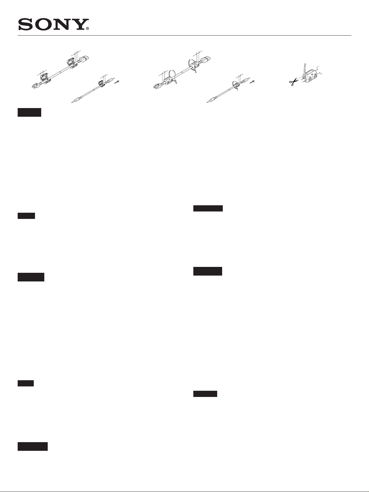
When attaching to the AC power cord
Attach the ferrite cores to both ends of the AC power cord and close the
1
ferrite cores until they click.
Wind the stopper round the cord so that the ferrite cores do not slide.
2
Tighten the stopper and cut the surplus.
3
When attaching to the cables
Attach the ferrite core to the end of the cable closer to this unit, closing it
1
until it clicks.
Wind the stopper round the cord so that the ferrite core does not slide.
2
Tighten the stopper and cut the surplus.
3
Notes
•When you connect this unit to various pieces of equipment using the RGB/
YUV connectors, use the specified cable.
SMF-400 (D-Sub 15P - 5 BNC), SMF-410 (D-Sub 15P - D-Sub 15P)
When you connect a cable to any of the terminals listed below, attach the
ferrite core provided before using the cable.
AUDIO (INPUT1), AUDIO (INPUT2)
•You are cautioned that this unit will not be in compliance with the EMC
limits unless the ferrite core is installed on the interconnecting wire.
Français
Pour la «Fixation du noyau de ferrite» de la page 16(FR),
suivre les instructions révisées ci-dessous.
Fixation du cordon d’alimentation secteur
Fixez les noyaux de ferrite aux deux extrémités du cordon d’alimentation
1
secteur et fermez-les jusqu’à ce qu’ils s’encliquettent.
Enroulez le système de fermeture autour du cordon de sorte que les noyaux
2
de ferrite ne glissent pas.
Serrez le système de fermeture et coupez le câble superflu.
3
Fixation des câbles
Fixez le noyau de ferrite à l’extrémité du câble la plus proche du présent
1
appareil. Fermez le noyau en appuyant jusqu’au déclic indiquant sa
fermeture.
Enroulez le système de fermeture autour du câble de manière à ce que le
2
noyau de ferrite ne glisse pas.
Serrez le système de fermeture et coupez le câble superflu.
3
Remarques
• Lors du raccordement de cet appareil à d’autres appareils via les
connecteurs RGB/YUV, utilisez le câble spécifié.
SMF-400 (D-Sub 15P - 5 BNC), SMF-410 (D-Sub 15P - D-Sub 15P)
Si vous raccordez un câble à l’une des bornes indiquées ci-dessous, fixez le
tore de ferrite fourni avant toute utilisation du câble.
AUDIO (INPUT1), AUDIO (INPUT2)
•Faites attention que cet appareil n’est pas conforme aux limites EMC sauf
si le tore de ferrite est installé sur le câble d’interconnexion.
Deutsch
Was das „Anbringen des Ferritkerns“ auf Seite 16(DE) betrifft,
so befolgen Sie die nachstehende revidierte Anweisung.
Anbringen am Netzkabel
Bringen Sie die Ferritkerne an den beiden Enden des Netzkabels an, und
1
schließen Sie sie, so dass sie mit einem Klicken einrasten.
Wickeln Sie den Stopper um das Kabel, damit die Ferritkerne nicht
2
verrutschen können.
Ziehen Sie den Stopper an, und schneiden Sie überstehende Teile ab.
3
Anbringen am Kabel
Bringen Sie den Ferritkern an dem Kabelende an, das sich näher an diesem
1
Gerät befindet, und schließen Sie ihn so, dass er mit einem Klicken
einrastet.
Wickeln Sie den Stopper um das Kabel, damit der Ferritkern nicht
2
verrutschen kann.
Ziehen Sie den Stopper an, und schneiden Sie überstehende Teile ab.
3
Hinweise
•Wenn Sie diese Einheit an verschiedene Geräte über die Anschlüsse RGB/
YUV anschließen, verwenden Sie das vorgeschriebene Kabel.
SMF-400 (D-Sub 15P - 5 BNC), SMF-410 (D-Sub 15P - D-Sub 15P)
Wenn ein Kabel an beliebige der unten aufgeführten Anschlüsse
angeschlossen wird, bringen Sie den mitgelieferten Ferritkern an, bevor Sie
das Kabel verwenden.
AUDIO (INPUT1), AUDIO (INPUT2)
• Beachten Sie bitte unbedingt, dass das Gerät die EMV-Richtlinien nur
erfüllt, wenn der Ferritkern am Verbindungskabel angebracht ist.
Sony Corporation © 2002 Printed in Japan
0-510-593-01(1)
Page 2
123
No superior a 10 mm (13/32 pulgadas)/
Non superiore a 10 mm/
10 mm 以内
No superior a 10 mm (13/32 pulgadas)/
Non superiore a 10 mm/
10 mm 以内
No superior a 10 mm (13/32 pulgadas)/
Non superiore a 10 mm/
10 mm 以内
No superior a 10 mm (13/32 pulgadas)/
Non superiore a 10 mm/
10 mm 以内
Español
En cuanto a la “Fijación del núcleo de ferrita” de la página
16(ES), siga la instrucción revisada siguiente.
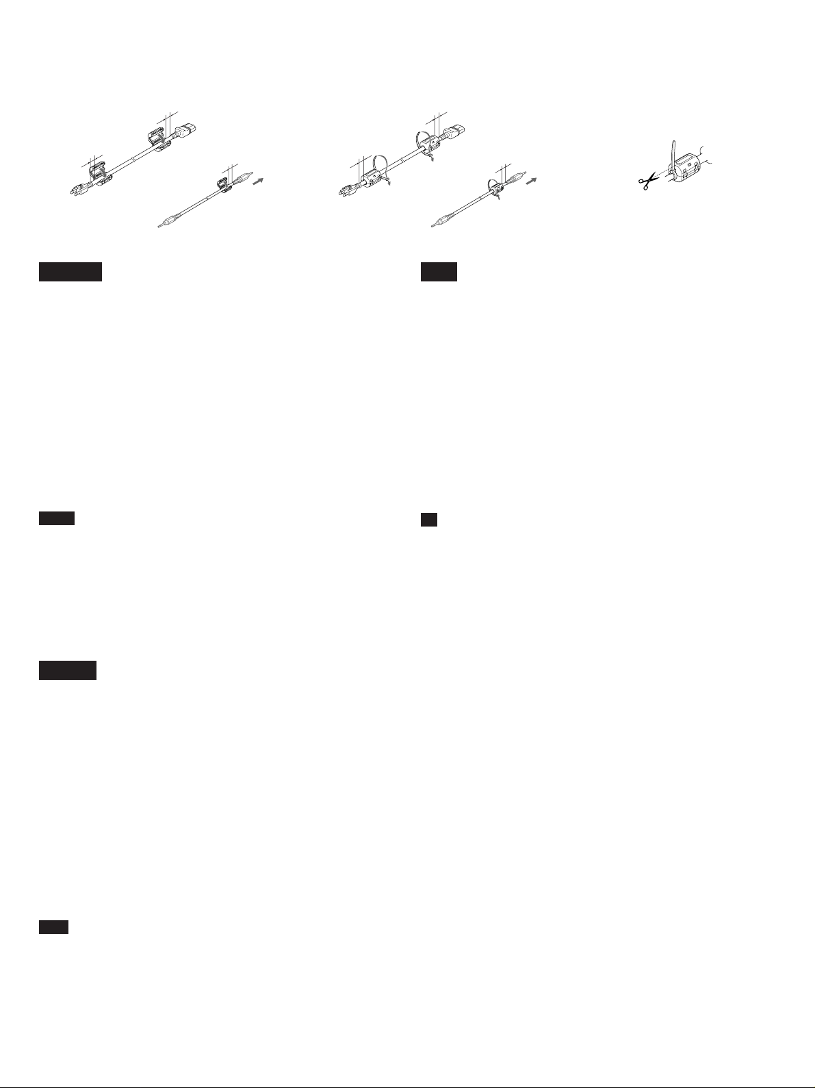
Al fijarlo al cable de alimentación de CA
Fije los núcleos de ferrita a ambos extremos del cable de alimentación de
1
CA y ciérrelos hasta que se oiga un “clic”.
Enrolle el tope alrededor del cable para que los núcleos de ferrita no
2
resbalen.
Apriete el tope y corte la parte superflua.
3
Al fijarlo a los cables
Fije el núcleo de ferrita al extremo del cable más próximo a la unidad y
1
ciérrelo hasta que oiga un “clic”.
Enrolle el tope alrededor del cable para que el núcleo de ferrita no resbale.
2
Apriete el tope y corte la parte superflua.
3
Notas
• Si conecta esta unidad a diferentes equipos mediante los conectores RGB/
YUV, utilice el cable especificado.
SMF-400 (D-Sub 15P - 5 BNC), SMF-410 (D-Sub 15P - D-Sub 15P)
Cuando conecte un cable a cualquiera de los terminales que se enumeran a
continuación, fije el núcleo de ferrita suministrado antes de utilizar dicho
cable.
AUDIO (INPUT1), AUDIO (INPUT2)
• Le advertimos de que esta unidad no cumplirá la normativa EMC a menos
que se instale el núcleo de ferrita en el cable de interconexión.
中文
关于第 16 页(CS)上“安装铁素体芯”的内容,请按照以
下说明进行修改。
连接至交流电源线时
将铁素体芯安装在交流电线的两端并合上铁素体芯直至发出喀嗒声。
1
将止动器绕在电线上使铁素体芯无法滑动。
2
紧固止动器并将多余部分剪断。
3
连接至电缆时
将铁素体芯连接于靠近本装置的电缆一端,直至其发出喀嗒声。
1
将电缆缠绕止动器使得铁素体芯不滑动。
2
拉紧制动器并剪除多余部份。
3
注
• 用 RGB/YUV 连接器将本机连接至装置的各部位时,请用专用电缆。
SMF-400(D-Sub 15P-5BNC)
SMF-410(D-Sub 15P-D-Sub 15P)
当将电缆连接至以下任一接口时,请在使用电缆前安装铁素体芯。
AUDIO(INPUT1)
AUDIO(INPUT2)
• 请注意,如果不将铁素体芯安装在连接线上,本装置不符合 EMC 限定。
Italiano
Riguardo la procedura “Applicazione del nucleo in ferrite”
riferita a pagina 16(IT), seguire le istruzioni corrette riportate
sotto.
Applicazione al cavo di alimentazione CA
Applicare i nuclei di ferrite a entrambe le estremità del cavo di
1
alimentazione CA, quindi chiudere i nuclei di ferrite finché non scattano in
posizione.
Collocare il fermo attorno al cavo in modo da bloccare i nuclei di ferrite.
2
Stringere il fermo, quindi tagliare la parte in eccedenza.
3
Applicazione ai cavi
Applicare il nucleo di ferrite all’estremità del cavo più vicina
1
all’apparecchio, quindi chiuderlo finché non scatta in posizione.
Collocare il fermo attorno al cavo in modo da bloccare il nucleo di ferrite.
2
Stringere il fermo, quindi tagliare la parte in eccedenza.
3
Note
•Per il collegamento del presente apparecchio ad altri dispositivi utilizzando i
connettori RGB/YUV, utilizzare il cavo specificato.
SMF-400 (D-Sub 15P - 5 BNC), SMF-410 (D-Sub 15P - D-Sub 15P)
Se ad uno dei terminali elencati di seguito viene collegato un cavo, prima di
utilizzarlo applicare il nucleo di ferrite fornito.
AUDIO (INPUT1), AUDIO (INPUT2)
• Si noti che il presente apparecchio è conforme ai limiti EMC solo se nel
cavo di collegamento è installato il nucleo di ferrite.
 Loading...