

Sony PFM-500A2WU User Manual
3-866-789-02(1)
Flat Panel Monitor
Operating Instructions
Mode d’emploi
Bedienungsanleitung
Manual de instrucciones
Istruzioni per l’uso
取扱説明書
お買い上げいただきありがとうございます。
この取扱説明書には、事故を防ぐための重要な注意事項と製品の取り扱
いかたを示しています。この取扱説明書をよくお読みのうえ、製品を安
全にお使いください。お読みになったあとは、いつでも見られるところ
に必ず保管してください。
警告
電気製品は安全のための注意事項を守らないと、
火災や人身事故になることがあります。
EN
F
D
ES
I
J
PFM-500A2WU
PFM-500A2WE
PFM-500A2WJ
1999 by Sony Corporation
WARNING
Owner’s Record
The model and serial numbers are located on the rear.
Record the model and serial numbers in the spaces provided
below. Refer to these numbers whenever you call upon your
Sony dealer regarding this product.
Model No.
To prevent fire or shock hazard, do not
expose the unit to rain or moisture.
For the customers in the U.S.A.
This equipment has been tested and found to comply with
the limits for a Class A digital device, pursuant to Part 15 of
the FCC Rules. These limits are designed to provide
reasonable protection against harmful interference when the
equipment is operated in a commercial environment. This
equipment generates, uses, and can radiate radio frequency
energy and, if not installed and used in accordance with the
instruction manual, may cause harmful interference to radio
communications. Operation of this equipment in a residential
area is likely to cause harmful interference in which case the
user will be required to correct the interference at his own
expense.
You are cautioned that any changes or modifications not
expressly approved in this manual could void your authority
to operate this equipment.
For the customers in Canada
This class A digital apparatus complies with Canadian ICES-
003.
For the customers in Europe
This is a Class A product. In a domestic environment, this
product may cause radio interference in which case the user
may be required to take adequate measures.
Serial No.
For PFM-500A2WE users
THIS APPARATUS MUST BE EARTHED
IMPORTANT
The wires in this mains lead are coloured in accordance with
the following code:
Green-and-yellow : Earth
Blue : Neutral
Brown : Live
As the colours of the wires in the mains lead of this
apparatus may not correspond with the coloured markings
identifying the terminals in your plug proceed as follows:
The wire which is coloured green-and-yellow must be
connected to the terminal in the plug which is marked with
the letter E or by the safety earth symbol Y or coloured
green or green-and-yellow.
The wire which is coloured blue must be connected to the
terminal which is marked with the letter N or coloured black.
The wire which is coloured brown must be connected to the
terminal which is marked with the letter L or coloured red.
Voor de klanten in Nederland
Bij dit produkt zijn batterijen geleverd.
Wanneer deze leeg zijn, moet u ze niet
weggooien maar inleveren als KCA.
The socket-outlet should be installed near the equipment
and be easily accessible.
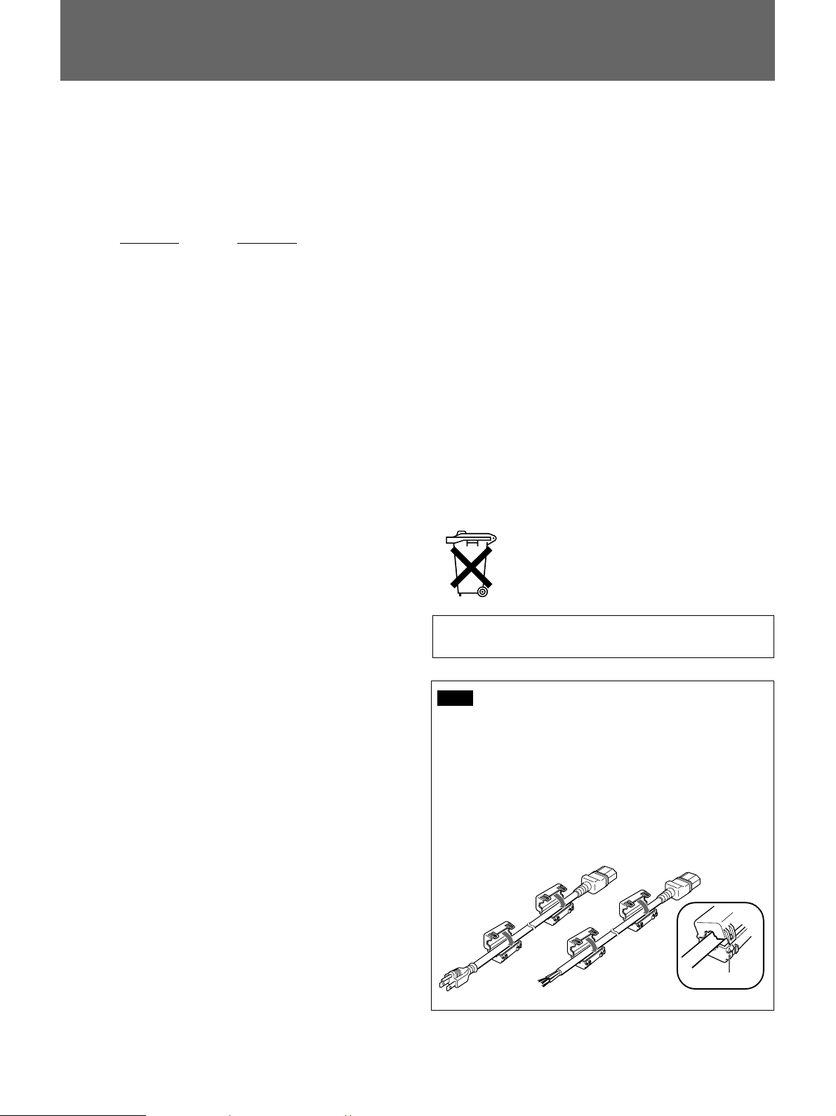
Note
When you connect a computer to this monitor, attach
the supplied ferrite cores. If you do not do this, this
monitor will not conform to mandatory FCC/IC/CE
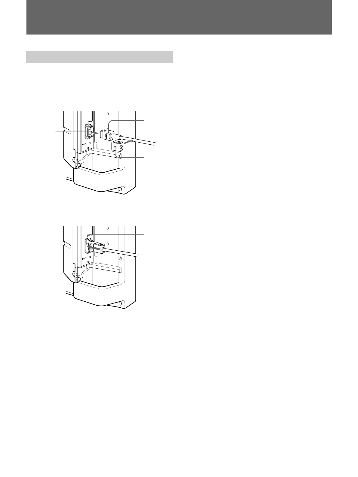
(EN55022) standards.
Attaching the ferrite cores
Set the ferrite cores on the both ends of the AC
power cord. Close the lid tightly until the clamps
click.
22 (EN)
or
Clamps

Table of Contents
Precautions............................................................... 4 (EN)
Features .................................................................... 5 (EN)
Location and Function of Parts and Controls ....... 6 (EN)
Front / Sides ............................................................ 6 (EN)
Control Panel........................................................... 8 (EN)
Right Connector Panel ............................................ 9 (EN)
Left Connector Panel............................................. 11 (EN)
Remote Commander RM-921 ............................... 12 (EN)
Installation .............................................................. 14 (EN)
Using the Retractable Feet .................................... 14 (EN)
Caution .................................................................. 15 (EN)
Connections ........................................................... 16 (EN)
Connecting the AC Power Cord............................ 16 (EN)
Connection Example ............................................. 17 (EN)
Using On-screen Menus ........................................ 18 (EN)
Operating Through Menus .................................... 18 (EN)
Menu Guide........................................................... 18 (EN)
Watching the Picture ............................................. 22 (EN)
Switching the Picture ............................................ 22 (EN)
Watching a Still Picture ........................................ 22 (EN)
Input Signal and Monitor Status Information
Display ............................................................. 22 (EN)
Adjusting the Picture ............................................. 24 (EN)
Adjusting the Contrast, Brightness, Chroma, and
Phase ................................................................ 24 (EN)
Emphasizing the Contrast of the Picture
(Picture AGC Function) ................................... 24 (EN)
Restoring the PIC CONTROL Menu Items to Original
Settings............................................................. 25 (EN)
Zooming, Resizing, and Positioning the Picture. 26 (EN)
Resizing the Picture............................................... 26 (EN)
Adjusting the Picture Position............................... 26 (EN)
Zooming Up the Picture ........................................ 27 (EN)
Restoring the Original Picture Size and Position .. 27 (EN)
Using the Memory .................................................. 28 (EN)
Storing the Current Condition............................... 28 (EN)
Calling Up the Stored Condition........................... 28 (EN)
Turning Off the Power Automatically When There Is No
Input Signal (Power Saving Function)........... 30 (EN)
Selecting the On-screen Language ...................... 31 (EN)
Self-diagnosis Function ........................................ 31 (EN)
Operating a Specific Monitor With the Remote
Commander...................................................... 32 (EN)
Using the Other Remote Commander .................. 33 (EN)
Specifications......................................................... 34 (EN)
EN
English
3 (EN)

Precautions
On safety
•Operate the unit on 100 to 120 V AC or 220 to 240 V
AC.
•The nameplate indicating operating voltage, power
consumption, etc. is located on the rear.
•Should any solid object or liquid fall into the cabinet,
unplug the unit and have it checked by qualified
personnel before operating it any further.
•Unplug the unit from the wall outlet if it is not to be
used for several days or more.
•To disconnect the AC power cord, pull it out by
grasping the plug. Never pull the cord itself.
•When the unit is installed on the floor, be sure to use
the retractable feet.
On installation
•Allow adequate air circulation to prevent internal
heat build-up. Do not place the unit on surfaces (rugs,
blankets, etc.) or near materials (curtains, draperies)
that may block the ventilation holes.
•Do not install the unit in a location near heat sources
such as radiators or air ducts, or in a place subject to
direct sunlight, excessive dust, mechanical vibration
or shock.
•When you install multiple equipment with the unit,
the following, such as Remote Commander’s
malfunction, noisy picture, noisy sound, may occur
depending on the position of the unit and other
equipment.
On repacking
Do not throw away the carton and packing materials.
They make an ideal container in which to transport the
unit. When shipping the unit to another location,
repack it as illustrated on the carton.
If you have any questions about this unit, contact your
authorized Sony dealer.
On PDP (Plasma Display Panel)
•There may be some tiny black points and/or bright
points on the PDP. These points are normal.
•Do not display a same still image on the screen for
long, consecutive time. Otherwise, the afterimage
may appear on a part of a panel since the brightness
of the part of the picture becomes high due to the
consecutive display of the picture. Use the screen
saver eventually to equalize the screen display.
On cleaning
To keep the unit looking brand-new, periodically clean
it with a mild detergent solution. Never use strong
solvents such as thinner or benzine, or abrasive
cleansers since these will damage the cabinet. As a
safety precaution, unplug the unit before cleaning it.
44 (EN)
Features
The PFM-500A2W series are 16:9 42-inch flat panel
monitor adopting the PDP (Plasma Display Panel) and
accepts various types of signals with the built-in scan
converter.
Improved image quality
Higher image quality is gained with the new PDP –
improving brightness more than conventional
monitors. An anti-glare filter panel reduces screen
reflection.
Scan converter – Improved performance
The monitor has a high performance scan converter.
Using a unique algorithm, the monitor processes
signals in a wide range of formats – Video, HDTV,
PC, etc. Signal process capability has been improved
25% more than conventional monitors. The monitor
can process signals up to 100 kHz in the horizontal
frequencies.
Reduced noise
Optimization of the internal cooling system further
reduces the noise level.
Other features
•Three dimensional comb filter for NTSC Y/C
separation.
•Line correlation comb filter for PAL Y/C separation.
•Up to x4 zooming.
•Accepts infrared or wired Sony Remote Commanders
using SIRCS code.
•Three sets of video inputs with audio inputs: one
composite video or Y/C inputs, one RGB input, and
one RGB/component input.
•Displays the HDTV signal with tri-level sync signal.
•Memory function for storage of up to five picture
settings.
•Automatic input signal detection with indication.
1)
•Windows95/98
PnP (Plug and Play) compatible.
•On-screen display in five languages for user-friendly
access.
•Power Saving function.
•Self-diagnosis function.
•Picture AGC function — this function automatically
adjusts and improves the contrast when a low
intensity signal is input.
•ID control
•On-screen menu for various adjustments and settings
•Control-S connector
•Remote (RS-232C) connector (mini DIN 8-pin)
Warning on power connection
Use a proper power cord for your local power supply.
United States, Continental United Kingdom, Ireland, Japan
Canada Europe Australia, New Zealand
Plug type VM0033B COX-07 636 — VM1296
Female end VM0113 COX-02 VM0310B VM0303B VM1313
Cord type SJT H05VV-F CEE (13) 53rd (O.C) HVCTF
Minimum cord set rating 13A/125V 10A/250V 10A/250V 10A/125V
Safety approval UL/CSA VDE VDE DENTORI
.........................................................................................................................................................................................................
1) Windows95/98 is a registered trademark of the Microsoft Corporation.
5 (EN)
Location and Function of Parts and Controls
34
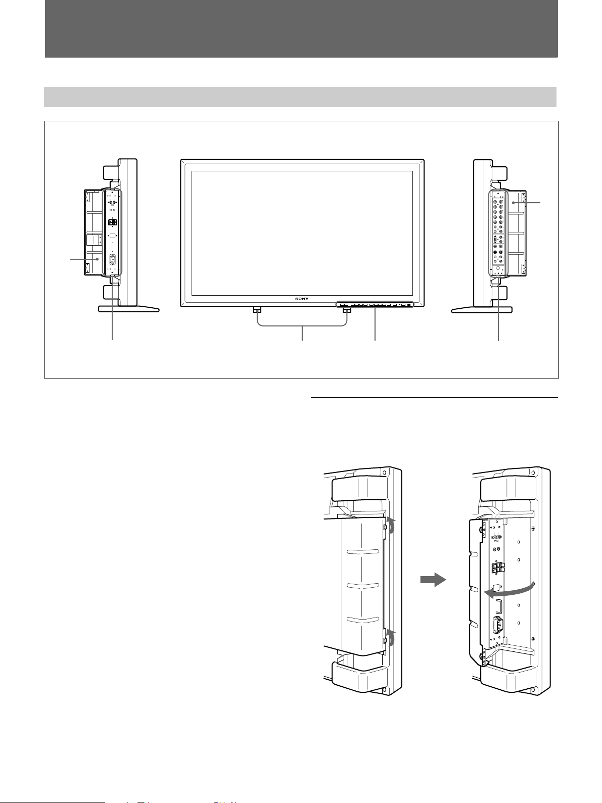
Front / Sides
Left side Front
1
2
1 Left panel cover
Open it when using the left connector panel.
You can install the Remote Commander in the back of
this cover.
For details on opening the panel cover, see the right on this
page.
Right side
6
5
To open the panel cover
Loosen the screws counterclockwise and open the
cover.
2 Left connector panel
For details on the left connector panel, see “Left Connector
Panel” on page 11(EN).
3 Retractable feet
Use for setting the monitor on the floor.
For details on using the retractable feet, see “Using the
Retractable Feet” on page 14(EN).
4 Control panel
For details on the control panel, see “Control Panel” on
page 8(EN).
5 Right connector panel
For details on the right connector panel, see “Right
Connector Panel” on page 9(EN).
6 Right panel cover
Open it when using the right connector panel.
For details on opening the panel cover, see the right on this
page.
66 (EN)
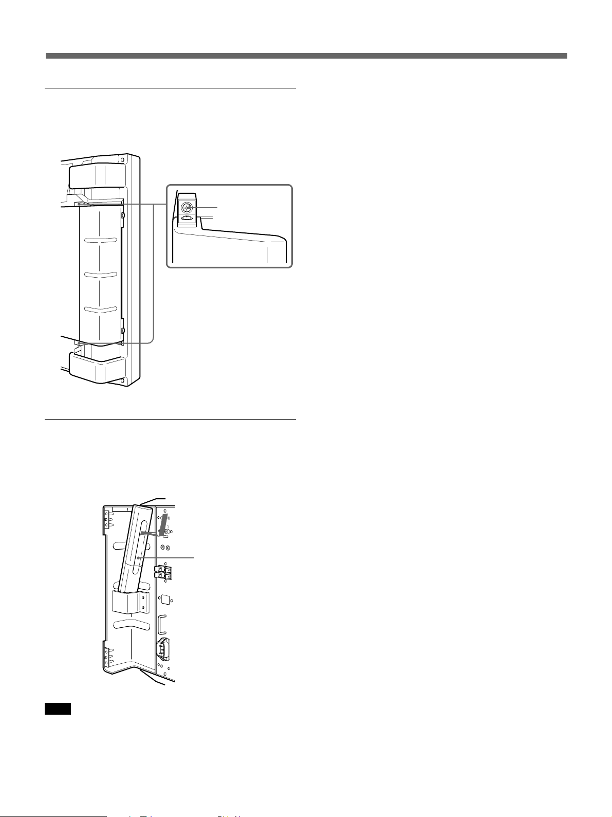
To take off the panel cover
Loosen the screws as illustrated below and take off the
panel cover.
Screws
To install the Remote Commander in the
panel cover
Install the Remote Commander in the back of the left
panel cover as illustrated below.
Remote
Commander
Note
When housing the Remote Commander, make sure that
the top of the Remote Commander faces upward and
rear faces outside.
7 (EN)
Location and Function of Parts and Controls
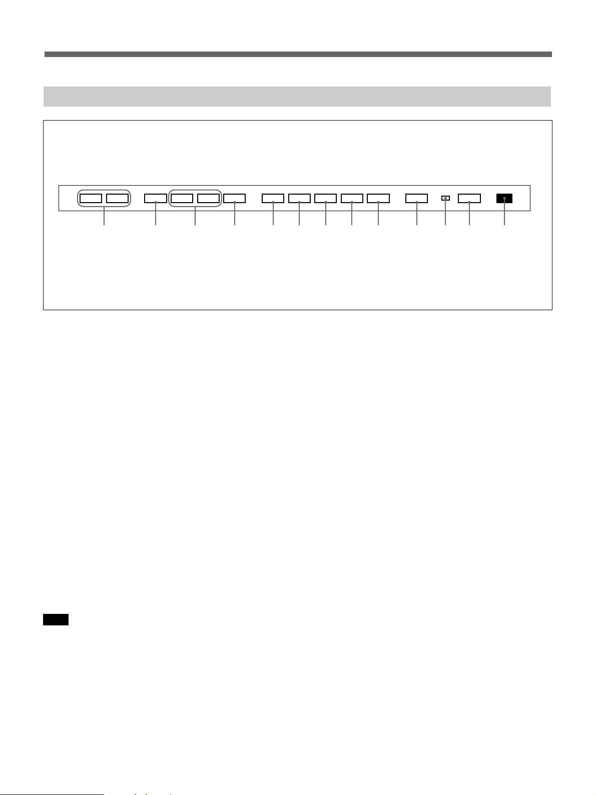
Control Panel
VOL – VOL + MENU ENT RGB1 YUV RGB2 LINE Y/C CTRL
!£ !™ !¡ 0 98765 4 32 1
.>
1 Remote control detector
Receives the beam from the Remote Commander.
2 u (standby) switch/u (standby) indicator
Press to turn the monitor on. Press again to go back to
the standby mode.
The u (standby) indicator lights up in red in the
standby mode.
When the u indicator flashes, see “Self-diagnosis
Function” on page 31(EN).
3 Power indicator
Lights up when the monitor is turned on.
Flashes in the power saving mode.
For details on the power saving mode, see “Turning Off the
Power Automatically When There Is No Input Signal (Power
Saving Function)” on page 30(EN).
u
6 LINE button
Select the signal input from the VIDEO IN connector
in the LINE connectors.
7 RGB2 button
Select the signal input from the RGB2 connectors.
8 YUV button
Select the component signal input from the RGB1
connectors.
9 RGB1 button
Select the RGB signal input from the RGB1
connectors.
0 ENT (enter) button
Press to select the desired item in a menu.
4 CTRL (control) button
To operate the buttons on the control panel, first press
this button. Then the buttons light up or flash that show
they can be operated. Press again to deactivate them.
Note
The buttons (except for u (standby) switch 2) on the
control panel do not function if you do not press the
CTRL button first.
5 Y/C button
Select the signal input from the Y/C IN jack in the
LINE connectors.
88 (EN)
!¡ >/. buttons
Press to move the cursor (z) to an item or to adjust
value in a menu.
!™ MENU button
Press to make the menu appear.
!£ VOL (volume) +/– buttons
Press the + button to increase the volume, or the –
button to decrease the volume.
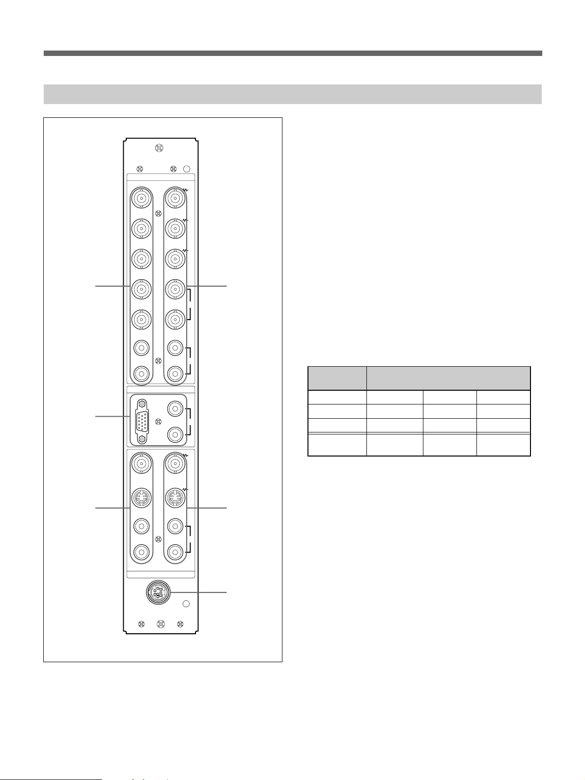
Right Connector Panel
RGB 1
IN OUT
R
R-Y
G
Y
B
B-Y
1
HD/
COMP
VD
SYNC
4
1 RGB1 IN connectors
R (R-Y)/G (Y)/B (B-Y) IN (BNC-type): Input the
analog RGB signal or component signal. Connect
to the RGB signal or component (Y/B-Y/R-Y)
signal output of a computer or video equipment.
This unit also accepts the HD analog component
B/PR) signal. Input the PB signal to the B (B-
(Y/P
Y) IN connector and P
R signal to the R (R-Y) IN
connector.
HD/COMP IN (BNC-type): Input the H sync signal
or composite sync signal. Connect to the H sync
signal or composite sync signal output of a
computer or video equipment.
VD IN (BNC-type): Input the V sync signal.
Connect to the V sync signal output of a computer
or video equipment.
2
3
L
R
RGB 2
RGB IN
L
R
VIDEO
Y/C
L
R
IN OUT
LINE
REMOTE
(RS-232C)
AUDIO
AUDIO IN
AUDIO
5
6
External sync signal is selected automatically. See the
priority chart below.
Input Input sync signals
connector
HD/COMP IN H Sync Comp Sync —
VD IN V Sync — —
G(Y) IN Sync on G Sync on G Sync on G
Sync signals H Sync Comp Sync Sync on G
to be selected V Sync
AUDIO IN (L/R) (phono type): Input the audio
signal. Connect to the audio output of a computer
or video equipment. Connect to the channel L
when the audio signal is monaural.
2 RGB2 IN connectors
RGB IN (D-sub 15-pin): Connect to the RGB signal
output of a computer.
AUDIO IN (L/R) (phono type): Input the audio
signal. Connect to the audio output of a computer.
Connect to the channel L when the audio signal is
monaural.
(Continued)
9 (EN)

Location and Function of Parts and Controls
3 LINE IN connectors
VIDEO IN (BNC-type): Connect to the composite
video signal output of the video equipment.
Y/C IN (Mini DIN 4-pin): Connect to the Y/C signal
output of the video equipment.
AUDIO IN (L/R) (phono type): Connect to the
audio output of the video equipment. Connect to
the channel L when the audio signal is monaural.
4 RGB1 OUT connectors
These connectors are used as loop-through outputs of
the RGB1 IN connectors 1.
When the plug is connected to the RGB OUT
connectors, the 75-ohms termination of the RGB IN
connectors is released, and the signal input to the RGB
IN connectors is output from the these connectors.
R (R-Y)/G (Y)/B (B-Y) OUT (BNC-type): Loop-
through outputs of the RGB IN connectors.
Connect to the RGB signal or component (Y/B-Y/
R-Y) signal input of another monitor.
HD/COMP OUT (BNC-type): Loop-through output
of the HD/COMP IN connector. Connect to the H
sync signal or composite sync signal input of
another monitor.
VD OUT (BNC-type): Loop-through output of the
VD IN connector. Connect to the V sync signal
input of another monitor.
5 LINE OUT connectors
These connectors are used as loop-through outputs of
the LINE IN connectors 3.
When the plug is connected to the VIDEO OUT
connector or Y/C OUT jack, the 75-oms termination of
the VIDEO IN connector or Y/C IN jack is released,
and the signal input to the VIDEO IN or Y/C IN jack is
output from the VIDEO OUT connector or Y/C OUT
jack.
VIDEO OUT (BNC-type): Connect to the
composite video signal input of another monitor
or video equipment.
Y/C OUT (Mini DIN 4-pin): Connect to the Y/C
signal input of another monitor or video
equipment.
AUDIO OUT (L/R) (phono type): Loop-through
outputs of the AUDIO IN jacks. Connect to the
audio inputs of another monitor or video
equipment.
6 REMOTE (RS-232C) connector (mini DIN 8-
pin)
This connector allows remote control of the monitor
using the RS-232C protocol. For details, see your
authorized Sony dealer.
Note
The HD/COMP OUT and VD OUT connectors are
high impedance outputs.
When using these outputs, connect a monitor with
high impedance sync input connector, or the picture
might be oscillated or disappeared because of the
sync signal level mismatch.
AUDIO OUT (L/R) (phono type): Loop-through
outputs of the AUDIO IN jacks. Connect to the
audio inputs of another monitor.
1010 (EN)
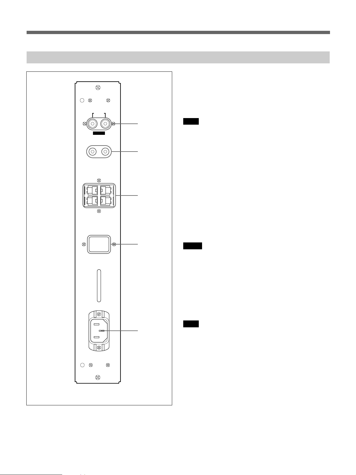
Left Connector Panel
MONITOR OUT
AUDIO
RL
VARIABLE
CONTROL S
IN
SPEAKERS
+
R–
SERVICE CODE
OUT
(6-16 Ω)
1 MONITOR OUT AUDIO (L/R) jacks (phono
type)
Output the signal input from the AUDIO IN jacks.
Connect to the audio inputs of an audio amplifier (not
supplied).
1
Note
These jacks are variable outputs. Set the volume to
maximum position to set the output level to
500 mVrms.
2
2 CONTROL S IN/OUT jacks (mini jacks)
Connect to the CONTROL S jacks of video equipment
or another monitors. Then you can simultaneously
+
L
–
3
control all equipment with a single Remote
Commander.
To control equipment by aiming the supplied Remote
Commander to the remote control detector of the
monitor, connect the CONTROL S OUT jack of the
monitor and the CONTROL S IN jack of other
equipment.
8.8.
AC IN
4
5
Notes
•If you connect the CONTROL S IN jack to the other
equipment’s CONTROL S OUT jack, you cannot
operate the monitor with the Remote Commander.
•You can use the stereo cable with mini plug instead
of the control S cable.
3 SPEAKERS L/R terminals
Connect to speakers with 6 to 16 ohms impedance.
Note
Do not connect the speaker’s cord to the monitor and
to an amplifier simultaneously, or an excessive electric
current might flow from the amplifier and damage the
monitor.
4 SERVICE CODE indicator
This indicator is only for qualified personnel.
5 ⁄AC IN socket
Connect the supplied AC power cord to this socket and
to a wall outlet. Once you connect the AC power cord,
the monitor turns to standby mode.
11 (EN)
Location and Function of Parts and Controls
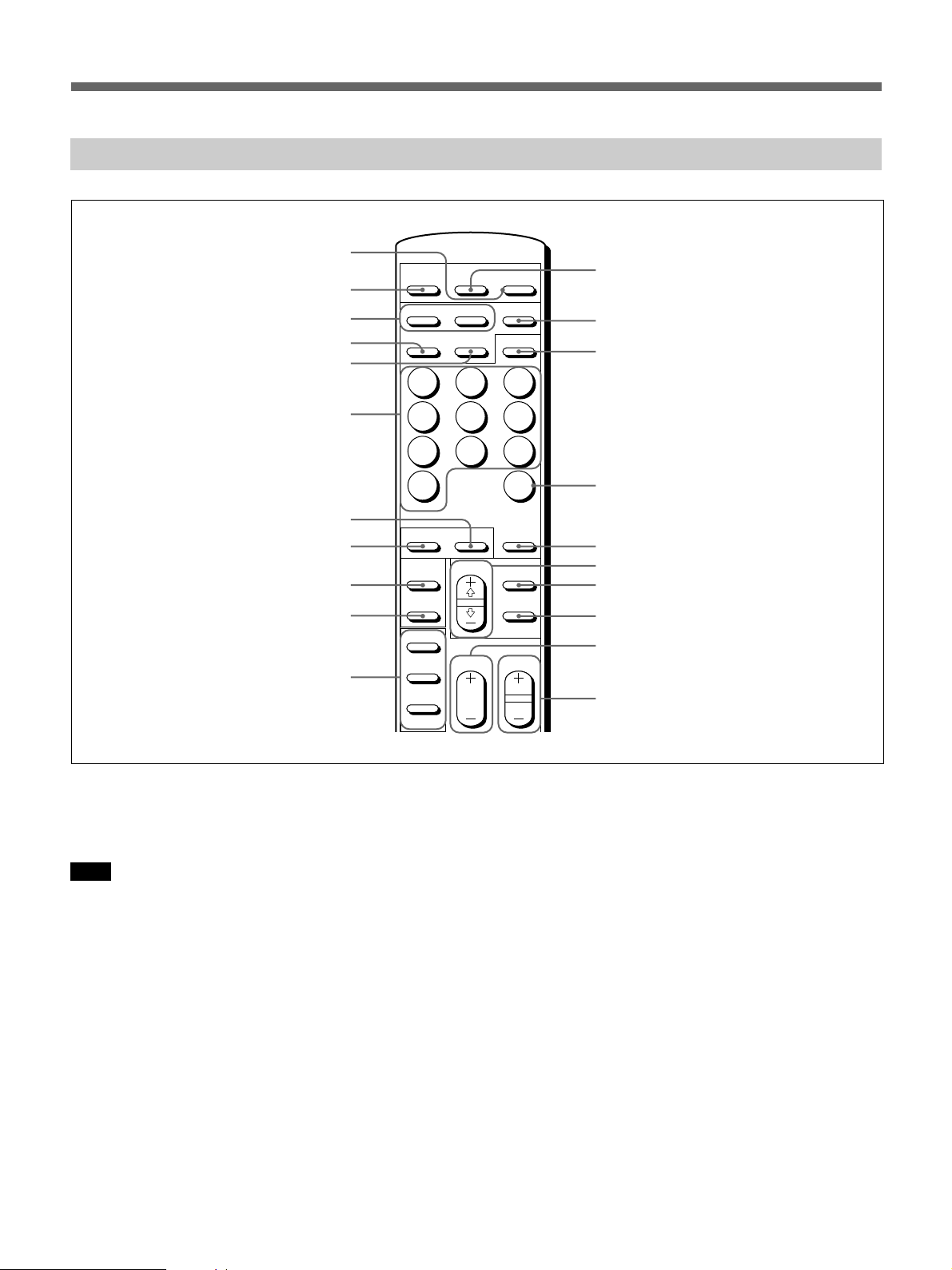
Remote Commander RM-921
1
MUTING
2
3
4
5
DISPLAY
RGB1
LINE
1
RGB2
Y/C
2
POWER
YUV
MTS/MPX
3
!™
!£
!¢
6
4
7
10/0
7
8
9
0
!¡
STILL
POWER
ON
OFF
ON
SET
OFF
ID MODE
1 POWER switch
Press to turn on the monitor. Press again to go back to
the standby mode.
Note
When using multiple monitors, press this switch to
turn monitors which are already on into the standby
mode, or turn on monitors which are in the standby
mode.
2 MUTING button
Press to mute the sound. Press this button again or
press the VOL (volume) +/– button to obtain the sound
again.
3 RGB1/RGB2 buttons
Select the signal input from the RGB1 or RGB2
connectors.
5
8
ZOOM
SELECT
VOL
6
9
CH
DEGAUSS
MENU
ENTER
CH
!∞
!§
!¶
!•
!ª
@º
@¡
4 LINE button
Selects the signal input from the VIDEO IN connector
in the LINE connectors.
5 Y/C button
Selects the signal input from the Y/C IN jack in the
LINE connectors.
6 Number buttons
Press to select the index number.
7 ZOOM button
Adjusts the zoom. Each time you press the ZOOM
button, the picture is magnified by two, three, and four
times respectively.
8 STILL button
Freezes a picture on the monitor screen. Press again to
resume normal screen.
1212 (EN)
9 POWER ON switch
Press to turn on the monitor. When you use multiple
monitors, you can use this switch instead of the
POWER switch 1 not to affect another monitor which
is already turned on.
0 POWER OFF switch
Press to turn the monitor into the standby mode. When
you use multiple monitors, you can use this switch
instead of the POWER switch 1 not to affect another
monitor which are in the standby mode.
!¡ ID MODE (ON/SET/OFF) buttons
Press the ON button to make an index number appear
on the screen. Then press the index number of the
monitor you want to operate and press the SET button.
After you finish the operation, press the OFF button to
return to the normal mode.
!™ DISPLAY button
Displays the input signal information on the top of the
monitor screen. Press again to clear it.
!£ YUV button
Selects the component signal input from the RGB1
connectors.
!¢ MTS/MPX button
This button does not operate with the monitor.
!∞ CH button
This button does not operate with the monitor.
!§ DEGAUSS button
This button does not operate with the monitor.
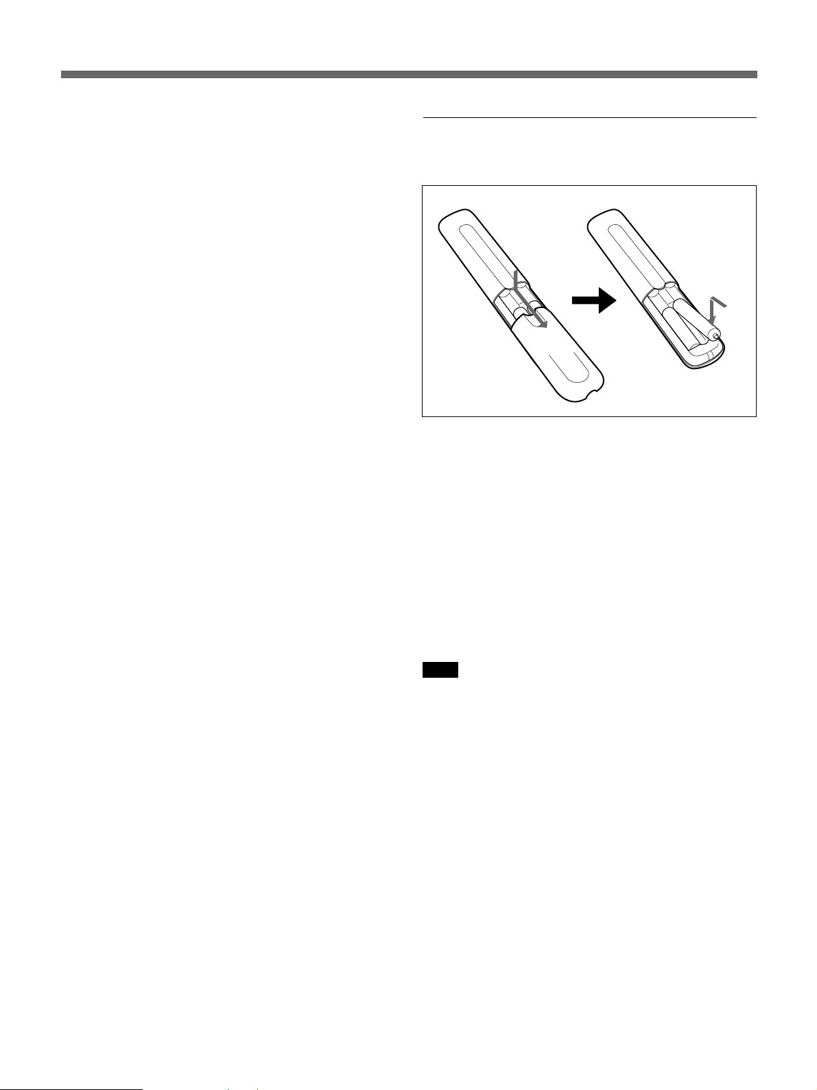
Installing batteries
Insert two size AA (R6) batteries in correct polarity.
Be sure to install
the negative ’
end first
}
]
]
}
•In normal operation, batteries will last up to half a
year. If the Remote Commander does not operate
properly, the batteries might be exhausted. Replace
them with new ones.
•To avoid damage from possible battery leakage,
remove the batteries if you do not plan to use the
Remote Commander for a fairly long time.
When the Remote Commander does not work
Check that the u indicator lights up. The Remote
Commander operates the monitor only when the
monitor is turned on, or it is in the standby mode.
Note
If you connect the cable to the CONTROL S IN jack
on the side of the monitor, you cannot operate the
monitor with the Remote Commander.
!¶ SELECT +>/–. buttons
Press to move the cursor (z) to an item or to adjust
value in a menu.
!• MENU button
Press to make the menu appear.
!ª ENTER button
Press to select the desired item in a menu.
@º VOL +/– buttons
Press the + button to increase the volume, or the –
button to decrease the volume.
@¡ CH +/– buttons
This button does not operate with the monitor.
13 (EN)
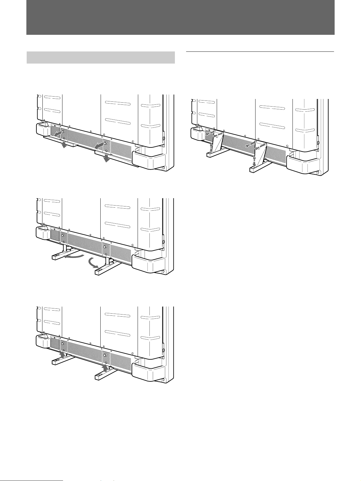
Installation
Using the Retractable Feet
1 Pull out the knobs and pull down the retractable
feet.
2 Turn the retractable feet outward.
To fix the retractable feet
When the unit is installed on the floor, be sure to fix
the retractable feet.
Install the foot support brackets as illustrated below.
3 Push in the retractable feet and lock.
1414 (EN)
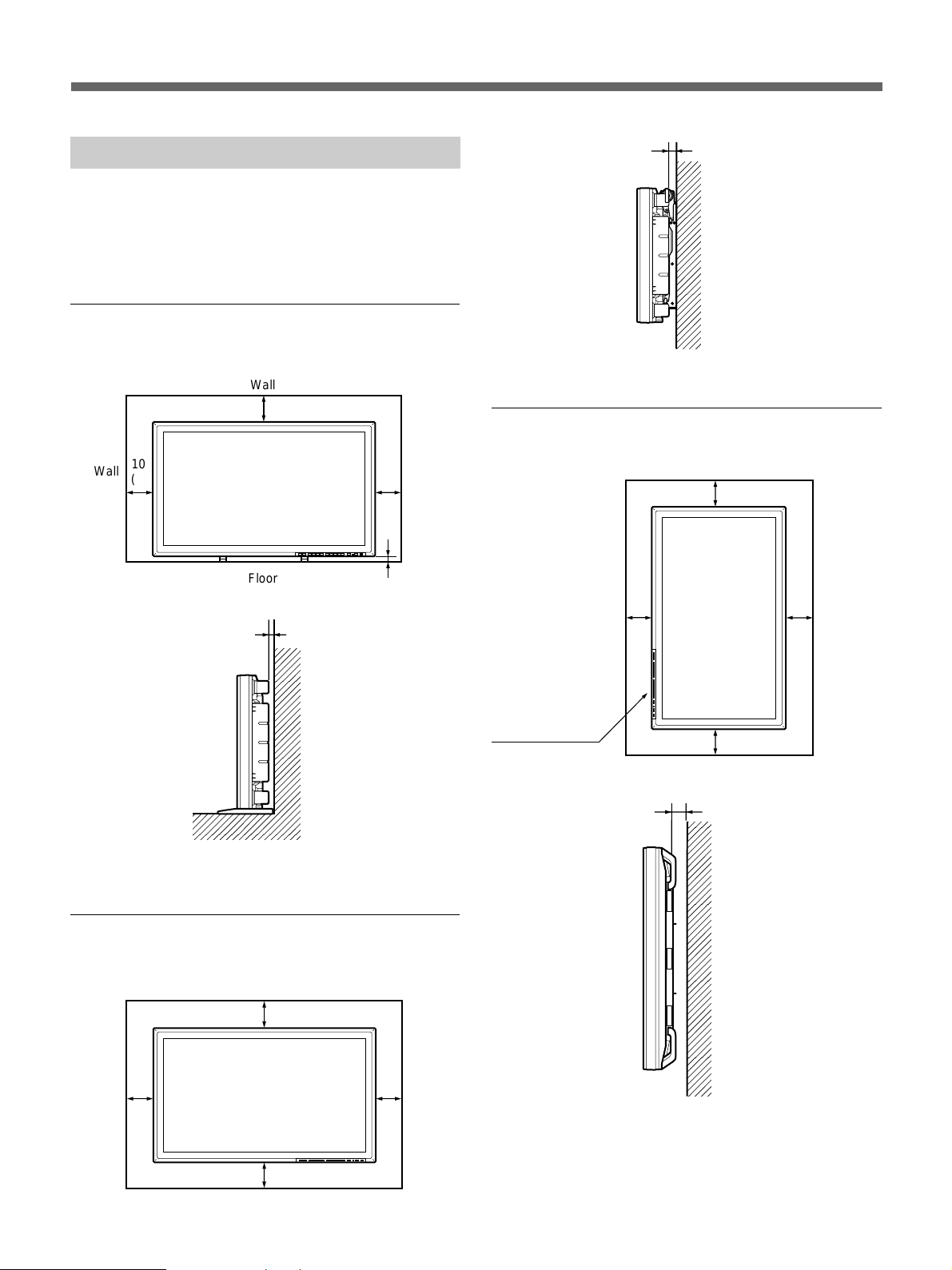
Caution
•When you install the monitor, make sure there is
more space than that shown in the figure below.
•The ambient temperature must be 0°C – +35°C (32°F
– 95°F).
When using the retractable feet
Side
3.5 (1 7/16)
Wall
Front
Wall
Side
10
(4)
Wall
Floor
20 (7 7/8)
5.5 (2 1/4)
Wall
10
(4)
2.5 (1)
Wall
Units: cm (inches)
Hooked on the wall: Vertically
Front
Make sure that the
control section is at
the bottom.
Side
Wall
20
(7 7/8)
Wall
10 (4)
10 (4)
Wall
5 (2)
25
(9 7/8)
Wall
Floor
Units: cm (inches)
When using the mounting bracket
Front
Wall
25 (9 7/8)
10
Wall
(4)
25 (9 7/8)
Wall
10
(4)
Wall
Wall
Units: cm (inches)
15 (EN)
Connections
Connecting the AC Power Cord
1 Plug the power cord into the AC IN socket. Then,
attach the AC plug holder (supplied) to the AC
power cord.
AC power
cord
AC IN
socket
AC plug
holder
2 Slide the AC plug holder over the cord until it
connects to the AC IN socket cover.
AC IN
socket
cover
To remove the AC power cord
Squeeze the upper and lower sides and pull out the AC
plug holder.
1616 (EN)
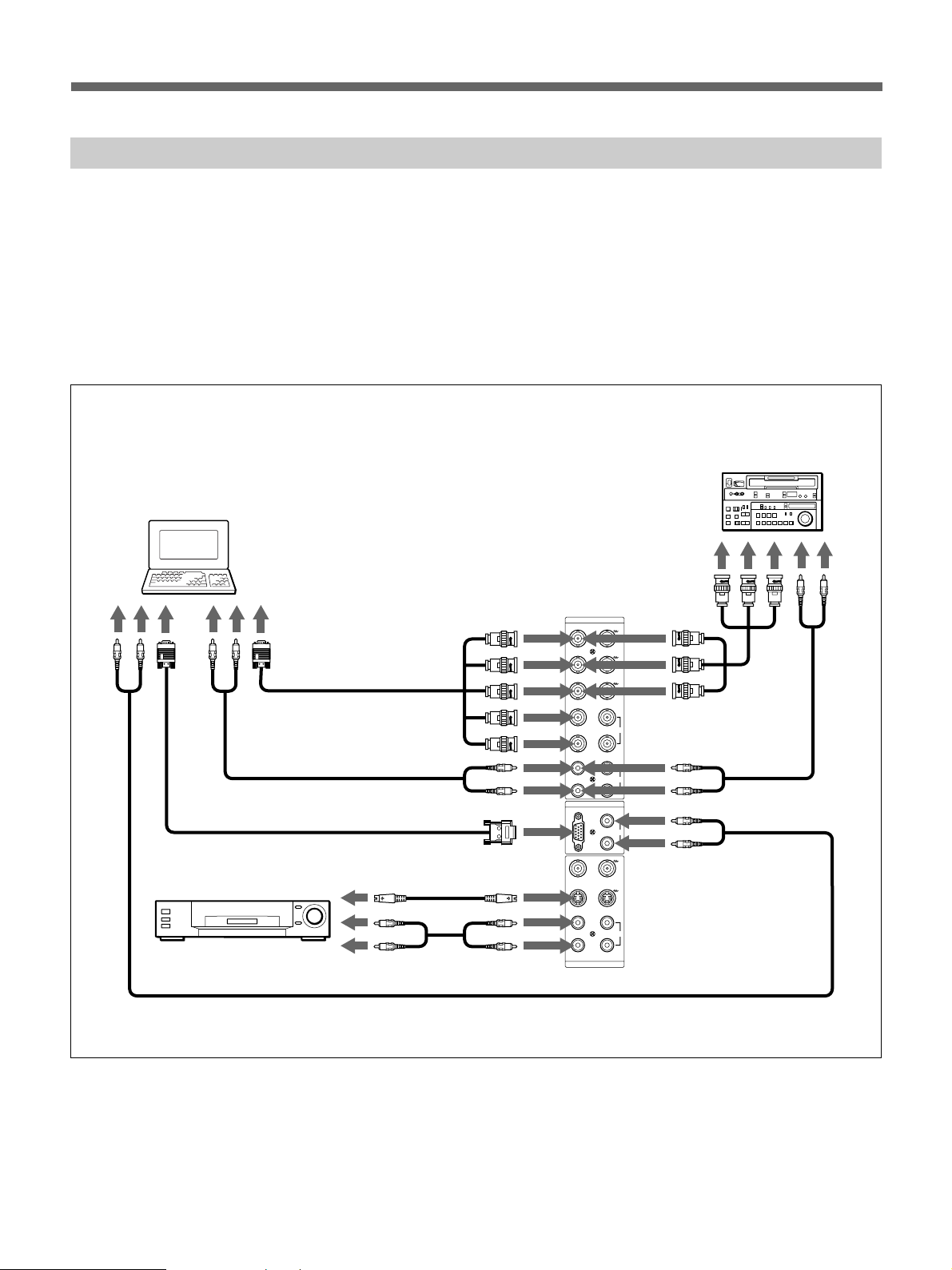
Connection Example
Before you get started
•First make sure that the power to each piece of
equipment is turned off.
•Use connecting cables suitable for the equipment to
be connected.
•The cable connectors should be fully inserted into the
jacks. A loose connection may cause hum and other
noise.
Computer
* to R(R-Y)/G(Y)/
B(B-Y), HD/COMP,
VD IN
to AUDIO IN
to RGB IN
to video
output
to audio
output
to audio
output
to video
output
to video
output
to audio
output
VCR, laser disc player, game
machine, etc.
•To disconnect the cable, pull out by grasping the
plug. Never pull the cable itself.
•Read the instruction manual of the equipment to be
connected.
Betacam SP video
cassette recorder
to component or
RGB signal
output
RGB 1
IN OUT
R
R-Y
G
Y
B
B-Y
* to R(R-Y)/G(Y)/
B(B-Y) IN
to AUDIO IN
to AUDIO IN
to Y/C or
VIDEO IN
to AUDIO IN
HD/
COMP
VD
RGB 2
RGB IN
VIDEO
Y/C
IN OUT
LINE
SYNC
L
AUDIO
R
L
AUDIO IN
R
L
AUDIO
R
to audio
output
* cannot be used at the same time.
17 (EN)
Using On-screen Menus
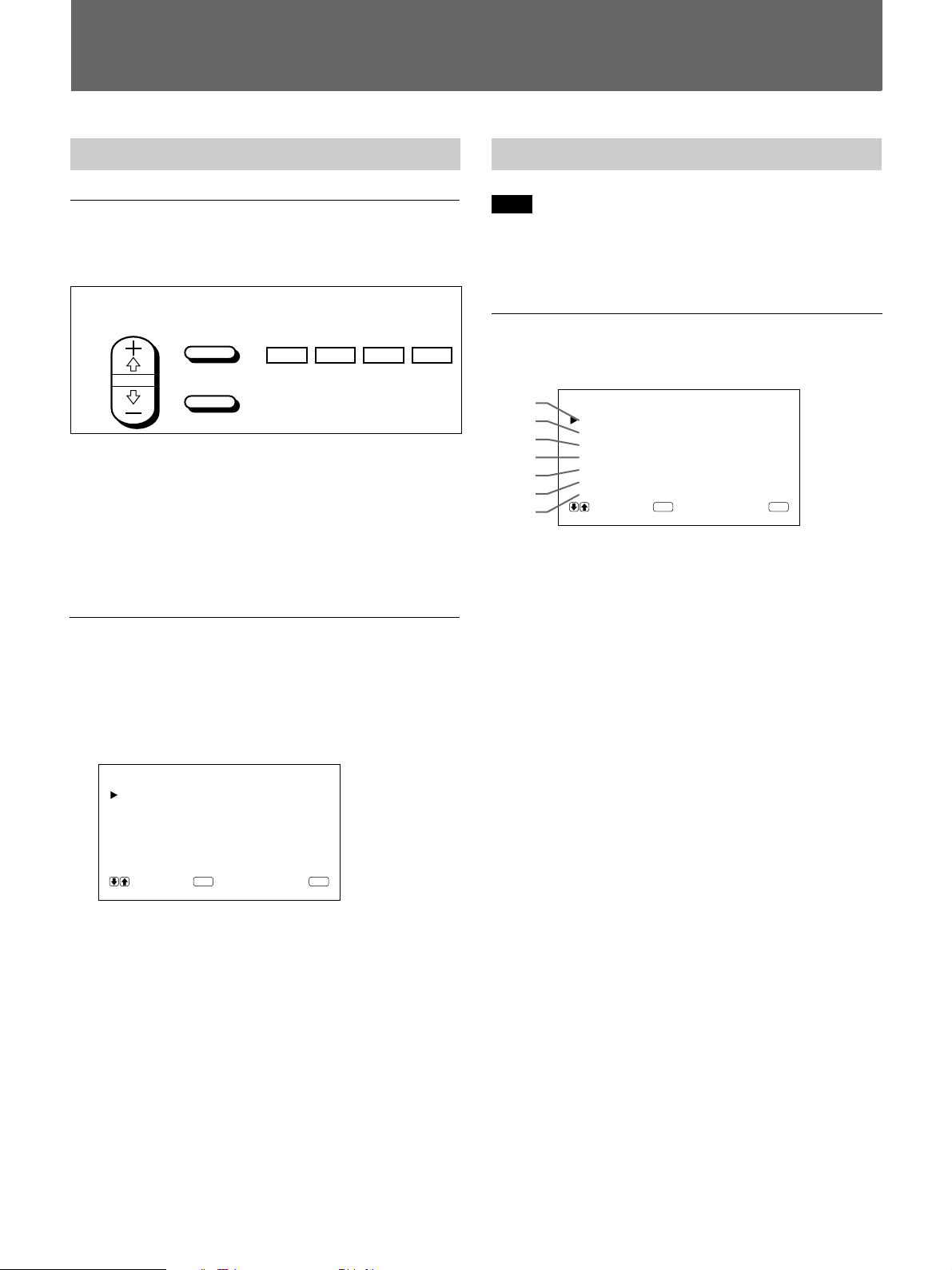
Operating Through Menus
Menu operating buttons
There are four buttons on the monitor and the Remote
Commander for menu operations.
Remote Commander Monitor
SELECT
The buttons on the control panel are used for
explanation purpose in this operating instructions.
The ENTER button on the Remote Commander has the
same function as the ENT button on the control panel
and the SELECT +>/–. buttons on the Remote
Commander as same as the >/. buttons on the control
panel.
MENU
ENTER
MENU ENT
.
>
Menu Guide
Note
“– – – –” appears next to an item when its function is
not available. The availability depends on the types of
input signal.
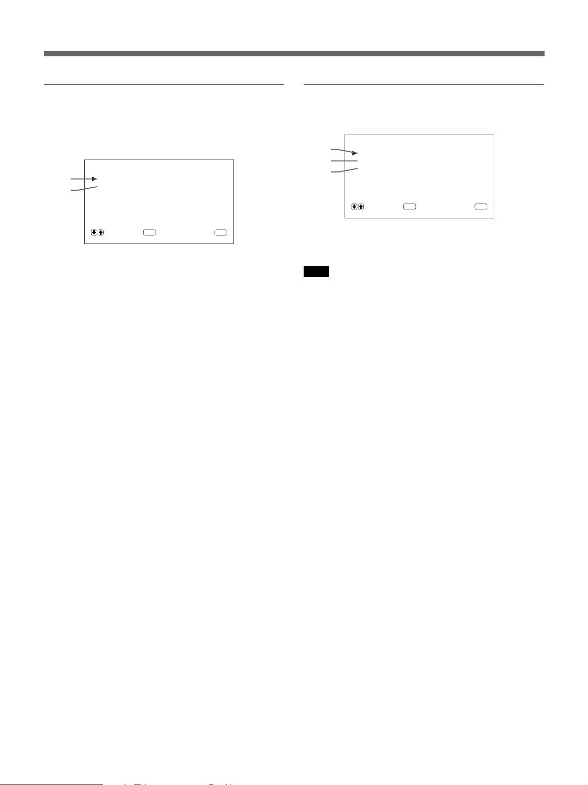
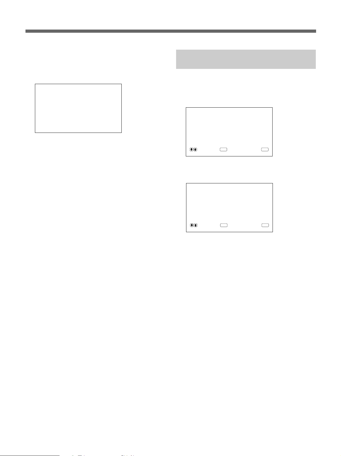
PIC CONTROL menu
This menu is used for adjusting the picture.
1
2
3
4
5
6
7
1 CONTRAST
Press > to increase the contrast and press . to
decrease it.
P IC CONTROL
CONTRAST : 80
BRIGHTNESS : 00
CHROMA : 0 0
PHASE : 00
COLOR TEMP :H I GH
PICTURE AGC : ON
RESET
SELECT CANCEL
ENTER
MENU
Configuration of the menu
To select the language used in the menu, see page
31(EN).
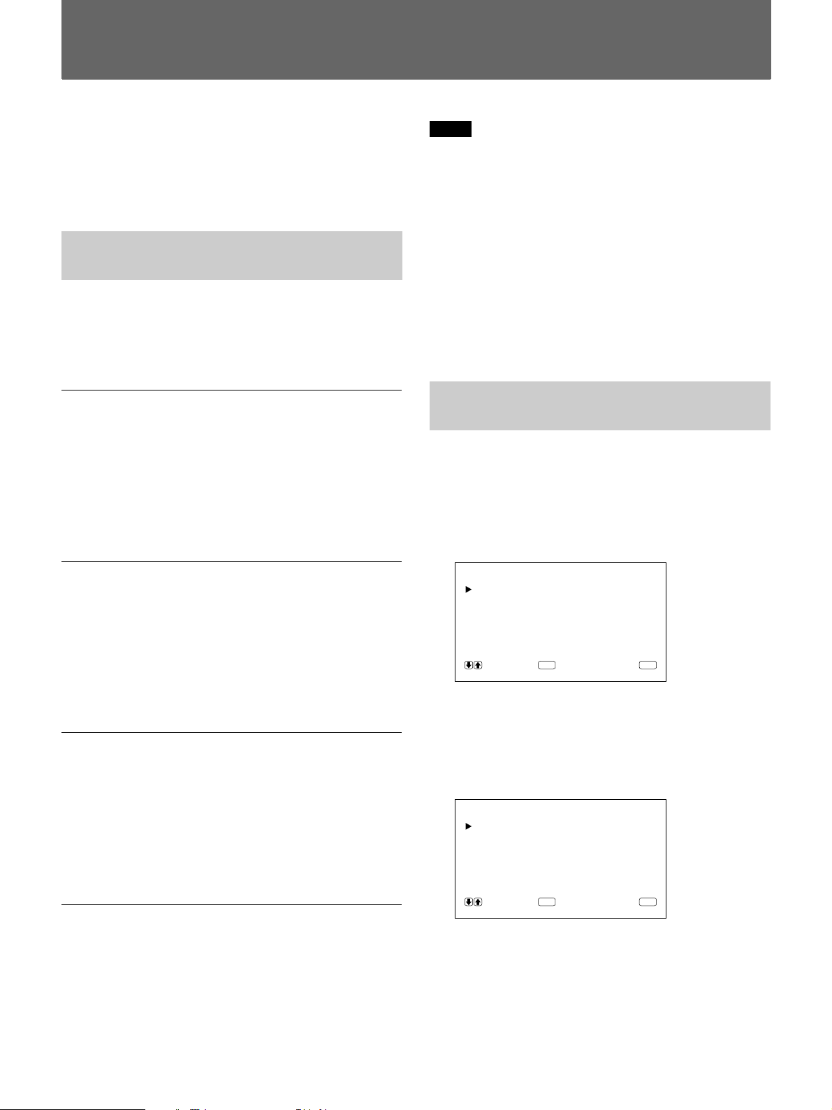
1 Press MENU.
The main menu appears on the monitor screen.
MA IN MENU
PIC CONTROL
PIC SIZE
CONF I G
MEMORY
REMOTE
STATUS
SELECT CANCEL
ENTER
MENU
2 Press >/. to move the cursor (z) and press ENT
to select a menu.
The selected menu appears on the monitor screen.
3 Press >/. to move the cursor (z) and press ENT
to select an item.
The menu for the selected item appears on the
monitor screen.
4 Press >/. to adjust or select the setting and press
ENT to set.
The setting is registered and the menu returns to
the previous menu.
To return to the normal screen, press the MENU button
repeatedly until the menu disappears.
2 BRIGHTNESS
Press > to make the picture brighter and press . to
make it darker.
3 CHROMA
Press > to increase color saturation and press . to
decrease it.
4 PHASE
Press > to make overall picture greenish and press .
to make it purplish.
5 COLOR TEMP
Select the color temperature from HIGH or LOW.
6 PICTURE AGC
Select ON to improve the contrast automatically when
a low intensity signal is input.
For details on the picture AGC function, see “Emphasizing
the Contrast of the Picture (Picture AGC Function)” on
page 24(EN).
7 RESET
Select to restore the factory settings in the PIC
CONTROL menu items 1 to 6.
For details on using the reset function, see “Restoring the
PIC CONTROL Menu Items to Original Settings” on page
25(EN).
1818 (EN)
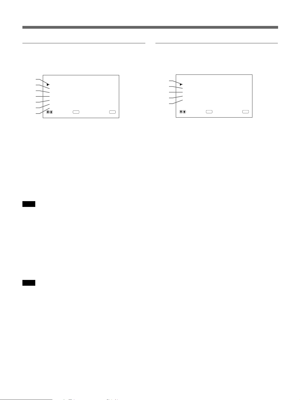
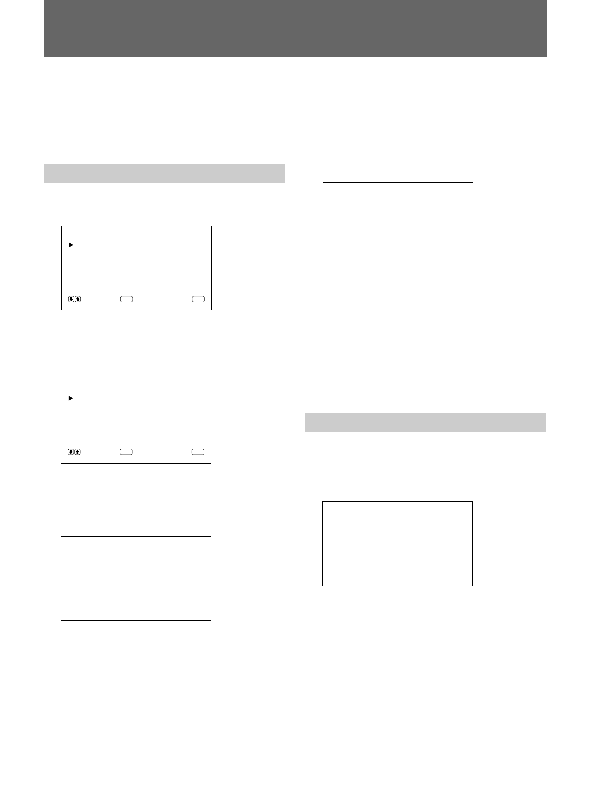
PIC SIZE menu
CONFIG menu
This menu is used for zooming, positioning, and
resizing the picture.
8
9
0
!¡
!™
!£
!¢
PIC SIZE
HSIZE : 00
HSHIFT : 00
VSIZE : 00
VSHIFT : 00
ZOOM : x1
ASPECT : 4x3
RESET
SELECT CANCEL
ENTER
MENU
8 H SIZE
Adjusts the horizontal picture size. Press > to enlarge
the horizontal size and press . to diminish it.
9 H SHIFT
Adjusts the horizontal centering. Press > to move the
picture to the right and press . to move it to the left.
0 V SIZE
Adjusts the vertical picture size. Press > to enlarge the
vertical size and press . to diminish it.
Note
Enlarging the image while the monitor is receiving
HDTV signals may cause the monitor to go into the
Offset Sampling Mode resulting in a blurred image.
!¡ V SHIFT
Adjusts the vertical centering. Press > to move the
picture up and press . to move it down.
!™ ZOOM
Zooms up the picture two, three, and four times.
This menu is used for adjusting the signal or selecting
the language.
!∞
!§
!¶
!•
!ª
CONF I G
ENHANCE : H I GH
H FI LTER : AUTO
DISPLAY : ON
POWER SAVE : 5m
LANGUAGE
SELECT CANCEL
ENTER
MENU
!∞ ENHANCE (Sharpness)
You can change the outline correction level:
LOW: Default setting for VIDEO signal
HIGH: Default setting for computer signal
!§ H FILTER
Select AUTO normally.
Select HIGH when the ringing appears on the screen.
Select LOW when the moiré pattern or noise appears
on the screen. The moiré pattern or noise decreases
even the screen looks a little blurred.
!¶ DISPLAY
Select ON to display the input signal information for
about five seconds on the top of the monitor screen
when turning on the power or switching the input
signal.
!• POWER SAVE
Set the time period to activate the power saving mode.
For details on the power saving function, see “Turning Off
the Power Automatically When There Is No Input Signal
(Power Saving Function)” on page 30(EN).
Note
Enlarging the image while the monitor is receiving
HDTV signals may cause the monitor to go into the
Offset Sampling Mode resulting in a blurred image.
!£ ASPECT
Set the aspect ratio of the picture to 4:3 or 16:9.
!¢ RESET
Select to restore the factory settings in the PIC SIZE
menu items 8 to !£.
For details on using the reset function, see “Restoring the
Original Picture Size and Position” on page 27(EN).
!ª LANGUAGE
Select the on-screen language among five languages.
Available languages are: English, German, French,
Italian and Spanish.
For details on selecting the language, see “Selecting the
On-screen Language” on page 31(EN).
19 (EN)
Using On-screen Menus
c
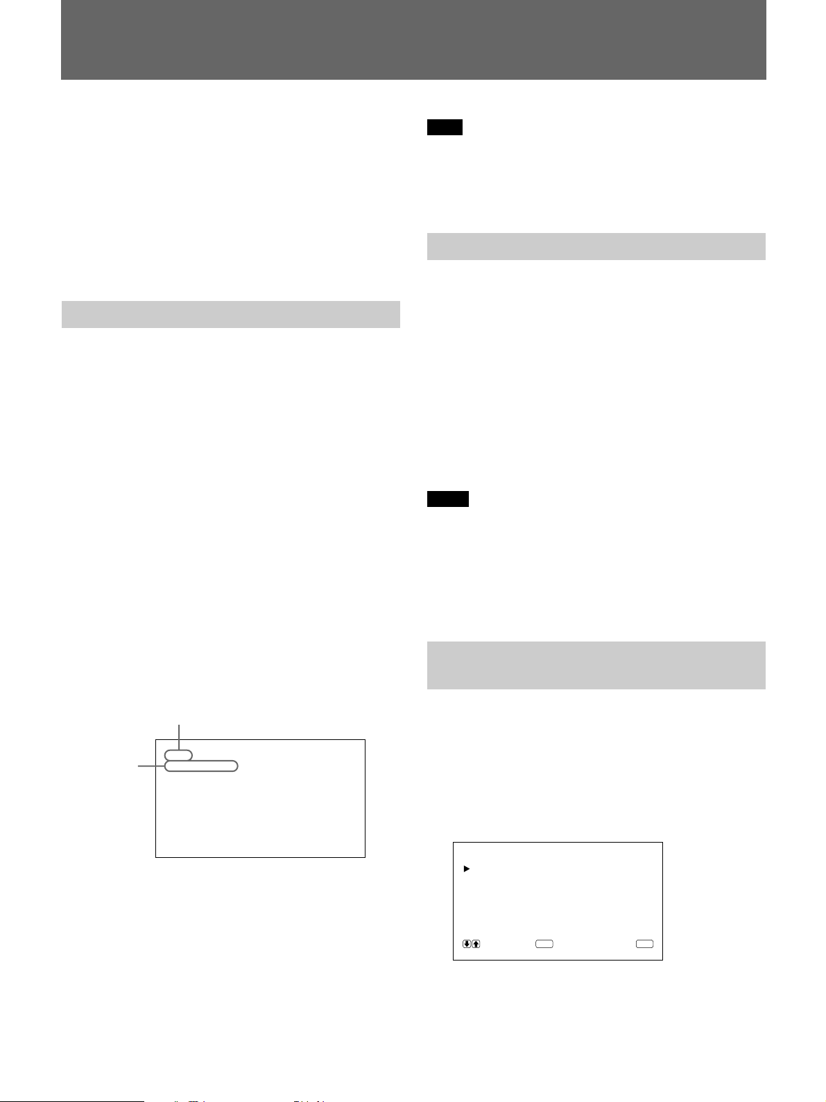
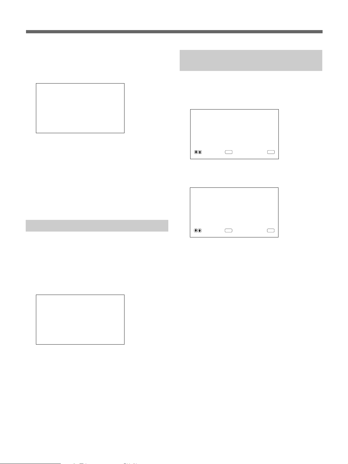
MEMORY menu
This menu is used for saving or recalling the settings
in the PIC CONTROL, PIC SIZE and CONFIG (only
for ENHANCE and H FILTER) menus.
MEMORY
@º
@¡
For details, see “Using the Memory” on page 28(EN).
@º LOAD
Recalls the preset settings.
@¡ SAVE
Saves the settings.
LOAD
SAVE
SELECT CANCEL
ENTER
MENU
REMOTE menu
This menu is used for the remote control setting.
@™
@£
@¢
@™ INDEX NO.
Sets the index number of the monitor.
Note
When you set the number, use the buttons on the
monitor.
For details on the index number, see “Operating a Specific
Monitor With the Remote Commander” on page 32(EN).
@£ REMOTE MODE
Select the Remote Commander mode.
TV: Sony monitors’ or TVs’ commander
PJ: Sony projectors’ commander
OFF: Disables the remote control.
For details, see “Using the Other Remote Commander” on
page 33(EN).
REMOTE
INDEX NO. : 001
REMOT E MODE : TV
REMOTE ONLY : OFF
SELECT CANCEL
ENTER
MENU
@¢ REMOTE ONLY
Select ON to disable the front control buttons on the
monitor. The monitor can only be controlled with the
Remote Commander. While REMOTE ONLY is ON,
the indicators on the front panel go off.
To cancel the REMOTE ONLY mode, set REMOTE
ONLY to OFF with the Remote Commander, or press
the CTRL button while pressing the u switch. The
monitor turns to the standby mode and the REMOTE
ONLY mode is canceled.
The setting in this item is still retained when the AC
power cord is disconnected.
2020 (EN)
STATUS menu
This menu is used for displaying the internal condition
of the monitor.
@∞
@§
@¶
@•
@ª
#º
@∞ Model name
Indicates the model name.
STATUS
[ PFM-500A2WU ]
SERIAL No. :2000001
OPERATION :000000H
SOFTWARE :
TEMPERATURE : OK
FAN : OK
Ver
1.00
#º FAN
The cooling fans are built in this monitor. This item
indicates whether the cooling fans work properly.
OK: Usual
NG: Unusual
When the cooling fans are unusual, NG is displayed
and the item flashes in red. The u indicator on the
control panel also flashes.
Note
When the “FAN NG” message appears, contact your
authorized Sony dealer.
When the u indicator flashes or NG indicates, see “Selfdiagnosis Function” on page 31(EN).
@§ SERIAL No.
Indicates the serial number.
@¶ OPERATION
Indicates the total operation hours.
Note
The standby mode is not counted as OPERATION
time.
@• SOFTWARE
Indicates the system software version.
@ª TEMPERATURE
Indicates whether the internal temperature of the
monitor is usual.
OK: Usual
NG: Unusual
When the internal temperature is unusual, NG is
displayed and the item flashes in red. The u indicator
on the control panel also flashes.
Note
The “TEMPERATURE NG” message may appear
when the ventilation holes are blocked or the monitor
is installed in a poorly ventilated area. In this case,
check that the ventilation holes are not blocked and
install the monitor in a good ventilated area. If the
message still displayed, contact your authorized Sony
dealer.
When the u indicator flashes or NG indicates, see “Selfdiagnosis Function” on page 31(EN).
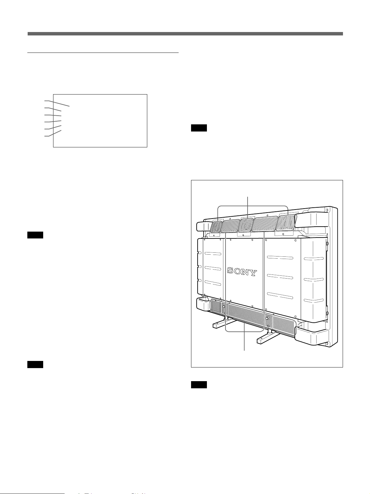
Cooling fans
Ventilation holes
Note
The upper cooling fans detect the monitor’s internal
temperature and control the fans rotations. If the
ambient temperature is high, the number of fan
rotations increase and the noise will be louder.
21 (EN)
Watching the Picture
Before you start
•Turn on the monitor.
•Turn on the connected equipment and play a video
source.
•To display the input signal information on the screen
when turning on the power or switching the input
signal, set “DISPLAY” in the CONFIG menu to ON.
•To select the on-screen language used in the menu,
see page 31(EN).
Switching the Picture
1 Press CTRL on the control panel of the monitor.
RGB1, YUV, RGB2, LINE, and Y/C buttons light
up.
2 Select the input source to be displayed by pressing
the following buttons.
RGB1:Selects the audio and video signal input
from the RGB1 connectors when the input
signal is RGB signal.
YUV: Selects the audio and video signal input
from the RGB1 connectors when the input
signal is component signal.
RGB2:Selects the audio and video signal input
from the RGB2 connectors.
LINE: Selects the audio and video signal input
from the VIDEO IN connector and
AUDIO IN jack in the LINE connectors.
Y/C: Selects the audio and video signal input
from the Y/C IN connector and AUDIO IN
jack in the LINE connectors.
Color system or horizontal/vertical frequency
Signal
type
PAL
LINE·Y/C
Note
We recommend the input source video equipment
equipped with the TBC (time base corrector). If you
receive the signal without the TBC, the picture may
disappear due to disturbance of the sync signal.
Watching a Still Picture
You can freeze the picture with the STILL button on
the Remote Commander. To freeze the picture, press
the STILL button when the motion picture is
displayed.
You can also freeze the picture by simply pressing the
> button on the control panel.
To resume the normal screen
•Press the STILL button on the Remote Commander
or > button on the control panel again.
•Switch the input signal.
Notes
•When operating the menu, the > button functions as
for the menu operation.
•The >/. buttons flash while in the still mode.
•When you set DISPLAY to ON in the CONFIG
menu, the “STILL” display appears on the top of the
monitor. To clear the display, set DISPLAY to OFF.
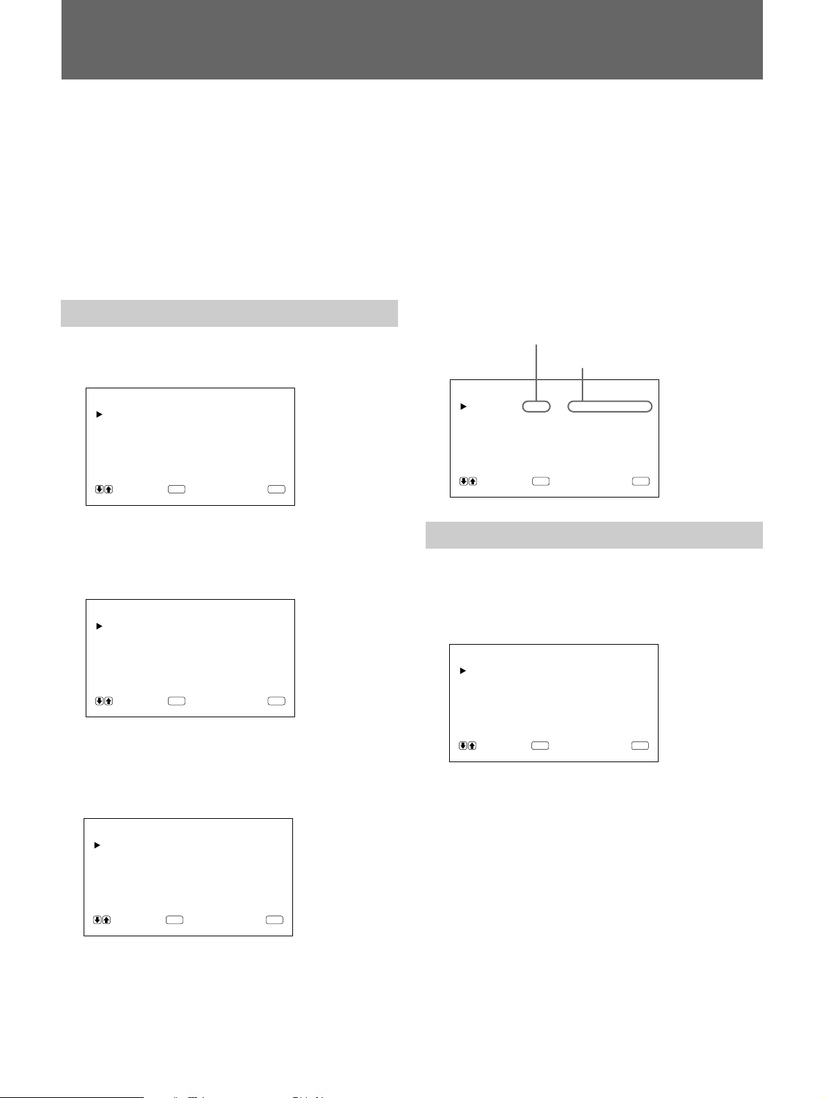
Input Signal and Monitor Status
Information Display
Input signal and monitor status information is
displayed on-screen for about five seconds when
turning on the power or switching the input signal.
To disable this function, follow the steps below.
The selected input signal appears on the monitor
screen.
You can also switch the input signal from the
Remote Commander.
2222 (EN)
1 Press MENU.
The main menu appears on the monitor screen.
MA IN MENU
PIC CONTROL
PIC SIZE
CONF I G
MEMORY
REMOTE
STATUS
SELECT CANCEL
ENTER
MENU
2 Press >/. to move the cursor (z) to “CONFIG”
and press ENT.
The CONFIG menu appears on the monitor screen.
CONF I G
ENHANCE : H I GH
H FI LTER : AUTO
DISPLAY : ON
POWER SAVE : 5m
LANGUAGE
SELECT CANCEL
ENTER
MENU
3 Press >/. to move the cursor (z) to “DISPLAY”
and press ENT.
The following menu appears on the monitor
screen.
DISPLAY : ON
Input signal Color system or horizontal/vertical
frequency display
NTSC NTSC
PAL PAL
VGAa) (Graphics) 31.5 kHz 60 Hz
VGA (Text) 31.5 kHz 70 Hz
HDTV 33.8 kHz 60 Hz
Macb) 13" 35.0 kHz 67 Hz
VESAc) 800×600 37.9 kHz 60 Hz
VESA 1024×768 48.4 kHz 60 Hz
Mac 16" 49.7 kHz 75 Hz
ATId) 1280×1024 64.0 kHz 60 Hz
Mac 21" 68.7 kHz 75 Hz
VESA 1280×1024 80.0 kHz 75 Hz
a) VGA is a registered trademark of the International
Business Machines Corporation, USA.
b) Mac (Macintosh) is a registered trademark of Apple
Computer, Inc.
c) VESA is a registered trademark of Video Electronics
Standard Association.
d) ATI is a registered trademark of ATI Technologies, Inc.
4 Press > to set “DISPLAY” to OFF and press ENT.
The DISPLAY function is disabled.
To activate the information function, set “DISPLAY”
to ON at the step 4 above.
Note
You can display the input signal information anytime
by pressing the DISPLAY button on the Remote
Commander, regardless of the above setting.
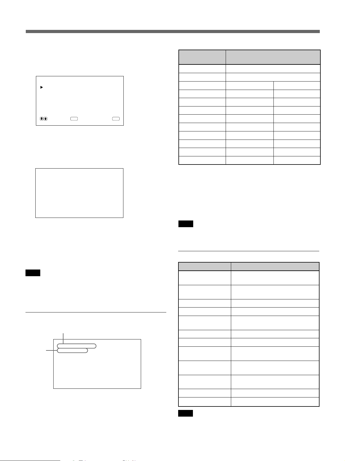
The input signal information list
Color system or horizontal/vertical frequency
31.5
kHz
/60
Signal
type
RGB1 ·RGB
Hz
Note
When inputting the HDTV signal, input the tri-level
sync signal to the G/Y IN connector.
Actual on-screen display of the monitor status
On-screen display Significance
31.5kHz / 60Hz (eg.) The selected input signal is
computer RGB.
525 / 60 (eg.) The selected input signal is RGB or
component video.
NTSC The selected input signal is NTSC.
PAL The selected input signal is PAL.
OTHERS The input signal is out of the capture
range.
NO SYNC There is no input signal.
MUTING The sound is muted.
RGB1 RGB The signal mode of RGB1 is set to
RGB.
RGB1 YUV The signal mode of RGB1 is set to
component video.
LINE COMP Composite video input is selected at
LINE.
LINE Y/C Y/C video input is selected at LINE.
STILL The picture is frozen.
Note
If computer signals more than 100kHz are input and if
the monitor can receive the signals, the screen display
(horizontal frequency) will be fixed at 99.9kHz.
23 (EN)
Adjusting the Picture
While watching the picture, you can adjust contrast,
brightness, chroma, and phase to suit your taste. The
adjustments can be carried out for each input signal
separately. You can also store the adjusted levels in
memory.
Adjusting the Contrast,
Brightness, Chroma, and Phase
Press MENU so that the main menu appears on the
monitor screen and select the “CONTRAST”,
“BRIGHTNESS”, “CHROMA”, or “PHASE” from the
PIC CONTROL menu with the >/. buttons.
CONTRAST
Select the “CONTRAST” with the >/. buttons and
press the ENT button.
Adjust the contrast with the >/. buttons in the range
from MIN (0) to MAX (+100).
>: to increase picture contrast
.: to decrease picture contrast
Notes
•CHROMA and PHASE controls do not function with
RGB signal.
•PHASE control does not function with component
signal.
•PHASE control does not function with PAL color
source.
•Do not change the CHROMA/PHASE (NTSC only)
level when the selected signal is not NTSC or PAL.
Although it gives no effect to the current picture, it
does affect the picture of the NTSC or PAL signal
which is input later.
Emphasizing the Contrast of the
Picture (Picture AGC Function)
When the intensity of the picture is low, this function
works to improve the contrast automatically.
Turn on this function when the image source is dark.
1 Press MENU.
The main menu appears on the monitor screen.
BRIGHTNESS
Select the “BRIGHTNESS” with the >/. buttons and
press the ENT button.
Adjust the brightness with the >/. buttons in the
range from MIN (–50) to MAX (+50).
>: to make overall picture greenish
.: to make overall picture purplish
CHROMA
Select the “CHROMA” with the >/. buttons and
press the ENT button.
Adjust the chroma with the >/. buttons in the range
from MIN (–50) to MAX (+50).
>: to increase color intensity
.: to decrease color intensity
PHASE
Select the “PHASE” with the >/. buttons and press
the ENT button.
Adjust the phase with the >/. buttons in the range
from MIN (–50) to MAX (+50).
>: to make overall picture greenish
.: to make overall picture purplish
MA IN MENU
PIC CONTROL
PIC SIZE
CONF I G
MEMORY
REMOTE
STATUS
SELECT CANCEL
ENTER
MENU
2 Press >/. to move the cursor (z) to “PIC
CONTROL” and press ENT.
The PIC CONTROL menu appears on the monitor
screen.
PIC CONTROL
CONTRAST : 80
BRIGHTNESS : 00
CHROMA : 0 0
PHASE : 00
COLOR TEMP :H I GH
PICTURE AGC : ON
RESET
SELECT CANCEL
ENTER
MENU
2424 (EN)
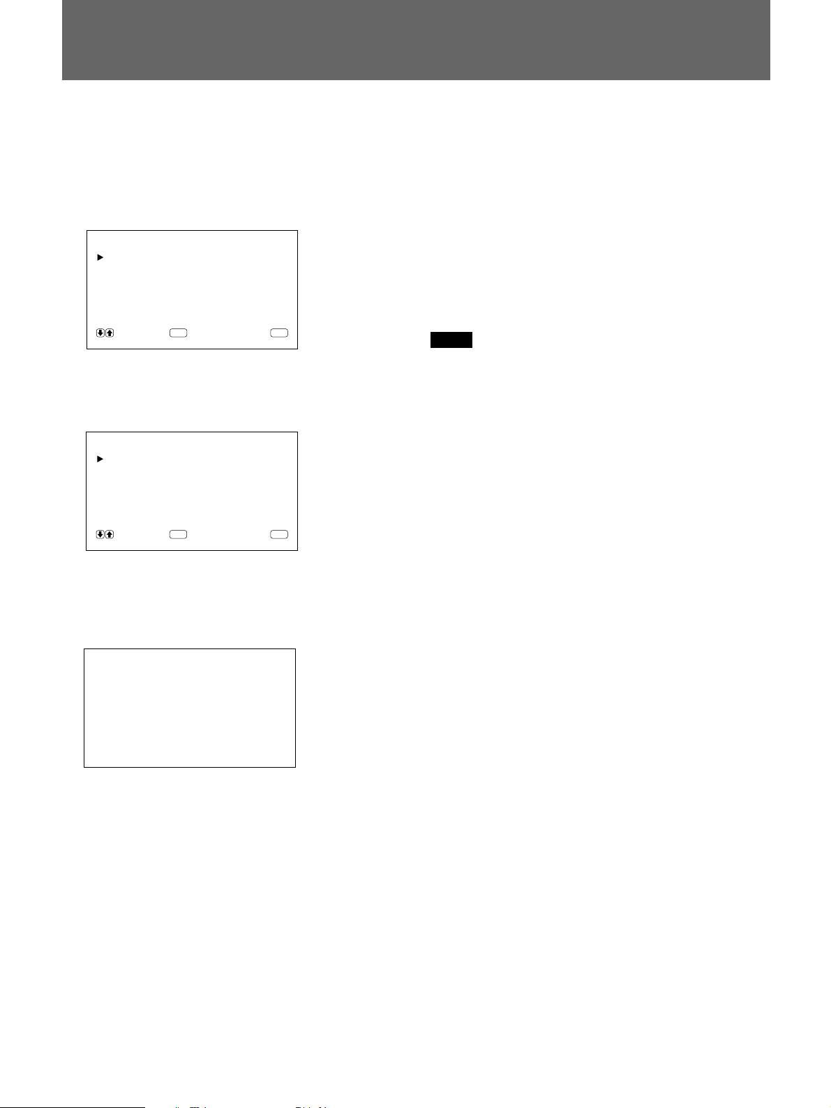
3 Press >/. to move the cursor (z) to “PICTURE
AGC” and press ENT.
The following menu appears on the monitor
screen.
PICTURE AGC : OFF
Restoring the PIC CONTROL
Menu Items to Original Settings
1 In the PIC CONTROL menu, Press >/. to move
the cursor (z) to “RESET” and press ENT.
The following menu appears on the monitor
screen.
RESET : NO
4 Press >/. to set “PICTURE AGC” to ON.
5 Press ENT.
The menu returns to the PIC CONTROL menu.
SELECT CANCEL
ENTER
MENU
2 Press >/..
“NO” changes to “YES.”
RESET : YES
SELECT CANCEL
ENTER
MENU
3 Press ENT.
The PIC CONTROL menu items are restored.
To cancel the reset function, press the MENU button
before pressing the ENT button.
25 (EN)
Zooming, Resizing, and Positioning the Picture
You can shift the position of the picture so that it fits in
the screen, or adjust the vertical and horizontal size of
the picture separately.
You can zoom up the picture making it two, three, or
four times as large as the original size.
Resizing the Picture
1 Press MENU.
The main menu appears on the monitor screen.
MA IN MENU
PIC CONTROL
PIC SIZE
CONF I G
MEMORY
REMOTE
STATUS
SELECT CANCEL
ENTER
MENU
2 Press >/. to move the cursor (z) to “PIC SIZE”
and press ENT.
The PIC SIZE menu appears on the monitor
screen.
PIC SIZE
HSIZE : 00
HSHIFT : 00
VSIZE : 00
VSHIFT : 00
ZOOM : x1
ASPECT : 4x3
RESET
SELECT CANCEL
ENTER
MENU
3 Press >/. to move the cursor (z) to “H SIZE” and
press ENT.
The following menu appears on the monitor
screen.
5 Press ENT.
The menu returns to the PIC SIZE menu.
6 Press >/. to move the cursor (z) to “V SIZE”
and press ENT.
The following menu appears on the monitor
screen.
VSIZE : 00
7 Press >/. to resize the picture.
>: to expand vertical size
.: to reduce vertical size
The vertical picture size is indicated on the
monitor screen from MIN(–50) to MAX(+50). The
factory value is 00.
8 Press ENT.
The menu returns to the PIC SIZE menu.
Adjusting the Picture Position
1 In the PIC SIZE menu, press >/. to move the
cursor (z) to “H SHIFT” and press ENT.
The following menu appears on the monitor
screen.
HSHIFT : 00
HSIZE : 00
4 Press >/. to resize the picture.
>: to expand horizontal size
.: to reduce horizontal size
The horizontal picture size is indicated on the
monitor screen in the range from MIN(–50) to
MAX(+50). The factory value is 00.
2626 (EN)
2 Press >/. to shift the picture.
>: to shift the picture to the right
.: to shift the picture to the left
The horizontal picture position is indicated on the
monitor screen from MIN(–50) to MAX(+50). The
factory value is 00.
3 Press ENT.
The menu returns to the PIC SIZE menu.
4 Press >/. to move the cursor (z) to “V SHIFT”
and press ENT.
The following menu appears on the monitor
screen.
VSHIFT : 00
Restoring the Original Picture
Size and Position
1 In the PIC SIZE menu, press >/. to move the
cursor (z) to “RESET” and press ENT.
The following menu appears on the monitor
screen.
RESET : NO
5 Press >/. to shift the picture.
>: to shift the picture upward
.: to shift the picture downward
The vertical picture position is indicated on the
monitor screen from MIN(–50) to MAX(+50). The
factory value is 00.
6 Press ENT.
The menu returns to the PIC SIZE menu.
Zooming Up the Picture
You can also operate with the ZOOM button on the
Remote Commander.
1 In the PIC SIZE menu, press >/. to move the
cursor (z) to “ZOOM” and press ENT.
The following menu appears on the monitor
screen.
ZOOM : x1
SELECT CANCEL
ENTER
MENU
2 Press >/..
“NO” changes to “YES.”
RESET : YES
SELECT CANCEL
ENTER
MENU
3 Press ENT.
The original picture size and position are restored.
To cancel the reset function, press the MENU button
before pressing the ENT button.
2 Press >/. to set zoom.
Each time you press >, the picture is magnified by
two, three, and four times respectively.
To zoom down, press ..
3 Press ENT.
The menu returns to the PIC SIZE menu.
27 (EN)
Using the Memory
You can save the current picture condition by each
input signal using MEMORY function.
The saved condition can be restored whenever
necessary.
The items in PIC CONTROL, PIC SIZE and CONFIG
(only for ENHANCE and H FILTER) menus can be
memorized.
You can save the picture condition of up to five input
signals.
Storing the Current Condition
1 Press MENU.
The main menu appears on the monitor screen.
MA IN MENU
PIC CONTROL
PIC SIZE
CONF I G
MEMORY
REMOTE
STATUS
SELECT CANCEL
ENTER
MENU
4 Press >/. to move the cursor (z) to MEM 1 to 5
and press ENT.
“COMPLETED” message appears for about five
seconds.
The current data is stored under the selected
memory number.
If any data has been stored in the selected memory
number, the signal type and the color system or
horizontal frequency/vertical frequency are now
displayed on the right column next to the selected
memory number.
Signal type
Color system or horizontal/vertical frequency
SAVE
MEM 1 : RGB 31 . 5
MEM 2 : EMPTY
MEM 3 : EMPTY
MEM 4 : EMPTY
MEM 5 : EMPTY
SELECT CANCEL
ENTER
kHz60Hz
MENU
2 Press >/. to move the cursor (z) to “MEMORY”
and press ENT.
The MEMORY menu appears on the monitor
screen.
MEMORY
LOAD
SAVE
SELECT CANCEL
ENTER
MENU
3 Press >/. to move the cursor (z) to “SAVE” and
press ENT.
The following menu appears on the monitor
screen.
SAVE
MEM 1 : EMPTY
MEM 2 : EMPTY
MEM 3 : EMPTY
MEM 4 : EMPTY
MEM 5 : EMPTY
SELECT CANCEL
ENTER
MENU
Calling Up the Stored Condition
1 In the MEMORY menu, press >/. to move the
cursor (z) to “LOAD” and press ENT.
The following menu appears on the monitor
screen.
LOAD
MEM 1:RGB 31.5
MEM 2 : EMPTY
MEM 3 : EMPTY
MEM 4 : EMPTY
MEM 5 : EMPTY
SELECT CANCEL
ENTER
kHz60Hz
MENU
2 Press >/. to move the cursor (z) to MEM 1 to 5
and press ENT.
“COMPLETED” message appears for about five
seconds.
The picture is adjusted to the selected condition.
2828 (EN)

Notes
•You cannot recall the memory data if the selected
signal is different from the preset signal.
•The following items can be memorized:
PIC CONTROL menu
– CONTRAST
– BRIGHTNESS
– CHROMA
– PHASE
– COLOR TEMP
– PICTURE AGC
PIC SIZE menu
– H SIZE
– H SHIFT
– V SIZE
– V SHIFT
– ZOOM
– ASPECT
CONFIG menu
– ENHANCE
– H FILTER
29 (EN)
Turning Off the Power Automatically When There Is
No Input Signal (Power Saving Function)
This unit automatically turns off the power after
certain period if there is no input signal from the
RGB1 or RGB2 connectors. (Power saving function)
1 Press MENU.
The main menu appears on the monitor screen.
MA IN MENU
PIC CONTROL
PIC SIZE
CONF I G
MEMORY
REMOTE
STATUS
SELECT CANCEL
ENTER
MENU
2 Press >/. to move the cursor (z) to “CONFIG”
and press ENT.
The CONFIG menu appears on the monitor screen.
CONF I G
ENHANCE : H I GH
H FI LTER :AUTO
DISPLAY : ON
POWER SAVE : 5m
LANGUAGE
SELECT CANCEL
ENTER
MENU
3 Press >/. to move the cursor (z) to “POWER
SAVE” and press ENT.
The following menu appears on the monitor
screen.
To cancel the power saving function
•Input the sync signal again.
•Press the u switch on the control panel or the
POWER switch on the Remote Commander.
Signal specification for using the power
saving function
RGB1: When the sync signal is connected to the HD/
COMP IN connector.
RGB2: When the sync signal is connected to the
13th pin of the RGB IN (D-sub 15-pin) connector.
Notes
•The power saving function does not work when the
signal is input from the LINE connectors.
•If the sync signal is not connected to the HD/COMP
IN connector, the unit does not turn on even if the
sync signal is input. Be sure to set POWER SAVE to
OFF when only the RGB signal or component signal
is connected.
•If the sync signal is not connected to the 13th pin of
the RGB IN (D-sub 15-pin) connector, the unit does
not turn on even if the sync signal is input. Be sure to
set POWER SAVE to OFF when only the RGB
signal is connected.
POWER SAVE : 5m
4 Press >/. to select the period to turn into the
power saving mode.
OFF: The power saving function does not work.
5 m: Turn into the power saving mode after five
minutes if there is no input signal.
10 m: Turn into the power saving mode after 10
minutes if there is no input signal.
The power indicator flashes when the unit is in the
power saving mode.
3030 (EN)
 Loading...