

Sony RM-971, SS-SP20B, BKM-V11, BKM-V10, PFM-42V1P Service Manual
...
FLAT PANEL DISPLAY
PFM-42V1
PFM-42V1A
PFM-42V1E
PFM-42V1P
VIDEO INPUT ADAPTOR
BKM-V10
COMPONENT/RGB INPUT ADAPTOR
BKM-V11
SPEAKER SYSTEM
SS-SP20B
REMOTE COMMANDER
RM-971
SERVICE MANUAL
1st Edition (Revised 1)
! WARNING
This manual is intended for qualified service personnel only.
To reduce the risk of electric shock, fire or injury, do not perform any servicing other than that
contained in the operating instructions unless you are qualified to do so. Refer all servicing to
qualified service personnel.
! WARNUNG
Die Anleitung ist nur für qualifiziertes Fachpersonal bestimmt.
Alle Wartungsarbeiten dürfen nur von qualifiziertem Fachpersonal ausgeführt werden. Um die
Gefahr eines elektrischen Schlages, Feuergefahr und Verletzungen zu vermeiden, sind bei
Wartungsarbeiten strikt die Angaben in der Anleitung zu befolgen. Andere als die angegeben
Wartungsarbeiten dürfen nur von Personen ausgeführt werden, die eine spezielle Befähigung
dazu besitzen.
! AVERTISSEMENT
Ce manual est destiné uniquement aux personnes compétentes en charge de l’entretien. Afin
de réduire les risques de décharge électrique, d’incendie ou de blessure n’effectuer que les
réparations indiquées dans le mode d’emploi à moins d’être qualifié pour en effectuer d’autres.
Pour toute réparation faire appel à une personne compétente uniquement.
WARNING!!
AN INSULATED TRANSFORMER SHOULD BE USED DURING
ANY SERVICE TO AVOID POSSIBLE SHOCK HAZARD, BECAUSE OF LIVE CHASSIS.
THE CHASSIS OF THIS RECEIVER IS DIRECTLY CONNECTED
TO THE AC POWER LINE.
SAFETY-RELATED COMPONENT WARNING !!
COMPONENTS IDENTIFIED BY A
DIAGRAMS, EXPLODED VIEWS AND IN THE PARTS LIST ARE
CRITICAL TO SAFE OPERATION. REPLACE THESE COMPONENTS WITH SONY PAR TS WHOSE P ART NUMBERS APPEAR
AS SHOWN IN THIS MANUAL OR IN SUPPLEMENTS PUBLISHED BY SONY . CIRCUIT ADJUSTMENTS THA T ARE CRITICAL TO SAFE OPERATION ARE IDENTIFIED IN THIS MANU AL.
FOLLOW THESE PROCEDURES WHENEVER CRITICAL COMPONENTS ARE REPLACED OR IMPROPER OPERATION IS
SUSPECTED.
!!
! MARK ON THE SCHEMA TIC
!!
ATTENTION!!
AFIN D’ÉVITER TOUT RISQUE D’ÉLECTROCUTION
PROVENANT D’UN CHÂSSIS SOUS TENSION, UN
TRANSFORMA TEUR D’ISOLEMENT DOIT ETRE UTILISÉ LORS
DE TOUT DÉPANNA GE.
LE CHÂSSIS DE CE RÉCEPTEUR EST DIRECTEMENT
RACCORDÉ Á L’ALIMENTATION SECTEUR.
ATTENTION AUX COMPOSANTS RELATIFS Á LA
SÉCURITÉ!!
LES COMPOSANTS IDENTIFIÉS PAR UNE MAPQUE
LES SCHÉMAS DE PRINCIPE, LES VUES EXPLOSÉES ET LES
LISTES DE PIECES SONT D’UNE IMPORTANCE CRITIQUE
POUR LA SÉCURITÉ DU FONCTIONNEMENT. NE LES
REMPLACER QUE PAR DES COMPOSANTS SONY DONT LE
NUMÉRO DE PIÈCE EST INDIQUÉ DANS LE PRÉSENT MANUEL
OU DANS DES SUPPLÉMENTS PUBLIÉS PAR SONY. LES
RÉGLAGES DE CIRCUIT DONT L’IMPORT ANCE EST CRITIQUE
POUR LA SÉCURITÉ DU FONCTIONNEMENT SONT
IDENTIFIÉS DANS LE PRÉSENT MANUEL. SUIVRE CES
PROCÉDURES LORS DE CHAQUE REMPLACEMENT DE
COMPOSANTS CRITIQUES, OU LORSQU’UN MAUVAIS
FONCTIONNEMENT EST SUSPECTÉ.
PFM-42V1/42V1A/42V1E/42V1P
!!
! SUR
!!

CAUTION
ADVARSEL
Danger of explosion if battery is incorrectly replaced.
Replace only with the same or equivalent type
recommended by the manufacturer.
Dispose of used batteries according to the
manufacturer’s instructions.
Vorsicht!
Explosionsgefahr bei unsachgemäßem Austausch
der Batterie.
Ersatz nur durch denselben oder einen vom
Hersteller empfohlenen ähnlichen Typ. Entsorgung
gebrauchter Batterien nach Angaben des
Herstellers.
ATTENTION
Il y a danger d’explosion s’il y a remplacement
incorrect de la batterie.
Remplacer uniquement avec une batterie du même
type ou d’un type équivalent recommandé par le
constructeur.
Mettre au rebut les batteries usagées conformément
aux instructions du fabricant.
Lithiumbatteri - Eksplosjonsfare.
Ved utskifting benyttes kun batteri som
anbefalt av apparatfabrikanten.
Brukt batteri returneres
apparatleverandøren.
VARNING
Explosionsfara vid felaktigt batteribyte.
Använd samma batterityp eller en likvärdig typ
som rekommenderas av apparattillverkaren.
Kassera använt batteri enligt gällande
föreskrifter.
VAROITUS
Paristo voi räjähtää jos se on virheellisesti
asennettu.
Vaihda paristo ainoastaan laitevalmistajan
suosittelemaan tyyppiin.
Hävitä käytetty paristo valmistajan ohjeiden
mukaisesti.
Lithiumbatteri-Eksplosionsfare ved fejlagtig
Udskiftning må kun ske med batteri
af samme fabrikat og type.
Levér det brugte batteri tilbage til leverandøren.
PFM-42V1/42V1A/42V1E/42V1P
ADVARSEL!
håndtering.
1 (P)
For the customers in the Netherlands
Voor de klanten in Nederland
Hoe u de batterijen moet verwijderen, leest u in de tekst
van deze handleiding.
Gooi de batterij niet weg maar lever deze in als klein
chemisch afval (KCA).
Für Kunden in Deutschland
Entsorgungshinweis: Bitte werfen Sie nur entladene
Batterien in die Sammelboxen beim Handel oder den
Kommunen. Entladen sind Batterien in der Regel dann,
wenn das Gerät abschaltet und signalisiert “Batterie
leer” oder nach längerer Gebrauchsdauer der Batterien
“nicht mehr einwandfrei funktioniert”. Um
sicherzugehen, kleben Sie die Batteriepole z.B. mit
einem Klebestreifen ab oder geben Sie die Batterien
einzeln in einen Plastikbeutel.
2 (P)
PFM-42V1/42V1A/42V1E/42V1P

Table of Contents
1. Service Overview
1-1. Appearance Figure ......................................................................................1-1
1-2. Board Locations ..........................................................................................1-1
1-3. Disassembly ................................................................................................1-2
1-3-1. OP-1 Board and Blank Panel ..................................................... 1-2
1-3-2. Rear Cover Assembly ................................................................1-3
1-3-3. G (Power) Board ........................................................................1-3
1-3-4. A (Main) Board ..........................................................................1-4
1-3-5. L (Audio) Board and AC Inlet ...................................................1-5
1-3-6. I (Connection) Board.................................................................. 1-5
1-3-7. T-R/T-L (SP), TEMP, H2 (User Control) Boards..................... 1-6
1-3-8. Bezel Assembly-1 ...................................................................... 1-7
1-3-9. Bezel Assembly-2 ...................................................................... 1-8
1-3-10. Plasma Display Panel-1.............................................................. 1-9
1-3-11. Plasma Display Panel-2............................................................ 1-10
1-3-12. YDB, YDT Boards...................................................................1-11
1-3-13. Y-SUS Board ........................................................................... 1-11
1-3-14. CTRL Board.............................................................................1-12
1-3-15. XR Board ................................................................................. 1-13
1-3-16. Z-SUS Board ............................................................................ 1-13
1-4. Warning on Power Connection .................................................................1-14
2. Electrical Adjustment
2-1. Set Up Adjustment ......................................................................................2-1
2-2. Adjustment for White Balance....................................................................2-1
2-2-1. AD Calibration ...........................................................................2-1
2-2-2. White Balance Adjustment ........................................................2-2
2-2-3. 11000 K Color Adjustment ........................................................2-2
2-2-4. 9300 K Color Adjustment ..........................................................2-2
2-2-5. 6500 K Color Adjustment ..........................................................2-2
2-2-6. Adjustment for the Power Board When the Panel is Replaced..2-3
2-3. Adjustment for Panel................................................................................... 2-3
2-3-1. Application Object .....................................................................2-3
2-3-2. Notes ..........................................................................................2-3
2-3-3. Adjustment Items .......................................................................2-4
2-3-4. Adjusting the Board Group (Applying the Tools) ..................... 2-4
2-3-5. Adjustment after Assembling (PDP Module Adjustment)......... 2-5
PFM-42V1/42V1A/42V1E/42V1P
1

3. Troubleshooting Guide
3-1. Out of Order on Power ................................................................................ 3-1
3-2. No Raster State............................................................................................ 3-3
3-3. Sound Troubleshooting ...............................................................................3-6
3-4. No Raster on Analog Signal........................................................................3-7
3-5. Trouble Shooting for Panel .........................................................................3-8
3-5-1. Checking for No Picture............................................................. 3-8
3-5-2. Hitch Diagnosis Following Display Condition ........................3-10
4. Spare Parts
4-1. Notes on Repair Parts..................................................................................4-1
4-2. Exploded Views ..........................................................................................4-2
2
PFM-42V1/42V1A/42V1E/42V1P
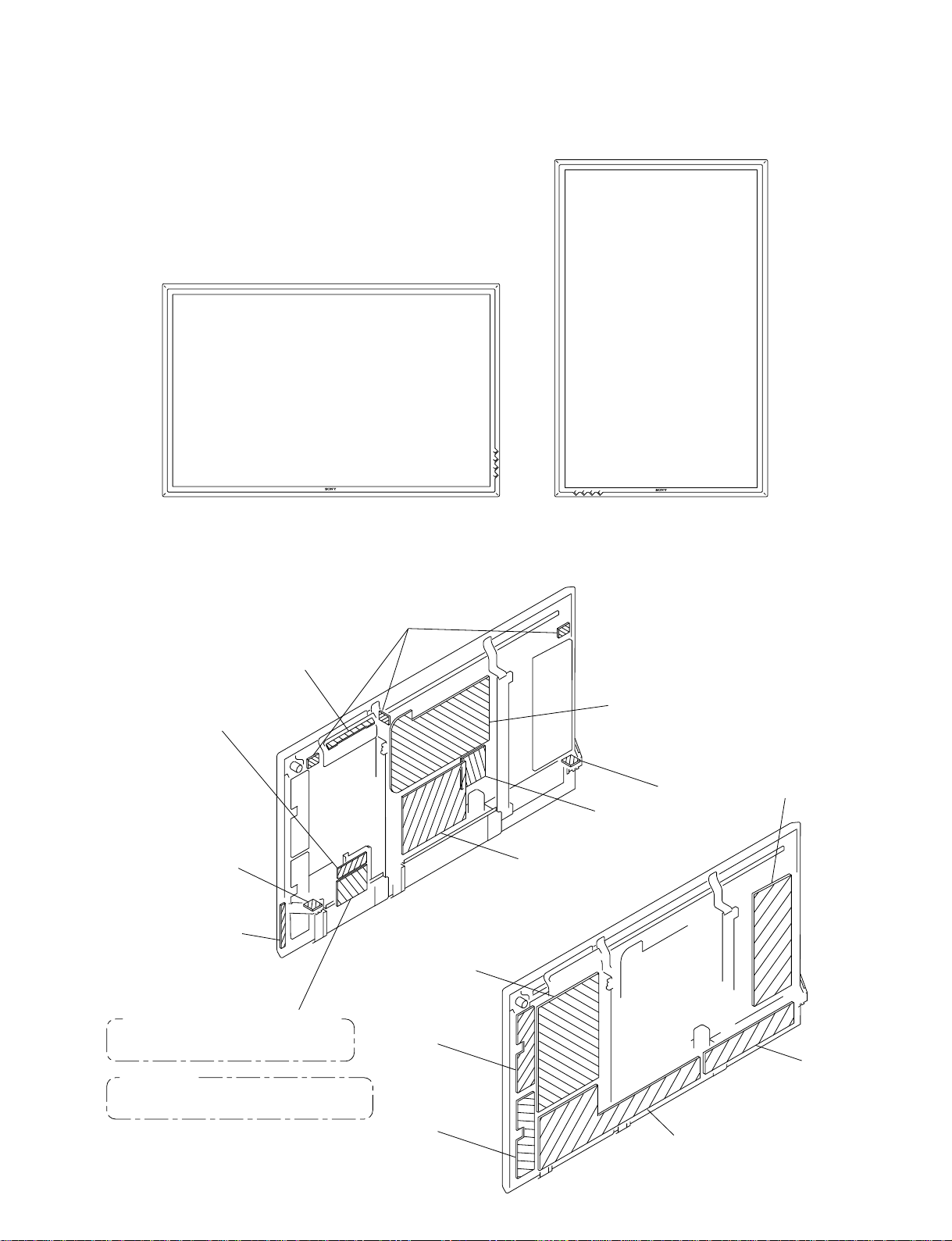
1-1. Appearance Figure
Section 1
Service Overview
PFM-42V1
PFM-42V1A
PFM-42V1E
1-2. Board Locations
H-2 (USER CONTROL)
I (CONNECTION)
T-R (SP)
H-1 (SW)
TEMP
A (MAIN)
PFM-42V1P
G (POWER)
L (AUDIO)
T-L (SP)
Z-SUS
PFM-42V1, PFM-42V1A, PFM-42V1P
OP-1 (BKM-V10)
BKM-V11 (Available Separately)
PFM-42V1E
BKM-V10 (Available Separately)
BKM-V11 (Available Separately)
PFM-42V1/42V1A/42V1E/42V1P
YDT
YDB
Y-SUS
XR
CTRL
1-1
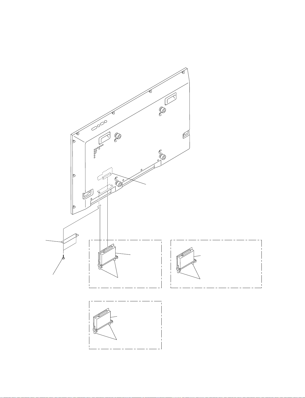
1-3. Disassembly
1-3-1. OP-1 Board and Blank Panel
CN304
I (Connection) board
Blank panel
PFM-42V1E (Only)
Two screws
PFM-42V1, PFM-42V1P,
PFM-42V1A
Loosen the two screws.
PFM-42V1, PFM-42V1P,
PFM-42V1A
BKM-V11
(Available Separately)
Loosen the two screws.
OP-1 board
(BKM-V10)
PFM-42V1E
BKM-V10 (Available Separately)
BKM-V11 (Available Separately)
Loosen the two screws.
1-2
PFM-42V1/42V1A/42V1E/42V1P
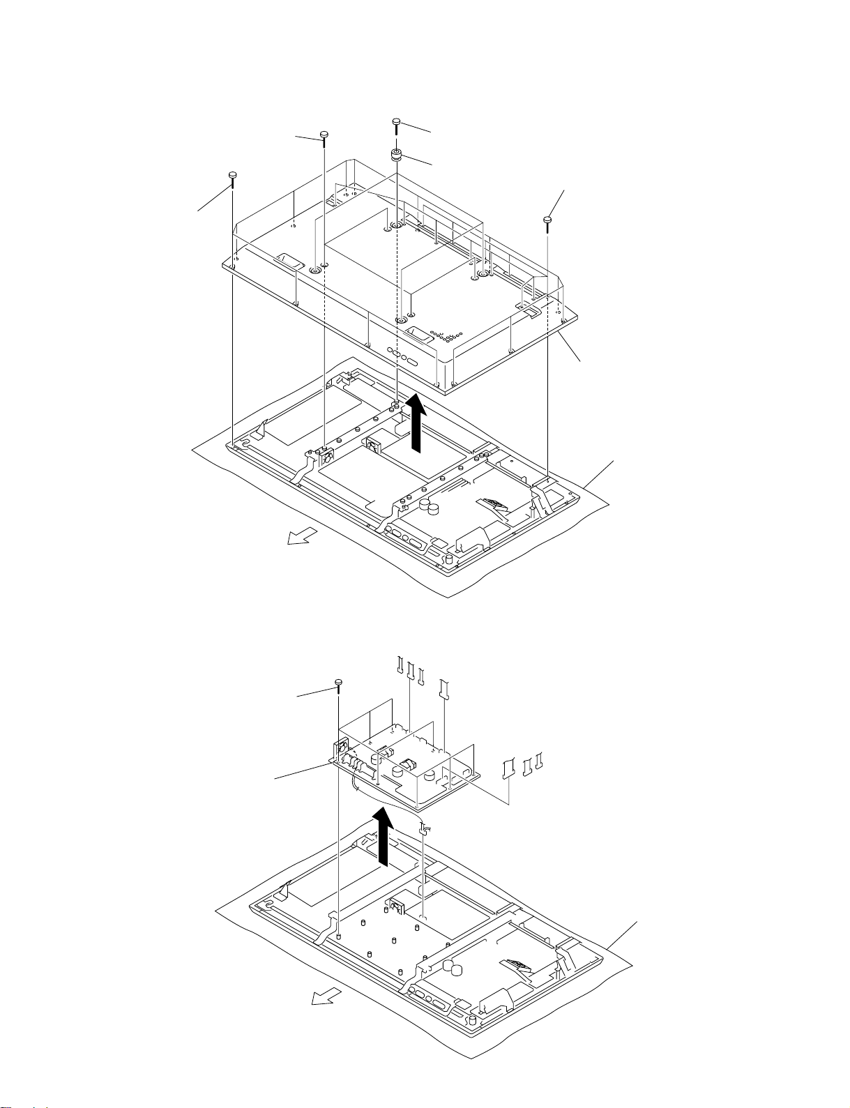
1-3-2. Rear Cover Assembly
3 Four screws
4 Fourteen screws
1 Four screws
2 Four knobs
5 Twelve screws
6 Rear cover assembly
Conductive cushion
UPPER
SIDE
1-3-3. G (Power) Board
. Remove the rear cover assembly. (Refer to 1-3-2.)
1 Eight screws
2 G (Power) board,
DC fan
CN01
CN801
CN802
CN23
CN803
CN805
CN807
CN806
Conductive cushion
PFM-42V1/42V1A/42V1E/42V1P
UPPER
SIDE
1-3
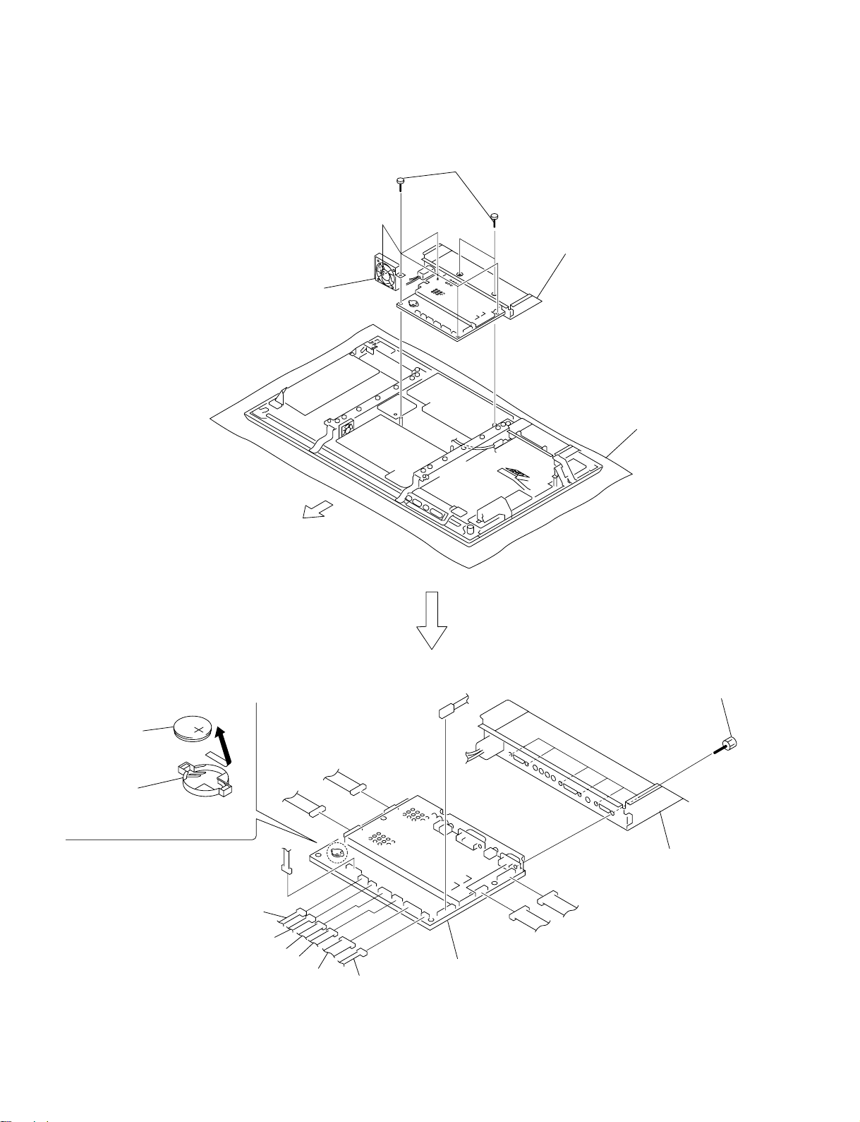
1-3-4. A (Main) Board
. Remove the rear cover assembly. (Refer to 1-3-2.)
2 DC fan,
Bracket
1 Seven screws
3 A (Main) board, Cover,
AC inlet
Conductive cushion
Lithium battery removal
Lithium battery
(CR2032)
Battery holder
Remove the lithium battery in the
direction of arrow.
CN23
CN3
CN22
UPPER
SIDE
CN9
CN19
CN8
CN501
4 Six screws
CN7
CN1
5 Cover, AC inlet
CN6
CN2
6 A (Main) board
CN15
1-4
PFM-42V1/42V1A/42V1E/42V1P
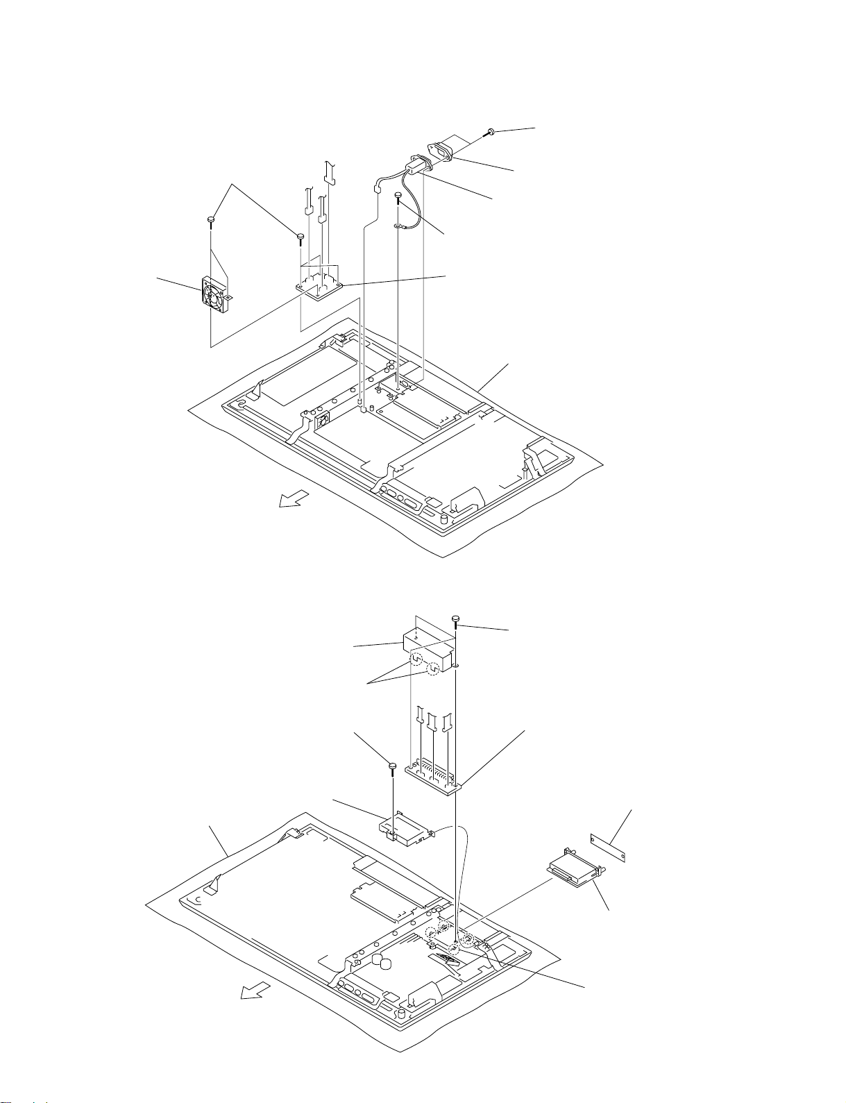
1-3-5. L (Audio) Board and AC Inlet
. Remove the rear cover assembly. (Refer to 1-3-2.)
P301
1 Five screws
CN01
4 Two screws
6 Plug holder (A)
P302
2 DC Fan,
Bracket
UPPER
SIDE
P303
1-3-6. I (Connection) Board
. Remove the OP-1 board and blank panel. (Refer to 1-3-1.)
. Remove the rear cover assembly. (Refer to 1-3-2.)
6 Shield
7 AC inlet
5 Screw
3 L (Audio) board
Conductive cushion
4 Three screws
Conductive cushion
PFM-42V1/42V1A/42V1E/42V1P
5 Remove soldering from
the two points
3 Shield
UPPER
SIDE
1 Screw
P303
P304
P305
7 I (Connection) board
Blank panel
PFM-42V1E (Only)
OP-1 Board
PFM-42V1, PFM-42V1P,
PFM-42V1A
2 Four claws
1-5
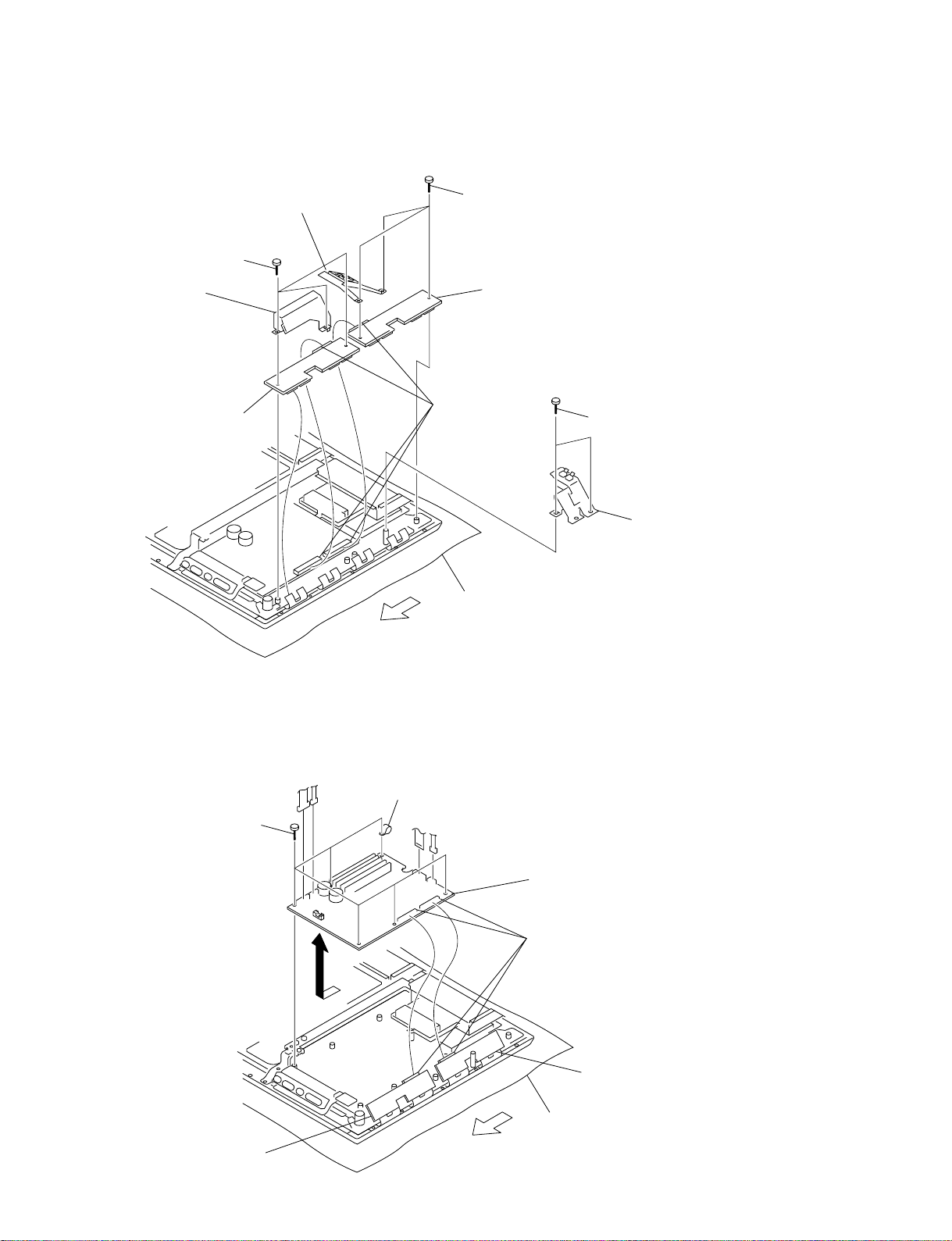
1-3-7. T-R/T-L (SP), TEMP, H2 (User Control) Boards
. Remove the rear cover assembly. (Refer to 1-3-2.)
6 TEMP board
4 T-L (SP) board
5 Screw
CN501
P1201
7 Screw
3 Two screws
UPPER
SIDE
CN501
8 TEMP board
9 Screw
CN501
0 TEMP board
1 Two screws
Conductive cushion
2 T-R (SP) board
P1201
1-6
!= Seven claws
P1101
!- Screw
![ Multi button
UPPER
SIDE
!] H-2 (User Control) board
Conductive cushion
PFM-42V1/42V1A/42V1E/42V1P
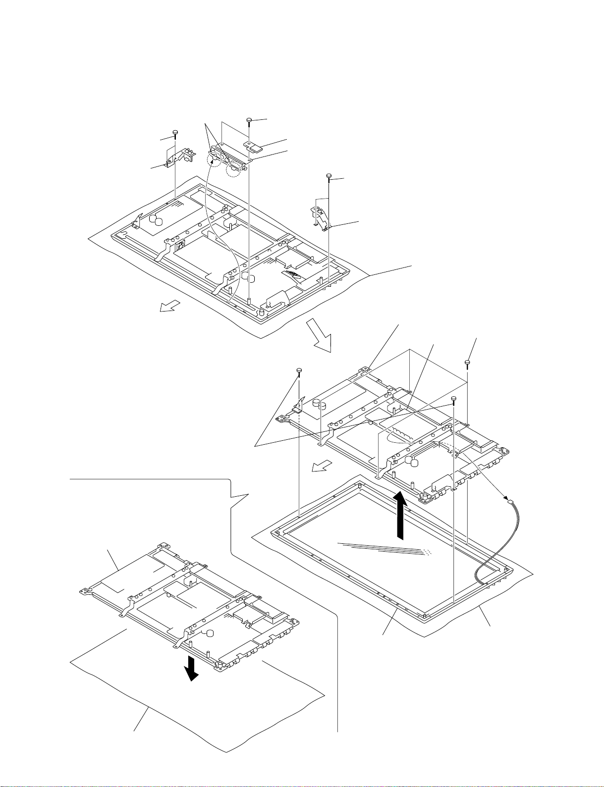
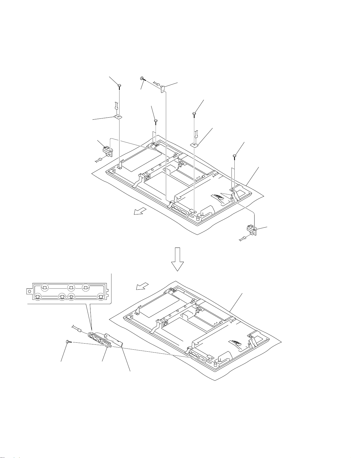
1-3-8. Bezel Assembly-1
. Remove the rear cover assembly. (Refer to 1-3-2.)
7 Two screws
8 T-L (SP) board,
Bracket
UPPER
SIDE
3 Two claws
1 Two screws
2 TEMP board, Bracket
4 H2 (User control) board,
Multi button, Multi button bracket
5 Two screws
6 T-R (SP) board,
Bracket
Conductive cushion
!- Main chassis
A (Main) board
0 Four screws
9 Two screws
Note : When removing the main chassis,
be sure that the two persons or
more must work together for removal.
Place the removed main chassis on the
conductive cushion.
Main chassis
Conductive cushion
UPPER
SIDE
!= Bezel assembly,
Filter glass
CN22
Conductive cushion
PFM-42V1/42V1A/42V1E/42V1P
1-7
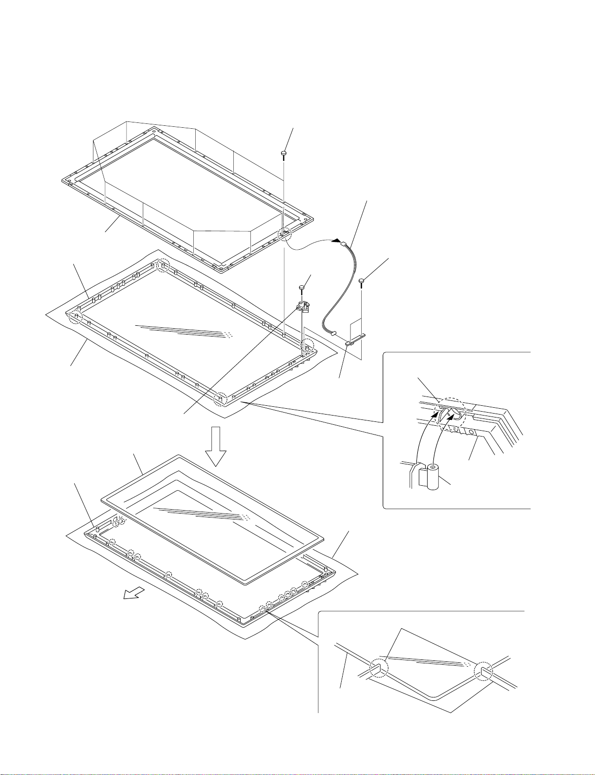
1-3-9. Bezel Assembly-2
. Remove the bezel assembly-1. (Refer to 1-3-8.)
3 Frame front assembly
8 Bezel assembly,
Filter glass
1 Ten screws
2 Remove the harness
in the direction of the arrow.
Note: Be careful not to damage the harness.
4 Two screws
6 Screw
P1201
Precaution during frame front
assembly installation
Conductive cushion
0 Bezel assembly
UPPER
SIDE
When installing frame front assembly
insert it in the groove.
5 H1 (SW) board
7 Power button
9 Filter glass
Frame front assembly
Bezel assembly
Conductive cushion
Precaution during filter glass installation
When installing bezel assembly insert it in the groove.
1-8
Filter glass
Bezel assembly
PFM-42V1/42V1A/42V1E/42V1P
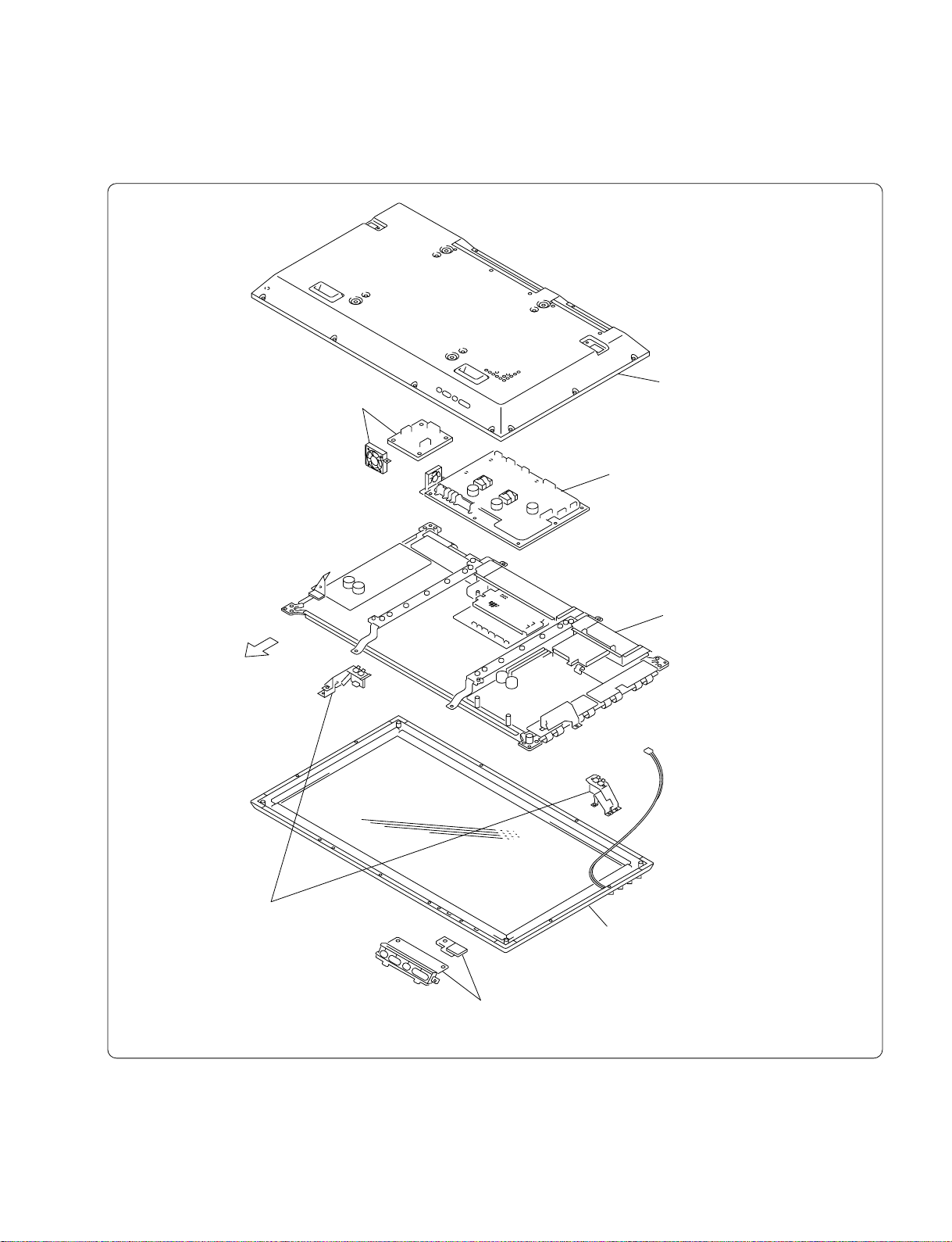
1-3-10.Plasma Display Panel-1
. To remove the plasma display panel, remove the related parts beforehand.
3 Remove the L (Audio) board,
DC fan, bracket. (Refer to 1-3-5.)
UPPER
SIDE
1 Remove the rear cover assembly.
(Refer to 1-3-2.)
2 Remove the G (Power) board, DC fan.
(Refer to 1-3-3.)
7 Plasma display panel-1
4 Remove the T-L, T-R (SP) boards.
(Refer to 1-3-8.)
PFM-42V1/42V1A/42V1E/42V1P
6 Remove the bezel assembly, Filter glass,
H1 (SW) board. (Refer to 1-3-8.)
5 Remove the H2 (User control), TEMP boards,
Multi button. (Refer to 1-3-8.)
1-9
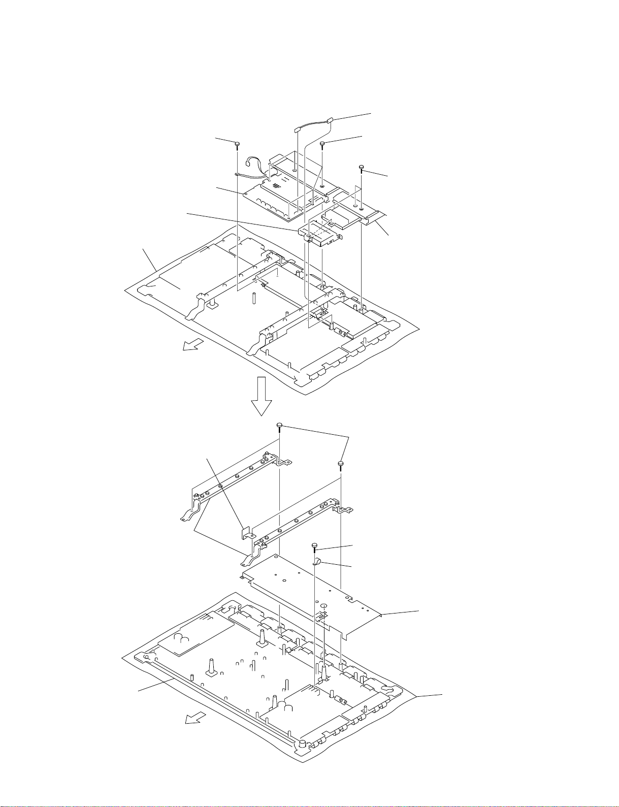
1-3-11.Plasma Display Panel-2
. Remove the plasma display panel-1. (Refer to 1-3-10.)
P31
4 Connector assembly (31P)
7 A (Main) board,
Cover, AC inlet
2 Shield
Conductive cushion
UPPER
SIDE
6 Screw
J501
5 Five screws
1 Three screws
3 I (Connection) board, Cover,
OP-1 board
0 Two module frame metals,
Support frame metals
!] Plasma display panel
8 Four screws
9 TEMP board, Bracket
!- Screw
!= Cable holder
1-3-12.YDB, YDT Boards
. Remove the rear cover assembly. (Refer to 1-3-2.)
4 Three screws
5 Bracket
9 YDT board
6 DC fan,
Bracket
P1
P3
P2
P4
P3
P4
UPPER
SIDE
P5
P8
P7
P6
7 Board to board
3 Three screws
8 YDB board
1 Two screws
2 T-R (SP) board,
Bracket
Conductive cushion
1-3-13.Y-SUS Board
. Remove the YDB, YDT boards. (Refer to 1-3-12.)
P6
P5
1 Six screws
YDT board
2 Cable holder
P1
P4
P3
P2
4 Remove the Y-SUS board
in the direction of the arrow.
3 Board to board
YDB board
Conductive cushion
UPPER
SIDE
PFM-42V1/42V1A/42V1E/42V1P
1-11
 Loading...