

Sony PFM-42V1, PFM-42V1N, PFM-42V1P, PFM-42V1E, PFM-42V1A Operating Instructions Manual
PFM-42V1/42V1E/42V1N/42V1P/42V1A
4-097-590-03 (1)
Flat Panel Display
取扱説明書
Operating Instructions
Mode d’emploi
Bedienungsanleitung
Manual de instrucciones
Istruzioni per l’uso
お買い上げいただきありがとうございます。
この取扱説明書には、事故を防ぐための重要な注意事項と製品の取り扱
いかたを示してあります。この取扱説明書をよくお読みのうえ、製品を
安全にお使いください。お読みになったあとは、いつでも見られるとこ
ろに必ず保管してください。
電気製品は安全のための注意事項を守らないと、
火災や人身事故になることがあります。
JP
GB
FR
DE
ES
IT
CS
PFM-42V1/42V1E/42V1N/42V1P/
42V1A
2003 Sony Corporation
WARNING
Owner’s Record
The model and serial numbers are located on the rear.
Record the model and serial numbers in the spaces
provided below. Refer to these numbers whenever you call
upon your Sony dealer regarding this product.
Model No. Serial No.
To prevent fire or shock hazard, do not
expose the unit to rain or moisture.
To avoid electrical shock, do not open the
cabinet. Refer servicing to qualified
personnel only.
On transportation
When you carry the display unit, hold the unit itself, not the
speakers. If you fail to do so, the speakers may come out of
the unit and the unit may fall. This can cause injury.
For customers in the U.S.A.
If you have any questions about this product, you may
call; Sony Customer Information Services Center
1-800-222-7669 or http://www.sony.com/
This equipment has been tested and found to comply with
the limits for a Class B digital device, pursuant to Part 15 of
the FCC Rules. These limits are designed to provide
reasonable protection against harmful interference in a
residential installation. This equipment generates, uses, and
can radiate radio frequency energy and, if not installed and
used in accordance with the instructions, may cause harmful
interference to radio communications. However, there is no
guarantee that interference will not occur in a particular
installation. If this equipment does cause harmful
interference to radio or television reception, which can be
determined by turning the equipment off and on, the user is
encouraged to try to correct the interference by one or more
of the following measures:
• Reorient or relocate the receiving antenna.
• Increase the separation between the equipment and
receiver.
• Connect the equipment into an outlet on a circuit different
from that to which the receiver is connected.
• Consult the dealer or an experienced radio/TV technician
for help.
You are cautioned that any changes or modifications not
expressly approved in this manual could void your authority
to operate this equipment.
For customers in Canada
This class B digital apparatus complies with Canadian
ICES-003.
Voor de klanten in Nederland
Declaration of Conformity
Trade Name: SONY
Model: PFM-42V1/PFM-42V1P/
PFM-42V1A
Responsible Party: Sony Electronics Inc.
Address: 16450 W. Bernardo Dr,
San Diego, CA 92127 U.S.A.
Telephone Number: 858-942-2230
This device complies with Part 15 of the FCC Rules.
Operation is subject to the following two conditions: (1) This
device may not cause harmful interference, and (2) this
device must accept any interference received, including
interference that may cause undesired operation.
• Dit apparaat bevat een vast ingebouwde batterij die niet
vervangen hoeft te worden tijdens de levensduur van het
apparaat.
• Raadpleeg uw leverancier indien de batterij toch
vervangen moet worden. De batterij mag alleen
vervangen worden door vakbekwaam servicepersoneel.
• Gooi de batterij niet weg maar lever deze in als klein
chemisch afval (KCA).
• Lever het apparaat aan het einde van de
levensduur in voor recycling, de batterij zal
dan op correcte wijze verwerkt worden.
The socket-outlet should be installed near the equipment
and be easily accessible.
NL
Caution
Risk of explosion if batteries are replaced by an incorrect
type. Dispose of used batteries according to the instructions.
2 (GB)

Table of Contents
Precautions ............................................................... 5 (GB)
Features..................................................................... 6 (GB)
Location and Function of Parts and Controls ....... 7 (GB)
Front / Rear / Bottom ............................................... 7 (GB)
1 (standby) Switch / Indicator Section ................... 8 (GB)
Control Button Section (Top) .................................. 8 (GB)
Connector Panel ....................................................... 9 (GB)
Remote Commander RM-971................................ 11 (GB)
Caution .................................................................... 13 (GB)
Connections............................................................ 15 (GB)
Connecting the Speakers........................................ 15 (GB)
Connecting the AC Power Cord ............................ 15 (GB)
Connection Example.............................................. 16 (GB)
Using On-screen Menus ........................................ 18 (GB)
Operating Through Menus..................................... 18 (GB)
Menu Guide ........................................................... 18 (GB)
Watching the Picture.............................................. 26 (GB)
Switching the Input Signal..................................... 26 (GB)
Input Signal, Picture Mode and Display Status
Information ....................................................... 27 (GB)
Switching the Display Mode.................................. 29 (GB)
Energy Saving Function......................................... 29 (GB)
Selecting Image Quality ......................................... 30 (GB)
Adjusting the Picture ............................................. 30 (GB)
Adjusting the Contrast, Brightness, Chroma,
and Phase, etc.................................................... 30 (GB)
Restoring the Adjust Picture Menu Items to
Their Original Settings ..................................... 33 (GB)
Picture Enlargement............................................... 34 (GB)
Setting Auto Wide ................................................. 34 (GB)
Setting the Wide Mode .......................................... 35 (GB)
GB
English
Resizing and Positioning the Picture ................... 36 (GB)
Resizing the Picture ............................................... 36 (GB)
Adjusting the Picture Position ............................... 36 (GB)
Adjusting the Pixels ............................................... 37 (GB)
Restoring the Screen Control Menu
Adjustment Values............................................ 37 (GB)
3 (GB)

Viewing two pictures at the same time................. 38 (GB)
Activating a picture................................................ 38 (GB)
Switching the position of the two pictures............. 38 (GB)
Zooming in on a picture......................................... 39 (GB)
Adjusting the Sound Quality ................................. 39 (GB)
Adjusting the Treble, Bass, and Balance, etc. ....... 39 (GB)
Restoring the Adjust Sound Menu Items to
Their Original Settings ..................................... 40 (GB)
Using the Memory Function .................................. 40 (GB)
Storing the Current Setting .................................... 40 (GB)
Calling Up a Stored Setting ................................... 41 (GB)
Selecting the On-screen Language ...................... 42 (GB)
Screen Saver Function........................................... 42 (GB)
Reversing the Color Tones of the Image ............... 42 (GB)
Changing the Image Position Automatically ......... 44 (GB)
Adjusting Color Matrix ........................................... 44 (GB)
Controlling Power On/Off Automatically (Timer
Function)............................................................. 45 (GB)
Sleep Function ....................................................... 45 (GB)
Adjusting the time.................................................. 46 (GB)
Displaying the time ................................................ 46 (GB)
On/Off Timer Function .......................................... 47 (GB)
Power Saving Function .......................................... 48 (GB)
Operating a Specific Display With the Remote
Commander ........................................................ 49 (GB)
Using Other Remote Commander Models ........... 50 (GB)
Specifications ......................................................... 51 (GB)
4 (GB)

Precautions
On safety
•A nameplate indicating operating voltage, power
consumption, etc. is located on the rear of the unit.
•Should any solid object or liquid fall into the cabinet,
unplug the unit and have it checked by qualified
personnel before operating it any further.
•Unplug the unit from the wall outlet if it is not to be
used for several days or more.
•To disconnect the AC power cord, pull it out by
grasping the plug. Never pull the cord itself.
•When you install the unit on the floor, be sure to use
the optional stand.
On installation
•Allow adequate air circulation to prevent internal
heat build-up. Do not place the unit on surfaces
(rugs, blankets, etc.) or near materials (curtains,
draperies) that may block the ventilation holes.
•Do not install the unit in a location near heat sources
such as radiators or air ducts, or in a place subject to
direct sunlight, excessive dust, mechanical vibration
or shock.
•When you install multiple equipment with the unit,
the following problems, such as malfunction of the
Remote Commander, noisy picture, noisy sound,
may occur depending on the position of the unit and
other equipment.
•Communication problems may occur if the infrared
communication equipment (e.g., infrared cordless
headphones or microphones) is used near the display.
Please use headphones or microphones other than
infrared cordless headphones or microphones. If you
must use the infrared communication equipment,
move it away from the display until the noise is
eliminated, or move the transmitter and receiver of
the infrared communication equipment closer
together.
Precautions
•Because of the way it is made, when this plasma
display panel is used in places with low air pressure,
such as at high altitudes, a buzzing or humming
noise may emanate from the unit.
•If you continue to display the same image on the
screen for a long period of time, part of that image
may burn into the screen and leave a ghosting image
behind. To avoid this, please use the screen saver
function provided to equalize use over the entire
screen. If ghosting occurs, use the screen saver
function, or use video or imaging softwares to
provide constant movement on the screen. If slight
ghosting (image burn-in) occurs, it may become less
conspicuous, but once burn-in occurs, it will never
completely disappear.
•To protect the plasma display, this unit will not
accept commands from the Remote Commander or
from the function buttons on the unit for a certain
period of time after the unit has been switched ON/
STANDBY. After one of these operations, wait
about 8 seconds before entering a command.
On cleaning
To keep the unit looking brand-new, clean it
periodically with a mild detergent solution. Never use
strong solvents such as thinner or benzine, or abrasive
cleansers since these will damage the cabinet. As a
safety precaution, unplug the unit before cleaning it.
Notes on handling and cleaning the display
panel
The display panel’s special surface finish should be
treated with care when cleaning or handling the TV.
When cleaning it, use a soft cleaning cloth to avoid
touching the panel directly.
On repacking
Do not throw away the carton and packing materials.
They make an ideal container in which to transport the
unit. When shipping the unit, repack it as illustrated
on the carton.
On the PDP (Plasma Display Panel)
•You may see some bright spots of red, blue or green,
or dark spots appearing on the screen. These do not
indicate a malfunction. Although the plasma display
panel is manufactured with extremely high precision
technology, it can generate a few dark or bright
pixels. Dark spots on the edge of the screen, or
striped color and brightness irregularities do not
indicate a malfunction.
•Do not display the same still image on the screen for
a long time. Otherwise, an afterimage or ghost may
appear on a part of the panel. Use the screen saver
function to equalize use of the screen display.
If you have any questions on this unit, contact your
authorized Sony dealers.
5 (GB)
Features
Features
The PFM-42V1 Series is 16:9 42-inch flat panel
display utilizing a PDP (Plasma Display Panel), which
can accept various types of signals with the built-in
scan converter.
Bright and clear image
The PFM-42V1 Series utilizes a bright plasma display
panel with 852 dots × 480 lines. This allows bright
and clear image reproduction from a variety of image
sources.
Digital high picture quality circuit
Consistent digital processing of all image signals
results in faithful reproduction of high-quality images.
Audio amp and speaker out sockets
This display is equipped with high sound quality
digital amps, which when combined with optional
speakers, provides you with effective presentation.
Other features
•Speaker out (L/R) sockets
•Control S (IN/OUT)
•DVI-D input* (Does not support copy protection.)
•Displays an HDTV signal with a tri-level sync signal.
•Three dimensional comb filter for NTSC Y/C
separation
•Line correlation comb filter for PAL Y/C separation.
•Automatic input signal detection with on-screen
indication
•Windows
1)
98/2000/ME/XP PnP (Plug and Play)
compatibility
•Dynamic picture function
•On-screen menu for various adjustments and settings
•On-screen display in six languages for user-friendly
access (Languages: English, German, French, Italian,
Spanish, and Japanese)
•Fine adjustment of image size and position
•Memory function for storage of up to twenty picture
settings
•ID control
•Remote (RS-232C) connector (D-sub 9-pin)
•Accepts commands from infrared Sony Remote
Commanders using SIRCS code
•Closed caption decoder
•Screen saver to reduce afterimage or ghosting
•An option slot is in place for future expansion.
The slot-in optional adaptor allows for quick and
easy system upgrades.
* Except for the PFM-42V1N
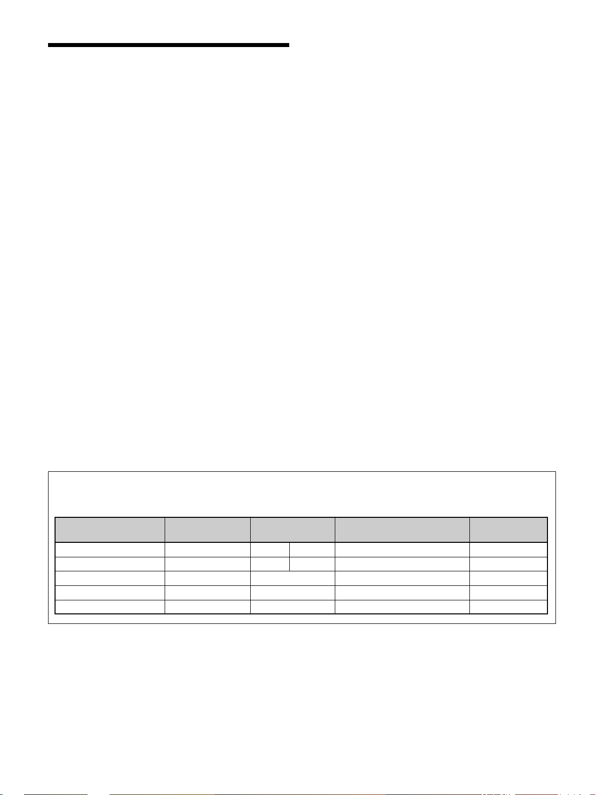
Warning on power connection
Use the proper power cord for your local power supply.
PFM-42V1 Series
United States, Continental United Kingdom, Ireland, Japan
Canada Europe Australia, New Zealand
Plug type VM0233 COX-07 636 —
Female end VM0089 COX-02 VM0310B VM0303B VM1313
Cord type SVT H05VV-F CEE (13) 53rd (O.C) HVCTF
Minimum cord set rating 10A/125V 10A/250V 10A/250V 10A/125V
Safety approval UL/CSA VDE VDE DENAN-HO
a) Note: Use an appropriate rating plug which complies with local regulations.
a)
VM1296
.........................................................................................................................................................................................................
1) Windows is a registered trademark of the Microsoft Corporation (U.S.A. and other countries).
6 (GB)
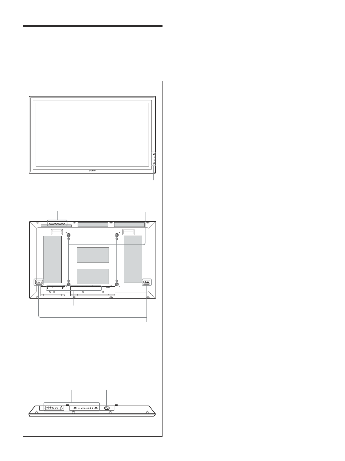
Location and Function
1
2 3
56
of Parts and Controls
Front / Rear / Bottom
Location and Function of Parts and Controls
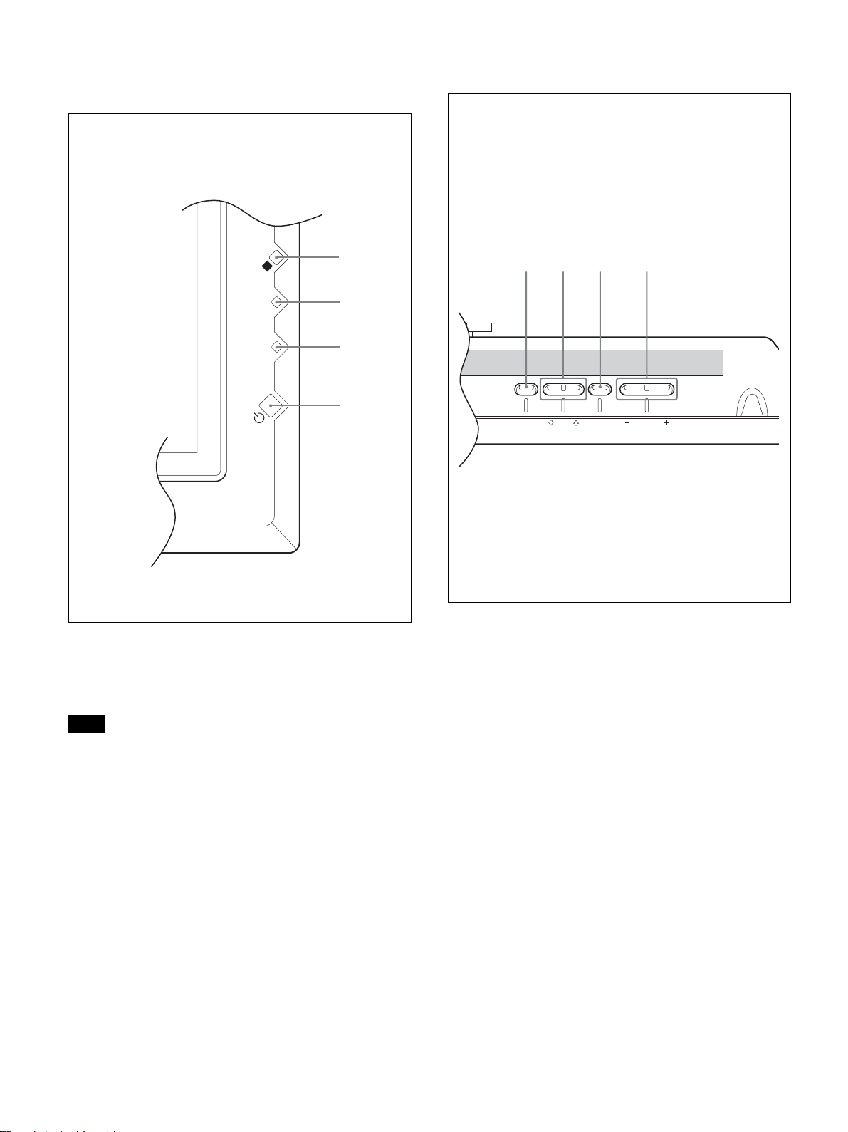
1 1 (standby) switch / indicator section
For details on the 1 (standby) switch / indicator section,
see “1 (standby) Switch / Indicator Section” on page 8
(GB).
2 Control button section
For details on the control button section, see “Control
Button Section (Top)” on page 8 (GB).
Front
Rear
3 Stand installation hooks
Use these hooks to install the stand (not supplied).
4 SPEAKER Socket
Connects the speakers (not supplied) to this socket to
output the audio matching the signal displayed on the
screen.
ON
STANDBY
5 Connector panel
For details on the connector panel, see “Connector Panel”
on page 9 (GB).
6 - AC IN socket
Connect the supplied AC power cord to this socket
and to a wall outlet. Once you connect the AC power
cord, the STANDBY indicator lights up in red and the
display goes into the standby mode.
For more details on the power cord, see “Connecting the
AC Power Cord” on page 15 (GB).
56
The shaded areas shown in the illustration above are all
ventilation holes.
Bottom
4
7 (GB)
Location and Function of Parts and Controls
123 4
1 (standby) Switch / Indicator
Section
4
3
2
1
STANDB
N
O
Y
Control Button Section (Top)
MENU ENTER VOLUME
1 1 (standby) switch
Press to power on the display unit. Press again to
return to the standby mode.
Note
To protect the panel, a certain amount of time is
required to turn the unit ON/STANDBY. Wait about 8
seconds after one of these operations before pressing
this switch again.
2 STANDBY indicator
Lights up in red in the standby mode.
3 ON indicator
Lights up in green when the display unit is powered
on.
4 Remote control detector
Receives the signals from the Remote Commander.
1 MENU button
Press to show menus. Press again to hide them.
To use the MENU button to return to the previous menu
level, see “Initial Setup menu” on page 23 (GB).
2 m/M buttons
Press to move the cursor (yellow) to an item you want
to select or to adjust a value in a menu.
3 ENTER button
Press to set your choice.
4 VOLUME +/– button
Press to adjust the speaker volume.
8 (GB)
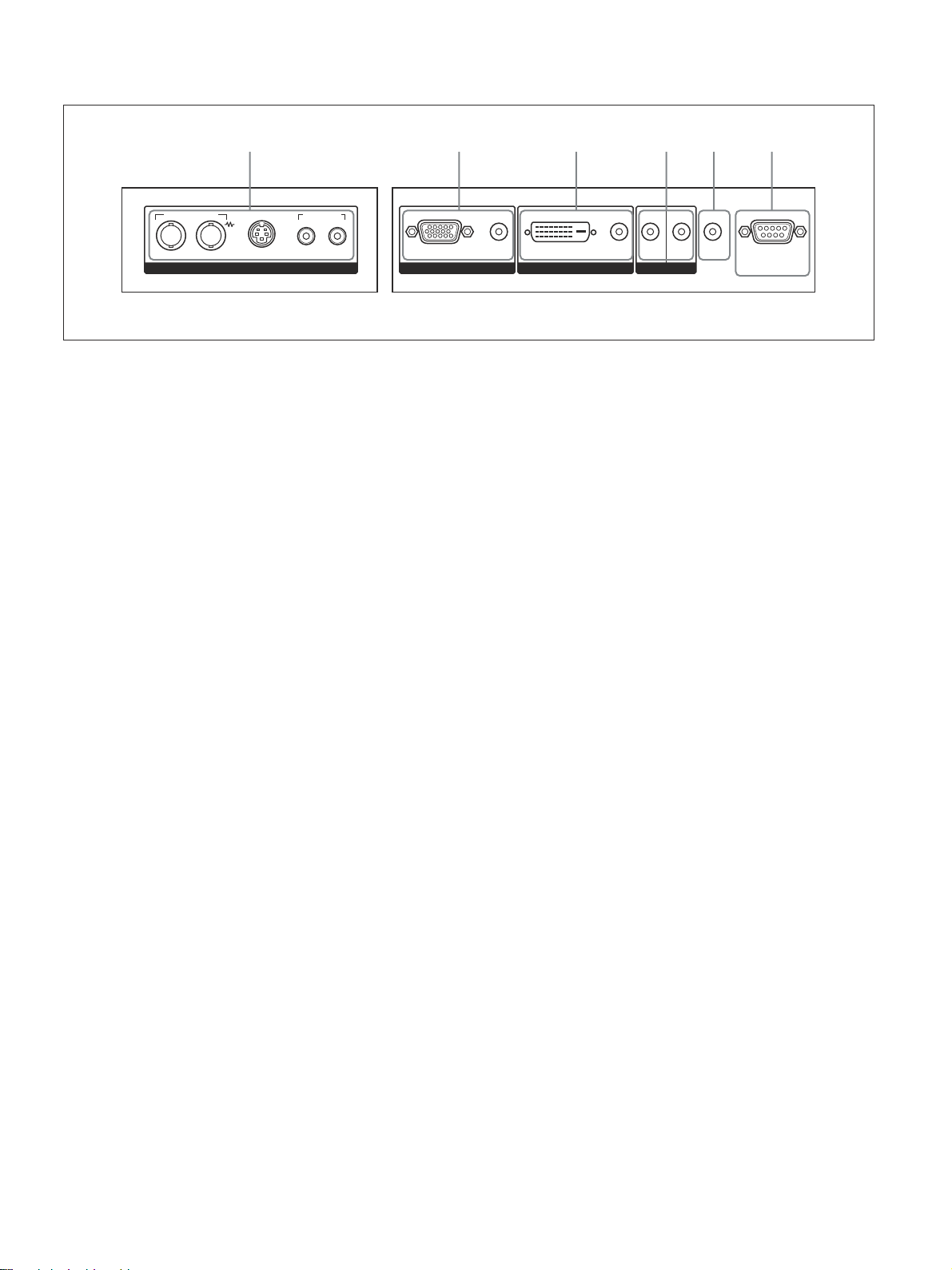
Connector Panel
123456
Location and Function of Parts and Controls
AUDIO INCOMPOSITE
IN OUT
Y/C IN
VIDEO
L R
RGB/YUV
1 VIDEO connectors
The PFM-42V1E and 42V1N are not equipped with
VIDEO connectors. For these models, composite
video and Y/C input can be input when the Video
Input Adaptor BKM-V10 (not supplied) is installed in
the display.
COMPOSITE IN (BNC) : Connects to the
composite video signal output of a piece of video
equipment.
COMPOSITE OUT (BNC) : Connects to the
composite video signal input of a piece of video
equipment.
Y/C IN (Mini DIN 4-pin) : Connects to the Y/C
signal output of a piece of video equipment.
AUDIO IN L/R (Pinjack) : Inputs an audio signal.
Connects to the audio output of a piece of video
equipment.
2 INPUT1 (ANALOG RGB/YUV IN) connectors
RGB/YUV (D-sub 15-pin) : Connects to the analog
RGB signal or component (YUV) signal output of
a piece of video equipment.
AUDIO (Stereo minijack) : Inputs an audio signal.
Connects to the audio output of a piece of video
equipment.
INPUT 1
AUDIO
DVI IN OUT
INPUT 2
AUDIO
CONTROL S
AUDIO
OUT
REMOTE
4 CONTROL S IN/OUT (Control S Signal Input/
Output) Connector (Minijack)
You can control multiple devices with a single remote
commander when connected to the CONTROL S
connector of a video device or other display. Connect the
CONTROL S OUT connector on this display to the
CONTROL S IN connector of the other device, and
connect the CONTROL S IN connector on this display
to the CONTROL S OUT connector of the other device.
5 AUDIO OUT (Stereo minijack)
Outputs an audio of the signal currently indicated on
the screen.
6 REMOTE (RS-232C) connector (D-sub 9-pin)
This connector allows remote control of the display
using the RS-232C protocol. For details, contact your
authorized Sony dealers.
* The PFM-42V1N is not equipped with the INPUT2
connectors.
3 INPUT2 (DIGITAL RGB IN) connectors *
DVI : Connects to the digital RGB signal output of a
computer.
AUDIO (Stereo minijack) : Inputs an audio signal.
Connects to the audio output of a computer.
Connect the supplied cable to the DVI connector.
9 (GB)
Location and Function of Parts and Controls
1
1
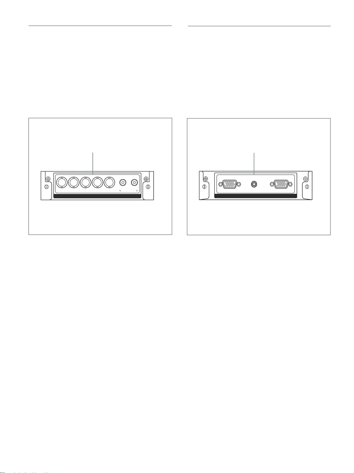
Component/RGB Input Adaptor BKM-V11
(not supplied)
The VIDEO connectors are slot-in connectors. You
can replace the VIDEO connectors (Video Input
Adaptor BKM-V10) with a Component/RGB Input
Adaptor BKM-V11 (not supplied.)
For the PFM-42V1E and 42V1N, you can install
either BKM-V11, BKM-V10 or BKM-V12.
For details on installation, contact your authorized Sony
dealer.
Y/G U/B V/R HD VD
YUV/RGB IN
LR
AUDIO IN
RGB/Component Active Through Adaptor
BKM-V12 (not supplied)
The VIDEO connectors are slot-in connectors. You
can replace the VIDEO connectors (Video Input
Adaptor BKM-V10) with an RGB/Component Active
Through Adaptor BKM-V12 (not supplied.)
For the PFM-42V1E and 42V1N, you can install
either BKM-V11, BKM-V10, or BKM-V12.
For details on installation, contact your authorized Sony
dealer.
OUTAUDIO ININ
RGB/YUV ACTIVE THROUGH
1 YUV/RGB IN connectors
YUV/RGB IN (BNC) : Connects to the analog RGB
signal or component (YUV) signal output of a
piece of video equipment.
AUDIO IN L/R (Pinjack) : Inputs an audio signal.
Connects to the audio output of a piece of video
equipment.
1 RGB/YUV ACTIVE THROUGH connectors
RGB/YUV IN (analog RGB/component signal
input) (D-sub 15-pin) : Connects to the analog
RGB signal or component (YUV) signal output of
a piece of video equipment or a computer.
AUDIO IN (Stereo minijack) : Inputs an audio
signal. Connects to the audio output of a piece of
video equipment or a computer.
RGB/YUV OUT (analog RGB/component signal
active through output) (D-sub 15-pin) : Outputs
the signal input through the RGB/YUV IN
(analog RGB/component signal input) connectors
on this adaptor.
10 (GB)
Location and Function of Parts and Controls
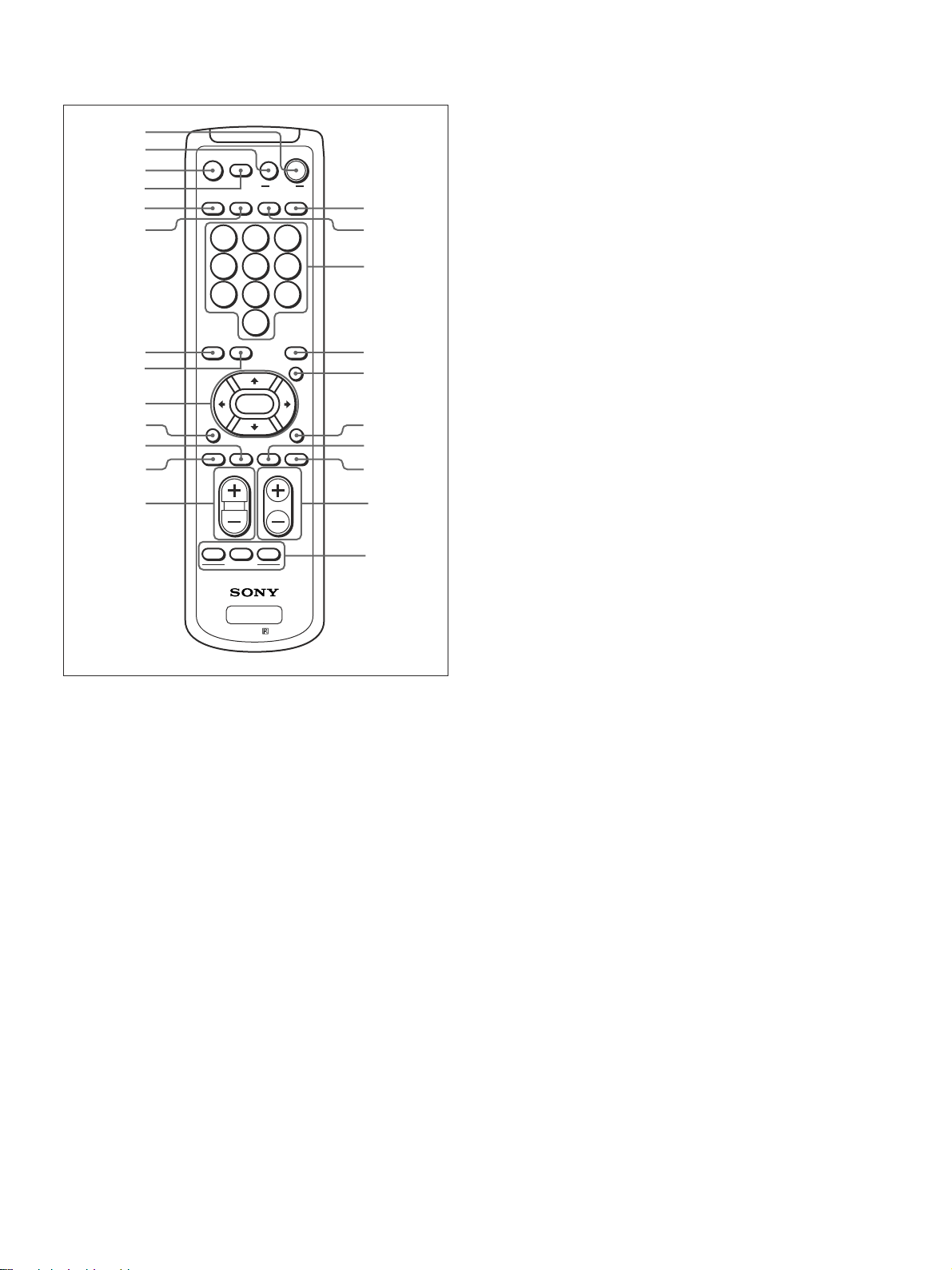
Remote Commander RM-971
1
2
3
4
5
6
7
8
9
0
qa
qs
qd
MUTING
DISPLAY STBY
INPUT 1 INPUT 2 VIDEO OPTION
POWER
123
456
7809
S/VIDEO ASPECT
RGB/YUV
ENTER
BRIGHT
H SHIFT V SHFT H SIZE
VOL CONTRAST
ON SET
OFF
ID MODE
PFM
RM-971
ON
MENU
CHROMA
VSIZE
qf
qg
qh
qj
qk
ql
w;
wa
ws
wd
7 RGB/YUV button
Press to select the format matching that of the input
signal connected to the INPUT1 connector. Each press
toggles between RGB and component (YUV).
8 S/VIDEO button
Press to select the signal input to the VIDEO
connectors. Each press toggles between COMPOSITE
IN and Y/C IN.
9 M/m/</,/ENTER buttons
The M/m/</, buttons move the menu cursor
(yellow) and set values, etc. Pressing the ENTER
button sets the selected menu or setting items.
q; BRIGHT button
Adjusts the brightness when Picture Mode is set to
any of “User1” to “User3.” Press this button, then
adjust the brightness with M/m or </, buttons 9.
qa V SHIFT button
Adjusts the vertical centering. Press this button, then
adjust the vertical centering with M/m or </, buttons
9.
qs H SHIFT button
Adjusts the horizontal centering. Press this button,
then adjust the horizontal centering with M/m or
</, buttons 9.
1 POWER ON switch
Press to power on the display.
2 STANDBY button
Press to change the display to the standby mode.
3 MUTING button
Press to mute the sound. Press again to restore sound.
4 DISPLAY button
Press to display the input signal information and the
picture mode on the screen. Press again to hide them.
If this displayed information is left undisturbed for a
short time, it will disappear automatically.
5 INPUT1 button
Press to select the signal input to the INPUT1
connectors.
6 INPUT2 button
Press to select the signal input to the INPUT2
connectors.
qd VOLUME +/– button
Press to adjust the volume.
qf OPTION button
Selects the signal input to an optional adaptor (except
BKM-V10) when you install one in the unit.
qg VIDEO button
Press to select the signal input to the COMPOSITE IN
or Y/C IN of the VIDEO connectors.
qh Number buttons
Press to enter index numbers.
qj ASPECT button
Press to change the aspect ratio (Wide Mode).
qk MENU button
Press to show menus. Press again to hide them.
To use the MENU button to return to the previous menu
level, see “Initial Setup menu” on page 23 (GB).
ql CHROMA button
Adjusts the chroma when the picture mode is set to
any of “User1” to “User3.” Press this button and
adjust the chroma with the M/m or </, buttons 9.
11 (GB)
Location and Function of Parts and Controls
e
E
E
e
w; H SIZE button
Adjusts the horizontal picture size. Press this button,
then adjust the horizontal picture size with M/m or
</, buttons 9.
wa V SIZE button
Adjusts the vertical picture size. Press this button,
then adjust the vertical picture size with M/m or </
, buttons 9.
ws CONTRAST +/– button
Adjusts the contrast when Picture Mode is set to any
of “User1” to “User3.”
wd ID MODE (ON/SET/OFF) buttons
Press ON to show an index number on the screen.
Enter the index number of the display you want to
operate with Number buttons qh, then press SET.
Press OFF to return to the normal mode.
For details on the index numbers, see “Operating a
Specific Display With the Remote Commander” on page
49 (GB).
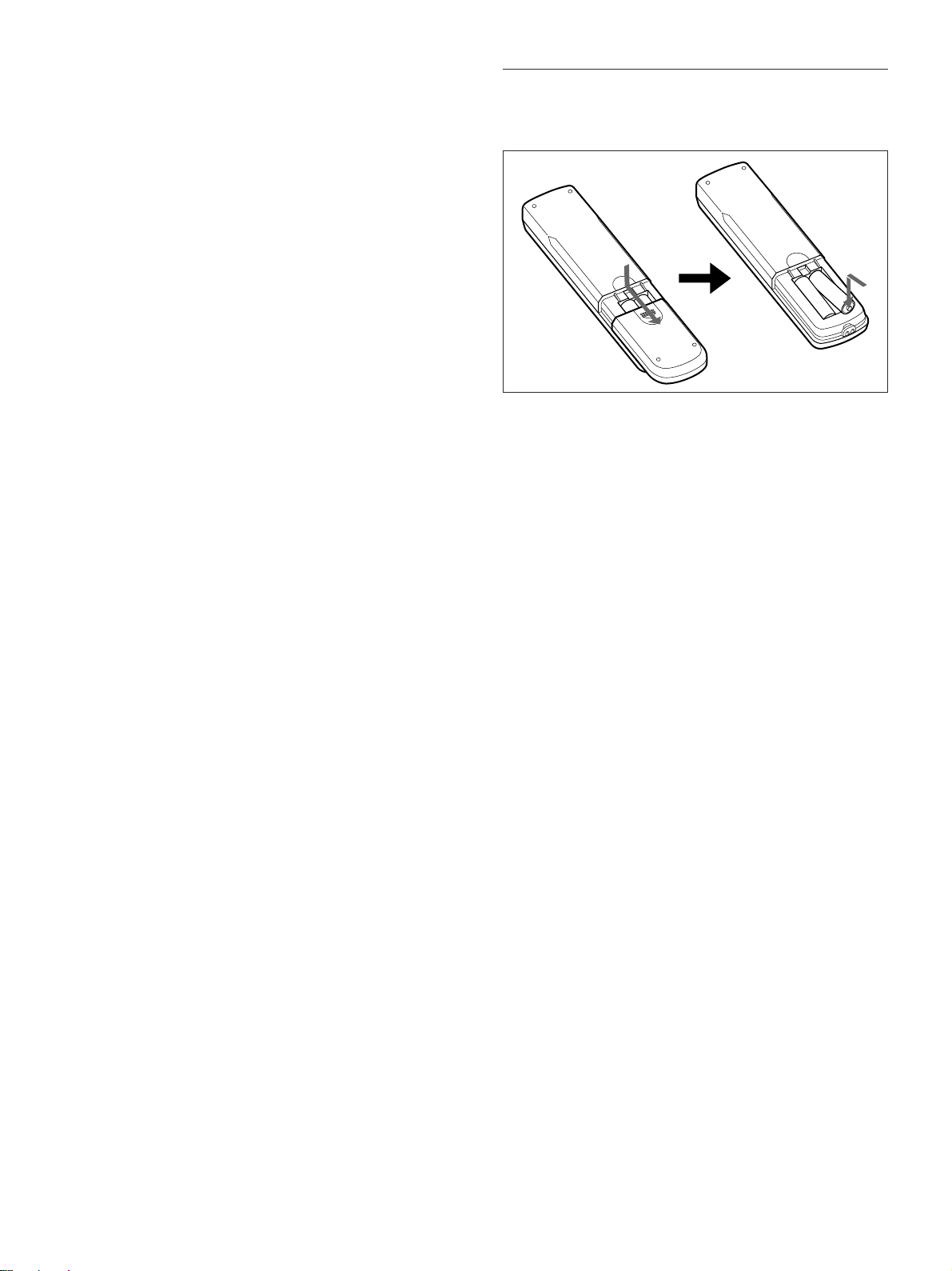
Installing batteries
Insert two size AA (R6) batteries in correct polarity.
Be sure to
install the
negative <
end first.
•In normal operation, batteries will last up to half a
year. If the Remote Commander does not operate
properly, the batteries might be exhausted sooner.
Replace them with new ones.
•To avoid damage from possible battery leakage,
remove the batteries if you do not plan to use the
Remote Commander for a fairly long time.
–
Caution
Risk of explosion if batteries are replaced by an
incorrect type. Dispose of used batteries according to
the instructions.
When the Remote Commander does not work
Check that the STANDBY indicator lights up and the
Remote Mode in the Remote menu is not set to Off.
The Remote Commander operates the display only
when both of the two conditions below are met.
•The display is turned on, or it is in the standby mode.
•The Remote Mode in the Remote menu is set to
“ON.”
For details on the Remote Mode, see “Remote menu” on
page 24 (GB).
12 (GB)
Caution
Caution
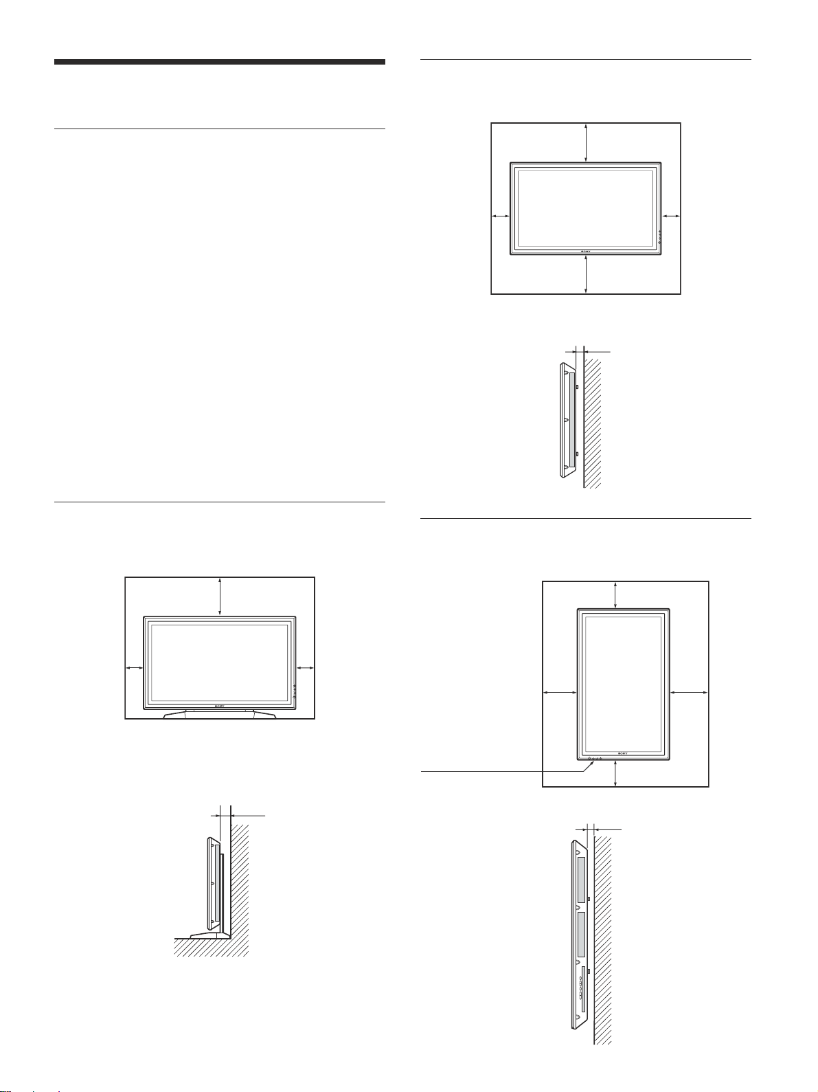
When mounting the display horizontally
Front
Provide an ample amount of space
around the display
•When you use the display, make sure there is more
space around the display than that shown in the
figure below. This will allow for proper ventilation.
•The ambient temperature must be 0 °C to +35 °C
(32 °F to 95 °F).
•When installing the display horizontally, use the
display stand SU-42B (not supplied) as a stand.
•Regarding the installation of hardware such as
brackets, screws, or bolts, we cannot specify the
products. Actual installation is up to the authorized
local dealers. Consult with qualified Sony personnel
for installation.
•While the unit is on, a certain amount of heat builds
up inside. This can cause burns. Avoid touching the
top or rear of the unit when it is powered on or just
after it has entered standby mode.
When using the stand (not supplied)
Front
25 (9 7/8)
10
(4)
Units: cm (inches)
Side
10
(4)
25 (9
5 (2)
7
/8)
When mounting the display vertically
Front
Side
10
(4)
20 (7
10 (4)
5 (2)
10 (4)
10 (4)
25
7
/8)
(9
7
/8)
10
(4)
Make sure that
the 1 (standby)
switch is at the
bottom.
20
7
(7
/8)
Side
Units: cm (inches)
Units: cm (inches)
13 (GB)

Caution
Notes on Image Retention
If the 1 – 5 are displayed for an extended period of
time, image retention (afterimage) in areas of the
screen may result due to the characteristics of the
Plasma Display Panel. It is possible to reduce image
retention by following steps A – D.
Situations which can result in burn-in and
picture retention
1 Black bars at the top and bottom that appear
with a wide video source (Letter box picture)
2 Black bars to the left and right that appear with
a 4:3 video source (conventional TV broadcast)
3 Video game
4 DVD on-screen menu displays
5 On-screen menus, channel numbers, etc., of
connected equipment such as DSS, Cable
boxes, video decks, etc.
Precautions to avoid/reduce burn-in and
picture retention
A Use the automatic orbiting Screen Saver
function.
B Avoid displaying channel numbers, on-screen
menus etc., of connected equipment such as
DSS, Cable boxes, video decks, etc. To erase
channel numbers, on-screen menus, refer to the
user manual of connected equipment.
C Reduce brightness of the picture and/or display
video source in “Expd. 4:3” mode or “16:9”
mode.
D It is possible to reduce minor image retention
with the “Pic. Inversion” (Picture Inversion)
function of “Screen Saver,” however, you
cannot remove it once it has occurred.
Notes on the “Pic. Inversion (Picture
Inversion)” function of “Screen Saver”
If the displayed image appears as an image like a film
negative, “Pic.Inversion (Picture Inversion)” of
“Screen Saver” may be set to “Auto,” or “On.” To
return to a normal image, select “Off” or reset the
specified time in “Auto.”
Pic. Inversion (Picture Inversion) inverts the tint of
the picture (Example: white to black, black to white)
and corrects the image retention (afterimage) with
displayed image on. The image looks like a film
negative during picture inversion. This is not a
malfunction.
14 (GB)

Connections
Before you start
•First make sure that the power to each piece of
equipment is turned off.
•Use connecting cables suitable for the equipment to
be connected.
•The cable connectors should be fully inserted into
the jacks. A loose connection may cause hum and
other noise.
•To disconnect the cable, pull it out by grasping the
plug. Never pull the cable itself.
•Refer to the instruction manual of the equipment to
be connected.
•Insert the plug securely into the AC IN socket.
•Use one of the two AC plug holders (supplied) that
will securely hold the AC plug.
Connecting the Speakers
You can enjoy viewing with a greater sense of
presence by connecting speakers SS-SP20B (not
supplied). Please be sure to connect the speakers
correctly. For more details on connecting the
speakers, see the operating manual that came with the
speakers.
Connections
Connecting the AC Power Cord
1 Plug the AC power cord into the AC IN socket.
Then, attach the AC plug holder (supplied) to the
AC power cord.
AC IN socket
AC power cord
AC plug holder
2 Slide the AC plug holder over the cord until it
connects to the AC IN socket cover.
AC IN socket
cover
To remove the AC power cord
After squeezing the AC plug holder and freeing it,
grasp the plug and pull out the AC power cord.
15 (GB)
Connections
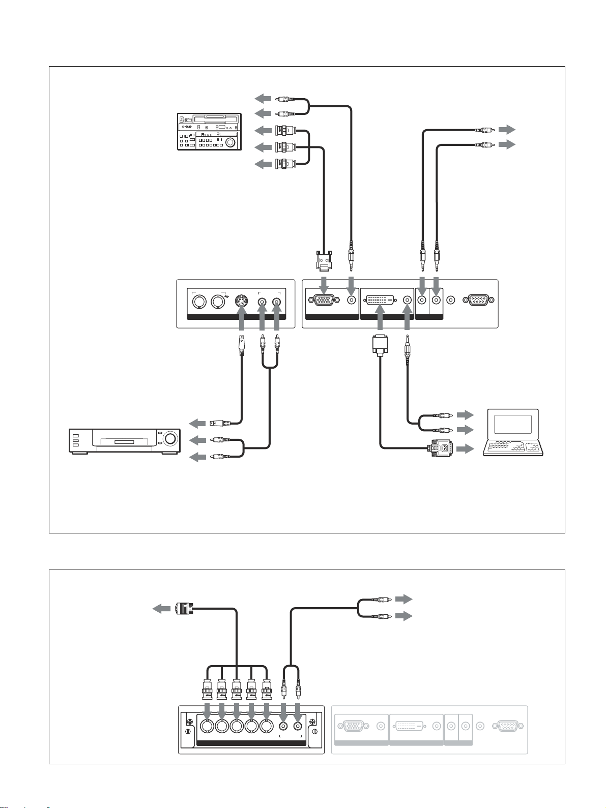
Connection Example
Betacam SP video
cassette recorder
IN OUT
VIDEO
to Y/C IN
to audio output
to component
signal output
AUDIO INCOMPOSITE
Y/C IN
R L
to RGB/YUV
to AUDIO IN
to CONTROL
S IN
to AUDIO
RGB/YUV
AUDIO
INPUT 1 INPUT 2
DVI IN OUT
to DVI to AUDIO
AUDIO
CONTROL S
to CONTROL S OUT
to CONTROL S IN
to CONTROL
S OUT
AUDIO
OUT
REMOTE
to audio
output
VCR, game machine,
to video
output
DVD player, etc.
to audio
output
to video
output
For the PFM-42V1E and 42V1N, the connection example applies when a Video Input Adaptor BKM-V10 is installed.
The PFM-42V1N is not equipped with the INPUT2 connectors.
When a Component/RGB Input Adaptor BKM-V11 is installed
to video
output
to YUV/RGB
IN
to AUDIO IN
to audio
output
Computer
16 (GB)
Y/G U/B V/R HD VD
YUV/RGB IN
LR
AUDIO IN
AUDIO
RGB/YUV
INPUT 1 INPUT 2
AUDIO
DVI IN OUT
CONTROL S
AUDIO
OUT
REMOTE
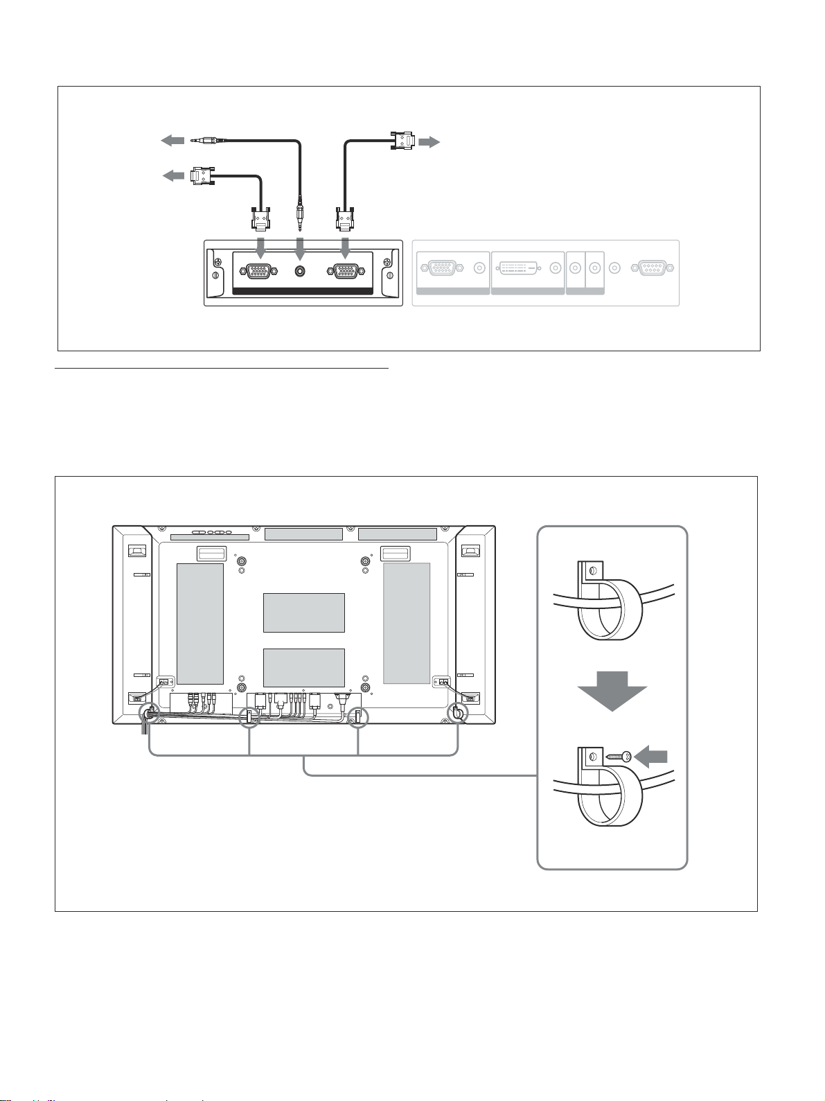
When an optional RGB/Component Active Through Adaptor BKM-V12 is installed
to audio
output
to video
input
to RGB/YUV
OUT
to video
output
to RGB/YUV
IN
to
AUDIO
IN
Connections
RGB/YUV ACTIVE THROUGH
OUTAUDIO ININ
Using the cable holders
You can neatly bundle the cables with the cable
holders (×4) provided. Attach the cable holders as
shown in the illustration below.
Rear
AUDIO
RGB/YUV
INPUT 1 INPUT 2
AUDIO
DVI IN OUT
CONTROL S
AUDIO
OUT
REMOTE
17 (GB)
 Loading...