

Page 1
PCM-200
Installation Instructions
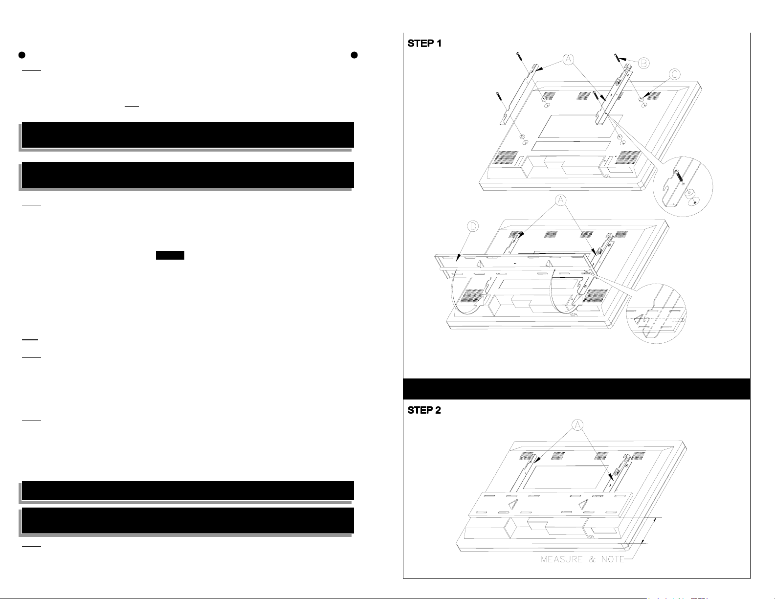
Step 1
Invert the display and place it on a soft and flat surface. Locate the mounting points on the back of the plasma display.
Identify the correct plasma bracket mounting hardware for your plasma display from the chart shown on the back of the
assembly manual and secure the (L) Left and (R) Right hand side mounting brackets to the plasma using the
corresponding hardware (supplied). Note
are facing to the left and right outside edges of the display.
Note: The KZ-32 backing must be taken off completely to remove the bottom stand. Unscrew the (4) 6 (mm)
screws from the stand. Re-install the backing with all chassis screws.
NOTE: Do not over tighten the bracket mounting screws as damage to the display internal mounting threads
could occur.
Step 2
Determine the desired height for the bottom edge of the display on the wall.
Temporarily slide the round steel rod portion of one of the universal (WP) wall plates fully into the bottom receiving slots
of the installed plasma mounting brackets. Measure the distance between the bottom outside edge of the plasma
display and the bottom outside edge of the lower wall mounting plate. Add the desired bottom edge height of the
display to the distance between the bottom edge of the wall plate and the bottom edge of the display to determine the
correct mounting height of the lower wall plate. Example: Overall desired height for the bottom outside of the display is
60". Difference between the bottom edge of the display and the bottom edge of the lower wall plate fully installed in the
lower receiving slots of the brackets is 4" means the lower wall plate bottom outside edge should be placed at 64" from
the floor (60" + 4" = 64"). Determine the desired wall location and its ability to properly support the weight of the display.
Locate and mark the dual 16" or 24" wood stud centers closest to the desired plasma placement area. Measure up
from the floor the proper distance to the bottom edge of the lower wall plate and mark a level reference line on the wall.
Place the lower wall plate bottom edge on the reference line and mark the best four (4) each wall plate lag bolt
mounting points through the wall plate slots on the wall. Install on a level the bottom wall plate with the wall plate
reference arrow pointing up to the wall using the (4) four 5/16" Lag bolts and flat washers (supplied).
The wall plate provides you with three (3) 16" stud center patterns and one (1) 24" stud center pattern to assist
Note:
you in your installation.
Step 3
With the lower wall plate securely installed and level with the floor place the “supplied” upper wall plate cardboard
placement template over the top and outside edges of the lower wall plate. Place bottom and outside edges of the
upper wall plate into the top portion of the template and mark the duplicate set of mounting points for the upper wall
plate to the wall. Secure the upper wall plate to the wall in the same manner as the lower plate using the four (4) 5/16"
lag bolts and flat washers. With the two wall plates properly secured to the wall the separation template should be used
to recheck the proper separation between the upper and lower plates.
Step 4
With the upper “clevis” tilt hooks on the plasma brackets in the flat on wall position raise the plasma display with
brackets attached (2 people minimum recommended) and place the plasma display flat against wall with the upper and
lower plasma bracket attaching slots slightly higher than the steel receiving rods of the upper and lower wall plates.
With the plasma reasonably level lower the display until the display brackets receiving slots are fully installed into the
upper and lower wall plate steel rods. Gently pull the left and right upper edges of the display to extend the mount to its
maximum 10° tilt and install finger tight the two upper “clevis” arm 6 (mm) safety knobs one on each mounting bracket.
Note: To adjust the tilting tension, tighten the 5 (mm) screws on both sides of the brackets.
Note: To remove the display from the wall simply extend the display to its maximum tilt range, remove the two
6 (mm) safety knobs push the display back to its flat wall position and lift the unit up and out from the wall.
Step 5
Once the display on wall installation is complete you still can move the display from left to right or right to left to optimize
the final position of the display on the wall by gently sliding the unit on the steel rods of the wall plate. This adjustment
distance will vary depending on the display model being installed.
: Make sure the upper “clevis” hook mounting screw, nut and reference arrow
NOTE: The plasma display diagram may be different depending on plasma manufacture.
Page 2
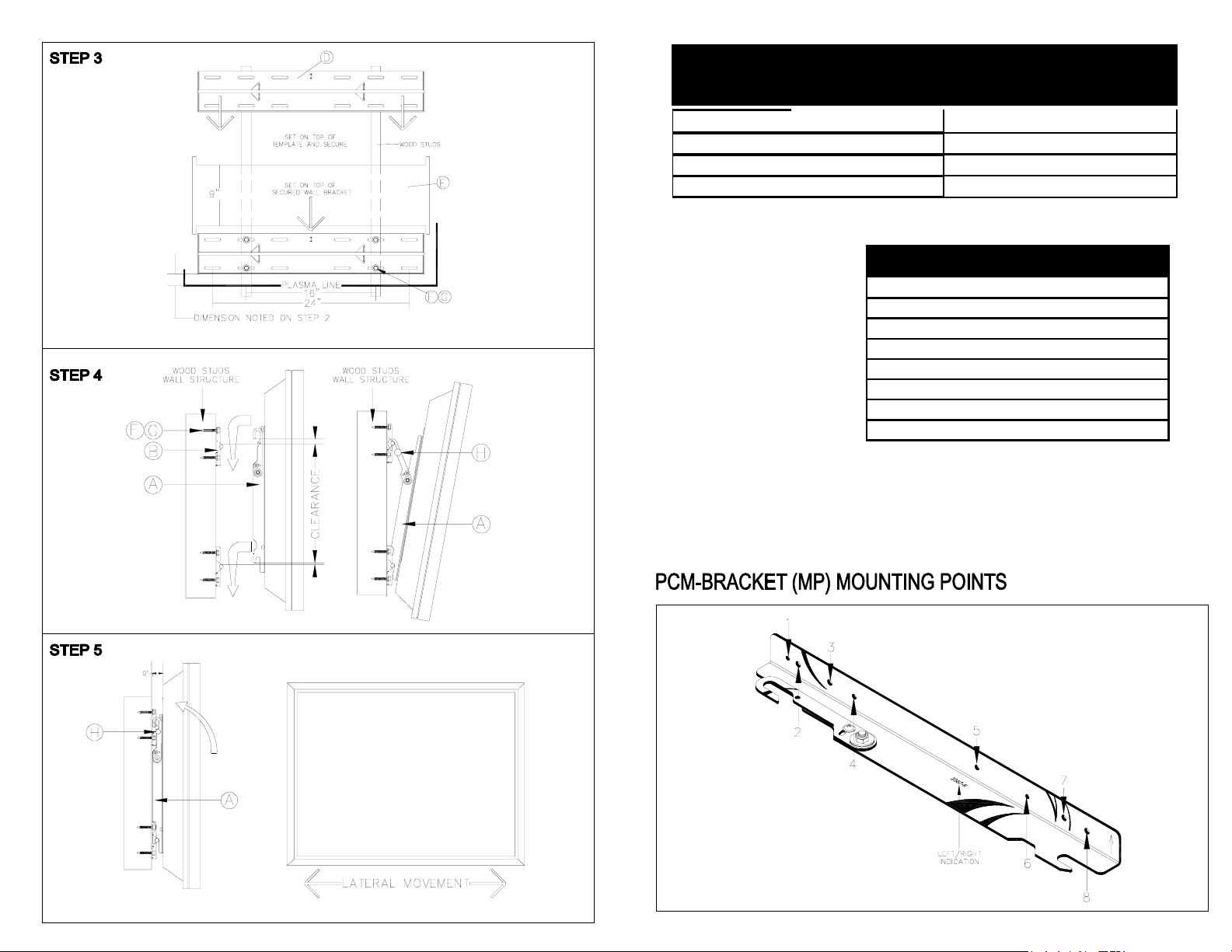
BRAND MODEL # MP HARDWARE
Sony PFM 32C1 3,7
Sony PFM 42B1 1, 8 (4) 6 ( mm) x 12 (mm) (4) 5/ 16 Flat washer spacer s
Sony KZ-32 4,5
Sony KZ-42 2,6 (4) 4 (mm) x 30 (mm) (8) M5 Nylon spacer s 2 per screw
-
(4) 5 ( mm) X 20 (mm) (4) M5 Nylon spacers
(4) 5 ( mm) x 50 (mm) ( 4) 1" Nylon spacer s
#/LR DESCRIPTION QTY
A PCM Mount Brackets L/R
B Hardware See Chart
C SP (Spacers) See Chart
D Wall Brackets 2
E Templete 1
F 5/16" Lag Bolts 8
G 5/16" Flat Washers 8
H 6 mm x 12 mm Securing Knobs 2
Page 3

The wall or ceiling should be capable of supporting a weight of 160 Lbs at least four (4) times the weight of the plasma display. More than 160 Lbs, the ceiling must be reinforced.
 Loading...