

Page 1

Wireless LAN
Access Point
PCWA-A320
Quick Start Guide
Kurzeinführung
Manuel de mise en route
www.vaio-link.com
Page 2

CONTENTS
English -
Quick Start Guide . . . . . . . . . . . . . . . . .page 3
Deutsch -
Kurzeinführung . . . . . . . . . . . . . . . . . .Seite 23
Français -
Manuel de mise en route. . . . . . . . . . .page 45
Page 3

Page 4

Quick Start Guide
3
Page 5

Trademarks
● Sony, VAIO, the logo, the logo and the Eco Info
logo are trademarks of Sony Corporation.
● Microsoft and Windows are registered trademarks of Microsoft
Corporation in the United States and/or other countries.
● In this manual, Microsoft
Windows
● Netscape is a registered trademark of Netscape Communications
®
XP Professional are referred to as Windows XP.
®
Windows® XP Home Edition and Microsoft®
Corporation.
● All other names of systems, products and services are trademarks of their
respective owners. In this manual the
TM
or ® marks are not specified.
™
4
Page 6
Introduction
This document provides an overview of the Wireless LAN Access Point
PCWA-A320 features and the necessary configuration steps.
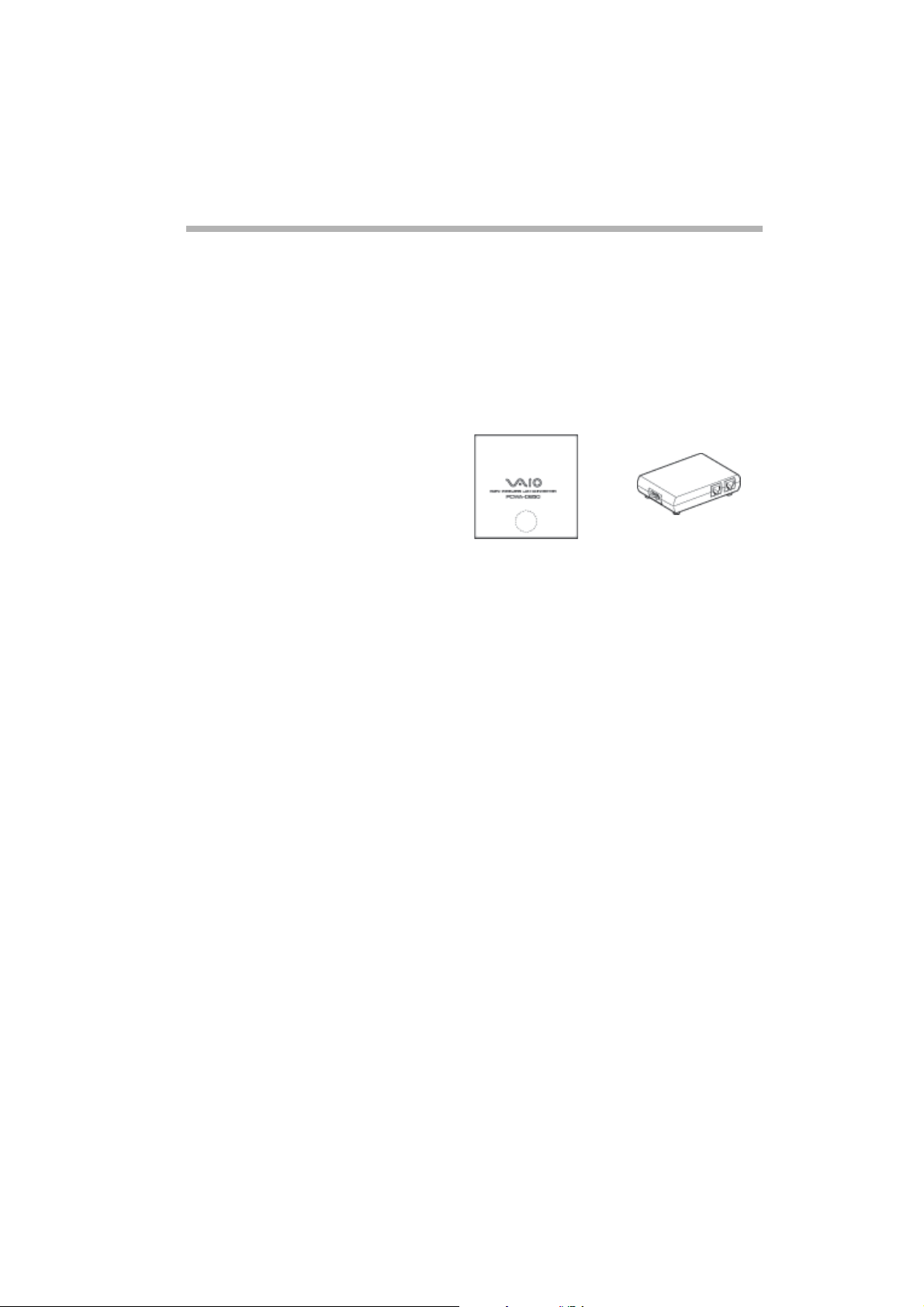
Unpacking your Access Point
Once you have unpacked the unit, make sure that all of the following items
are present:
● Wireless Unit
● Power cord (2x)
● CD-ROM
(setup disc)
● Quick Start Guide
● Troubleshooting Guide
● Warranty leaflet
● Regulatory Leaflet
● Power Unit
5
Page 7
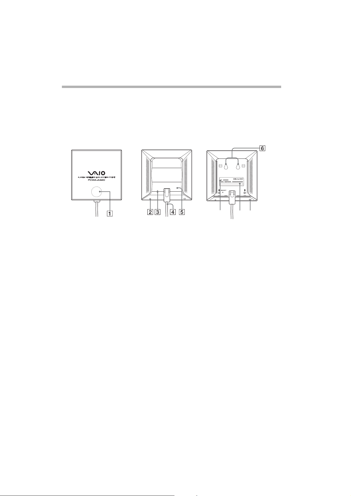
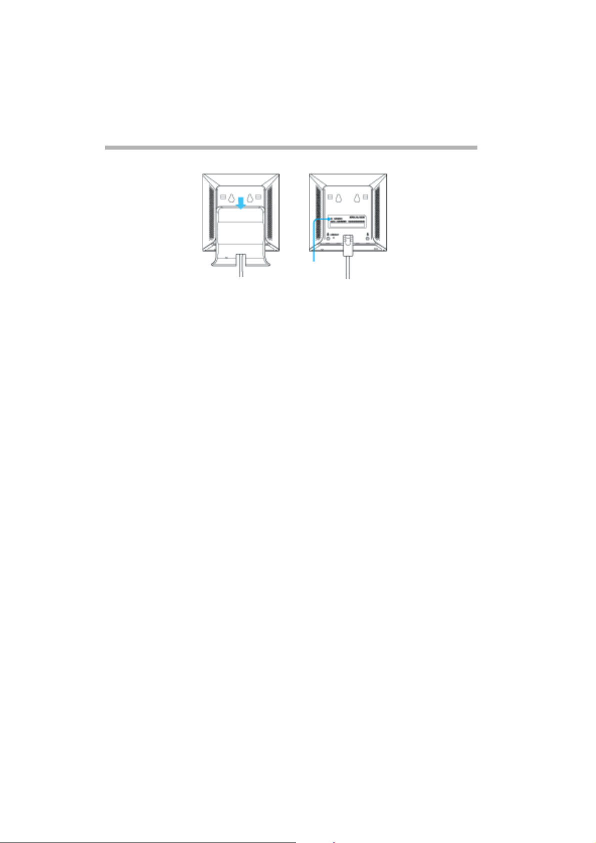
Names of parts and functions
Wireless Unit
Front Rear (With rear cover removed)
7
1 STATUS indicator Indicates the status of the Wireless Unit.
Booting: quickly flashes white.
Normal : slowly flashes white
During firmware update : flashes red
During Quick Setup : flashes red
If firmware update fails : continues flashing red after firmware
update (from this state, you must update the firmware again).
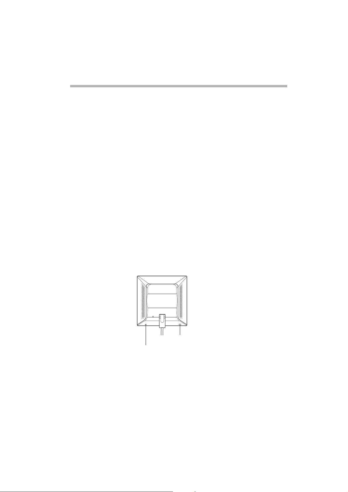
2 Reset switch Returns the Wireless Unit settings to their factory defaults.
3 LINK/ACT indicator Lights when an Ethernet cable is connected to the NETWORK
connector on the Power Unit.
4 Wireless unit cable Connects to the WIRELESS UNIT connector on the Power Unit.
5 Rear cover Remove this cover if you want to hang the Wireless Unit to a wall
and to verify the MAC address and Network Name (SSID).
6 Wall mounting holes Use these holes to hang the Wireless Unit to the wall.
7 ID The six-characte r he xadecimal unique product ID is pr inted here.
This ID is used as the default Network Name (SSID) of the Wireless
Unit.
8 MAC address The Wireless Unit MAC address is printed here.
9 Quick Setup switch Use this switch to set up the Wireless LAN Converter PCWA-DE30.
Refer to the Quick Start Guide of the Wireless LAN Converter or
Help for details.
89
6
Page 8

Power Unit
10 100-240 V AC jack Connect the supplied power cord here.
11 WIRELESS UNIT
connector
12 NETWORK connector Connect the Wirel ess Uni t to you r compute r or oth er dev ice usi ng
Connect the Wireless Unit cable here.
an Ethernet cable.
Use a straight-through or crossover Ethernet cable.
Factory default settings
The factory default settings of the Access Point are:
NAME DEFAULT SETTING
Network Name (SSID) The six characters printed on the label under
Encryption (WEP) Disabled
Frequency (Channel) Auto Select
Broadcast Network Name (SSID) Yes
Access Control Accep t all
Connection Method Obtain an IP address automatica lly (DHCP)
DNS server Speed Auto-Detect
Quick Setup Switch Enable
Time Server (NTP Server) -
the rear cover of the Access Point
(Wireless Unit)
7
Page 9
To reset to the Access Point factory default settings, proceed as follows:
1 Turn on the unit.
2 Press and hold the Reset switch on the bottom of the Wireless Unit for
at least a second with a paper clip.
Be careful not to press the Quick Setup switch by mistake w hen you re set
the Wireless Unit.
3 When the status indicator flashes, release the Reset switch.
The Wireless Unit restarts automatically with all settings returned
to its factory defaults.
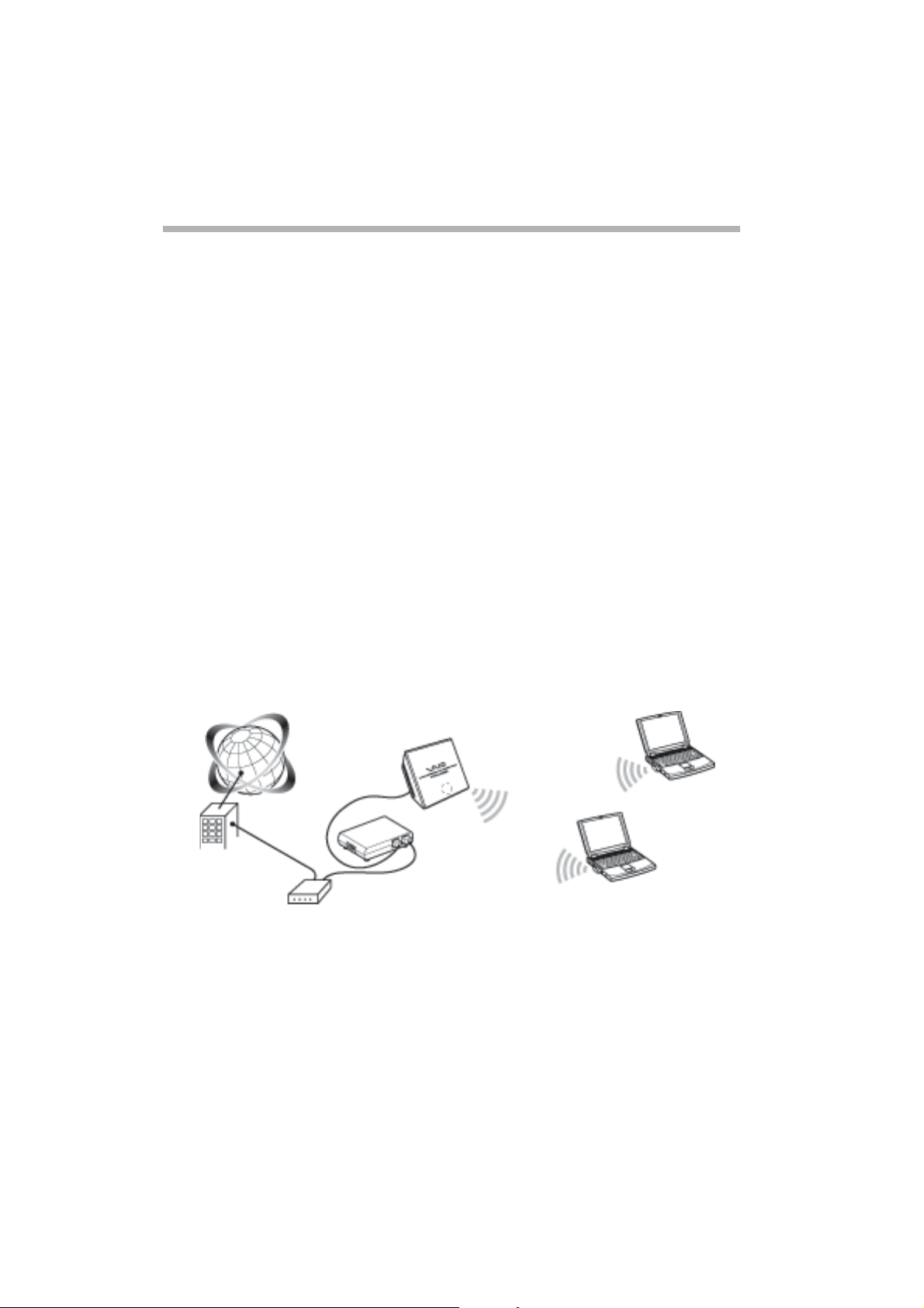
Capabilities
Wireless access to the Internet from a variety of locations
The Wireless LAN Access Point PCWA-A320 (hereafter referred to as Access
Point) is an IEEE 802.11g compliant bridge-type 2.4 GHz wireless LAN access
point. You can use the Access Point as a base station to build a wireless LAN
system consisting of computers equipped with Wireless LAN PC Cards or
Wireless LAN Converters.
If you want to enable the computers that are connected to the wireless LAN
to access the Internet, simply connect the Access Point to a DSL modem, cable
modem, ISDN router, broadband router or another similar communication
device, or to an Ethernet LAN (wired LAN) that is connected to the Internet.
● Use an Ethernet cable to connect the Access Point to the communication device. You
cannot use a USB connection to connect the Access Point to a communication device.
Connect the Access Point to a communicat ion dev ice w ith a rout er function. If the
communication device does no t ha ve a r out er fun ct ion (such as a cable modem),
a separat e br oadband router is required.
8
Page 10

Installation, connectio n an d setu p procedures
1 Perform the necessary preparations and confirmations for connection.
2 Connect the Access Point.
3 Establish a communication session between the computer and
the Access Point.
4 Install the Utility Software.
5 Configure the Access Point settings.
6 Configure the computer settings.
7 Install the Access Point.
Procedure 1 - Preparing and confirming the connections
The procedure in this guide describes the connection process using the factory
default settings.
The factory default settings of the Access Point function are:
● Network Name (SSID) : the 6-character identifier printed on the label inside
the rear cover of the Wireless Unit.
● Encryption (WEP) : disabled.
Before setting up the Access Point, do the following:
1 Set up the Wireless LAN PC Card or Wireless LAN Converter.
Perform the required software installation and settings according to
the instructions provided with your Wireless LAN PC Card or Wireless
LAN Converter to make it operational. Refer to the manuals provided
with your Wireless LAN PC Card or Wireless LAN Converter.
2 Prepare a communication device that can function as a router
(such as a broadband router or an ADSL modem router).
3 Configure the computer firewall settings.
If you are using the Windows XP Internet Connection Firewall or another
personal firewall, you may need to change the security level setting.
Carefully read the Computer Firewall Functions section in this manual.
Computer Firewall Functions
When using the Windows XP Internet Connection Firewall function:
enabling the Windows XP Internet Connection Firewall function may prevent
the computer from being accessed externally (this function is disabled by
default). This function can prevent connection to your network when you
change your Access Point settings. If this happens, disable the Internet
Connection Firewall function, connect to the network and then re-enable
the function. Refer to the Windows XP Help for details.
9
Page 11

● Make sure that you take appr opr iate secur ity m ea su res w hen the Internet Connection
Firewall function is disabled.
When using personal firewall software provided standalone or as part of antivirus or network security software:
antivirus scanning and network security software sometimes includes a
function called a personal firewall intended to prevent unauthorised
access by other computers. Depending on the software, the security level
of this function may initially be set to a high level. If this high security
level setting is left enabled, other computers may be unable to access your
computer. This can cause problems such as not being able to connect to
the network when changing the Wireless Broadband Router settings. In
this event, lower the security level to allow the network connection. While
the security level is lowered, pay special attention to security. It is highly
recommended that you return to the original settings after setting up the
Wireless Broadband Router.
● Pay special attention to security issues.
For questions about firewall functions, please contact your firewall
software manufacturer.
For more details about the Access Point settings, consult the Help files.
To display Help:
Click Start, point to Programs (All Programs in Windows XP),
Wireless LAN and click Access Point Scan Help.
To display Help for the Access Point Setup Page:
Click Help on the Access Point Setup Page.
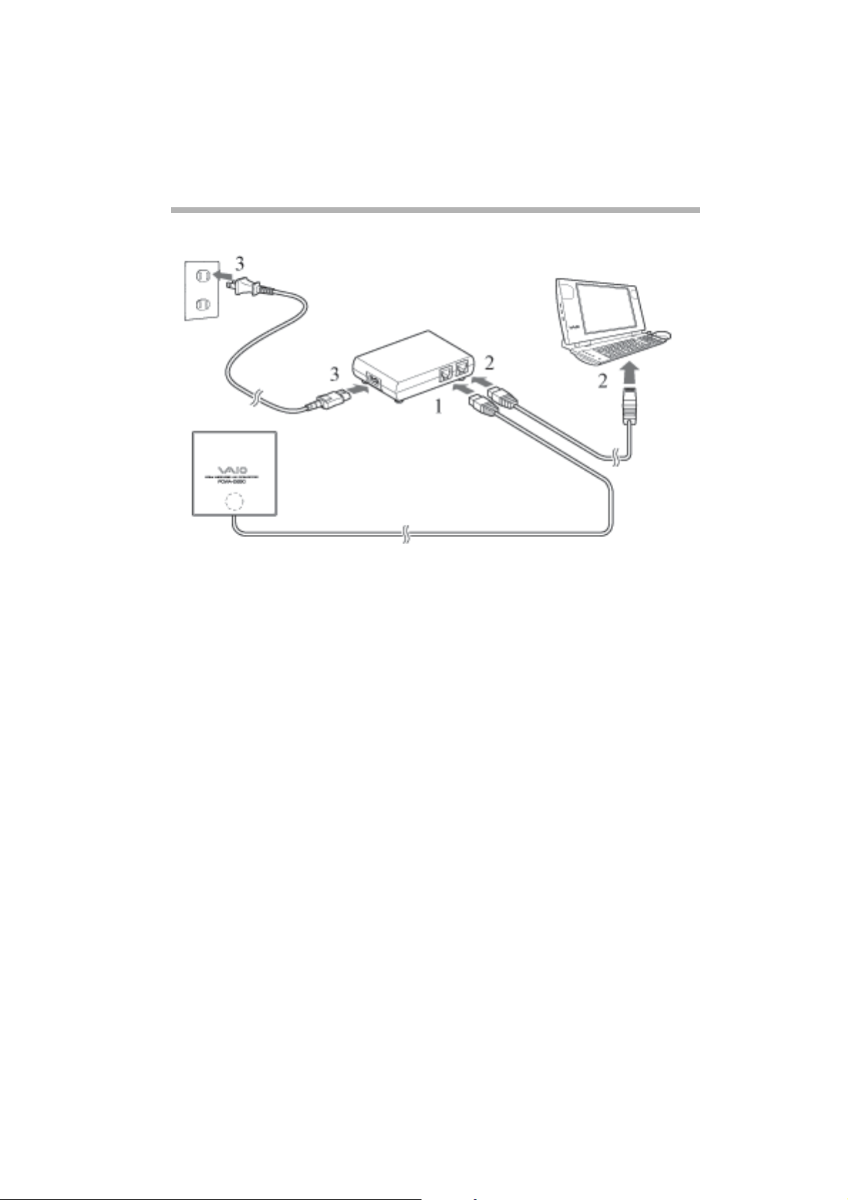
Procedure 2 - Connecting the Access Point
Connect the DSL modem, ISDN router, broadband router or Ethernet LAN.
1 Connect the Wireless Unit and Power Unit.
2 Connect your DSL modem, ISDN router , broadband r outer or Ethernet LAN
hub to the power unit with an Ethernet cable.
3 Connect to the power outlet.
10
Page 12
● The Access Point does not have a power swit ch.
You can use either a straight-through or cross-over Ethernet cable.
● Depending on your provider, you may need to make settings on your computer
and with various connection tools. If this is the case, go to Procedure 3 after making
the required settings.
Connect the Access Point to a communication device with a router function. If the
communication device does not have a router function (such as a cable modem),
a separate broad band router is required.
Establishing a wireless connection
Procedure 3 - Establishing a communication session between
the computer and the Access Point
The procedure in this guide describes the connection process using the factory
default settings.
The factory default settings of the Access Point function are:
● Network Name (SSID) : the 6-character identifier printed on the label inside
the rear cover of the Wireless Unit.
● Encryption (WEP) : disabled.
11
Page 13
Network Name (SSID)
Remove the rear cover
by sliding it in th e
direction of the arrow.
This ID is used a s
the default Network
Name (SSID).
Configure the wireless communication settings on the computer and then
establish a communication session between the computer and your Access
Point. Refer to the manuals provided with your Wireless LAN PC Card or
Wireless LAN Converter for the configuration procedure.
When you are done, check that an IP address is assigned to the computer.
Although communication is possible from this state, for security reasons,
be certain to perform the subsequent procedures to change the factory
default settings.
● The Network Name (SSID) may also be called ESSID or Network ID, depending on
the p articular devi ce.
Encryption may also be called encoding or security depending on the particular device.
When using the Windows XP operating system with a Wireless LAN PC Card, on the Start
menu, click Connect to, Wireless Network Connection and make the communication
settings that affect the con necti on to t he Acce ss Po int from t he d ialo g box tha t ap pears.
If no Wireless Network Co nnection item can be found on the Start menu, click
Control Panel, Network and Internet Connections, Network Connection and
double-click Wireless N et work Connection.
Access Point Settings
Procedure 4 - Installing the Utility Software
Install the Access Point Scan Utility to be able to detect the Access Point on
the computer.
1 Insert the supplied CD-ROM into the computer to which the
Wireless LAN Card or Wireless LAN Converter is connected.
2 For computers running Windows Me or Windows 2000, double-click
the My Computer icon on the desktop.
For computers running Windows XP, click Start and select My Computer.
12
Page 14

3 In My Computer, click the CD-ROM drive icon and then double-click
setup.exe.
The installation program starts. Follow the on-screen instructions
and install the utility software.
● Depending on your computer’s settings, the file name Setup.exe may be
displayed as Setup.
Procedure 5 - Configuring the Access Point settings
Display the Access Point Setup Page and set up the Access Point.
The following browsers are compatible:
● Internet Explorer 5.5 or later;
● Netscape 6.1 or later.
● To display the Wireless LAN Access Point Setup Page from the PCWA-A320 Access Point
software, set one of the Web browsers above as your comput er’s default Web browser.
If your Web browser is configured to use a proxy server, set the browser proxy settings
so the browser does not use a proxy server for the IP address of the Access Point. For
details on how to disable the proxy settings, consult your Troubleshooting Guide - Case 3.
● The Wireless LAN Access Point Setup Page is saved in the internal memory of the
Access Point.
Proceed as follows to configure the Access Point settings:
1 Click the Start button, point to Programs (All Programs in
Windows XP), Wireless LAN and click Access Point Scan.
The Scan Utility starts up, and automatically searches for Access Points
on the same network. Once the Scan Utility finishes searching for
Access Points, it displays a list of Access Points.
If the Scan Utility does not find any Access Points, move the computer to
a location that provides good conditions for wireless communication with
the Access Point and click Scan to search again. For details, refer to the
Troubleshooting Guide - Case 1.
2 Select the Access Point to which you want to connect from the list of
Access Points that were found by the Scan Utility.
If multiple Access Points are shown in the list, check the MAC addresses.
Each Access Point’s MAC address is printed on a bar code label inside the
rear cover of the Wireless Unit. After checking the MAC address, make
sure to reconnect the Ethernet cable.
13
Page 15

3 Click Access Point Setup Page.
The Access Point Setup Page appears.
If the Access Point Setup Page does not appear, check whether a
proxy server is specified in the Web browser settings. If a proxy server
is specified, the Access Point Setup Page cannot be displayed. Set the
browser’ s proxy settings so that the IP address of the Access Point bypasses
the proxy server. Refer to your Troubleshooting Guide - Case 3 or refer
to the Access Point Setup Utility Help for details about bypassing the
proxy server.
4 Click Easy Setup.
The Easy Setup window appears.
5 Enter the network name (SSID).
The network name (SSID) is an ID that serves to identify the wireless
network. Enter up to 32 letters, numbers or symbols.
It is recommended that you write down the network name for
future reference.
6 Set Encryption (WEP) to Enable.
Encryption (WEP) encodes wireless communication sessions and prevents
unauthorised access to the network.
7 Select Key Length.
The encryption key is the password required for WEP communications on
the encrypted network.
8 If you select 40-bit for the Key Length, enter the encryption key and re-
enter it again at WEP Key (confirmation).
Enter up to five letters, numbers and symbols. If you select 104-bit
(WEP 128-bit) for the Key Length, enter up to 13 letters, numbers
and symbols.
It is recommended that you write down the encryption key for
future reference.
9 Click Next.
The setup confirmation window appears.
10 Click the Execute Setup button if you are satisfied with the
displayed settings.
Click the Back button to modify the settings. You will then return to
the previous page.
11 If you are satisfied with the displayed settings, close the Web browser.
● While changing the wireless settings, the conne ct ion to the Ac ce ss Point is disabled.
After completing Pr oc edur e 5, re ad Procedure 6 and reestablish the connection.
14
Page 16
Procedure 6 - Configuring computer settings
Configure the Network Name (SSID) and Encryption (WEP) wireless
communication settings on the computer to match those set on the
Access Point in Procedure 5. After making the settings of your computer,
communication with the Access Point will be enabled.
Refer to the instructions of your Wireless LAN PC Card or Wireless
LAN Converter.
Installing the Access Point
Procedure 7 - Installing the Access Point
When configuration is finished, install the Access Point. Its settings are stored
so that even when it is turned off, the settings are preserved. The Wireless
Unit can be hung to walls.
The settings are now complete.
Resetting the Access Point to factory defaults
1 Turn on the Access Point.
2 With a paper clip or similar object, press and hold the Reset switch
at the bottom of the Wireless Unit for at least one second.
When you press the Reset switch, the indicator on the front of the
Wireless Unit lights red and it starts flashing when the switch is pressed
for one second.
Quick Setup swich
Reset switch
3 When the status indicator starts flashing red, release the Reset switch.
The Access Point restarts under the default settings.
15
Page 17

Obtaining the latest Access Point Firmware
1 Go to http://www.vaio-link.com
2 Check the Wireless LAN Access Point PCWA-A320 page.
It is recommended that you regularly check for firmware updates.
This description assumes that the connection is established with the factory
default settings.
Here are some other things you can do:
● Set an administrator password and gue st password;
● Set the Access Point date and time;
● Set the IP address manually.
For details, see the online Help of the Access Point Setup page.
16
Page 18

Sony’s support options
This section describes how to get help and support from Sony.
● Quick Start Guide (this manual) : explains how to install the Access Point.
● Troubleshooting Guide : provides solutions to the most common problems
users have with their Ac cess Point.
● Online Help for the Access Point Setup Page : explains how to configure
the Access Point.
● Sony’ s support website : http://www.vaio-link.com/ provides the latest
information on your Access Point.
17
Page 19
Installation precautions
Installation
Select a secure location for the Wireless Unit where it cannot drop or fall over.
Route the cable to the Wireless Unit to suit the installation location.
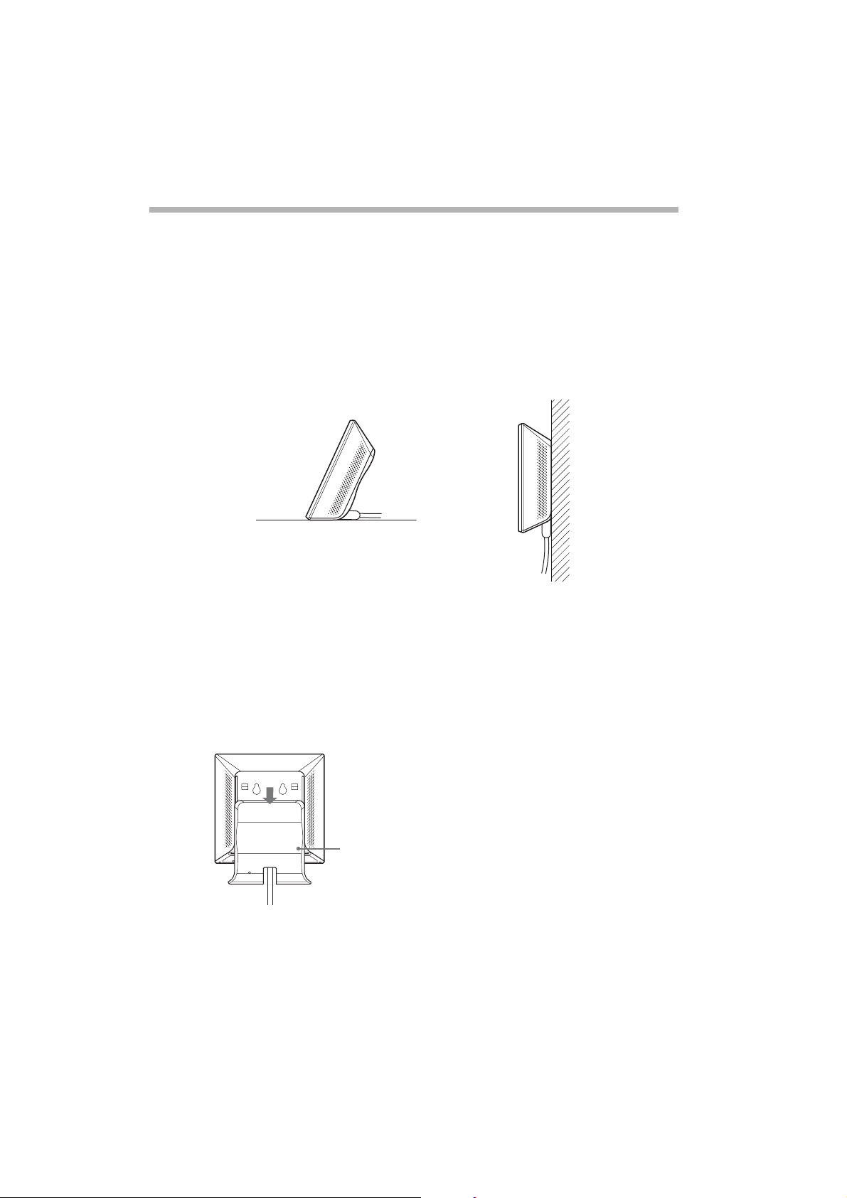
Installation examples
• Desktop installation • Hanging
● Do not install in an insecure location.
Do not install in a location where the Wireless Unit could fall as a result of shock or
vibration, such as on the edge of a shelf.
Do not install in a location where the Wireless Unit or the cables could be accidentally
bumped by a person or other objects .
Hanging the units
1 Locate the wall mounting holes.
To hang the Wireless Unit to a wall, remove the rear
cover by sliding it in the direction of the arrow.
18
Page 20
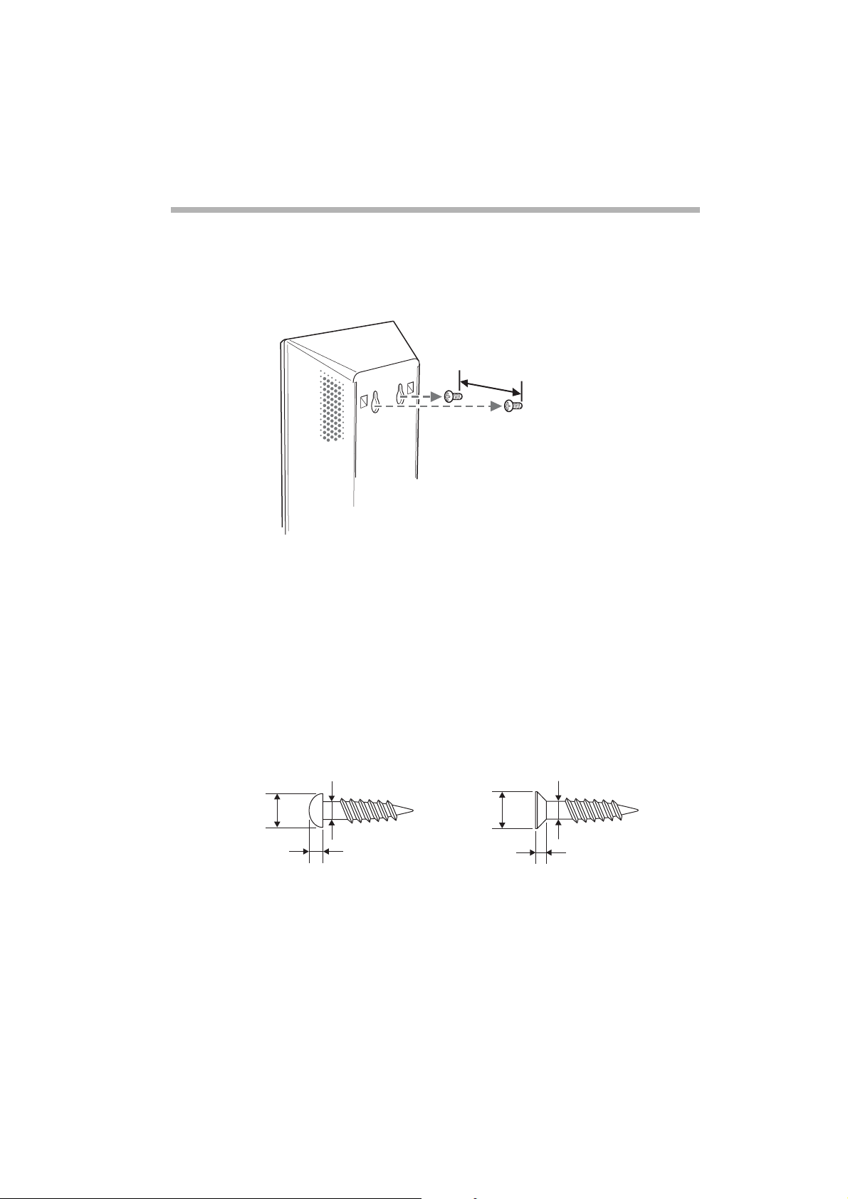
2 Hang the unit to a wall by using screws or nails.
The wireless Unit does not come with any sort of fittings used
to hang it. Use screws of sufficient strenght to support it.
24
units: mm
● Always use two screws or nails and make sure that the unit is secure on the wall.
Select a location that will hold the weight of the unit when hanging it to a wall. If t h e
location cannot hold the weight of the unit, it may fall and cause accide nt s.
When hanging the unit to walls made of plasterboard or other brittle m ater ial, mak e
sure that the material is strong enough to support the unit’s weight and use special screw
fasteners or other fixtures designed for use with that material. If the unit is hung with
ordinary screws, it may fall.
When hanging the unit to a wall, be carefull not to drop the unit or the tools used for
doing the work. Dropping the unit or tools could result in unforeseen accidents.
Recommended screws
Roundhead screws • Flathead screws
Ø5.7
Ø6.2
Ø3.1
2.3
units: mm
Ø3.1
1.8
19
Page 21

Precautions
For regulatory issues or precautions for a safe use, please check
the Wireless LAN Regulations Guide.
Power Unit
Use the Power Unit and the power cord supplied with the Access Point.
Using a different power unit may result in damage and/or injury.
Safety
Do not drop the Access Point. Careful handling helps to prevent damage.
Installation
Do not place the Access Point where it is exposed to the following conditions:
● Unstable surfaces;
● High humidity or poor ventilation;
● Excessive dust;
● Direct sunlight or extreme heat;
● Closed cars;
● Magnetic fields (near magnets, speakers or televisions);
● Frequent vibration;
● Locations where the transmission of radio waves may be obstructed by
metal plates or concrete walls.
Operation
Exposure to rapid changes in temperature or very damp environments can
cause condensation on internal parts. This may prevent the Access Point from
operating properly.
If this should happen, unplug the power cord from the power outlet and
allow the Access Point to dry for two or three hours.
Cleaning
Clean the casing with a soft cloth lightly moistened with water or a mild
detergent solution. Do not use any type of abrasive pad, scouring powder or
solvent such as alcohol or benzene. This may damage the finish of the casing.
Emergencies
In case of an emergency, stop the wireless functions by unplugging the
power cord.
20
Page 22

Specifications
Power AC100 - 240V, 50/60 Hz
Power consumption Approx. 5 W
Interfaces 100BASE-TX/10BASE-T (automatic MDI/MDI-X detection)
Maximum external dimensions Approx. 98x98x33 mm (WxHxD)
Weight Approx. 320 g (inc. connection cable)
Recommended number of
connecte d clients
Protocol support TCP/IP
Standards IEEE 802.11b
Radio frequency 2.4 GHz wireless network: 2.4 to 2.4835 GHz (ISM band)
Maximum connection distance Line of sight approx. 100 m (the maximum connection
WEP (data encryption) 64 bits/128 bits
Modulation methods DS-SS
Operating temperature 5° C to 35° C (no condensation)
Storage temperature -20° C to 60° C (no condensation)
16 or less
IEEE 802.11g
distance depends on t he en vironment)
OFDM
21
Page 23

22
Page 24

Kurzeinführung
23
Page 25

Marken
● Sony, VAIO, das -Logo, das -Logo und das
Eco Info-Logo sind Marken der Sony Corporation.
● Microsoft und Windows sind eingetragene Marken der Microsoft
Corporation in den USA und/oder in anderen Ländern.
● In diesem Handbuch werden Microsoft
und Microsoft
● Netscape ist eine eingetragene Marke der Netscape Communications
®
Windows® XP Professional als Windows XP bezeichnet.
®
Windows® XP Home Edition
Corporation.
● Alle anderen System-, Produkt- und Dienstleistungsnamen sind Marken
ihrer jeweiligen Inhaber. Auf die Zeichen
™
und ® wird in diesem Handbuch
verzichtet.
™
24
Page 26

Einführung
Dieses Dokument bietet einen Überblick über den Wireless LAN Access Point
PCWA-A320-Funktionen und die notwendigen Konfigurationsschritte.
Auspacken des Access Points
Prüfen Sie nach dem Auspacken, das alle folgenden Objekte vorhanden sind:
● Wireless-Einheit
● Netzanschlusskabel (2 x)
● CD-ROM
(Installations-CD-ROM)
● Kurzeinführung
● Handbuch zur Fehlerbehebung
● Garantieerklärung
● Sicherheitsstandards
● Netzeinheit
25
Page 27

Bezeichnungen und Funktionen der Teile
Wireless-Einheit
Vorderseite Rückseite (ohne Rückseiten-
abdeckung)
1 Kontrollleuchte Zeigt den Status der Wireless-Einheit an.
2 Schalter zum
Zurücksetzen
3 LINK/ACT-Leuchte Leuchtet auf, wenn das Ethernetkabel am NETZWERK-Anschluss
4 Kabel der Wireless-
Einheit
5 Abdeckung der Rüc kseite Entfernen Sie die Abdeckung, um die Wireless-Einhei t an
6 Montagelöcher zur
Befestigung an der Wand
7 ID Hier ist die eindeutige Produkt-ID aufgedruckt. Sie besteht
8 MAC-Adresse Hier ist die MAC-Adresse der Wireless-Einheit aufgedruckt.
9 Schalter für
Schnellkonfiguration
Neustart: blinkt in kurz e n Ze it a bs tänden weiß.
Normal: blinkt in längeren Zeitabständen weiß.
Während des Firmware-Updates: blinkt rot.
Während der Schnellkonfiguration: blinkt rot.
Bei Fehlschlagen des Firmware-Updates: blinkt weiterhin rot
nach Firmware-Update (in diesem Fall müssen Sie die Firmware
erneut aktualisieren).
Setzt die Einstellungen der Wireless-Einheit auf die werkseitigen
Standardeinstellungen zurück.
der Netzeinheit angeschlossen ist.
Verbindungskabel für den Anschluss für die WIRELESS-EINHEIT
an der Netzeinheit.
die Wand zu hängen sowie um die MAC-Adresse und den
Netzwerknamen (SSID) zu pr ü f e n .
Verwenden Sie diese Löcher , u m die Wireless-Einheit an der Wand
zu befestigen.
aus einem sechsstelligen Hexadezimalwert. Diese ID wird als
Standardnetzwerkname (SSID) der Wireless-Einheit verwendet.
Verwenden Sie diesen Schalter, um den Wireless LAN Converter
PCWA-DE30 einzurichten. Weitere Einzelheiten und finden Sie in
der Kurzeinführung oder der Hilfe zu Wireless LAN Converter.
26
Page 28

Netzeinheit
10 100-240 V
Anschlussbuchse für
Wechselstrom
11 Anschluss für
WIRELESS-EINHEIT
12 NETZWERK-Anschluss Schließen Sie die Wireless-Einheit mit einem Ethernet-Kabel
Schließen Sie das mitgelieferte Netzanschlusskabel hier an.
Schließen Sie hier das Kabel für die Wireless-Einheit an.
an Ihren Computer oder an ein anderes Gerä t an .
Verwenden Sie ein durchgängiges oder ein EthernetÜbergangskabel.
27
Page 29

Werkseitige Standardeinstellungen
Die Standardeinstellungen für den Access Point lauten:
NAME STANDARDEINSTELLUNGEN
Netzwerkname (SSID) Entspricht den 6 Zeichen auf dem Schild
am Rückgehäuse des Access Points
(Wireless-Einheit)
Verschlüsselung (WEP) Deaktiviert
Frequenz (Kanal) Automatisch auswählen
Netzwerkname übermitteln (SSID) Ja
Zugriffskontrolle Alle akzeptieren
Verbindungsmethode IP-Adresse automatisch beziehen (DHCP)
DNS-Server –
Geschwindigkeit Automatisch erkennen
Schalter für Schnellkonfiguration Aktivieren
Zeitserver (NTP-Server) –
Um einen Access Point auf die werksseitigen Standardeinstellungen
zurückzusetzen , gehen Sie wie fo lgt vo r:
1 Schalten Sie die Einheit ein.
2 Halten Sie den Reset-Schalter unten an der Wireless-Einheit
für mindestens eine Sekunde mit einer Büroklammer gedrückt.
Achten Sie darauf, dass Sie beim Zurücksetzen der Wireless-Einheit
nicht aus Versehen den Schalter für die Schellkonfiguration drücken.
3 Wenn die Statusanzeige blinkt, lassen Sie den Reset-Schalter los.
Die Wireless-Einheit wird automatisch mit allen werkseitigen
Standardeinstellungen neu gestartet.
Funktionen
Drahtloser Zugang zum Internet von verschiedenen Standorten
Der Wireless LAN Access Point PCWA-A320 (nachfolgend Access Point
genannt) ist ein IEEE 802.11g-kompatibler brückenartiger 2,4 GHz Wireless
LAN Access Point. Sie können den Access Point als Basisstation verwenden,
um ein Wireless LAN-System aus Computern aufzubauen, die mit Wireless
LAN PC Cards oder Wireless LAN Converters ausgerüstet sind.
28
Page 30

Wenn Sie für die Computers, die an das Wireless LAN-System angeschlossen
sind, den Zugang zum Internet aktivieren möchten, schließen Sie einfach den
Access Point an das DSL-Modem, Kabelmodem, den ISDN-Router, den
Breitband-Router bzw. ein ähnliches Kommunikationsgerät oder an ein
Ethernet LAN-Adapter (drahtgebundenes LAN) an, das jeweils mit dem
Internet verbunden ist.
● Verwenden Sie ein Ethernet-Kabel, um den Access Point mit dem Kommunikationsgerät
zu verbinden. Sie können den Access Point nicht über einen USB-Anschluss an
ein Kommunikationsgerät anschließen. Verbinden Sie den Access Point mit einem
Kommunikationsge rät mit Router-Funktion . Wenn das Kommunikatio nsgerät nicht über
eine Router-Funktion verfügt, wie z.B. ein Kabelmodem, ist ein separater BreitbandRouter erforderlich.
Installation, Anschluss und Setup
1 Führen Sie die notwendigen Vorgänge zum Vorbereiten und Bestätigen
der Verbindung durch.
2 Schließen Sie den Access Point an.
3 Stellen Sie eine Kommunikationsverbindung zwischen dem Computer
und dem Access Point her.
4 Installieren Sie die Dienstsoftware.
5 Konfigurieren Sie die Access Point-Einstellungen.
6 Konfigurieren Sie die Computer-Einstellungen.
7 Installieren Sie den Access Point.
29
Page 31

Schritt 1 – Vorbereiten und Bestätigen der Verbindung
Das Verfahren in diesem Handbuch beschreibt den Verbindungsprozess
unter Verwendung der werkseitigen Standardeinstellungen.
Die Standardeinstellungen für den Access Point lauten:
● Netzwerkname (SSID): die 6-stellige Kennung ist auf ein Etikett innen
auf der Abdeckung der Rückseite der Wireless-Einheit gedruckt.
● Verschlüsselung (WEP): deaktiviert.
Gehen Sie vor dem Setup des Access Points wie folgt vor:
1 Legen Sie die Wireless LAN PC Card oder den Wireless LAN Conv erter fe st.
Installieren Sie die notwendige Software und legen Sie die Einstellungen
fest, wie in der Betriebsanleitung Ihrer Wireless LAN PC Card oder Ihres
Wireless LAN Converter angegeben wird. Weitere Informationen finden
Sie in den Handbüchern zu Ihrer Wireless LAN PC Card oder Ihrem Wireless
LAN Converter.
2 Bereiten Sie ein Kommunikationsgerät vor, das als Router dienen kann
(z.B. ein Breitband-Router oder ein ADSL-Modem-Router).
3 Konfigurieren Sie die Firewall-Einstellungen des Computers.
Wenn Sie die Windows XP-Internetverbindungsfirewall oder eine
individuelle Firewall verwenden, müssen Sie möglicherweise die
Einstellungen der Sicherheitsstufe ändern. Lesen Sie gründlich den
Abschnitt zu den Funktionen der Firewall des Computers.
Firewall-Funktionen des Computers
Die Funktion der Internetverbindungsfirewall unter Windows XP:
Die Aktivierung der Windows XP-Internetverbindungsfirewall verhindert
einen möglichen Zugriff von außerhalb auf den Computer (diese Funktion
ist standardmäßig aktiviert). Diese Funktion kann die Netzwerkverbindung
verhindern, wenn Sie den Access Point wechseln. Deaktivieren Sie in diesem
Fall die Funktion für die Internetverbindungsfirewall, stellen Sie eine
Netzwerkverbindung her, und aktivieren Sie dann die Funktion erneut.
Nähere Informationen finden Sie in der Windows XP-Hilfe.
● Stellen Sie sicher, dass Sie die geeigneten Sicherh eitsm aß nahm en ergreifen, wenn die
Internetverbindungsfirewall deaktiviert ist.
30
Page 32

Wenn Sie eine individuelle Firewall-Software verwenden, die separat,
als Teil einer Anti-Virus- oder Sicherheitssoftware bereitgestellt wurde:
Antivirenprogramme oder Software-Anwendungen für die
Netzwerksicherheit enthalten manchmal eine Funktion, die individuelle
Firewall genannt wird, durch die der unerwünschte Zugang von anderen
Computern verhindert wird. Je nach Software ist die Sicherheitsstufe
dieser Funktion ursprünglich sehr hoch eingestellt. Wenn diese hohe
Sicherheitsstufe aktiviert bleibt, ist der Zugriff auf Ihren Computer von
anderen Computern möglicherweise nicht möglich. Dies kann Probleme
verursachen. Sie können möglicherweise keine Netzwerkverbindung
herstellen, wenn Sie die Einstellungen des Wireless Broadband Routers
ändern. Setzen Sie die Sicherheitsstufe in diesem Fall auf ein niedrigeres
Niveau, damit eine Netzwerkverbindung herstellt werden kann. Wenn
die Sicherheitsstufe niedriger eingestellt ist, achten Sie besonders auf die
Sicherheit. Es wird stark empfohlen, dass Sie nach dem Setup des Wireless
Broadband Routers zu den Originaleinstellungen zurückkehren.
● Achten Sie besonders auf die Sicherheitsaspekte.
Wenden Sie sich bei Fragen in Bezug auf die Firewall-Funktionen an Ihren
Firewall-Hersteller.
Weitere Einzelheiten zu den Einstellungen des Access Points finden Sie
in der Online-Hilfe.
So zeigen Sie die Online-Hilfe an:
Klicken Sie auf Start, zeigen Sie auf Programme (Alle Programme in
Windows XP), Wireless LAN und klicken Sie auf A ccess Point Scan-H i lf e.
So zeigen Sie die Hilfe zur Access Point Setup-Seite an:
Klicken Sie auf der Access Point-Setup-Seite auf Hilfe.
31
Page 33

Schritt 2 – Anschließen des Access Points
Schließen Sie das DSL-Modem, den IDSN- oder Breitband-Router oder den
Ethernet LAN-Hub an.
1 Schließen Sie die Wireless-Einheit an die Netzeinheit.
2 Schießen Sie Ihr DSL-Modem, Ihren ISDN- oder Breitband-Router oder
Ethernet LAN-Hub mit einem Ethernetkabel an die Netzeinheit.
3 Schließen Sie die Netzeinheit an die Steckdose an.
● Der Access Point verfügt über keinen Netzschalter.
Sie können entweder ein durchgehendes oder ein Ehternet-Übergangskabel verwenden.
● Je nach Betreiber müssen Sie möglicherweise Einste llungen auf Ihrem Computer und
bei verschiedenen Verbindungstools vornehmen. Wenn das der Fall ist, fahren Sie mit
Schritt 3 fort, nachd em Sie die er fo rd erlich en Eins tellun gen vorgenommen haben.
Verbinden Sie den Access Point mit einem Kommunikations gerät mit Router-Funktion.
Wenn das Kommunikationsgerät nicht ü ber eine Router-Funktion verfügt, wie z.B. ein
Kabelmo d em , ist ein separater Breitb and-Router erforderlich.
32
Page 34

Herstellen einer Funkverbindung
Schritt 3 – Herstellen einer Kommunikationsverbindung
zwischen dem Computer und dem Access Point
Das Verfahren in diesem Handbuch beschreibt den Verbindungsprozess
unter Verwendung der Standardeinstellungen.
Die Standardeinstellungen für den Access Point lauten:
● Netzwerkname (SSID): die 6-stellige Kennung ist auf ein Etikett innen
auf der Abdeckung der Rückseite der Wireless-Einheit gedruckt.
● Verschlüsselung (WEP): deaktiviert.
Netzwerkname
(SSID)
Entfernen Sie die hintere
Abdeckung, indem Sie sie
in Pfeilrichtung bewegen.
Diese ID wird als
Standardnetzwerkname
(SSID) verwendet.
Konfigurieren Sie die Einstellungen für die drahtlose Kommunikation
auf dem Computer und stellen Sie dann eine Kommunikationsverbindung
zwischen dem Computer und dem Access Point her. Weitere Informationen
zur Konfiguration finden Sie in den Handbüchern zu Ihrer Wireless LAN PC
Card oder Ihrem Wireless LAN Converter.
Wenn der Vorgang abgeschlossen ist, prüfen Sie, ob dem Computer die
IP-Adresse zugewiesen wurde.
Auch wenn die Kommunikation in diesem Stadium möglich ist, müssen Sie
aus Sicherheitsgründen die nachfolgenden Schritte unternehmen, um die
werkseitigen Standardeinstellungen zu ändern.
33
Page 35

● Der Netzwerkname (SSID) kann je nach Gerät auch ESSID oder Netzwerk-ID lauten.
Verschlüsselung kann je nach Gerät auch Kodier ung oder Sicherheit genannt werden.
Unter dem Betriebssystem Windows XP mit Wireless LAN PC Card, klicken Sie im
Menü Start auf Verbinden, Drahtlose Netzw er kver bi ndung, und legen Sie im
angezeigten Dialogfenste r die Komm unikationseinstellungen für die Verbindung
zum Access Point fest.
Wenn Drahtlose Netzwerkverbindung nicht im Menü Start ge fu nde n w ird,
klicken S i e auf Systemsteuerung, Netzwerk und Internet verbindungen,
Netzwerkverbindungen, und doppelklicken Sie auf Drahtlose
Netzwerkverbindungen.
Access Point-Einstellungen
Schritt 4 – Installieren der Dienstsoftware
Installieren Sie die Access Point Scan Utility, um den Access Point auf Ihrem
Computer zu erkennen.
1 Legen Sie die mitgelieferte CD-ROM in den Computer ein, mit dem die
Wireless LAN Card oder der Wireless LAN Converter verbunden ist.
2 Auf Computern unter Windows Me oder Windows 2000, doppelklicken
Sie auf das Symbol Arbeitsplatz auf Ihrer Benutzeroberfläche.
Auf Computern unter Windows XP, klicken Sie auf Start, und wählen
Sie Arbeitsplatz.
3 In Arbeitsplatz, klicken Sie auf das Symbol für das CD-ROM-Laufwerk
und doppelklicken Sie auf setup.exe.
Je nach den Einstellungen Ihres Computers, wird der Dateiname
Setup.exe möglicherweise als Setup angezeigt. Wenn mehrere Dateien
mit dem Namen Setup im selben Ordner vorkommen, doppelklicken Sie
auf die Datei mit dem Symbol, das in Schritt 3 angezeigt wird.
Schritt 5 – Konfigurieren der Access Point-Einstellungen
Zeigen Sie die Access Point Setup-Seite an und führen Sie das Setup des
Access Points durch.
Die folgenden Browser sind kompatibel:
● Internet Explorer 5.5 oder höher;
● Netscape 6.1 oder höher.
34
Page 36

● Richten Sie einen der oben aufgefü hr ten Web-Browser als de n St andard-Web-Browser
Ihres Computers ein, um die Wireless LAN Access Point-Setup-Seite von der PCWA-A320
Access Point-Software aus anzuzeigen.
Wenn Ihr Web-Browser für die Nutzung eines Proxy-Servers konfiguriert ist, richten
Sie die Proxy-Einstellungen des Browsers so ein, dass der Browser keinen Proxy-S er ver
für die Access Point IP-Adresse verwendet. Weitere Einzelheiten zur Deakt ivier ung der
Proxy-Einstellungen finden Sie in Ihrem Handbuch zur Fehlerbehebung – Fall 3.
● Die Wireless LAN Access Point-Setup-Seite wird im internen Speicher des Access Points
gespeichert.
So konfigurieren Sie den Access Point:
1 Klicken Sie auf Start, zeigen Sie auf Programme (Alle Programme in
Windows XP), Wireless LAN und klicken Sie auf Access Point Scan.
Die Scan Utility startet und sucht automatisch nach Access Points
im selben Netzwerk. Nachdem Scan Utility die Suche nach Access Points
beendet hat, wird eine Liste von Access Points angezeigt.
Wenn Scan Utility keine Access Points findet, stellen Sie den Computer
an einen Standort um, an dem die Bedingungen für drahtlose
Kommunikation mit dem Access Point besonders günstig sind, und klicken
Sie auf Scannen, um erneut zu suchen. Detaillierte Informationen hierzu
finden Sie im Handbuch zur Fehlerbehebung – Fall 1.
2 Wählen Sie den Access Point, zu dem Sie eine Verbindung herstellen
möchten von der Liste der Access Points, die Scan Utility gefunden hat.
Wenn mehrere Access Points auf der Liste angezeigt werden, prüfen Sie
die MAC-Adressen. Die MAC-Adressen der Access Points sind immer auf
ein Etikett in der Innenseite der Rückwandabdeckung der Wireless-Einheit
gedruckt. Wenn Sie die MAC-Adressen überprüft haben, prüfen Sie, ob
das Ethernet-Kabel angeschlossen ist.
3 Klicken Sie auf Access Point Setup-Seite.
Die Access Point Setup-Seite wird angezeigt.
Wenn die Access Point Setup- Seite nicht angezeigt wird, prüf en Sie,
ob in den Web-Browser-Einstellungen der Proxy-Server eingestellt ist.
Wenn der Proxy-Server angegebe n ist , kann die Access Point Setup-Seite
nicht angezeigt werden. Legen Sie die Browser-Einstellungen so fest,
dass die IP-Adresse des Access Points vom Proxy-Server umgangen wird.
Weitere Informationen zur Umgehung des Proxy-Servers finden Sie in
Ihrem Handbuch zur Fehlerbehebung – Fall 3 oder in der Hilfe zum Access
Point Setupprogramm.
4 Klicken Sie auf Einfaches Setup.
Das Fenster Einfaches Setup wird angezeigt.
35
Page 37

5 Geben Sie den Netzwerknamen (SSID) ein.
Der Netzwerkname (SSID) dient zur Identifizierung des drahtlosen
Netzwerks. Geben Sie bis zu 32 Buchstaben, Zahlen oder Symbole ein.
Es ist empfehlenswert, den Netzwerkname als Referenz für später
aufzuschreiben.
6 Setzen Sie die Versch lüsselung (WEP) auf Aktiviert fest.
Die Verschlüsselung (WEP) kodiert drahtlose Kommunikationsverbindungen und verhindert unbefugten Zugang zum Netzwerk.
7 Wählen Sie Schlüssellänge.
Der Verschlüsselungsschlüssel ist das erforderliche Kennwort für die
WEP-Kommunikation im verschlüsselten Netzwerk.
8 Wenn Sie 40-Bit als Schlüssellänge wählen, geben Sie den
Verschlüsselungsschlüssel ein und geben Sie ihn anschließend erneut
unter WEP-Schlüssel (Bestätigung) ein.
Geben Sie bis zu 5 Buchstaben, Zahlen oder Symbole ein. Wenn Sie
104-Bit (WEP 128-Bit) als Schlüssellänge wählen, geben Sie bis zu
13 Buchstaben, Zahlen und Symbolen ein.
Es ist empfehlenswert, den Verschlüsselungsschlüssel als Referenz für
später aufzuschreiben.
9 Klicken Sie auf Weiter.
Es wird ein Bestätigungsfenster für das Setup eingeblendet.
10 Klicken Sie auf die Schaltfläche Setup ausführen, wenn Sie mit den
angezeigten Einstellungen zufrieden sind.
Klicken Sie auf Zurück, um die Einstellungen zu ändern. Dadurch
gelangen Sie zu der vorherigen Seite.
11 Wenn Sie mit den angezeigten Einstellungen einverstanden sind,
schließen Sie den Web-Browser.
● Während der Änderung der Wireless-Einstellungen, ist die Verbindung zum Access Point
unterbrochen. Nach Beenden von Schritt 5, lesen Sie Schritt 6 und stellen Sie erneut eine
Verbindung her.
Schritt 6 – Konfigurieren der Computereinstellungen
Konfigurieren Sie den Netzwerknamen (SSID) und die Einstellungen für die
Verschlüsselung (WEP) der drahtlosen Kommunikation auf dem Computer,
um sie den Einstellungen des Access Points anzupassen, wie sie in Schritt 5
festgelegt wurden. Nachdem Sie die Einstellungen auf Ihrem Computer
festgelegt haben, ist die Kommunikation mit dem Access Point aktiviert.
Weitere Informationen finden Sie in den Anweisungen zu Ihrer Wireless
LAN PC Card oder Ihrem Wireless LAN Converter.
36
Page 38

Installieren des Access Points
Schritt 7 – Installieren des Access Points
Nach Beenden der Konfiguration installieren Sie den Access Point. Die
Einstellungen sind gespeichert, so dass sie beibehalten werden, wenn
der Access Point abgeschaltet ist. Die Wireless-Einheit kann an die Wand
gehängt werden.
Die Einstellungen sind nun festgelegt.
Zurücksetzen der Access Points auf die werkseitigen
Einstellungen
1 Schalten Sie den Access Point ein.
2 Drücken Sie den Reset-Schalter unten am Wireless LAN Converter mit
einer Büroklammerspitze oder einem ähnlichen Gegenstand mindestens
eine Sekunde lang.
Wenn Sie den Schalter Reset gedrückt halten, leuchtet die Kontrolllampe
an der V orderseite der Wireless-Einheit rot und beginnt zu blinken, wenn
der Schalter eine Sekunde gehalten wurde.
Schalter für
Reset-Schalter
3 Wenn die Statusanzeige rot zu blinken beginnt, lassen Sie den Reset-
Schalter los.
Der Access Point wird unter den werkseitigen Einstellungen erneut
gestartet.
Schnellkonfiguration
37
Page 39

Anfordern der neuesten Access Point Firmware
1 Gehen Sie auf http://www.vaio-link.com
2 Lesen Sie die Seite zu Wireless LAN Access Point PCWA-A320.
Wir empfehlen, die Website regelmäßig auf Fir mware-Updates zu prüfe n.
Diese Beschreibung setzt voraus, dass die Verb indung unter den werkseitigen
Einstellungen hergestellt wird.
Weiterhin können Sie:
● Ein Administrator- und ein Gäste-Kennwort festlegen;
● Das Datum und die Uhrzeit festlegen;
● Manuell eine IP-Adresse zuweisen.
Weitere Informationen finden Sie in der Online-Hilfe zur Access Point
Setup-Seite.
38
Page 40

Sony-Kundendienstoptionen
In diesem Abschnitt wird beschrieben, wie Sie Hilfe und Unterstützung von
Sony erhalten.
● Kurzeinführung (dieses Dokument): Beschreibt die Installierung des
Access Points.
● Handbuch zur Fehlerbehebung: Bietet Lösungen zu am häufigsten
auftretenden Problemen, die Anwender mit Ihren Access Points haben
können.
● Online-Hilfe zur Access Point Setup-Seite: Beschreibt die Konfiguration
des Access Points.
● Sony-Kundendienst-Website: http://www.vaio-link.com/ stellt die neuesten
Informationen zu Ihrem Access Point bereit.
39
Page 41

Vorsichtsmaßnahmen bei der Installation
Installation
Wählen Sie einen sicheren Standort, wo Ihre Wireless-Einheit nicht
herunterfallen oder umkippen kann. Verlegen Sie das Kabel zur WirelessEinheit entsprechend des Installationsstandorts.
Beispiele für die Installation
• Desktop-Installation • Aufhängen
● Installieren Sie nich t an einem unsicheren Standort.
Führen Sie die Installation nicht an einem Standort durch, wo die Wireless-Einheit durch
einen Stoß oder Vibration herunterfallen könnte, wie z.B. vom Rand e ines Re gals .
Führen Sie die Installation nicht an einem St andort durch, wo die Wireless-Einheit oder
die Kabel von einer Person oder einem Objekt aus Versehen beschädigt werden könnten.
Aufhängen von Gerä t e - E inheiten
1 Suchen Sie die Löcher für die Wandbefestigung.
Um die Wireless-Einheit an der Wand zu befestigen,
entfernen Sie die Rückwandabdeckung,
indem Sie die Abdeckung in Pfeilrichtung schieben.
40
Page 42

2 Hängen Sie das Gerät mithilfe von Schrauben oder Nägeln an die Wand.
Im Lieferumfang der Einheit sind keine Haken oder Ähnliches für
die Wandbefestigung enthalten. Verwenden Sie Schrauben, die stabil
genug sind.
24
Einheiten: mm
● Verwenden Sie immer zwei Schrauben oder Nägel und p rüfen Sie, ob die Einheit sicher
an der Wand hängt.
Wählen Sie einen Befestigungsort, wo das Gewich t de s Geräts a n der Wand gehalten
werden kann. Wenn der Befestigungsort das Gewicht des Geräts nicht halten kann,
fällt sie herunter und veru rsac ht Un fälle.
Wenn Sie die Einheit an einer Wand aus Gipskarton oder anderem spröden
Material aufhängen, prüfen Sie, ob das Material stabil genug ist, um das Gewicht
des Geräts zu tragen, und verwenden Sie besondere Schrauben oder andere
Befestigungsvorrichtungen, die speziell für dieses Material geeignet sind. Wenn Sie das
Gerät mit herkömmlichen Schraub en befe stigen, fällt es möglicherwei se heru nter.
Achten Sie darauf, dass bei der Befestigung an der Wand, das Ge rät und die
Befestigungswerkzeuge nicht herunterfallen. Durch das Herunterfallen des Geräts oder
der Werkzeuge kann es zu unvorhergese hen en Unf ällen kommen.
Empfohlene Schrauben
Rundkopfschrauben • Flachkopfschrauben
Ø 5,7
Ø 6,2
Ø 3,1
2,3
Einheiten: mm
Ø 3,1
1,8
41
Page 43

Einschränkungen
Weitere Informationen zu den Sicherheitsstandards und Vorsichtsmaßnahmen zur Gewährleistung einer sicheren Verwendung finden Sie im Wireless
LAN-Leitfaden.
Netzeinheit
Verwenden Sie die Netzeinheit und das Netzanschlusskabel, das im
Lieferumfang des Access Points enthalten ist. Das Verwenden einer anderen
Netzeinheit kann zu Beschädigungen und/oder Verletzungen führen.
Sicherheit
Lassen Sie den Access Point nicht fallen. Handhaben Sie die Hilfsvorrichtungen
vorsichtig, um Beschädigungen zu vermeiden.
Installation
Vermeiden Sie bei der Platzierung des Access Points St andorte mit folgenden
Bedingungen:
● Instabile Oberflächen;
● Hohe Luftfeuchtigkeit oder mangelhafte Belüftung;
● Übermäßig viel Staub;
● Direkte Sonneneinstrahlung oder extrem hohe Temperaturen;
● Geschlossene Fahrzeuge;
● Magnetumfeld (in der Nähe von Magneten, Lautsprechern oder
Fernsehgeräten);
● Häufige Erschütterungen;
● Orte, an denen die Funkwellenübertragung durch Metallplatten oder
Betonwände gehindert werden könnte.
Betrieb
Bei starken Temperaturschwankungen oder sehr feuchten Umgebungen
kann sich im Geräteinneren Kondensation niederschlagen. Der Access Point
funktioniert dann möglicherweise nicht mehr einwandfrei.
In diesem Fall ziehen Sie das Netzkabel aus der Steckdose und lassen Sie den
Access Point während zwei oder drei Stunden trocknen.
42
Page 44

Reinigen
Reinigen Sie das Gehäuse mit einem weichen, mit Wasser oder mit einer
milden Reinigungsmittellösung leicht angefeuchteten Tuch. Verwenden Sie
unter keinen Umständen Scheuerschwämme und Scheuer- oder Lösungsmittel
wie Alkohol oder Benzin. Diese können die Oberfläche der Verkleidung
beschädigen.
Notfälle
Im Falle einer Notsituation, stoppen Sie die drahtlosen F unktionen, indem Sie
das Netzkabel auf der Steckdose ziehen.
43
Page 45

Technisch e Daten
Netzbetrieb AC100 – 240V, 50/60 Hz
Stromverbrauch Ca. 5 W
Schnittstellen 100BASE-TX/10BASE-T
(automatische MDI/MDI-X-Kennung)
Max. äußere Abmessungen Ca. 98 x 98 x 33 mm (B x H x T)
Gewicht Ca. 320 g (inkl. Verbindungskabel)
Empfohlene Anzahl
der angebundenen Clients
Unterstütztes Protokoll TCP/IP
Standards IEEE 802.11b
Funkfrequenz 2,4 GHz Funknetzwerk: 2,4 - 2,4835 GHz (ISM Band)
Max. Anschlussentfernung Reichweite mit direkter Sicht ca. 100 m (die maximale
WEP (Datenverschlüsselung): 64 Bits/128 Bits
Modulationsverfahren DS-SS
Betriebstemperatur 5° C - 35° C (keine Kondensation)
Lagertemperatur -20° C - 60° C (keine Kondensation)
Max. 16
IEEE 802.11g
Anschlussentfernung ist von der Umgebung abhängig)
OFDM
44
Page 46

Manuel de mise en route
45
Page 47

Marques commerciales
● Sony, VAIO, le logo , le logo et le logo
Eco Info sont des marques commerciales de Sony Corporation.
● Microsoft et Windows sont des marques commerciales de Microsoft
Corporation, déposées aux États-Unis et/ou dans d’autres pays.
● Microsoft
®
Windows® XP Édition familiale et Microsoft® Windows®
XP Professionnel sont ci-après nommés Windows XP.
● Netscape est une marque commerciale déposée de Netscape
Communications Corporation.
● Tous les autres noms de systèmes, de produits et de services sont des
marques commerciales de leurs propriétaires respectifs. Les symboles
®
ou
ne sont pas repris dans ce manuel.
™
TM
46
Page 48

Présentation
Ce document donne un aperçu des fonctionnalités du point d’accès
LAN sans fil
PCWA-A320 et explique la procédure de configuration requise.
Déballage du point d’accès
Après avoir déballé l’unité, assurez-vous que tous les éléments ci-aprè s ont été
livrés :
● Unité sans fil
● Cordon d’alimentation (2)
● CD-ROM (disque d’installation)
● Guide de mise en route
● Guide de dépannage
● Dépliant de garantie
● Dépliant de réglementation
● Unité d’alimentation
47
Page 49

Nom et fonction des divers éléments
Unité sans fil
7
1 Indicateur d’ÉTAT Indique l’état de l’unité sans fil.
2 Bouton de
réinitialisation
3 Indicateur de liaison/
d’activité
4 Câble de l’unité sans fil Se branche sur le port UNITÉ SANS FIL de l’unité d’alimentation.
5 Panneau arrière Retirez ce panneau si vous souhaitez fixer l’unité sans fil au mur et
6 Orifices de fixation
murale
7 Identifiant (ID) Le nom d’identification unique du produit, composé de six
8 Adresse MAC L’adresse MAC de l’unité sans fil est impri mée à cet emplacement.
9 Bouton de
configuration rapide
Démarrage : clignotement rapide (blanc).
Normal : clignotement lent (blanc).
Pendant la mise à jour du micrologiciel : clignote m e nt r ouge .
Pendant la configura t ion rapide : clignotement r ouge
Si la mise à jour du micrologiciel échoue : clignotem e nt continu
(rouge) après la mise à jour. (Vous devez alors relancer la mise
à jour du micrologiciel.)
Rétablit les valeurs par défaut des paramètres de l’unité sans fil.
S’allume lorsqu’ un câbl e Ethe rn et es t branc hé au port RÉS EAU de
l’unité d’alimentation.
pour vérifier l’adresse MAC et le nom de réseau (SSID).
Utilisez-le s pour fixer l’unité sans fil a u m ur.
caractères hexadécimaux est imprimé à cet emplacement. Il est
utilisé comme nom de réseau (SSID) par défaut de l’unité sans fil.
Utilisez ce bouton pour conf igurer le convertisse ur LAN sans fil
PCWA-DE30. Reportez-vous au guide de mise en route du
convertisseur LAN sa ns fi l ou à so n ai de e n ligne pour de plus
amples informations.
89
48
Page 50

Unité d’alimentation
10 Prise secteur 100-240 V Branchez le cordon d’alimentation fourni ici.
11 Port UNITÉ SANS FIL Branchez le câble de l’unité sans fil ici.
12 Port RÉSEAU Utilisez le câble Ethernet pour brancher l’unité sans fil
sur l’ordinateur ou un autre périphérique.
Utilisez un câble Ethernet droit ou croisé.
Paramètres par défaut
Les paramètres par défaut du point d’accès sont les suivants :
NOM PARAMÈTRE PAR DÉFAUT
Nom de réseau (SSID) Les six caractères imprimés sur l’étiquette,
sur le panneau arrière du point d’accès
(unité sans fil)
Cryptage (WEP) Désactivé
Fréquence (canal) Sélection automatique
Diffusion du no m de réseau (SSID ) O ui
Contrôle d’accès Accepter tout
Méthode de connexion Obtenir une adresse IP automatiquement
Serveur DNS Vitesse Détection automatique
Bouton de configuration rapide Activé
Serveur de temps (serveur NTP) -
(DHCP)
49
Page 51

Pour rétablir les paramètres par défaut, procédez comme suit :
1 Mettez l’unité sous tension.
2 Appuyez sur le bouton de réinitialisation situé en bas de l’unité sans
fil pendant une seconde au moins avec un trombone.
Veillez à ne pas appuyer par erreur sur le bouton de configuration rapide
lors de la réinitialisation de l’unité sans fil.
3 Lorsque l’indicateur d’état clignote, relâchez le bouton de réinitialisation.
L’unité sans fil redémarre automatiquement avec les paramètres
par défaut.
Fonctionnalités
Accès sans fil à Internet à partir de différents emplacements
Le point d’accès LAN sans fil PCWA-A320 — ci-après dénommé
« point d’accès » — est un point d’accès LAN sans fil 2,4 GHz de type passerelle
compatible IEEE 802.11g. Vous pouvez utiliser le point d’accès comme station
de base pour créer un système LAN sans fil composé d’ordinateurs équipés de
cartes PC Card ou de convertisseurs LAN sans fil.
Si vous souhaitez utiliser les ordinateurs connectés au point d’accès sans fil
pour accéder à Internet, branchez le point d’accès sur un modem DSL, modem
câblé, routeur RNIS, routeur large bande ou autre périphérique de
communication similaire, ou sur une carte réseau Ethernet (réseau LAN câblé)
connectée à Internet.
● Utilisez un câble Ethernet entre le point d’accès et le périphé rique de communication.
Vous ne pouvez pas utiliser de port USB pour brancher le point d’accès à un périphérique
de communication. Connectez le point d’accès à un périphérique de communication qui
assure une fonction de routage. Si le périphérique de com m unication n’est pas doté de
fonctionnalités de routeur, par exemple un modem câblé, un routeur large bande
distinct est requis.
50
Page 52

Installation, connexion et con figuration
1 Effectuez les préparatifs et vérifications nécessaires à la connexion.
2 Connectez le point d’accès.
3 Ouvrez une session de communication entre l’ordinateur et
le point d’accès.
4 Installez l’utilitaire.
5 Configurez les paramètres du point d’accès.
6 Configurez les paramètres de l’ordinateur.
7 Installez le point d’accès.
Étape 1 – Préparation et vérification des connexions
Ce guide décrit la procédure de connexion avec les paramètres par défaut.
Les paramètres par défaut de la fonction de point d’accès sont les suivants :
● Nom de réseau (SSID) : le nom d’identification de six caractères imprimé
sur l’étiquette, sur la face intérieure du panneau arrière de l’unité sans fil.
● Cryptage (WEP) : désactivé.
Avant de configurer le point d’accès, procédez comme suit :
1 Configurez la carte PC Card ou le convertisseur LAN sans fil.
Procédez à l’installation du logiciel approprié et définissez les paramètres
conformément aux instructions fournies avec la carte PC Card ou le
convertisseur LAN sans fil afin d’assurer son fonctionnement. Reportezvous à la documentation qui accompagne la carte PC Card ou le
convertisseur LAN sans fil.
2 Préparez un périphérique de communication qui puisse être utilisé comme
routeur — un routeur large bande ou un routeur modem ADSL.
3 Configurez les paramètres de pare-feu de l’ordinateur.
Si vous utilisez le pare-feu de connexion Internet de Windows XP ou
un pare-feu personnel, vous devez modifier le paramètre de niveau de
sécurité. Lisez attentivement la section consacrée aux fonctions de parefeu de ce manuel.
Fonctions de pare-feu
Utilisation du pare-feu de connexion Internet de Windows XP : l’act ivation
du pare-feu de connexion Internet Windows XP peut empêcher tout accès
externe à l’ordinateur. (Cette fonction est désactivée par défaut.) Cette
fonction peut permettre d’interdire les connexions à votre réseau lorsque
vous modifiez vos paramètres de point d’accès. Le cas échéant, désactivez
le pare-feu de connexion Internet, établissez une connexion au réseau et
réactivez cette fonction. Pour plus d’informations à ce sujet, consultez l’aide
de Windows XP.
51
Page 53

● Veillez à prendre les mesures de sécurité nécessaires lorsque la fonction de pare-feu
de connex i on Inte rn et e st d és act ivée .
Lorsque vous utilisez un logiciel de pare-feu personnel fonctionnant de
manière autonome ou fourni avec un logiciel antivirus ou de sécurité réseau :
le logiciel d’analyse antivirus et de sécurité réseau inclut parfois une fonction
appelée pare-feu personnel destinée à interdire tout accès non autorisé
d’autres ordinateurs. En fonction du logiciel, il se peut que le niveau de
sécurité par défaut de cette fonction soit très é levé. Si vous ne désactivez pas
le paramètre de niveau de sécurité élevé, d’autres ordinateurs ne pourront
pas accéder à votre ordinateur. Par ailleurs, l’utilisateur peut se trouver face
à l’impossibilité d’établir une connexion réseau lors de la modification des
paramètres du routeur large bande sans fil et d’autres problèmes peuvent
survenir. Le cas échéant, diminuez le niveau de sécurité afin de permettre la
connexion au réseau. Il convient de rester vigilant si vous avez sélectionné un
niveau de sécurité moins élevé. Il est recommandé de rétablir les paramètres
par défaut après la configuration du routeur large bande sans fil.
● Soyez particulièreme nt attentif aux problèmes de séc u rité.
Contactez l’éditeur de votre logic iel de par e-feu pour toute question relative
aux fonction s de pa re-f eu .
Pour de plus amples informations sur la configuration du point d’accès,
reportez-vous aux fichiers d’aide.
Pour accéder à l’aide, procédez comme suit :
Dans le menu Démarrer, pointez sur Programmes (Tous les programmes
sous Windows XP), LAN sans fil, puis cliquez sur Aide de la recherche
du point d’accès.
Pour afficher l’aide de la page de configuration du point d’accès, procédez
comme suit :
Cliquez sur Aide dans la page de configuration du point d’accès.
Étape 2 – Connexion du point d’accès
Branchez le modem DSL, le routeur RNIS, le routeur large bande ou
le concentrateur Ethernet LAN.
1 Branchez l’unité sans fil à l’unité d’alimentation.
2 Utilisez un câble Ethernet pour brancher le modem DSL, le routeur RNIS,
le routeur large bande ou le concentrateur Ethernet LAN à l’unité
d’alimentation.
52
Page 54

3 Branchez-le sur une prise de courant.
● Le point d’accès n’est pas doté d’un bouton d’alimentat io n.
Vous pouvez utiliser un câble Ethernet droit ou croisé.
● Selon le fournisseur d’accès, une certaine configuration de l’ordinateur sera requise avec
des outils de connexion parfois différents. Le cas échéant, reportez-vous à l’étape 3 après
avoir défini les paramètres requis.
Connectez le point d’accès à un périphérique de communication qui assure une fonction
de routage. Si le périphérique de communicat ion n’es t pa s do té de fonct ionnalités de
routeur, par exemple un modem câblé, un routeur la rg e ban de dist inct es t requis.
Établissement d’une connexion sans fil
Étape 3 – Ouverture d’une session de communication entre
l’ordinateur et le point d’accès
Ce guide décrit la procédure de connexion avec les paramètres par défaut.
Les paramètres par défaut de la fonction de point d’accès sont les suivants :
● Nom de réseau (SSID) : le nom d’identification de six caractères imprimé
sur l’étiquette sur la face intérieure du panneau arrière de l’unité sans fil.
● Cryptage (WEP) : désactivé.
53
Page 55

Nom de réseau (SSID)
Retirez le panneau arrière
en le faisant glisser dans
la direction indiquée par
la fleche.
Il est utilisé comme nom
de réseau (SSID) par défaut.
Configurez les paramètres de communication sans fil de l’ordinateur et
ouvrez une session de communication entre l’ordinateur et le point d’accès.
Reportez-vous à la documentation qui accompagne la carte PC Card
ou le convertisseur LAN sans fil pour de plus amples informations sur
la procédure de configuration.
Lorsque vous avez termin é, vérifiez qu’une adresse IP est affectée
à l’ordinateur.
Même si la communication est possible à ce stade, pour des raisons de sécurité,
veuillez suivre les procédures qui suivent pour modifier les paramètres
par défaut.
● Selon le périphérique utilisé, les termes ESSID ou ID réseau sont parfois utilisés
pour désigner le nom de rése au (SS ID).
De même, les termes codage, sécurité ou chiffrement peuvent faire ré férence au
cryptage selon le périphérique utilisé.
Lorsque vous utilisez une carte PC Card LAN sans fil sous Windows XP, accédez au menu
Démarrer, cliquez sur Connexion, puis sur Connexion réseau sans fil et définissez les
paramètres de comm un ication qui affectent la connexion au point d’accès dans la boîte
de dialogue qui s’affiche.
Si Connexion réseau sans fil n’apparaît pas dans le menu Démarrer, cliquez sur
Panneau de configuration, Connexions réseau et Internet, Connexions réseau,
puis double-cliquez sur Connexion réseau sans fil.
54
Page 56

Paramètres du point d’accès
Étape 4 – Installation de l’utilitaire
Installez Access Point Scan Utility pour pouvoir détecter le point d’accès
sur l’ordinateur.
1 Insérez le CD-ROM fourni dans le lecteur de CD-ROM de l’ordinateur
équipé d’une carte PC Card ou d’un convertisseur LAN sans fil.
2 Si vous utilisez un ordinateur doté de Windows Millennium Edition ou
Windows 2000, double-cliquez sur l’icône Poste de travail du Bureau.
Si vous utilisez un ordinateur doté de Windows XP, sélectionnez Poste
de travail dans le menu Démarrer.
3 Cliquez ensuite sur l’icône du lecteur de CD-ROM, puis double-cliquez sur
le fichier setup.exe.
● Selon la configuration de votre ordinateur, le nom de fichier setup.exe
peut s’afficher sans extension (setup).
Étape 5 – Configuration des paramètres du point d’accès
Affichez la page de configuration du point d’accès et définissez
les paramètres.
Les navigateurs suivants sont compatibles :
● Internet Explorer versio n 5.5 ou ultér ieure ;
● Netscape version 6.1 ou ultérieure.
● Pour afficher la page de configuration du point d’accès LAN sans fil à partir du logiciel
du point d’accès PCWA-A320, configurez l’un des navigateurs Web mentionnés ci-dessus
comme navi gateur W eb par défaut .
Si votre navigateur Web est configuré pour l’utilisation d’un serveur proxy, définissez ses
paramètres proxy de sorte qu’il n’utilise pas un serveur proxy pour l’adresse IP du point
d’accès. Si vous souhaitez obtenir un supplément d’informations sur la désactivation des
paramètres de proxy, reportez-vous au guide de dépannage, section « Cas 3 ».
● La page de configuration du point d’accès LAN sans fil est enre gistr ée da ns la mém oir e
interne du point d’accès.
55
Page 57

Pour configurer le point d’accès, procédez comme suit :
1 Dans le menu Démarrer, pointez sur Programmes (Tous les
programmes sous Windows XP), LAN sans fil, puis cliquez sur
Recherche du point d’accès.
Scan Utility démarre et recherche automatiquement les points d’accès
sur le même réseau. Lorsque la recherche des points d’accès est terminée,
une liste des points d’accès s’affiche.
Si Scan Utility ne trouve aucun point d’accès, déplacez l’ordinateur dans
un endroit qui présente des conditions de communication sans fil avec le
point d’accès optimales, puis cliquez sur Rechercher pour procéder à une
nouvelle recherche. Pour plus d’informations à ce sujet, reportez-vous au
cas 1 du guide de dépannage.
2 Sélectionnez le point d’accès auquel vous souhaitez établir une connexion
dans la liste des points d’accès détectés par Scan Utility.
Si plusieurs points d’accès s’affichent dans la liste, vérifiez les adresses
MAC. Chaque adresse MAC de point d’accès est imprimée sur une
étiquette de code à barres, sur la face intérieure du panneau arrière de
l’unité sans fil. Après avoir vérifié les adresse MAC, veillez à rebrancher
le câble Ethernet.
3 Cliquez sur Page de configuration du point d’accès.
La page de configuration du point d'accès s'affiche.
Si la page de configuration du point d’accès ne s’affiche pas, vérifiez
si vous avez spécifié un serveur proxy dans les paramètres de configuration
du navigateur Web. Dans l’aff irmative, la page de configuration du point
d’accès ne s’affiche pas. Définissez les paramètres de proxy du navigateur
de sorte à ne pas utiliser le serveur proxy. Reportez-vous au cas 3 du guide
de dépannage ou à l’aide d’Access Point Setup Utility pour de plus amples
informations.
4 Cliquez sur Configuration simplifiée.
La fenêtre Configuration simplifiée s’affiche.
5 Saisissez un nom de réseau (SSID).
Le nom de réseau (SSID) est un ID qui permet d’identifier le réseau sans fil.
Vous pouvez saisir jusqu’à 32 lettres, chiffres ou symboles.
Il est recommandé de prendre note du nom de réseau pour référence.
6 Activez le cryptage (WEP).
La fonction de cryptage (WEP) permet de coder les sessions de
communication sans fil et d’éviter tout accès non autorisé au réseau.
7 Sélectionnez la longueur de clé.
La clé de cryptage consiste en un mot de passe requis pour les
communications WEP sur le réseau crypté.
56
Page 58

8 Si vous sélectionnez une longueur de clé de 40 bits, saisissez la clé de
cryptage et saisissez-la de nouveau dans le champ Clé WEP
(confirmation).
Vous pouvez saisir jusqu’à cinq lettres, chiffres ou symboles. Si vous
sélectionnez une longueur de clé de 104 bits (cryptage WEP à
128 bits), saisissez jusqu’à 13 lettres, chiffres et symboles.
Il est recommandé de prendre note de la clé de cryptage pour référence.
9 Cliquez sur Suivant.
La fenêtre de confirmation de la configuration s’affiche.
10 Cliquez sur le bouton Appliquer après avoi r vérifié les paramètres.
Cliquez sur le bouton Précédent pour les modifier. La page précédente
s’affiche le cas échéant.
11 Si vous ne souhaitez apporter aucun changement aux paramètres, fermez
le naviga teu r Web.
● La connexion au point d’accès est désactivée pendant la configuration des paramètres de
connexion sans fil. Reportez-vous à l’étape 6 après avoir terminé la procédure de l’étape
5 et établissez à nouveau la connexion.
Étape 6 – Configuration des paramètres de l’ordinateur
Définissez les mêmes valeurs de paramètres de communication sans fil, Nom
de réseau (SSID) et Cryptage (WEP), pour l’ordinateur que celles que vous avez
définies pour le point d’accès à l’étape 5. La communication avec le point
d’accès est réactivée lorsque la configuration du point d’accès est terminée.
Reportez-vous aux instructions fournies avec la carte PC Card ou le
convertisseur LAN sans fil.
Installation du point d’accès
Étape 7 – Installation du point d’accès
Installez le point d’accès après l’avoir configuré. La configuration sera
préservée même si vous mettez le point d’accès hors tension. Vous avez
la possibilité de fixer l’unité sans fil à un mur.
La configuration des paramètres est terminée.
57
Page 59

Réinitialisation des valeurs par défaut des paramètres
du point d’accès
1 Mettez le point d’accès sous tension.
2 À l’aide d’un trombone (ou un objet similaire), appuyez sur le bouton de
réinitialisation situé dans la partie inférieure de l’unité sans fil pendant
au moins une seconde.
Lorsque vous appuyez sur le bouton de réinitialisation, l’indicateur sur
la face avant de l’unité sans fil s’allume en rouge et commence à clignoter
après une seconde.
3 Lorsque l’indicateur d’état est rouge et clignote, relâchez le bouton
de réinitialisation.
Le point d’accès redémarre avec les paramètres par défaut.
Obtention de la dernière version micrologici ell e
du point d’accès
1 Rendez-vous à l’adresse http://www.vaio-link.com.
2 Accédez ensuite à la page du point d’accès LAN sans fil PCWA-A320.
Nous vous recommandons de consulter régulièrement le site à
la recherche des nouvelles mises à jour micrologicielles.
Les explications supposent que la connexion est établie avec les paramètres
par défaut.
Effectuez également les opérations suivantes :
● Définissez un mot de passe administrateur et invité.
● Définissez la date et l’heure du point d’accès.
● Définissez l’adresse IP manuellement.
Pour plus d’informations, reportez-vous à l’aide en ligne de la page
de configuration du point d’accès.
58
Page 60

Formules d’assistance Sony
Cette section décrit comment accéder aux services d’assistance de Sony.
● Guide de mise en route (ce document) : décrit l’installation du point d’accès.
● Guide de dépannage : fournit des solutions aux problèmes rencontrés
couramment par les utilisateurs de points d’accès.
● Aide en ligne de la page de configuration du point d’accès : Explique
comment configurer le point d’accès.
● Site Web d’assistance Sony http://www .vaio-link.com/ : fournit les dernières
informations à propos des points d’accès.
59
Page 61

Précautions d’installation
Installation
Placez l’unité sans fil dans un emplacement où elle ne risque pas de basculer
ou de tomber. Acheminez le câble jusqu’à l’unité sans fil en tenant compte
de son emplacement.
● Veillez à choisir un lieu sûr.
N’installez pas l’unité sans fil dans un endroit tel que le bord d’une étagère, où elle
pourrait tomber suite à un choc ou une vibr at io n.
Évitez également de l’installer dans un endroit où l’unité sans fil ou les câbles pourraient
gêner le passage.
Fixation des unités
1 Localisez les orifices de fixation murale.
60
Page 62

2 Fixez ensuite l’unité au mur à l’aide de vis ou de clous.
L ’unité sans fil n’est livrée avec aucun accessoire de fixation. Utilisez des vis
suffisamment solides pour supporter la charge.
24
● Utilisez toujours deux vis ou clous et veillez à fixer solidement l’unité au mur.
Choisissez un emplacement qui supporte le poids de l’unité. Dans le cas contraire,
l’unité pourrait tombe r et causer un accident.
Lorsque vous fixez l’unité sur des plaques de plâtre ou tout autre matériau fragile,
assurez-vous que le support est assez solide pour supporter le poids de l’unité et utilisez
des vis ou autres accessoires de fixation conçus pour ce type d’utilisation. L’unité pourrait
tomber si vous utilisez des vis ordinaires.
Veillez à ne pas laisser tomber l’unité ou les outils utilisés pour la fixation. Des accidents
peuvent survenir si vous ne tenez pas compte de ces consignes de sécurité.
5.7
3.1
2.3
6.2
3.1
1.8
61
Page 63

Précautions
Pour en savoir plus sur les réglementations ou les précautions à prendre
en compte pour une utilisation sécurisée, reportez-vous au dépliant sur
les réglementations relatives à la technologie LAN sans fil.
Unité d’alimentation
Utilisez l’unité et le cordon d’alimentation fournis avec le point d’accès.
L’utilisation d’une unité d’alimentation différente pourrait occasionner
des dommages et/ou des blessures.
Sécurité
Ne laissez pas tomber le point d’accès. Une manipulation délicate permet
de prévenir les dommages éventuels.
Installation
Ne placez pas le point d’accès dans un endroit où il serait exposé à l’un
des éléments suivants :
● Surface instable
● Taux d’humidité élevé ou aération insuffisante
● Poussière excessive
● Lumière directe du soleil ou chaleur extrême
● Voiture fermée
● Champs magnétiques (à proximité d’aimants, de haut-parleurs ou
de téléviseurs)
● Vibrations fréquentes
● Endroits où la transmission des ondes radio est menacée par la présence
de parois métalliques ou de murs en béton
62
Page 64

Fonctionnement
Les environnements soumis à des changements de température brusques , ou
dont le taux d’humidité est élevé, sont susceptibles d’entraîner la formation
de condensation sur les composants internes. Ce phénomène risque
d’entraîner des dysfonctionnements du point d’accès.
Le cas échéant, débranchez le cordon d’alimentation de la prise de cour ant et
faites sécher le point d’accès pendant deux ou trois heures.
Nettoyage
Nettoyez le boîtier à l’aide d’un tissu légèrement humide ou imbibé
d’une solution détergente douce. N’utilisez pas de tissus abrasifs, de poudre
décapante ou de solvants tels qu’alcool ou benzine. Ceci risquerait
d’endommager l’extérieur du boîtier.
Urgence
En cas d’urgence, interrompez les fonctions sans fil en débranchant le cordon
d’alimentation.
63
Page 65

Fiche technique
Alimentation CA 100-240 V, 50/60 Hz
Consommation d’énergie Environ 5 W
Interfaces 100BASE-TX/10BASE-T (détection MDI/MDI-X
automatique)
Dimensions externes maximales Environ 98 x 98 x 33 mm (L x H x P)
Poids Environ 320 g (câble de connexion inclus)
Nombre de clients connectés
recommandés
Protocole pris en charge TCP/IP
Normes IEEE 802.11b
Fréquence radio Réseau sans fil 2,4 GHz : 2,4 à 2,4835 GHz (bande ISM)
Distance de connexion maximale 100 m sans obstacles (La distance de connexion maximale
WEP (cryptage des données) 64 bits/128 bits
Méthode de modulation DS-SS
Te m pé r a t ur e de f onctionnement 5°C à 35°C (sans condensat ion)
Température de stockage -20°C à 60°C (sans condensation)
16 maximum
IEEE 802.11g
dépend de l’environnement de l’appareil.)
OFDM
64
SID
 Loading...