

Sony PCV-RZ-M Series VAIO Service Manual
PCV-RZ
_
M Series
SERVICE MANUAL
Ver. 3-2004D
Revision History
Lineup: PCV-RZ15M
1
PCV-RZ25M
PCV-RZ45MG
2
For American Area
Mexican Model
S400
9-874-376-03
PERSONAL COMPUTER VAIO
Information in this document is subject to change without notice.
CAUTION
Sony, VAIO and CLIE are trademarks or registered trademarks of
Sony. Microsoft, Windows, Windows Media, Outlook, Bookshelf
and other Microsoft products are trademarks or registered trademarks
of Microsoft Corporation in the United States and other countries.
The word Bluetooth and the Bluetooth logo are trademarks of
Bluetooth SIG, Inc. AMD, the AMD logo, other AMD product names
and combinations thereof are trademarks of Advanced Micro
Devices, Inc. Intel Inside logo, Pentium and Celeron are trademarks
or registered trademarks of Intel Corporation.Transmeta, the
Transmeta logo, Crusoe Processor, the Crusoe logo and
combinations thereof are trademarks of Transmeta Corporation in
the USA and other countries. Graffiti, HotSync, PalmModem, and
Palm OS are resistered trademarks, and the Hotsync logo and Palm
are trademarks of Palm, Inc. or its subsidiaries. (M) and Motrola
are trademarks of Motrora, Inc. Other Motrola products and services
with (R) mark like Dragomball are the trademarks of Motrola, Inc.
All other names of systems, products and services in this manual
are trademarks or registered trademarks of their respective o wners.
In this manual, the (TM) or (R) mark are not specified.
Danger of explosion if battery is incorrectly replaced.
Replace only with the same or equivalent type
recommended by the manufacturer.
Dispose of used batteries according
to the manufacturer’s instructions.
– 2 –
Confidential
PCV-RZ_M Series (AM)

TABLE OF CONTENTS
1. DISASSEMBLY
• Flow Chart................................................................ 1-1
• Left Panel Ass’y ....................................................... 1-2
• Optical Drive ............................................................ 1-3
• Switching Power ...................................................... 1-4
• HDD ......................................................................... 1-5
• IFX-333 Multi Card Board ...................................... 1-6
• CNX-235 Board ....................................................... 1-7
• CNX-183 Board ....................................................... 1-8
• CNX-184 Board ....................................................... 1-9
• FDD .......................................................................... 1-10
• CNX-180 Board ....................................................... 1-11
• DC Fan (Chassis) ..................................................... 1-12
• DC Fan (with Heat Sink) ......................................... 1-13
• CPU .......................................................................... 1-14
•VGA CARD ............................................................. 1-15
• PCI Slot Panel .......................................................... 1-16
• Mounted PWD ENX-26 (US F)............................... 1-17
• Sound Card (Audigy) ............................................... 1-18
• Modem Card............................................................. 1-19
• Memory .................................................................... 1-20
• Mother Board ........................................................... 1-21
• Right Panel Ass’y..................................................... 1-22
•Top Panel Ass’y........................................................ 1-23
•Front Panel Ass’y ..................................................... 1-24
• SWX-120, SWX-159 Switch/LED Board ............... 1-25
2. FRAME HARNESS
• Frame Harness Diagram and Jumper Setting
of Mother Board ....................................................... 2-1
3. REPAIR PARTS LIST
3-1. Exploded View (Mother Board (WA) Ass’y) .......... 3-1
3-2. Exploded Vie w (Mother Board (MO) Ass’y) .......... 3-3
3-3. Exploded Vie w (Mother Board (MU) Ass’y) .......... 3-5
3-4. Accessories............................................................... 3-7
3-5. Basic List.................................................................. 3-8
3-6. Substitution List ....................................................... 3-11
History of the changes is shown as the “Revision
History” at the end of this data.
– 3 –
Confidential
PCV-RZ_M Series (AM)
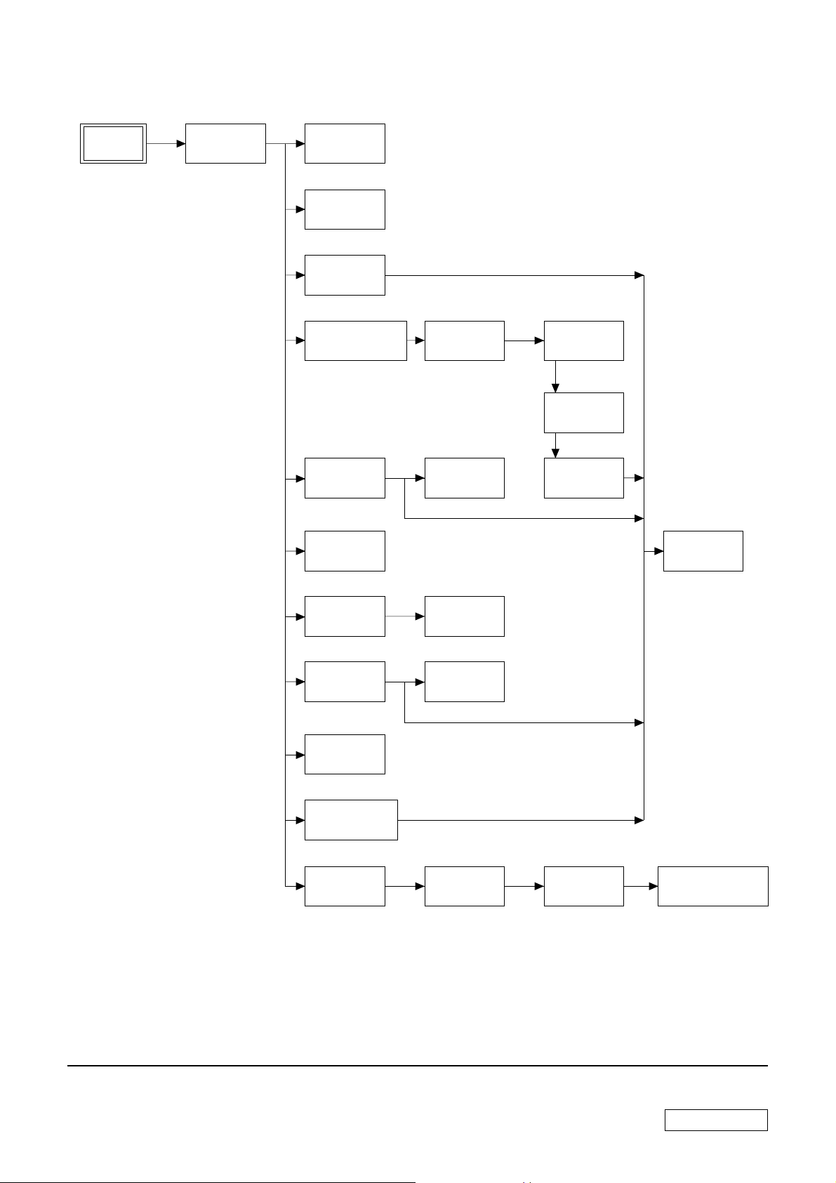
• FLOW CHART
SECTION 1
DISASSEMBLY
PCV-RZ
LEFT PANEL
ASS’Y
P1-2
OPTICAL
DRIVE
P1-3
SWITCHING
POWER
P1-4
HDD
P1-5
IFX-333 MULTI
CARD BOARD
P1-6
FDD
P1-10
CNX-235
BOARD
P1-7
CNX-180
BOARD
P1-11
CNX-183,
CNX-184
BOARD
P1-8, 9
SOUND CARD
(AUDIGY)
P1-18
MODEM
CARD
P1-19
DC FAN
(CHASSIS)
P1-12
DC FAN
(WITH
HEAT SINK)
P1-13
VGA CARD
P1-15
PCI SLOT
PANEL
P1-16
MOUNTED PWB
ENX-26 (US F)
P1-17
RIGHT PANEL
ASS’Y
P1-22
CPU
P1-14
MEMORY
P1-20
TOP PANEL
ASS’Y
P1-23
FRONT PANEL
ASS’Y
P1-24
MOTHER
BOARD
P1-21
SWX-120, SWX-159
SWITCH/LED
BOARD
P1-25
•Ps-s denotes the page concerned.
• HDD has a low resistance to vibration, requiring careful handling.
1-1
Confidential
PCV-RZ_M Series (AM)
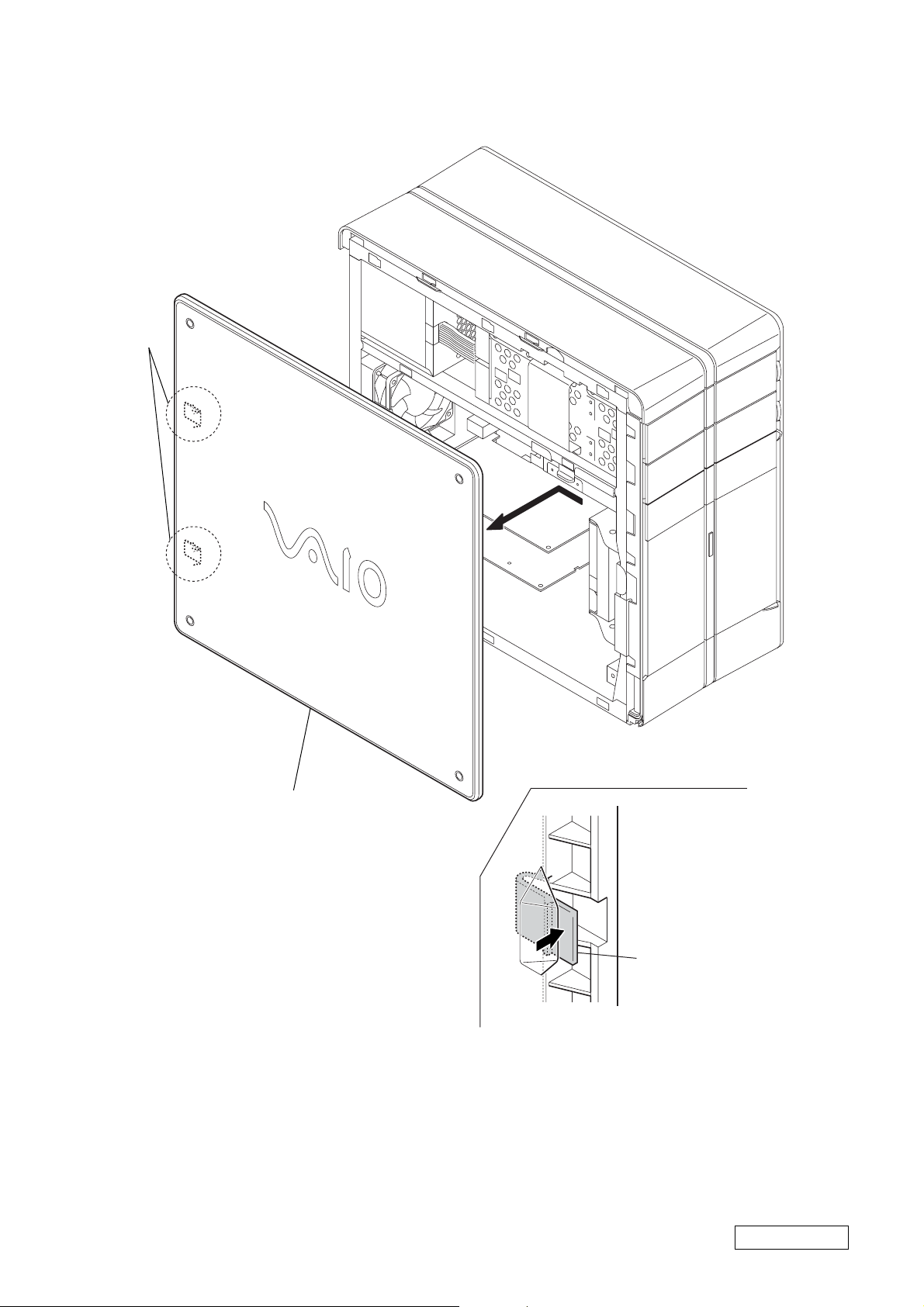
• LEFT PANEL ASS’Y
A
A
2
Remove the left panel ass’y
in the direction of arrow
A
.
1
two claws
: rear side (the enlargement figure of claws)
A
Confidential
1-2
PCV-RZ_M Series (AM)

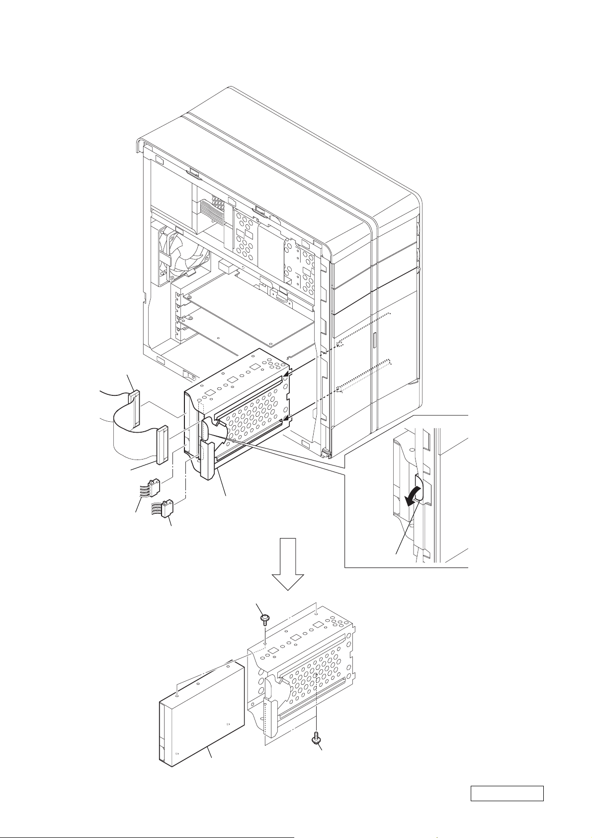
• OPTICAL DRIVE
1
harness
(switching power)
3
harness
(switching power)
2
harness (IDE CD/DVD)
4
harness
(IDE CD/DVD)
A
5
Pull the lever.
7
two screws
(PWH3
Remove the CD (bracket) ass’y
6
in the direction of arrow
×
5)
9
two screws
×
(PWH3
5)
A
.
8
upper optical drive
0
lower optical drive
1-3
Confidential
PCV-RZ_M Series (AM)
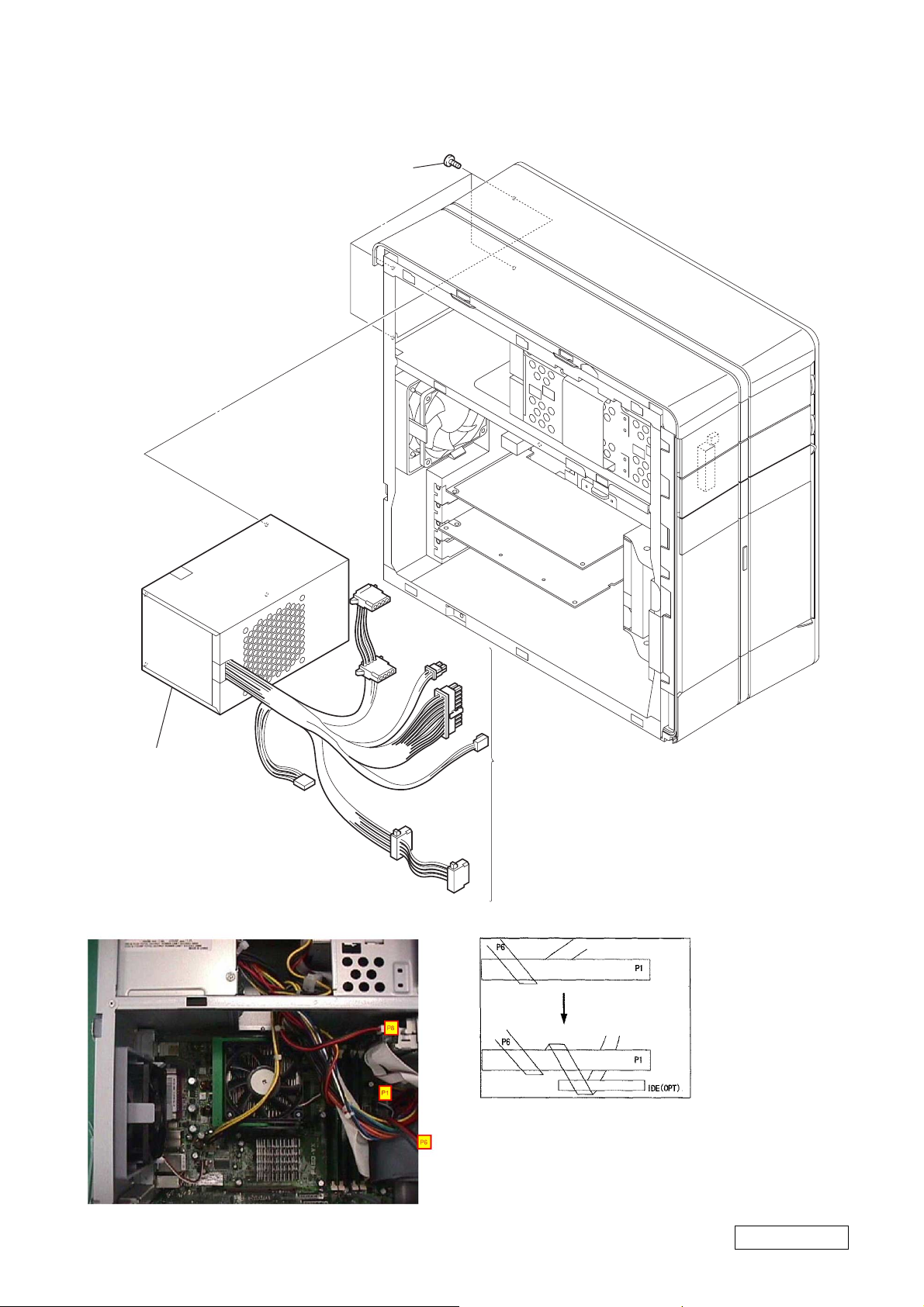
•SWITCHING POWER
2
four screws
(No.6-32UNC)
3
switching power
HARNESS LOCATION
1
Disconnect respective
power connectors.
1-4
Confidential
PCV-RZ_M Series (AM)
• HDD
3
harness
(IDE/ATA)
1
harness
(IDE/ATA)
4
power cable
2
harness
(switching power)
7
two screws
(SW) (No.6-32UNC)
6
HDD (bracket) ass’y
5
Pull the lever.
8
HDD
1-5
7
two screws
(SW) (No.6-32UNC)
Confidential
PCV-RZ_M Series (AM)

• IFX-333 MULTI CARD BOARD
1
harness
(USB2x3, MO)
2
3
screw
(SW) (No.6-32UNC)
harness
(OR, MS)
4
CR bracket block
5
two screws
(+PWH 3x5)
3
screw
(SW) (No.6-32UNC)
6
IFX-333 multi card board
1-6
Confidential
PCV-RZ_M Series (AM)

• CNX-235 BOARD
3
PCCD bracket
1
screw
(SW) (No.6-32UNC)
2
three screws
(SW) (No.6-32UNC)
1
screw
(SW) (No.6-32UNC)
4
CNX-235 board
1-7
Confidential
PCV-RZ_M Series (AM)
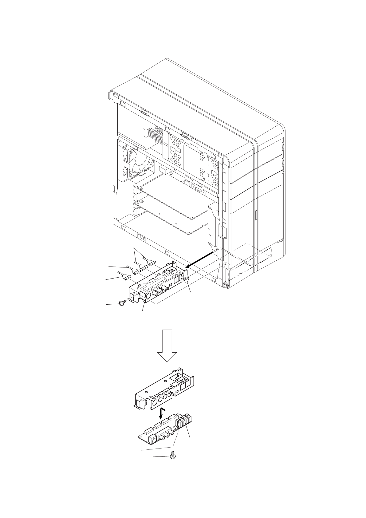
• CNX-183 BOARD
3
harness (USB2x3, MO)
2
harness (1394)
1
harness (audio)
4
screw
(SW) (No.6-32UNC)
5
6
Remove the connector bracket
in the direction of arrow
B
A
claw
A
.
7
three screws
(SW) (No.6-32UNC)
Remove the CNX-183 board
8
in the direction of arrow
1-8
B
.
Confidential
PCV-RZ_M Series (AM)
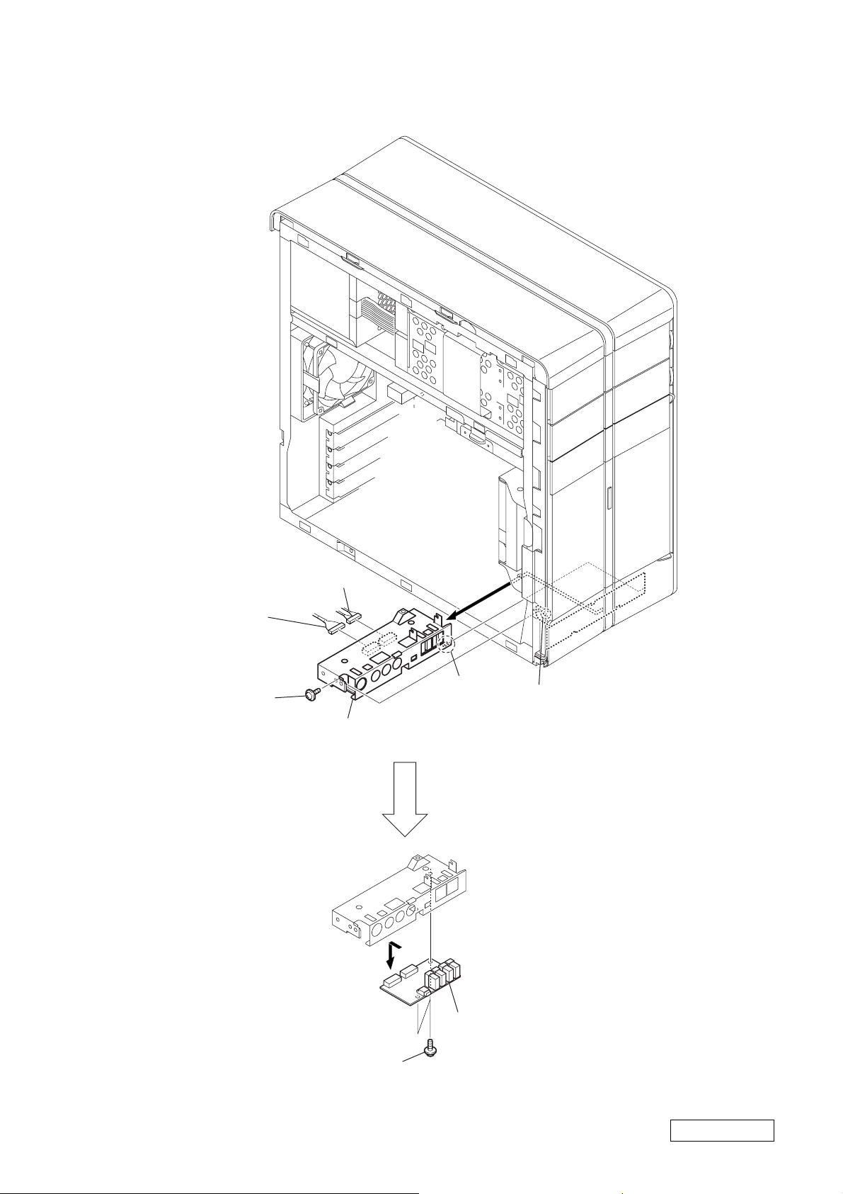
• CNX-184 BOARD
2
harness
(USB2, SC)
*
The MO model is using
the harness (USB × 4, MO)
1
harness (1394)
3
screw
(SW) (No.6-32UNC)
5
6
Remove the connector bracket
in the direction of arrow A.
A
claw
4
boss
7
two screws
(SW) (No.6-32UNC)
B
1-9
8
Remove the CNX-184 board
in the direction of arrow B.
Confidential
PCV-RZ_M Series (AM)
 Loading...