

PCV-RZ Series
SERVICE MANUAL
Ver. 6-2004A
Revision History
Lineup: PCV-RZ14G
PCV-RZ16G
1
PCV-RZ22G
1
PCV-RZ24G
1
PCV-RZ26G
2
PCV-RZ31G
2
PCV-RZ32G
2
PCV-RZ34G
2
PCV-RZ36G
2
PCV-RZ30GN2
2
PCV-RZ30GN4
PCV-RZ44G
3
PCV-RZ45G
3
3
PCV-RZ46G
PCV-RZ49
3
PCV-RZ40C1B
4
PCV-RZ40C1F
4
5
PCV-RZ50R
5
PCV-RZ54G
PCV-RZ56G
5
For American Area
US Model
Canadian Model
S400
9-874-359-06
PERSONAL COMPUTER VAIO
Information in this document is subject to change without notice.
CAUTION
Sony, VAIO and CLIE are trademarks or registered trademarks of
Sony. Microsoft, Windows, Windows Media, Outlook, Bookshelf
and other Microsoft products are trademarks or registered trademarks
of Microsoft Corporation in the United States and other countries.
The word Bluetooth and the Bluetooth logo are trademarks of
Bluetooth SIG, Inc. AMD, the AMD logo, other AMD product names
and combinations thereof are trademarks of Advanced Micro
Devices, Inc. Intel Inside logo, Pentium and Celeron are trademarks
or registered trademarks of Intel Corporation.Transmeta, the
Transmeta logo, Crusoe Processor, the Crusoe logo and
combinations thereof are trademarks of Transmeta Corporation in
the USA and other countries. Graffiti, HotSync, PalmModem, and
Palm OS are resistered trademarks, and the Hotsync logo and Palm
are trademarks of Palm, Inc. or its subsidiaries. (M) and Motrola
are trademarks of Motrora, Inc. Other Motrola products and services
with (R) mark like Dragomball are the trademarks of Motrola, Inc.
All other names of systems, products and services in this manual
are trademarks or registered trademarks of their respective o wners.
In this manual, the (TM) or (R) mark are not specified.
Danger of explosion if battery is incorrectly replaced.
Replace only with the same or equivalent type
recommended by the manufacturer.
Dispose of used batteries according
to the manufacturer’s instructions.
– 2 –
Confidential
PCV-RZ Series (AM)

TABLE OF CONTENTS
1. DISASSEMBLY
• Flow Chart................................................................ 1-1
• Left Panel Ass’y ....................................................... 1-2
• Optical Drive ............................................................ 1-3
• Switching Power ...................................................... 1-4
• HDD ......................................................................... 1-5
• IFX-294 Memory Stick Board/
IFX-333 Multi Card Board ...................................... 1-6
• CNX-235 Board ....................................................... 1-7
• CNX-183 Board ....................................................... 1-8
• CNX-184 Board ....................................................... 1-9
• FDD .......................................................................... 1-10
• CNX-180 Board ....................................................... 1-11
• DC Fan (Chassis) ..................................................... 1-12
• DC Fan (with Heat Sink) ......................................... 1-13
• CPU .......................................................................... 1-14
•VGA Card................................................................. 1-15
• PCI Slot Panel .......................................................... 1-16
• Mounted PWB ENX-15,
Mounted PWB ENX-20 (US F),
Mounted PWB ENX-26 (US F)............................... 1-17
• Sound Card (AUDIGY) ........................................... 1-18
• Modem Card............................................................. 1-19
• Memory .................................................................... 1-20
• Mother Board ........................................................... 1-21
• Right Panel Ass’y..................................................... 1-22
•Top Panel Ass’y........................................................ 1-23
•Front Panel Ass’y ..................................................... 1-24
• SWX-120, SWX-159, SWX-160
Switch/LED Board ................................................... 1-25
2. FRAME HARNESS
• Frame Harness Diagram and Jumper Setting
of Mother Board ....................................................... 2-1
3. REPAIR PARTS LIST
3-1. Exploded Vie w
(Mother Board (GL)/(WA)/(MO, GBE) Ass’y) ...... 3-1
3-2. Exploded Vie w
(Mother Board (MO2, GBE/WOAU)/
(MU, PSC/GB/WOAU) Ass’y) ................................ 3-3
3-3. Accessories............................................................... 3-5
3-4. Basic List.................................................................. 3-7
3-5. Substitution List ....................................................... 3-21
History of the changes is shown as the “Revision
History” at the end of this data.
– 3 –
Confidential
PCV-RZ Series (AM)
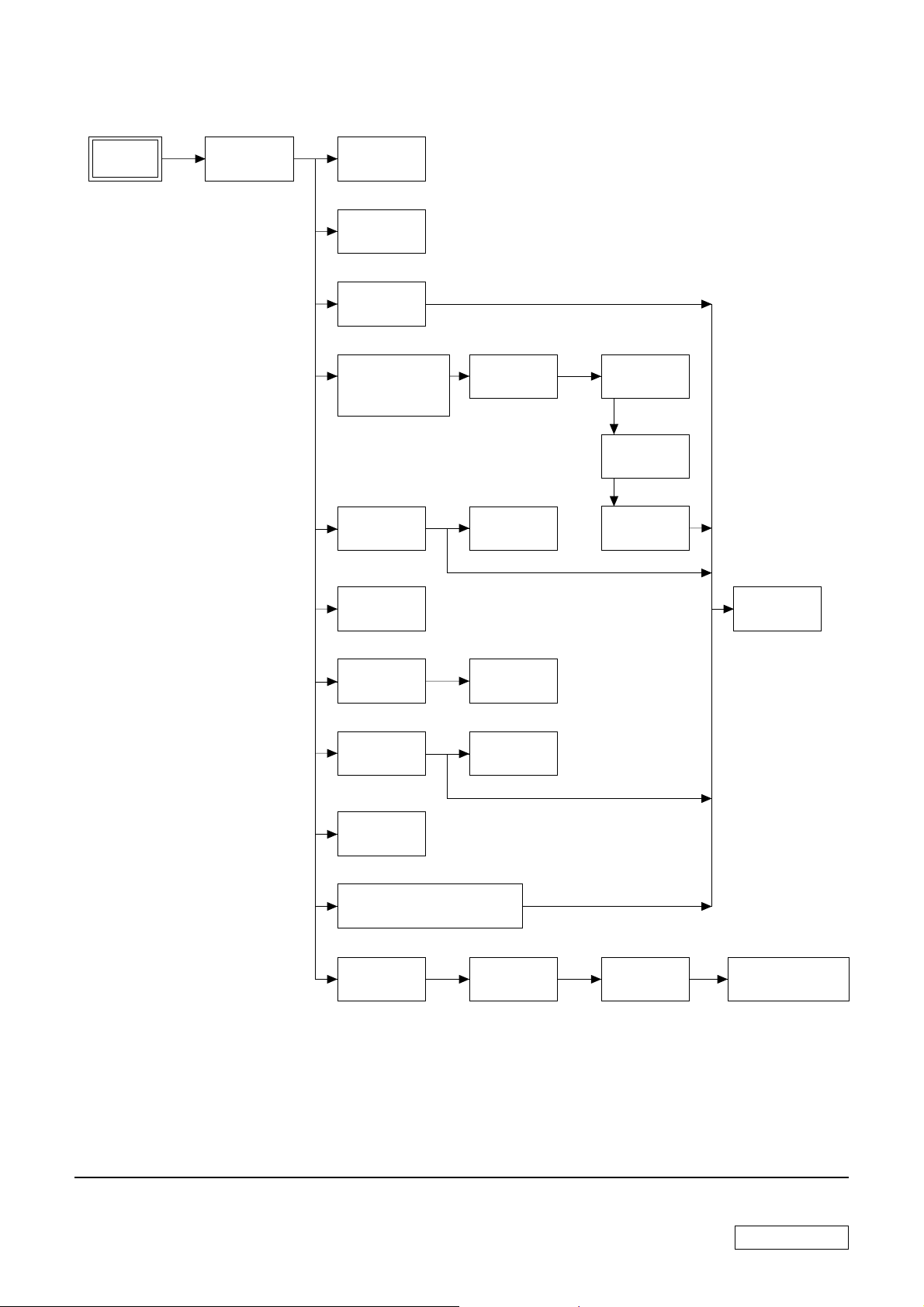
• FLOW CHART
SECTION 1
DISASSEMBLY
PCV-RZ
LEFT PANEL
ASS’Y
P1-2
OPTICAL
DRIVE
P1-3
SWITCHING
POWER
P1-4
HDD
P1-5
IFX-294 MEMORY
STICK BOARD/
IFX-333 MULTI
CARD BOARD
P1-6
FDD
P1-10
CNX-235
BOARD
P1-7
CNX-180
BOARD
P1-11
CNX-183,
CNX-184
BOARD
P1-8, 9
SOUND CARD
(AUDIGY)
P1-18
MODEM
CARD
P1-19
DC FAN
(CHASSIS)
P1-12
DC FAN
(WITH
HEAT SINK)
P1-13
VGA CARD
P1-15
PCI SLOT
PANEL
P1-16
MOUNTED PWB ENX-15,
MOUNTED PWB ENX-20 (US F),
MOUNTED PWB ENX-26 (US F)
P1-17
RIGHT PANEL
ASS’Y
P1-22
CPU
P1-14
MEMORY
P1-20
TOP PANEL
ASS’Y
P1-23
FRONT PANEL
ASS’Y
P1-24
MOTHER
BOARD
P1-21
SWX-120, SWX-159,
SWX-160 SWITCH/
LED BOARD
P1-25
•Ps-s denotes the page concerned.
• HDD has a low resistance to vibration, requiring careful handling.
1-1
Confidential
PCV-RZ Series (AM)
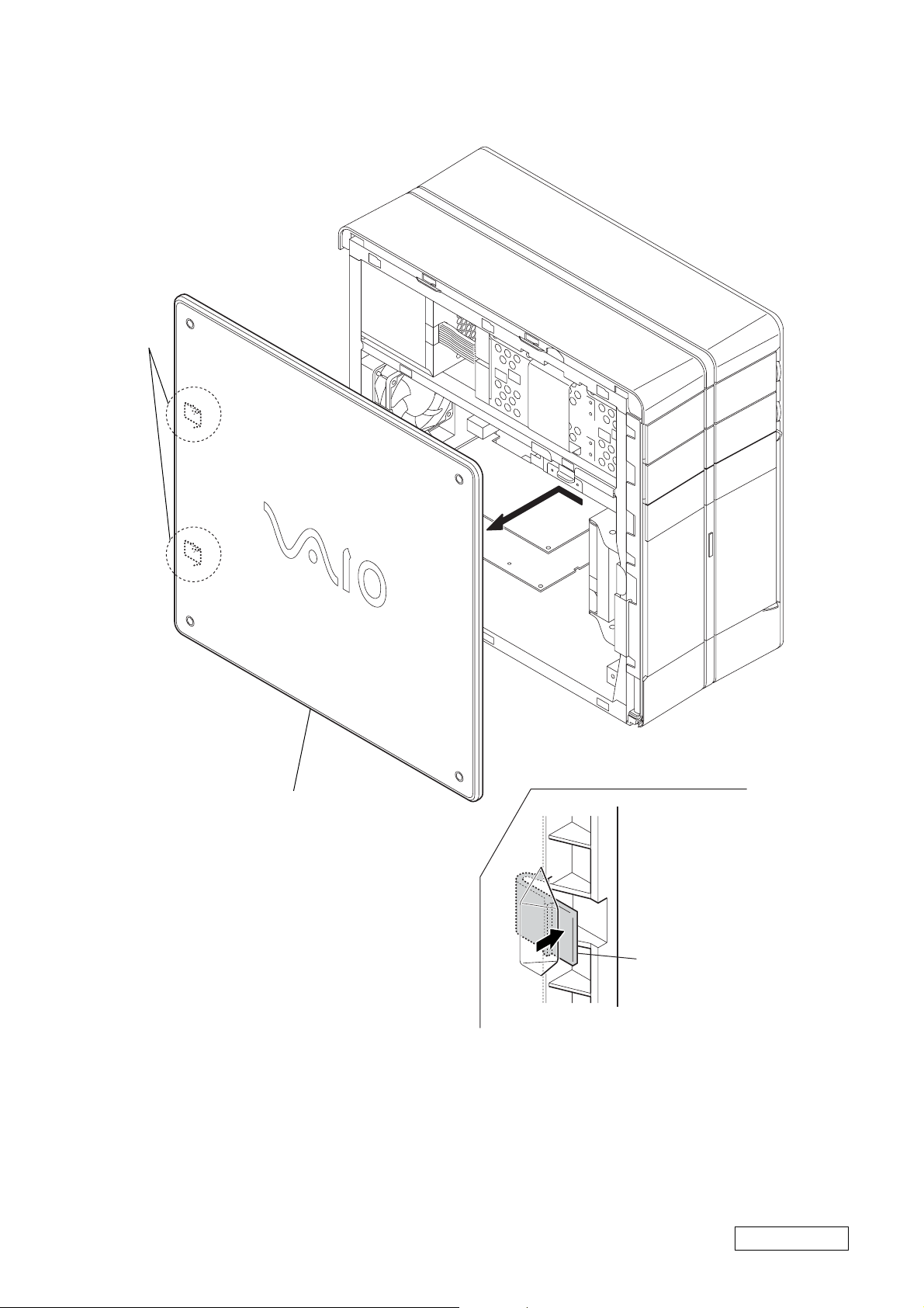
• LEFT PANEL ASS’Y
A
A
2
Remove the left panel ass’y
in the direction of arrow
A
.
1
two claws
: rear side (the enlargement figure of claws)
A
Confidential
1-2
PCV-RZ Series (AM)
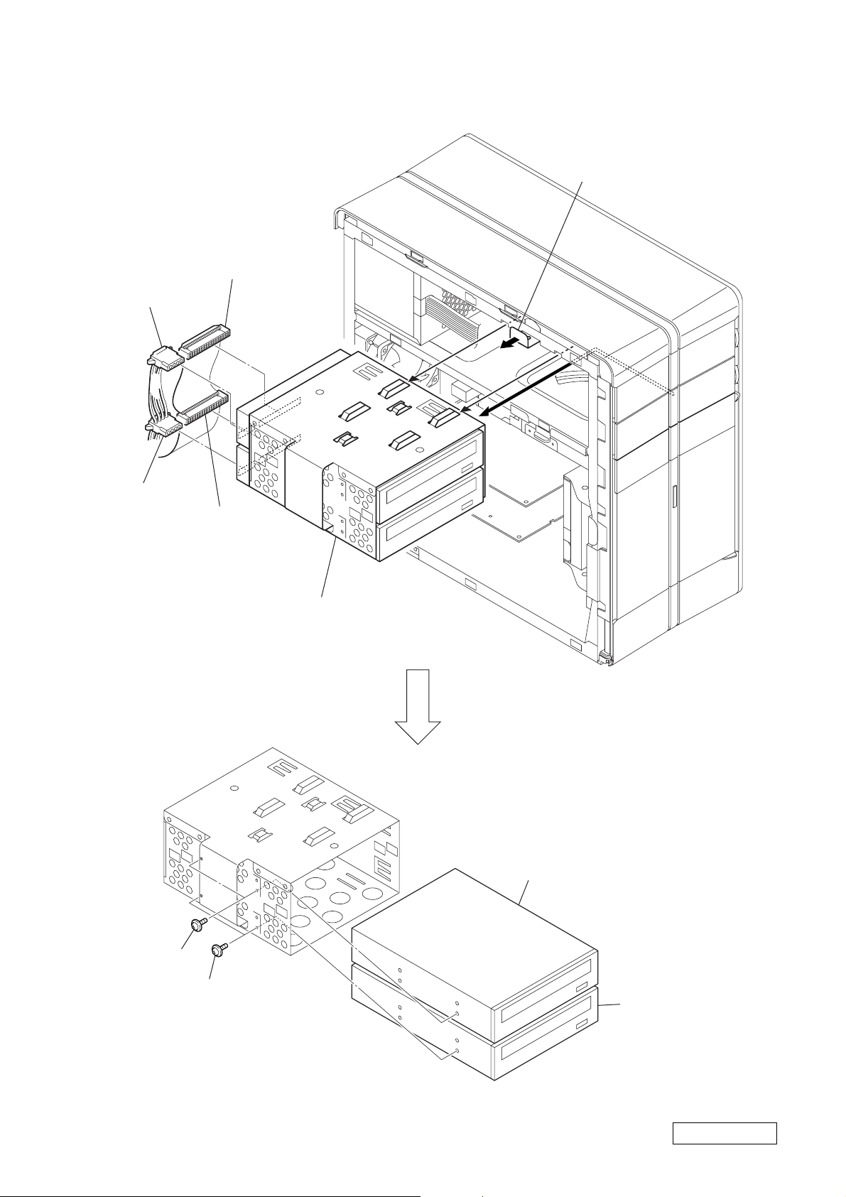
• OPTICAL DRIVE
1
harness
(switching power)
3
harness
(switching power)
2
harness (IDE CD/DVD)
4
harness
(IDE CD/DVD)
A
5
Pull the lever.
7
two screws
(PWH3
6
Remove the CD (bracket) ass’y
in the direction of arrow
×
5)
9
two screws
(PWH3
×
5)
A
.
8
upper optical drive
0
lower optical drive
1-3
Confidential
PCV-RZ Series (AM)

•SWITCHING POWER
2
four screws
(No.6-32UNC)
3
switching power
HARNESS LOCATION
1
Disconnect respective
power connectors.
1-4
Confidential
PCV-RZ Series (AM)
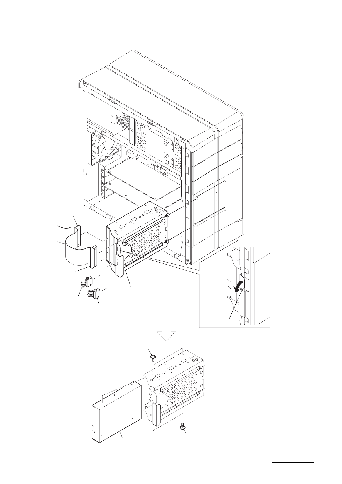
• HDD
3
harness
(IDE/ATA)
1
harness
(IDE/ATA)
4
power cable
2
harness
(switching power)
7
two screws
(SW) (No.6-32UNC)
6
HDD (bracket) ass’y
5
Pull the lever.
8
HDD
1-5
7
two screws
(SW) (No.6-32UNC)
Confidential
PCV-RZ Series (AM)
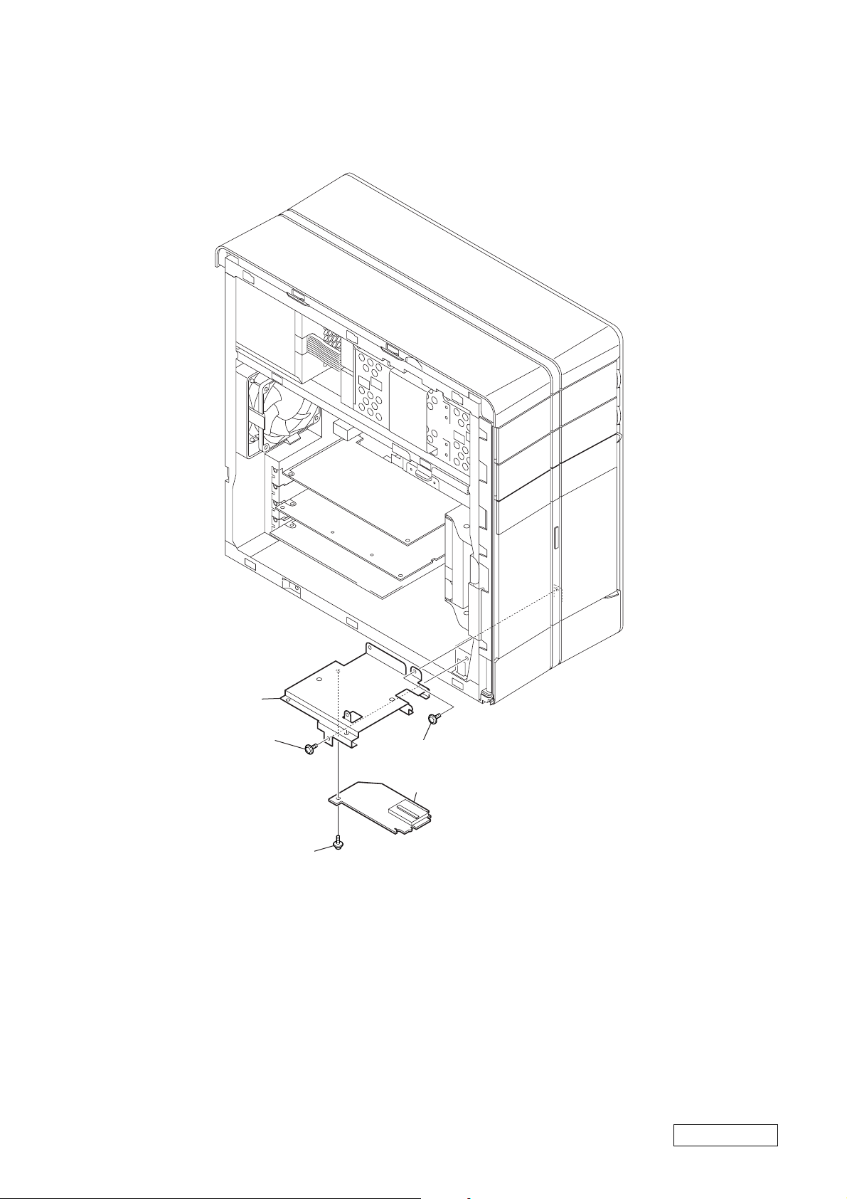
• IFX-294 MEMORY STICK BOARD/
IFX-333 MULTI CARD BOARD
1
harness
(USB2x3, MO)
2
3
screw
(SW) (No.6-32UNC)
harness
(OR, MS)
4
CR bracket block
5
two screws
(+PWH 3x5)
3
screw
(SW) (No.6-32UNC)
6
IFX-294 memory stick board/
IFX-333 multi card board
1-6
Confidential
PCV-RZ Series (AM)
• CNX-235 BOARD
3
PCCD bracket
1
screw
(SW) (No.6-32UNC)
2
three screws
(SW) (No.6-32UNC)
1
screw
(SW) (No.6-32UNC)
4
CNX-235 board
1-7
Confidential
PCV-RZ Series (AM)

• CNX-183 BOARD
3
harness (USB2, SC)/(USB2x4, MO)/
(USB2x3, MO)
2
harness (1394)
1
harness (audio)
4
screw
(SW) (No.6-32UNC)
5
6
Remove the connector bracket
in the direction of arrow
B
A
claw
A
.
7
three screws
(SW) (No.6-32UNC)
8
Remove the CNX-183 board
in the direction of arrow
1-8
B
.
Confidential
PCV-RZ Series (AM)
• CNX-184 BOARD
2 harness (USB2x3, MO)
1 harness (1394)
3 screw
(SW) (No.6-32UNC)
A
5 claw
6 Remove the connector bracket in the direction of arrow A.
B
4 boss
7 two screws
(SW) (No.6-32UNC)
1-9
8 Remove the CNX-184 board
in the direction of arrow B.
Confidential
PCV-RZ Series (AM)
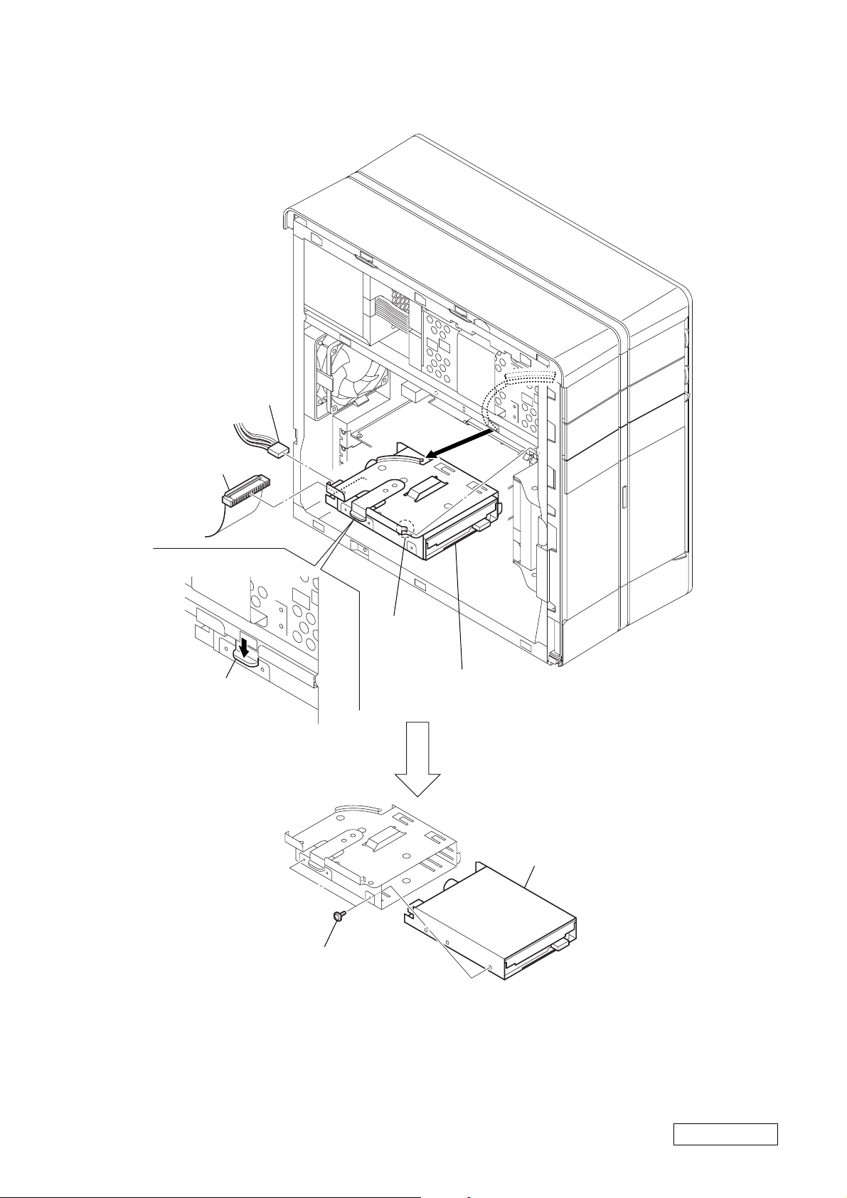
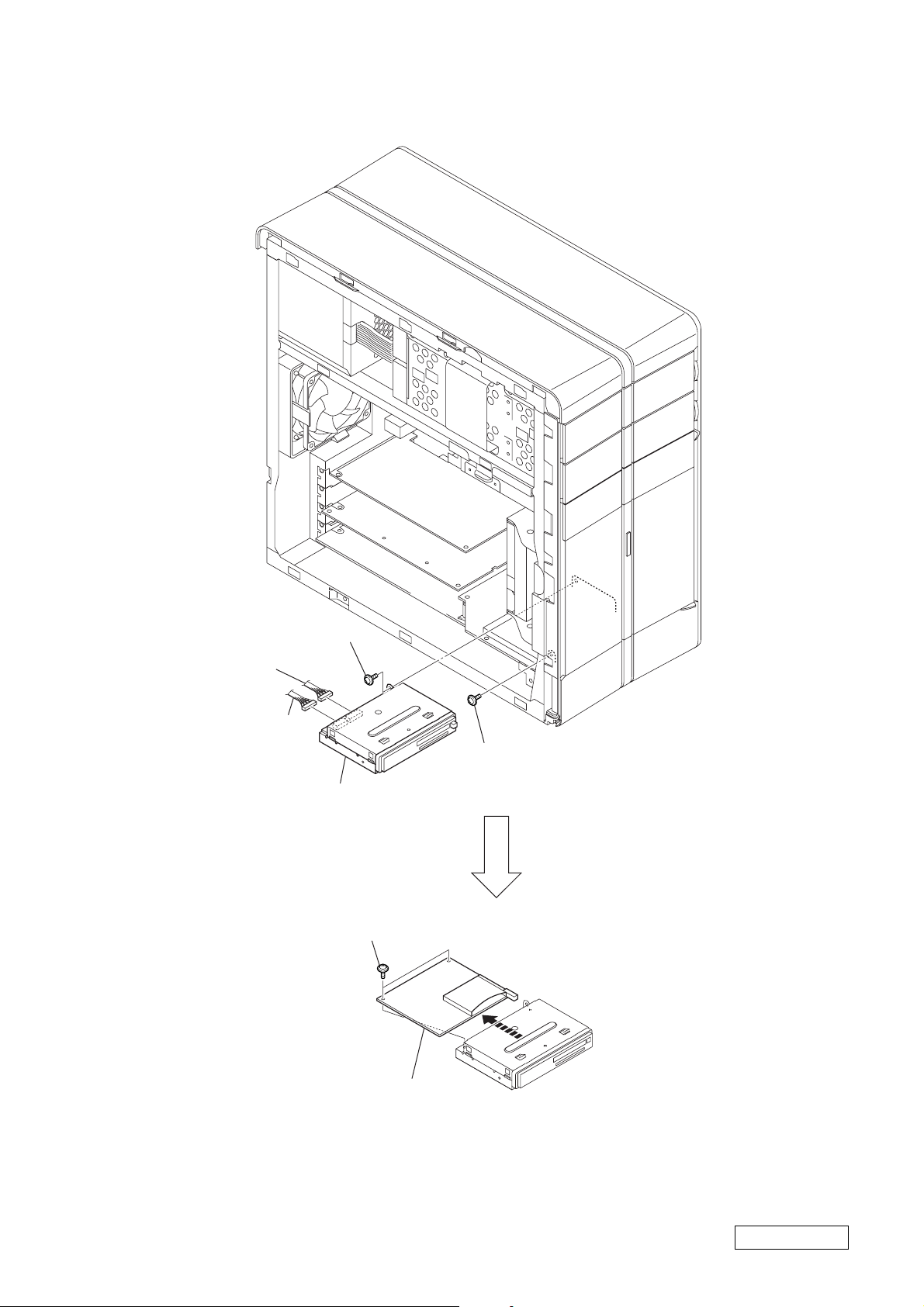
• FDD
2
harness
(switching power)
1
harness (FDD)
A
3
Push the lever.
6
two screws
(PWH3
5
claw
4
Remove the FD (bracket) ass’y
in the direction of arrow
×
5)
A
.
7
FDD
1-10
Confidential
PCV-RZ Series (AM)
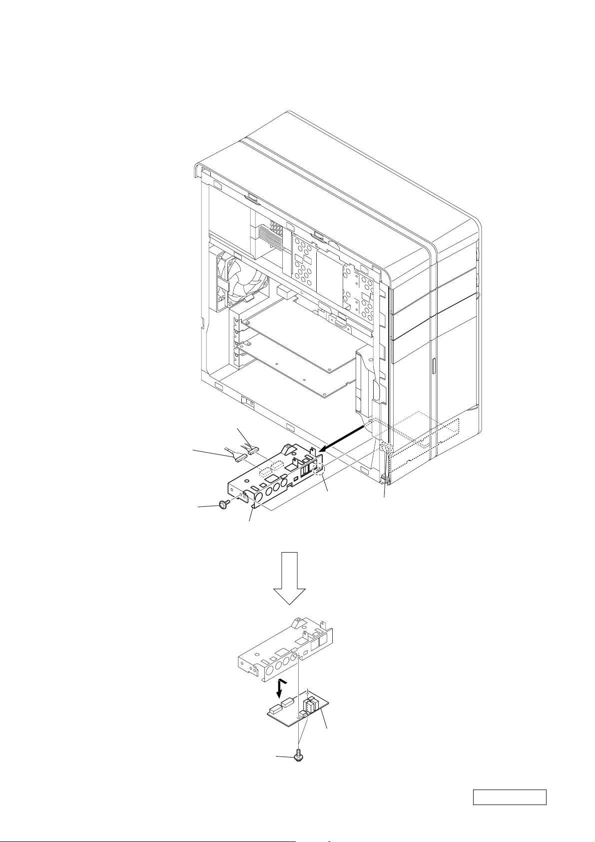
• CNX-180 BOARD
s
3
two claw
2
screw
(SW) (No.6-32UNC)
1
harness (MS, SIO)
4
Remove the CNX-180 board
in the direction of the arrow .
1-11
Confidential
PCV-RZ Series (AM)
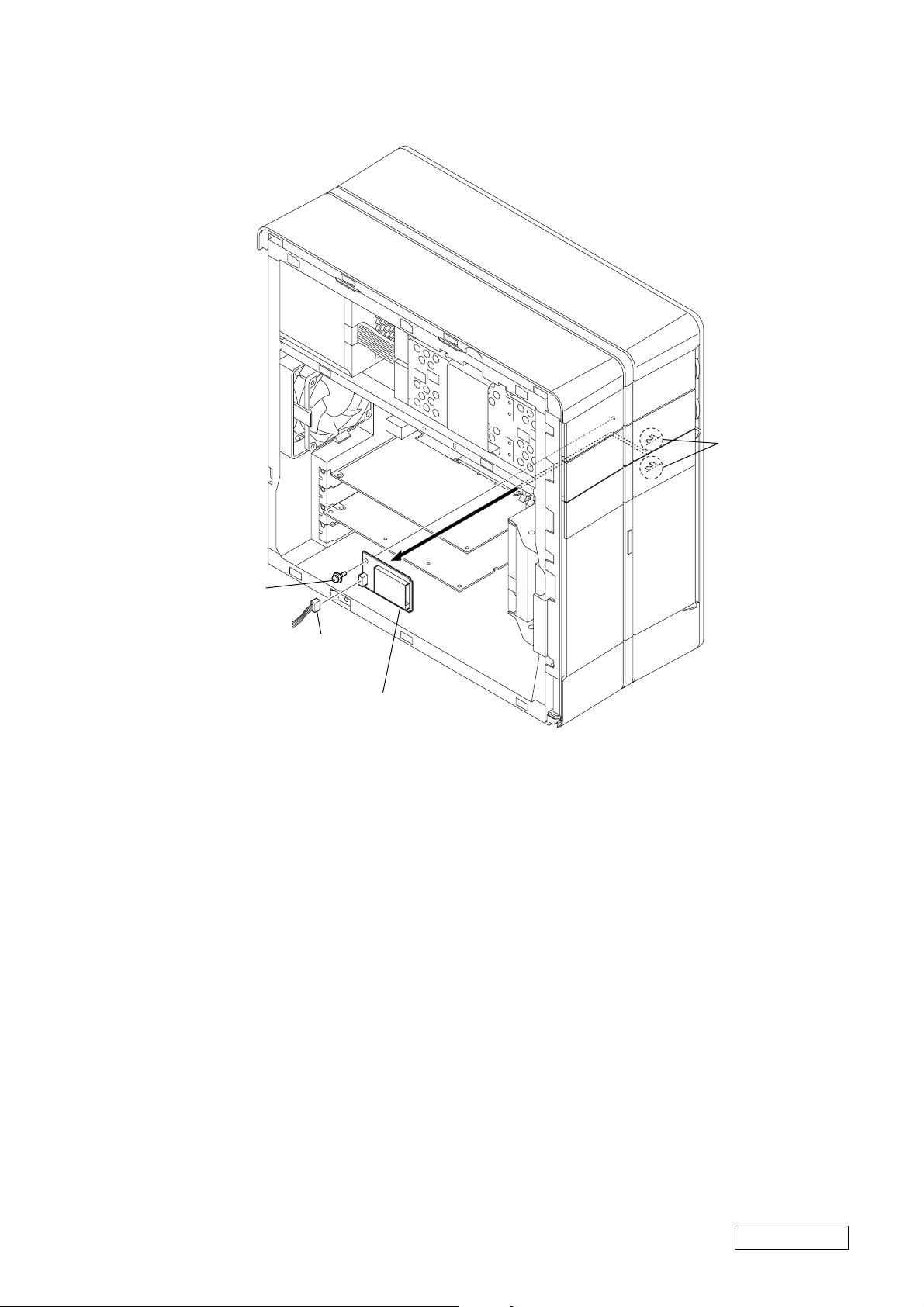
• DC FAN (CHASSIS)
3
four claws
1
harness
2
Lift the fan bracket,
pushing two claws.
4
Remove the fan bracket
in the direction of the arrow.
5
two claws
5
two claws
1-12
6
DC fan (chassis)
Confidential
PCV-RZ Series (AM)

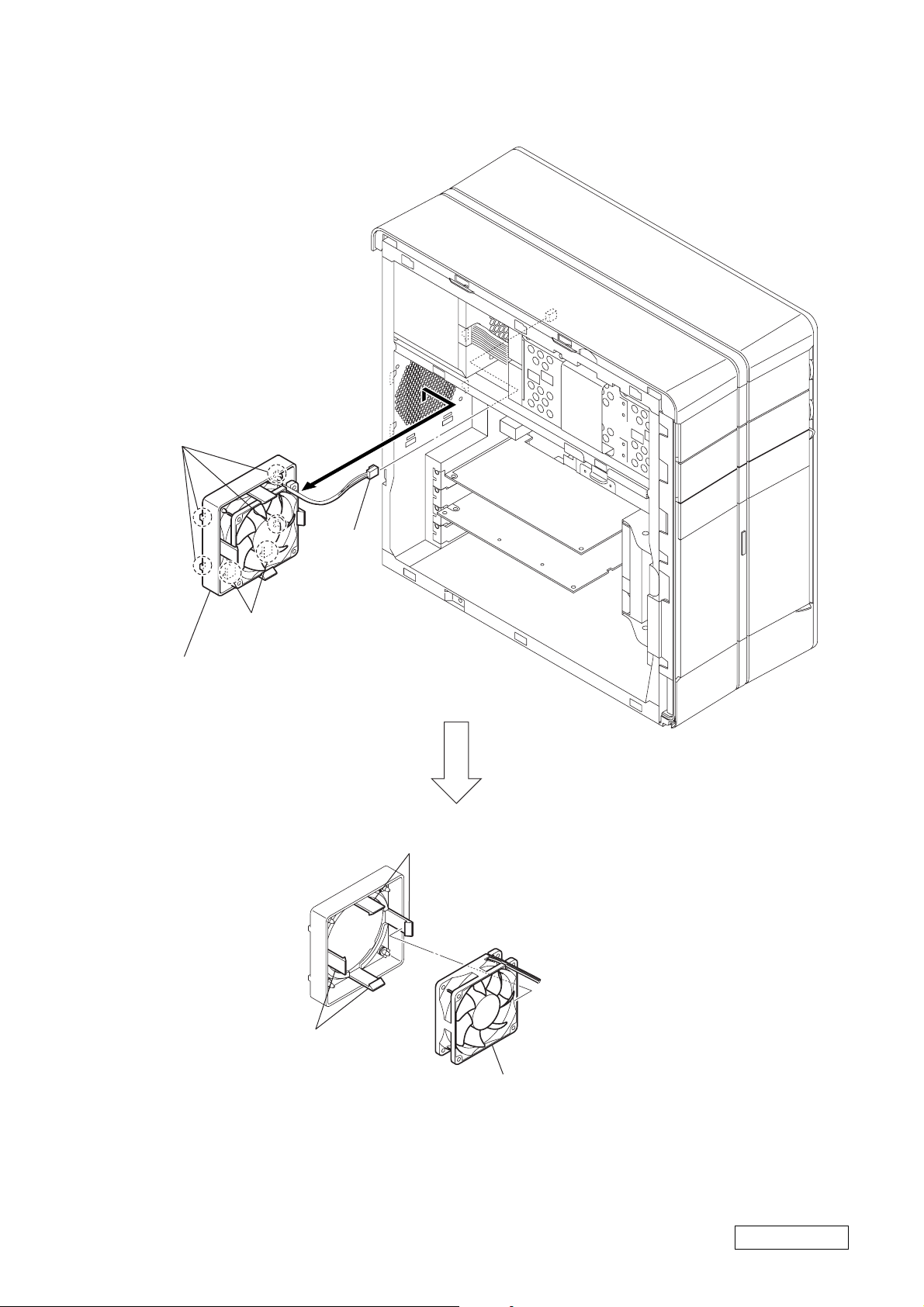
• DC FAN (WITH HEAT SINK)
p
3
DC fan
(with heat sink)
2
clip
2
cli
3
3
DC fan
(with heat sink)
3
Claw
Claw
2
Lift up the handle.
3
Claw
1
3
harness
Claw
1-13
1
harness
Confidential
PCV-RZ Series (AM)

• CPU
1
Elect the lever
in the direction of arrow
A
2
CPU
A
.
Note : When heat sink is removed from CPU,
install new ones after thermal diffusion
grease is wiped off and silicon compound
is applied to the place shown in the figure.
Thermal diffusion grease : silicon compound (G-765) 90G
Amount to apply : 0.5 g (as the same size as the tip of a match) (Pentium 4)
Take care not to apply the grease
*
to any other places because it has
high conductivity.
grease
(in the surface at the
splatter)
1-14
Confidential
PCV-RZ Series (AM)

•VGA CARD
3
Push the clip.
AGP1
1
power cable
4
VGA card
2
screw
(SW) (No.6-32UNC)
1-15
Confidential
PCV-RZ Series (AM)

• PCI SLOT PANEL
2
PCI slot panel
1
screw
(SW) (No.6-32UNC)
1-16
Confidential
PCV-RZ Series (AM)

• MOUNTED PWB ENX-15, MOUNTED PWB ENX-20 (US F),
MOUNTED PWB ENX-26 (US F)
3
screw
(SW) (No.6-32UNC)
4
MOUNTED PWB ENX-15,
MOUNTED PWB ENX-20 (US F)
2
harness
(YU audio)
1
harness (audio)
CN9
PCI2
CN8
1
harness (audio)
3
MOUNTED PWB
ENX-26 (US F)
2
screw
(SW) (No.6-32UNC)
1-17
*
An illustration is MOUNTED PWB ENX-15.
Although the form of MOUNTED PWB ENX-20
(US F) differs from an illustration, how to remove
does not have a difference.
Confidential
PCV-RZ Series (AM)

• SOUND CARD (AUDIGY)
2
sound card (audigy)
PCI3
1
screw
(SW) (No.6-32UNC)
1-18
Confidential
PCV-RZ Series (AM)

• MODEM CARD
1
CNR1
modem card
1-19
Confidential
PCV-RZ Series (AM)

• MEMORY
1
Open clip.
2
memory
Note 1: In opening the clips,
hold lightly the top of the memories
with your fingers to prevent a drop.
Note 2: In removing the memories,
always start from the one
having largest bank number.
1
Open clip.
MEMORY INSTALLATION
Note1 : With the clips left open, insert the memory so that
boss of DIMM socket engage with slot of memory.
Note2 : Make sure that clips are closed when the memory
were inserted completely.
Note3 : Insert the memory, starting from the one having
smallest bank number.
clip
memory
boss
DIMM socket
clip
1-20
Confidential
PCV-RZ Series (AM)

•MOTHER BOARD
1
three screws
(SW) (No.6-32UNC)
1
two screws
(SW) (No.6-32UNC)
three screws
1
(SW) (No.6-32UNC)
5
mother board
4
2
3
1-21
Confidential
PCV-RZ Series (AM)

• RIGHT PANEL ASS’Y
1
two claws
2
Remove the right panel ass’y
in the direction of arrow
A
A
.
1-22
Confidential
PCV-RZ Series (AM)

•TOP PANEL ASS’Y
7
top panel ass’y
2
claw
4
claw
1
claw
3
claw
5
claw
6
claw
1-23
Confidential
PCV-RZ Series (AM)

•FRONT PANEL ASS’Y
y
3
two claws
1
two claws
2
two claws
4
front panel ass’
1-24
Confidential
PCV-RZ Series (AM)

•SWX-120, SWX-159, SWX-160 SWITCH/LED BOARD
2
screw
(SW) (No.6-32UNC)
3
two claws
1
harness (SW/LED)
4
Remove the SWX-120, SWX-159 SWITCH/
LED board in the direction of the arrow .
*
An illustration is SWX-120 board.
Although the form of SWX-159 SWITCH/
LED board differs from an illustration, how
to remove does not have a difference.
4
two claws
1
LED unit
3
5
Remove the SWX-160 SWITCH/LED
board in the direction of the arrow .
1-25
(END)
2
harness (SW/LED)
two screw
(SW) (No.6-32UNC)
Confidential
PCV-RZ Series (AM)

S
1
3
CMOS CLR
1-2: CMOS CLR
2-3: RTC CLR
P5
POWER
FDD IF
FDD
IDE
AUDIO
OPTICAL DRIVE
OPTICAL DRIVE
POWER
IDE
HDD
Harness (FDD)
Harness
(IDE CD/DVD)
Harness
(IDE/ATA66)
P8
P4
P6
P7
EXTENSION
HDD
P2
P1
P3
5inch Bay1
(Upper side)
(Front side)
(Lower side)
(Rear side)
5inch Bay2
HDD Bay1
HDD Bay2
POWER
IDE
POWER
IDE POWER
MOTHER BOARD (GL)
P4S533-VX (W/O VGA)
MOTHER BOARD (GL)
P4S533-VX (W/O VGA)
SWX-120
PC BOARD
Rear Panel
MOUSE
KEYBOARD
USB X2
MONITOR
i. LINK
S400
6 pin
PRINTER
Rear
POWER SUPPLY
AC INPUT
100V – 240V
4.7A
50/60Hz
HEAD
PHONES
LINE IN
MIC
Harness (USB2, SC)
Harness
(SW/LED)
VGA CARD
CPU
CNR
CNR Connector
CNR
J2
J1
LINE
PHONE
CNR MODEM
(FCC) CARD
Power
Switch
HDD
LED
POWER
LED
DVD-ROM/
CD-RW
LED
CNX-180 PC BOARD
U1
CN1
AGP
SOCKET
478
HEATSINK WITH FAN
From board to connector
(direct connection)
Harness
(with connectors on both ends)
Harness (soldering on either end)
MEMORY STICK
CONNECTOR
PCI2
ENX-15 BOARD
CN8
CN9
CN1 CN2 CN3
LR
i.LINK
S400
4 pin
USB
VIDEO
S VIDEO
VIDEO OUTPUT VIDEO 1 INPUT
CN4 CN6
AUDIO
S VIDEO/
VIDEO
S VIDEO/
VIDEO
AUDIO
VHF/UHF
PCI
Harness
(YU AUDIO)
Harness (1394)
CNX-183
PC BOARD
(Front Connector)
U3
CN2
CN1
U2
U1 PANEL1
CN1
Harness (AUDIO)
LINE
1
4
ACT
NETWORK
LINK
Harness (MS, SIO)
DDR Socket (×3)
DDR1
DDR2
DDR3
DDR1
DDR2
DDR3
CN5
110
14
1
4
MS-CON2
16
1
1
20
18
140
1
40
134
MEMORY BOARD
MEMORY BOARD
MEMORY BOARD
SECTION 2
FRAME HARNESS
• FRAME HARNESS DIAGRAM AND JUMPER SETTING OF MOTHER BOARD
The Mother board of service parts can be used without changing factory jumper setting, when it was replaced for service.
0 CAUTION
Do not change the jumper with the power turned
on.
Before changing the jumper , turn off the power and
disconnect the power cord from the set.
Confidential
2-22-1
PCV-RZ Series (AM)

CNX-183
PC BOARD
(Front Connector)
S VIDEO
S
CN2
U3
VIDEO
i.LINK
LR
LINE
CN1
S400
4 pin
U2
U1 PANEL1
USB
CN1
AGP
SOCKET
478
VGA CARD
CPU
MONITOR
KEYBOARD
Rear Panel
MOUSE
Rear
MOTHER BOARD (WA)
P4S533-VL (W/O VGA)
Harness (AUDIO)
ENX-15 BOARD
CN1 CN2 CN3
110
CN9
CN4 CN6
VIDEO OUTPUT VIDEO 1 INPUT
AUDIO
S VIDEO/
VIDEO
AUDIO
S VIDEO/
VIDEO
14
CN8
VHF/UHF
1
CN5
PCI2
CNR
CNR Connector
CNR MODEM
CNR
(FCC) CARD
LINE
PHONE
MEMORY STICK
CONNECTOR
J2
J1
U1
MS-CON2
CNX-180 PC BOARD
Harness
(SW/LED)
The Mother board of service parts can be used without changing factory jumper setting, when it was replaced for service.
0 CAUTION
Do not change the jumper with the power turned
on.
Before changing the jumper , turn off the power and
disconnect the power cord from the set.
Harness
(YU AUDIO)
4
PCI
Harness (USB2, SC)
16
CMOS CLR
Harness (MS, SIO)
CN1
1-2: CMOS CLR
2-3: RTC CLR
POWER
DVD-ROM/
SWX-120
PC BOARD
Harness (1394)
4
1
1
1
20
1
3
Power
Switch
LED
CD-RW
LED
HDD
LED
18
140
1
134
40
DDR1
DDR2
MOTHER BOARD (WA)
P4S533-VL (W/O VGA)
HEATSINK WITH FAN
DDR Socket (×2)
DDR1
DDR2
Harness (FDD)
Harness
(IDE/ATA66)
MEMORY BOARD
MEMORY BOARD
P2
Harness
(IDE CD/DVD)
IDE
EXTENSION
IDE
MONITOR
i. LINK
S400
6 pin
USB X2
HEAD
PHONES
POWER SUPPLY
P1
P3
FDD IF
FDD
AUDIO
POWER
(Upper side)
5inch Bay1
OPTICAL DRIVE
IDE
POWER
5inch Bay2
OPTICAL DRIVE
IDE POWER
(Rear side)
HDD Bay1
HDD
HDD
POWER
HDD Bay2
POWER
(Lower side)
P6
P7
(Front side)
2-42-3
ACT
NETWORK
LINK
PRINTER
LINE IN
MIC
AC INPUT
100V – 240V
4.7A
50/60Hz
P8
P5
P4
From board to connector
(direct connection)
Harness
(with connectors on both ends)
Harness (soldering on either end)
Confidential
PCV-RZ Series (AM)

CNX-183
PC BOARD
(Front Connector)
S VIDEO
S
CN2
U3
VIDEO
LR
LINE
CN1
U1 PANEL1
i.LINK
S400
4 pin
U2
CN1
USB
CN2
PANEL2
AGP
SOCKET
478
VGA CARD
CPU
MONITOR
KEYBOARD
Rear Panel
MOUSE
PRINTER
Rear
MOTHER BOARD (MO)
P4SD-VX
ENX-20 (US F)
BOARD
CN3
AUDIO INPUT
L
LINE
PHONE
MEMORY STICK
CONNECTOR
CNX-180 PC BOARD
Harness (AUDIO)
110
CN1
VIDEO 1 INPUT
S VIDEOVIDEOR
CNR MODEM
(FCC) CARD
J2
J1
U1
Harness
(YU AUDIO)
14
CN5
VHF/UHF
(Antenna)
CNR
CNR Connector
CNR
MS-CON2
PCI
PCI2
Harness (MS, SIO)
4
1
Harness (1394)
Harness (USB2x4, MO)
16
1
1
20
3
1
CMOS CLR
1-2: CMOS CLR
2-3: NORMAL
XMM2
XMM3
140
1
134
40
XMM1
XMM4
MOTHER BOARD (MO)
P4SD-VX
HEATSINK WITH FAN
XMM Socket (×4)
XMM1
XMM2
XMM3
XMM4
MEMORY BOARD
MEMORY BOARD
MEMORY BOARD
P2
P1
i. LINK
S400
6 pin
USB
X2
HEAD
PHONES
P3
ACT
NETWORK
LINK
LINE IN
MIC
AC INPUT
100V – 240V
4.7A
50/60Hz
POWER SUPPLY
The Mother board of service parts can be used without changing factory jumper setting, when it was replaced for service.
0 CAUTION
Do not change the jumper with the power turned
on.
Before changing the jumper , turn off the power and
disconnect the power cord from the set.
Harness (SW/LED)
CN1
SWX-120
PC BOARD
Power
Switch
POWER
LED
DVD-ROM/
CD-RW
LED
HDD
LED
Harness (FDD)
Harness
(IDE CD/DVD)
Harness
(IDE/ATA66)
FDD IF
AUDIO
OPTICAL DRIVE
FDD
IDE
OPTICAL DRIVE
IDE POWER
(Rear side)
HDD Bay1
POWER
HDD
HDD
HDD Bay2
POWER
IDE
EXTENSION
IDE
POWER
(Upper side)
5inch Bay1
POWER
5inch Bay2
(Lower side)
P6
P7
(Front side)
P8
P5
P4
From board to connector
(direct connection)
Harness
(with connectors on both ends)
Harness (soldering on either end)
Confidential
2-62-5
PCV-RZ Series (AM)

CNX-183
PC BOARD
(Front Connector)
S VIDEO
S
CN2
U3
LR
VIDEO
CN1
U1 PANEL1
LINE
i.LINK
S400
4 pin
U2
CN1
USB
CN2
PANEL2
AGP
VGA CARD
SOCKET
478
MONITOR
DVI
CPU
KEYBOARD
Rear Panel
MOUSE
PRINTER
Rear
MOTHER BOARD (MO2)
P4SD-VX
ENX-26 (US F) BOARD
CN3
AUDIO INPUT
PHONE
LINE
VIDEO 1 INPUT
L
J1
J2
Harness (OR, MS)
PC CARD
MEMORY
STICK
IFX-294 MEMORY
Harness (AUDIO)
110
CN1
S VIDEOVIDEOR
14
CN5
CP1
VHF/UHF
(Antenna)
CNR
CNR Connector
CNR
CNR MODEM
(PRIMARY/SC)
CARD
CON5
USB_CON1
STICK BOARD
PCI
PCI1
Harness (1394)
1
Harness (USB2X3, MO)
6
1
16
1
20
3
1
CMOS CLR
1-2: CMOS CLR
2-3: NORMAL
XMM1
XMM2
XMM3
XMM4
140
1
1
40
34
MOTHER BOARD (MO2)
P4SD-VX
HEATSINK WITH FAN
XMM Socket (×4)
XMM1
XMM2
XMM3
XMM4
MEMORY BOARD
MEMORY BOARD
MEMORY BOARD
MEMORY BOARD
P2
P1
P3
AUDIO
IDE
i. LINK
S400
6 pin
USB X2
MIC
5inch Bay1
OPTICAL DRIVE
5inch Bay2
ACT
NETWORK
LINK
LINE IN
HEAD PHONES
AC INPUT
120V 4.5A
50/60Hz
POWER SUPPLY
(Upper side)
POWER
P5
PCI2
PCI Connector
PCI
SOUND (AUDIGY)
CON1
CARD
CON2
CNX-235
CONNECTOR
BOARD
Harness (SW/MCE)
TV LED
GUIDE LED
MUSIC LED
PICTURE LED
VIDEO LED
DVD-ROM/
CD-RW LED
HDD LED
STANDBY LED
POWER Switch
SWX-160
SW/LED BOARD
CON1
CON2
Harness
(IDE CD/DVD)
Harness (FDD)
Harness (IDE/ATA66)
OPTICAL DRIVE
IDE POWER
FDD
FDD IF
(Rear side)
HDD Bay1
IDE
EXTENSION
HDD
IDE
HDD
POWER
HDD Bay2
POWER
(Lower side)
POWER
P6
P7
(Front side)
P4
P8
From board to connector
(direct connection)
Harness
(with connectors on both ends)
Harness (soldering on either end)
The Mother board of service parts can be used without changing factory jumper setting, when it was replaced for service.
0CAUTION
Do not change the jumper with the power turned
on.
Before changing the jumper , turn off the power and
disconnect the power cord from the set.
Confidential
2-82-7
PCV-RZ Series (AM)

i.LINK
S400
4 pin
USB
Rear
Rear Panel
PHONE
LINE
MEMORY
J1
CNR MODEM
(PRIMARY/SC)
J2
Harness (OR, MS)
PC CARD
STICK
IFX-294 MEMORY
SOUND (AUDIGY)
CON1
CON2
CONNECTOR
CNX-184
PC BOARD
(Front Connector)
CNR
CNR Connector
CNR
CARD
CON5
USB_CON1
STICK BOARD
PCI2
PCI Connector
PCI
CARD
CNX-235
BOARD
U2
CN1
U1 PANEL1
Harness
(USB2X3, MO)
Harness (1394)
Harness (SW/LED)
1
6
1
16
1
20
3
1
CMOS CLR
1-2: CMOS CLR
2-3: NORMAL
XMM1
XMM2
XMM3
XMM4
140
1
1
40
34
CPU
SOCKET
478
MOTHER BOARD (MO2)
P4SD-VX
HEATSINK WITH FAN
XMM Socket (×4)
XMM1
XMM2
XMM3
XMM4
MEMORY BOARD
MEMORY BOARD
MEMORY BOARD
MEMORY BOARD
Harness
(IDE CD/DVD)
KEYBOARD
i. LINK
S400
6 pin
USB X2
MIC
P2
P1
P3
AUDIO
POWER SUPPLY
(Upper side)
5inch Bay1
OPTICAL DRIVE
IDE
POWER
5inch Bay2
OPTICAL DRIVE
IDE POWER
(Lower side)
MOUSE
PRINTER
ACT
NETWORK
LINK
LINE IN
HEAD PHONES
AC INPUT
120V 4.5A
50/60Hz
P5
P4
MOTHER BOARD (MO2)
P4SD-VX
Power
Switch
POWER
LED
DVD-ROM/
CD-RW
LED
HDD
LED
SWX-159
SW/LED
BOARD
CN1
AGP
VGA CARD
MONITOR
DVI
Harness (FDD)
Harness (IDE/ATA66)
Power cable
FDD IF
HDD
IDE
EXTENSION
HDD
IDE
FDD
(Rear side)
HDD Bay1
POWER
(Front side)
HDD Bay2
POWER
POWER
P7
P8
P6
From board to connector
(direct connection)
Harness
(with connectors on both ends)
Harness (soldering on either end)
The Mother board of service parts can be used without changing factory jumper setting, when it was replaced for service.
0CAUTION
Do not change the jumper with the power turned
on.
Before changing the jumper , turn off the power and
disconnect the power cord from the set.
Confidential
2-102-9
PCV-RZ Series (AM)

CNX-183
PC BOARD
(Front Connector)
S VIDEO
S
CN2
U3
VIDEO
LR
LINE
CN1
U1 PANEL1
i.LINK
S400
4 pin
U2
CN1
USB
CN2
PANEL2
AGP
VGA CARD
SOCKET
478
MONITOR
DVI
CPU
KEYBOARD
Rear Panel
MOUSE
PRINTER
Rear
MOTHER BOARD (MU)
P4SD-VL
ENX-26 (US F MA)
BOARD
CN3
AUDIO INPUT
PHONE
LINE
VIDEO 1 INPUT
L
J1
J2
Harness (OR, MS)
MEMORY
STICK
PC CARD
Harness (AUDIO)
110
CN1
S VIDEOVIDEOR
14
CN5
CP1
VHF/UHF
(Antenna)
CNR
CNR Connector
CNR
CNR MODEM
(PRIMARY/SC)
CARD
CON5
USB_CON1
IFX-333 MULTI
CARD BOARD
PCI
PCI1
Harness (1394)
1
Harness (USB2X3, MO)
6
1
16
1
20
3
1
CMOS CLR
1-2: CMOS CLR
2-3: NORMAL
XMM1
XMM2
XMM3
XMM4
140
1
1
40
34
MOTHER BOARD (MU)
P4SD-VL
HEATSINK WITH FAN
XMM Socket (×4)
XMM1
XMM2
XMM3
XMM4
MEMORY BOARD
MEMORY BOARD
MEMORY BOARD
MEMORY BOARD
i. LINK
USB X2
P2
P1
P3
AUDIO
OPTICAL DRIVE
IDE
S400
6 pin
MIC
ACT
NETWORK
LINK
LINE IN
HEAD PHONES
AC INPUT
120V 4.5A
50/60Hz
POWER SUPPLY
(Upper side)
5inch Bay1
POWER
5inch Bay2
P5
PCI2
PCI Connector
PCI
SOUND (AUDIGY-LS)
CON1
CARD
CON2
CNX-235
CONNECTOR
BOARD
Harness (SW/MCE)
2-11
TV LED
GUIDE LED
MUSIC LED
PICTURE LED
VIDEO LED
DVD-ROM/
CD-RW LED
HDD LED
STANDBY LED
POWER Switch
CON1
CON2
SWX-160
SW/LED BOARD
Harness
(IDE CD/DVD)
Harness (FDD)
Harness (IDE/ATA66)
OPTICAL DRIVE
IDE POWER
MFDD
FDD IF
(Rear side)
HDD Bay1
IDE
EXTENSION
HDD
IDE
HDD
POWER
HDD Bay2
POWER
(Lower side)
POWER
P6
P7
(Front side)
P4
P8
2-12
(END)
From board to connector
(direct connection)
Harness
(with connectors on both ends)
Harness (soldering on either end)
The Mother board of service parts can be used without changing factory jumper setting, when it was replaced for service.
0CAUTION
Do not change the jumper with the power turned
on.
Before changing the jumper , turn off the power and
disconnect the power cord from the set.
Confidential
PCV-RZ Series (AM)

REPAIR PARTS LIST
3-1. EXPLODED VIEW
(MOTHER BOARD (GL)/(WA)/(MO, GBE) ASS’Y)
SECTION 3
151
94
60
33
B
35
34
GL/WA model
3
105
41
53
151
2
58
5
MO model
53
56
54
1
151
55
A
151
52
4
117
57
96
95
93
92
107
109
151
153
76
A
B
84
88
151
78
83
22
97
24
97
81
82
99
152
116
98
77
152
73
108
25
100
86
151
87
36
74
110
151
111
85
116
75
27
21
23
151
152
61
37
31
26
106
11
79
151
104
102
104
103
101
151
71
72
12
3-1 3-2
Confidential
PCV-RZ Series (AM)

3-2. EXPLODED VIEW
(MOTHER BOARD (MO2, GBE/WOAU)/(MU, PSC/GB/WOAU) ASS’Y)
4
151
94
60
38
33
B
90
151
35
34
151
81
63
120
154
151
62
32
123
119
151
128
82
122
39
3
121
105
54
41
1
A
117
84
115
83
95
151
151
76
5
2
93
153
151
56
55
151
52
57
92
A
127
96
B
88
74
126
125
78
22
97
24
97
124
104
77
73
87
99
98
25
100
108
86
87
151
53
53
85
31
151
75
102
104
103
101
79
71
72
58
36
151, 155
36
151
152
21
27
152
23
152
26
3-3 3-4
11
151
12
151
Confidential
PCV-RZ Series (AM)

3-3. ACCESSORIES
201
KEYBOARD (1)
215
216
207
ANTENNA CONNECTION CABLE (1)
212
DC CORD (for PCVA-SP4) (1)
219
VGA CONVERTER (fDVI-I to RGB) (1)
202
MOUSE (1)
204
RAY-CATCHER UNIT (1)
205
REMOTE COMMANDER (1)
208
VIDEO CONNECTION CABLE (1)
209
POWER CORD (1)
210
TELEPHONE CORD (1)
213
ACTIVE SPEAKER (1)
214
FERRITE CLAMP (1)
217
SUB WOOFER (1)
220
MEMORY CARD ADAPTER (1)
206
AUDIO CONNECTION CABLE (1)
211
CONNECTOR WITH VIDEO CABLE (2)/
TV OUT CABLE (1)
3-5 3-6
218
VIDEO CONTROLLER (1)
Confidential
PCV-RZ Series (AM)

3-4. BASIC LIST
The parts in the “BASIC LIST” will be referred to as the part list.
The part order should be taken place based on the part number in the list.
Ref.No. Part No. Description
1A-8113-669-A MOTHER BOARD (GL) ASSY (S)
A-8112-134-A MOTHER BOARD (GL) ASSY (S)
A-8113-658-A MOTHER BOARD (WA) ASSY (S)
A-8115-567-A MOTHER BOARD (MO,GBE) ASSY (S)
A-8117-954-A MOTHER BOARD(MO2,GBE/WOAU)(S)
1-761-869-21 MOTHER BOARD(MU,PSC/GB/WOAU
2A-8112-348-A CPU (P4/2.66G/6DX) ASSY (S)
A-8111-025-A CPU (P4/2.53G/682) ASSY (S)
A-8114-006-A CPU (P4/3.06G/6S5) ASSY (S)
A-8112-346-A CPU (P4/2.40BG/6D7) ASSY (S)
A-8115-893-A CPU (P4/3.0G/6WK) ASSY (S)
A-8115-895-A CPU (P4/2.80G/6WJ) ASSY (S)
A-8115-894-A CPU (P4/2.60G/6WH) ASSY (S)
A-8115-941-A CPU (P4/2.40CG/6WF) ASSY (S)
A-8117-213-A CPU (P4/3.2G/6WG) ASSY (S)
A-8120-588-A CPU (P4/3.40G/793) ASSY (S)
A-8120-000-A CPU (P4/3.20EG/881M) ASSY (S)
31-763-902-11 FAN, DC
1-763-989-11 FAN, DC (WITH HEAT SINK)
1-763-900-12 FAN, DC
1-787-022-11 FAN, DC (WITH HEAT SINK)
1-787-022-12 FAN, DC (WITH HEAT SINK)
1-787-085-11 FAN, DC (WITH HEAT SINK)
46-600-083-01 DDR 512MB (MT16VDDT6464AG-265B1)
6-600-191-01 DDR 512MB (M368L6423DTM-CB3)
6-600-237-01 DDR 1GB (M368L6423ETM-CC4) (512X2)
6-600-243-01 DDR 512MB (HYMD232646A8J-J) (256X2)
6-600-192-01 DDR 512MB (HYS64D64320GU-6-B)
6-600-238-01 DDR 1GB (MT16VDDT6464AG-40BC4) (512X2)
6-600-249-01 DDR 1GB (EBD52UC8AKFA-5C-P) (512X2)
6-600-254-01 DDR 1GB (HYMD264646B8J-D43) (512X2)
6-600-259-01 DDR 1GB (HYS64D64320GU-5-B) (512X2)
6-600-258-01 DDR 512MB (HYS64D32300GU-5-B) (256X2)
57-300-000-40 SILICON COMPOUND (G-765) 90G
RZ16G
RZ14G
RZ26G
RZ24G
RZ22G
RZ36G
RZ34G
RZ32G
RZ30GN4
zz
zz
zzz
zzzzzz
zz
z
z
z
z zzzz
zz z
zz
z
zz
z
zz
zzzzzz
zz
zzz
zzz
zzzz zzz
zzzzzzzzzzzzzzzzzzzz
RZ31G
RZ30GN2
z 2
RZ46G
RZ44G
zzzzzz
zz
zzzzzz
RZ45G
RZ49
RZ40C1B
RZ40C1F
RZ56G
zzz
z
zzz
z
zz
RZ54G
RZ50R
z
Remarks Column
6-703-259-01
6-702-914-01
6-703-952-01
6-702-971-01
6-704-616-01
6-704-620-01
6-704-619-01
6-704-618-01
6-705-048-01
6-706-221-01
6-706-103-01
Confidential
3-83-7
PCV-RZ Series (AM)

Ref.No. Part No. Description
11 A-8110-899-A HDD (I-VC/IC35L120AVVA07/120GB) ASSY (S)
A-8113-663-A HDD (M-CALYPSO/6Y160L0/160GB) ASSY (S)
A-8113-664-A HDD (M-CALYPSO/6Y120L0/120GB) ASSY (S)
A-8113-653-A HDD (AVALANCHE/ST380023A/80GB) ASSY (S)
A-8113-661-A HDD (W-CVXL60/WD1600*B/160GB) ASSY (S)
A-8115-603-A HDD (S-AP/ST312002*A/120GB) ASSY (S)
A-8115-584-A HDD (S-AP/ST38001*A/80GB) ASSY (S)
A-8113-660-A HDD (W-CVXL60/WD2000*B/200GB) ASSY (S)
A-8117-956-A HDD (W-CVL80/WD2000*B/200GB) ASSY (S)
A-8115-604-A HDD (S-AP/ST316002*A/160GB) ASSY (S)
A-8117-955-A HDD (W-CVXL80/WD2500*B/250GB) ASSY (S)
A-8120-001-A HDD (W-CVXL80/WD2500*B/250GB) ASSY (S)
A-8119-998-A HDD (M-CALYPSO/7Y250P0/250GB) ASSY (S)
12 X-4625-069-1 HDD (BRACKET) ASSY
X-4625-069-2 HDD (BRACKET) ASSY
21 1-796-512-11 DVD-RW/P-104E
8-457-508-50 DVD DRIVE, DW-U10A-VD/Y
8-457-508-52 DVD DRIVE, DW-U10A-VD/Y
1-796-513-11 DVD-RW/P-105E
1-796-899-11 DVD+-RW/P-107-E
#22X-4625-298-1 DOOR ASSY (DVDRW), CD
X-4625-735-1 CD DOOR ASSY (DVD+/-RW)
X-4625-142-3 DOOR ASSY, CD
X-4626-299-1 CD DOOR ASSY (MC) (DVD+-RW)
X-4625-735-2 CD DOOR ASSY (DVD+/-RW)
23 1-796-552-11 DVD-ROM/P-G9-E
1-796-549-11 CD-ROM/SA-140E
1-796-521-14 DVD-ROM/M-8588-E
1-796-549-12 CD-ROM/SA-140E
1-796-761-11 CD-RW/H-8523-E
1-796-848-11 DVD-ROM/H-8162-E
1-796-779-11 DVD-ROM/P-121-E
1-796-779-11 DVD-ROM/P-121-E
#24X-4625-299-1 DOOR ASSY (DVDROM), CD
X-4625-301-1 DOOR ASSY (CDROM), CD
X-4625-299-3 DOOR ASSY (DVDROM), CD
X-4625-301-3 DOOR ASSY (CDROM), CD
X-4626-302-1 CD DOOR ASSY (MC) (CDRW)
X-4626-303-1 CD DOOR ASSY (MC) (CDROM)
X-4626-301-1 CD DOOR ASSY (MC) (DVDROM)
X-4625-300-4 DOOR ASSY (CDRW), CD
X-4625-299-4 DOOR ASSY (DVDROM), CD
25 X-4625-067-1 CD (BRACKET) ASSY
X-4625-067-2 CD (BRACKET) ASSY
X-4625-067-3 CD (BRACKET) ASSY
26 1-796-564-11 FDD
1-796-564-12 FDD
8-426-423-75 DRIVE, MFDD (MPF920-E/EN3)
27 X-4625-068-1 FD (BRACKET) ASSY
RZ16G
RZ14G
RZ26G
RZ24G
RZ22G
RZ36G
RZ34G
RZ32G
RZ30GN4
zz
z
z
z
z
zz z
zz
z
zzzzz
zzzzzzzzzzzzzzz
zz
zzz
zzzz zzzzzz
zz
zz
zzzzzzz
zz
z
z
zzz
zz zz zz z
z
z
zzz
zz zz zz
zz
zzzzzzzzzzzzzzz
zzzzz
zzzzzzzzzzzz
zzzzzzzzzzzzzzzzzzzz
RZ31G
RZ30GN2
RZ46G
RZ44G
zzz
zzzz
zzzz zzz
zzzz
zz z
z
RZ49
RZ45G
zz
zzz
RZ40C1B
zz
z
z
RZ56G
RZ40C1F
z
zzz
zz
zz
zzz
zzz
RZ54G
RZ50R
Remarks Column
Confidential
3-103-9
PCV-RZ Series (AM)

Ref.No. Part No. Description
31 1-761-624-11 PC BOARD, SWX-120
1-761-820-11 SWX-160 SWITCH/LED BOARD
1-761-819-11 SWX-159 SWITCH/LED BOARD
32 1-761-823-12 CNX-235 CONNECTOR BOARD
1-761-823-21 CNX-235 CONNECTOR BOARD
33 1-761-576-12 CARD, CNR MODEM (FCC)
1-761-576-14 CARD, CNR MODEM (FCC)
1-761-576-15 CARD, CNR MODEM (FCC)
1-761-576-51 CARD, CNR MODEM (PRIMARY/SC)
34 A-8067-188-A MOUNTED PWB ENX-15
A-8068-011-A MOUNTED PWB ENX-20 (US F)
R
R
0
A-8118-152-A MOUNTED PWB, ENX-26 (US F)
A-8119-583-A MOUNTED PWB ENX-26 (US F MA)
35 1-761-570-61 CARD, VGA (GEFORCE4 MX)
1-761-738-21 VGA CARD (GE FORCE FX 5200)
1-761-737-11 VGA CARD (GF4MX440-8X)
1-761-736-21 VGA CARD (GE FORCE FX 5600)
1-761-771-11 VGA CARD (RADEON 9800 PRO)
1-761-877-41 CARD, VGA (RADEON 9600 XT)
1-761-890-51 CARD, VGA (GE FORCE FX 5200)
36 1-761-625-11 PC BOARD, CNX-183
1-761-625-12 PC BOARD, CNX-183
1-761-625-21 PC BOARD, CNX-183
1-761-626-21 PC BOARD, CNX-184
37 1-686-215-11 PC BOARD, CNX-180 MOUNT
1-686-215-12 PC BOARD, CNX-180 MOUNT
38 1-761-655-11 CARD, SOUND (AUDIGY)
1-761-878-11 SOUND CARD (AUDIGY-LS)
39 1-796-836-11 IFX-294 MEMORY STICK BOARD
1-761-880-31 IFX-333 MULTI CARD BOARD
1-761-880-12 IFX-333 MULTI CARD BOARD
41 1-468-709-11 POWER, SWITCHING
1-468-709-13 POWER, SWITCHING
1-468-709-14 POWER, SWITCHING
1-468-709-15 POWER, SWITCHING
RZ16G
RZ14G
RZ26G
RZ24G
RZ22G
RZ36G
RZ34G
RZ32G
RZ30GN4
zzzzzzzzzzz
zz
zzz
zzzzzz
zzzzz
zzzzzz
zzzzz
zz z z z
zzz
zz
zzz
zzzzzzzzzz zzz
zz
zzzzzzzzz
zz
zzz
zzzzzz
RZ31G
RZ30GN2
RZ46G
RZ44G
zzzz zzz
zzzzzz
zzzzzzzzz
zzzz
zz
zzzzzz
zzzzzz
zzzzzzzzz
RZ45G
RZ49
zz
zz
zz
RZ40C1B
RZ40C1F
RZ56G
zzz
zzz
z
zz
zzz
z
zz
RZ54G
RZ50R
Remarks Column
Confidential
3-123-11
PCV-RZ Series (AM)

Ref.No. Part No. Description
52 1-961-911-11 HARNESS (USB2,SC)
1-961-911-21 HARNESS (USB2X4,MO)
1-961-911-31 HARNESS (USB2X3,MO)
53 1-959-197-21 HARNESS (1394)
1-959-197-71 HARNESS (1394)
54 1-959-912-41 HARNESS (IDE CD/DVD)
1-962-129-21 HARNESS (IDE CD/DVD)
55 1-959-946-41 HARNESS (FDD)
1-962-127-21 HARNESS (FDD)
56 1-961-975-11 HARNESS (IDE/ATA66)
57 1-961-910-11 HARNESS (SW/LED)
1-962-609-11 HARNESS (SW/MCE)
58 1-959-225-41 HARNESS (AUDIO)
60 1-960-620-11 HARNESS (YU AUDIO)
61 1-961-655-21 HARNESS (MS,SIO)
62 1-962-611-11 HARNESS (OR, MS)
63 1-827-466-11 POWER CABLE
71 4-668-577-11 LABEL, ID
4-668-577-21 LABEL, ID
4-672-134-01 LABEL, ID
4-672-134-11 LABEL, ID
4-672-134-21 LABEL, ID
4-676-522-61 LABEL, ID
4-676-522-41 LABEL, ID
4-676-522-21 LABEL, ID
4-676-595-41 LABEL, ID
4-676-595-21 LABEL, ID
4-676-522-11 LABEL, ID
4-679-729-61 LABEL, ID
4-679-729-41 LABEL, ID
4-679-729-51 LABEL, ID
4-679-928-01 LABEL, ID
4-681-366-01 LABEL, ID
4-681-366-11 LABEL, ID
4-682-173-01 LABEL, ID
4-682-173-11 LABEL, ID
4-682-173-51 LABEL, ID
72 4-667-996-12 PANEL (GP) (2U), CONNECTOR
4-675-115-01 PANEL (GP) (4U), CONNECTOR
4-678-516-01 LABEL (GP) (3U), CONNECTOR
4-678-517-01 LABEL (3U), CONNECTOR
73 4-668-867-01 GASKET (95)
74 4-640-554-11 CABLE CLAMP
4-640-554-31 CABLE CLAMP
#754-643-547-01 FOOT
76 4-666-946-01 HANDLE
4-679-537-01 HANDLE (MC)
77 4-666-952-01 BRACKET (80), FAN
4-666-952-02 BRACKET (80), FAN
RZ16G
RZ14G
RZ26G
RZ24G
RZ22G
RZ36G
RZ34G
RZ32G
RZ30GN4
zzzzz
zzzzzz
zzzzz
zzzzzzzzzzzzzzz
zzzzz
zzzzzzzzzzzzzzz
zzzzz
zzzzzzzzzzzzzzz
zzzzzzzzzzzzzzz
zzzzzzzzzzz zz
zzzzzzzzzzzzzzz zzz
zzzzzzzzzzz
zzzzzzzzzzz
z
z
z
z
z
z
z
z
z
z
zzzzz
zzzzzz
zz z zzzz zzz
zzzzzzzzzzz
zzzzzzzzzzzzzzzzzzzz
zzzzzzzzzzz zz
zzzzz
zzzzzzzzzzzzzzz
RZ31G
RZ30GN2
z
RZ46G
RZ44G
zzzzzzzzz
zzzz zzz
zzzzzzzzz
z
z
z
zzzz zzz
zzzz zzz
zzzz zzz
RZ45G
RZ49
z
RZ40C1B
RZ40C1F
zz
z
z
zz
RZ56G
z
z
RZ54G
RZ50R
z
Remarks Column
Confidential
3-143-13
PCV-RZ Series (AM)

Ref.No. Part No. Description
78 A-8110-936-A FRONT (2B) (MS) ASSY
A-8110-936-B FRONT (2B) (MS) ASSY
A-8114-891-A FRONT (2B) (MS) ASSY
A-8116-741-B FRONT (MC) (2B) ASSY
A-8116-738-B FRONT (2B) ASSY
A-8119-183-A FRONT (MC) (2B) ASSY
79 4-045-250-11 DAMPER
81 X-4625-146-1 PANEL ASSY, LEFT
X-4625-146-2 PANEL ASSY, LEFT
82 X-4625-120-1 LEFT (CHASSIS) ASSY
X-4626-295-1 LEFT CHASSIS ASSY
83 X-4625-147-1 PANEL ASSY, RIGHT
X-4625-147-2 PANEL ASSY, RIGHT
X-4625-147-3 PANEL ASSY, LIGHT
84 X-4625-148-1 PANEL ASSY, TOP
X-4625-148-2 PANEL ASSY, TOP
X-4626-304-1 TOP PANEL (MC) ASSY
85 4-665-618-01 CONNECTOR (BRACKET)
4-677-951-01 CONNECTOR BRACKET
86 4-665-619-01 CONNECTOR (SHIELD)
4-677-953-01 CONNECTOR SHEILD
87 4-650-918-12 SPACER, MB
88 X-4625-065-1 MAIN (CHASSIS) ASSY
X-4625-065-2 MAIN (CHASSIS) ASSY
X-4626-294-1 MAIN CHASSIS ASSY
90 4-677-952-01 PCCD BRACKET
92 4-667-288-11 LABEL (GP), SLOT
4-677-697-01 LABEL (GP), SLOT
4-677-697-02 LABEL (GP), SLOT
93 4-667-285-11 LABEL (VGA) (DVI), SLOT
4-675-380-01 LABEL (VGA) (TV) (DVI), SLOT
4-675-378-01 LABEL (VGA) (DVI), SLOT
4-671-189-02 LABEL (DVI) (TV) (VGA), SLOT
4-675-380-02 LABEL (VGA) (TV) (DVI), SLOT
#944-666-950-01 PANEL, PCI SLOT
95 4-667-289-01 PANEL (OP) (4U), IO
4-671-225-01 PANEL (VG-H) (OP) (4U), IO
4-679-704-01 IO PANEL (4U) W/O AUDIO
96 X-4625-070-1 IO (BRACKET) ASSY
97 4-666-432-01 SPRING (CD), TORSION
98 4-666-261-01 CD (GIDE)
99 4-665-616-01 CD (LOCK)
100 1-763-901-11 DC FAN
1-787-014-11 FAN, DC (CHASSIS)
1-787-014-12 DC (CHASSIS) FAN
# 101 X-4625-144-1 DOOR ASSY, CONNECTOR
X-4625-144-2 DOOR ASSY, CONNECTOR
X-4626-298-1 CONNECTOR DOOR (MC) ASSY
X-4626-307-1 CONNECTOR DOOR ASSY
RZ16G
RZ14G
RZ26G
RZ24G
RZ22G
RZ36G
RZ34G
RZ32G
RZ30GN4
zz
zzz
zzzzzz
zzzzzzzzzzzzzzzzzzzz
zzzzzzzzzzz
zzzzzzzzzzz
zzzzz
zzzzzz
zz
zzzzzzzzz zz
zzzzzzzzzzz
zzzzzzzzzzz
zzzzzzzzzzzzzzzzzzzz
zz
zzzzzzzzz
zzzzz
zzzzzz
zzzzz
zz z
zzz
zzzzzzzzzzz zz
zz zzzzzz
zzz
zzzzzzzzzzzzzzzzzzzz
zzzzzzzzzzzzzzzzzzzz
zzzzzzzzzzzzzzzzzzzz
zzzzzzzzzzzzzzzzzzzz
zzzzz
zzzzzz
zz
zzzzzzzzz
RZ31G
RZ30GN2
RZ46G
RZ44G
zzzz
zzzzzzzzz
zzzzzzzzz
zzzzzzzzz
zzzz zzz
zzzzzzzzz
zzzzzzzzz
zzzzzzzzz
zzzzzzzzz
zzzz zzz
zzzzz
zz zz
zzzzzzzzz
zzzzzzzzz
zzzz zzz
RZ45G
RZ49
zz
zz
RZ40C1B
RZ40C1F
RZ56G
zzz
RZ54G
RZ50R
Remarks Column
Confidential
3-163-15
PCV-RZ Series (AM)

Ref.No. Part No. Description
102 X-4625-140-1 PANEL (2B) (MS) ASSY, FRONT
X-4625-140-2 PANEL (2B) (MS) ASSY, FRONT
X-4626-051-1 FRONT PANEL (2B) (MS) ASSY
X-4626-296-2 FRONT PANEL (MC) (2B) ASSY
X-4626-305-2 FRONT PANEL (2B) ASSY
X-4626-596-1 FRONT PANEL (MC) (2B) ASSY
# 103 X-4625-143-1 DOOR ASSY, FDD
X-4625-143-2 DOOR ASSY, FDD
X-4626-297-1 FDD DOOR (MC) ASSY
X-4626-306-1 FDD DOOR ASSY
104 4-646-810-01 MAGNET
105 4-667-911-11 LABEL, SPEAKER
4-667-911-12 LABEL, SPEAKER
106 4-668-337-01 LED SHIELD
107 4-671-537-01 CAP, VGA
108 4-665-745-01 GASKET (7-100)
109 4-672-805-01 GASKET (7-45)
110 4-673-256-01 SHIELD TAPE (PCCD)
111 4-673-277-01 SHIELD PLATE (PCCD)
115 4-671-826-01 DVD LICENSE STICKER
4-678-118-01 DVD LICENSE STICKER
116 4-677-264-01 GASKET (7-120)
117 4-654-836-01 LABEL (ETHER), CAUTION
119 4-677-949-01 CR BRACKET (BOTTOM)
120 4-677-950-01 CR BRACKET (TOP)
121 X-4626-310-1 CR BEZEL ASSY
X-4626-593-1 CR BEZEL ASSY
122 4-680-111-01 GASKET (2-7-50)
123 4-680-113-01 GASKET (7-35)
124 1-478-444-11 LED UNIT
125 4-671-012-01 LED HOLDER
126 4-680-027-01 SPACER
127 4-679-457-01 LABEL (SOUND), SLOT
128 4-682-371-01 GASKET (MS CONNECTOR) (US)
151 4-645-944-01 SCREW (SW) (NO.6-32UNC)
4-645-944-11 SCREW (SW) (NO.6-32UNC)
152 7-682-903-01 SCREW +PWH 3X5
4-680-025-01 +PWH3X5
153 4-635-795-01 SCREW (NO.6-32UNC)
154 4-680-026-01 +PSW3X5
RZ16G
RZ14G
RZ26G
RZ24G
RZ22G
RZ36G
RZ34G
RZ32G
RZ30GN4
zz
zzz
zzzzzz
zz
zzzzzzzzz
zzzzzzzzzzzzzzzzzzzz
zzzzzzzzzzzzzzzzz
zzzzzzzzzzz
zzz
zzzzzzzzzzzzz zzz
zzz
zzz
zzzzzzzzzzz
zzzzzzz z
zzzzzz
zzzzzzzzzzzzzzz
zzzzzzzzzzz
zzzzzzzzzzz
zzzzzzzzzzz
RZ31G
RZ30GN2
RZ46G
RZ44G
zzzz
zzzz zzz
zzzzzzzzz
zzzzzzzzz
zzzzzzzzz
zzzzzz
zzzzzzzzz
zzzzzzzzz
zzzz zzz
zzzz zzz
zzzz
zzzzzzzzz
zzzzzzzzz
zzzzzzzzz
zzzzzzzzz
RZ45G
RZ49
zz
zz
RZ40C1B
RZ40C1F
RZ56G
zzz
zzz
zzz
zzz
RZ54G
RZ50R
Remarks Column
Confidential
3-183-17
PCV-RZ Series (AM)

ACCESSORIES & PACKING MATERIALS
Ref.No. Part No. Description
# 201 1-772-704-81 KEYBOARD (US)
1-477-805-11 KEYBOARD (US)
1-478-301-12 KEYBOARD (US)
# 202 1-796-183-51 MOUSE (PS/2)
1-796-511-11 MOUSE
# 204 1-418-887-32 RAY-CATCHER UNIT
1-477-218-31 RAY-CATCHER
1-478-297-12 IR RECEIVER
# 205 1-476-795-11 REMOTE COMMANDER (US)
1-476-795-21 REMOTE COMMANDER (US)
1-477-900-11 REMOTE COMMANDER
1-478-299-12 REMOTE COMMANDER
1-478-299-21 REMOTE COMMANDER
# 206 1-757-520-11 CODE (RK-G129), CONNECTION
1-765-263-22 CORD, CONNECTION (RK-G129)
# 207 1-757-518-11 CODE (F TYPE RF), CONNECTION
1-777-801-22 CORD, CONNECTION (F TYPE RF)
# 208 1-757-519-11 CODE (VIDEO), CONNECTION
1-777-802-22 CORD, CONNECTION (VIDEO)
209 1-777-786-12 CORD, AC
0#
# 210 1-782-207-12 CABLE, MODEM
1-783-801-32 CORD, CONNECTION
# 211 1-757-517-11 CABLE, CONNECTOR WITH VIDEO
1-790-009-22 CABLE, CONNECTOR (WITH VIDEO)
1-827-134-11 TV OUT CABLE
1-827-465-11 TV OUT CABLE
# 212 1-824-738-11 CORD, DC (FOR PCVA-SP4)
# 213 X-4625-324-1 SPEAKER UNIT ASSY
X-4625-324-2 SPEAKER UNIT ASSY
# 214 1-500-082-11 CLAMP, SLEEVE FERRITE
# 215 9-885-028-56 REST, PALM
# 216 9-885-028-57 TEMPLATE (SOLID)
# 217 1-825-565-11 SUB WOOFER (PCVA-SB1)
218 1-417-421-11 CONTROLLER, VIDEO
219 1-827-468-11 VGA CONVERTER (DVI-I TO RGB)
220 1-478-632-11 MEMORY CARD ADAPTER
0#
4-668-622-11 QUICK START
4-672-086-11 QUICK START
4-675-864-11 QUICK START
4-678-826-01 QUICK START
4-679-259-01 QUICK START
4-682-030-01 QUICK START
RZ16G
RZ14G
RZ26G
RZ24G
RZ22G
RZ36G
RZ34G
RZ32G
RZ30GN4
zzzzz
zzzzzz zz
zzzzz
zzzzzzzzzzzzzzz
zz
zzzzzzzzz
z
z
zzzzzzzzz
zzzzz
zzzzz
zzzzzzzzzzzzzzz
zzzzz zzz
zzzzz
zzzzz
zzzzzzzzzzzzzzzzzzzz
zzzzzzzzzzzzzzz
zzzzz
zzzzz
zz z zzzz zz
zzzzzzzzzzz zzzz
zzzzz
zzzzzzzzzzzzzzz
zz
zzzzz
zzzzz
zz z zzz zzz
zz
zzz
zzzzzz
RZ31G
RZ30GN2
RZ46G
RZ44G
zzzz zzz
zzzz zzz
zzzz
zzzz zzz
zzzz
RZ45G
RZ49
RZ40C1B
zzzzz
zzz
zz
zz
RZ56G
RZ40C1F
zzz
z
zzz
RZ54G
RZ50R
Remarks Column
Confidential
3-203-19
PCV-RZ Series (AM)

3-5. SUBSTITUTION LIST
If the repair part in the “BASIC LIST” was not available, refer to order the “SUBSTITUTION LIST” if available.
Ref.No. Part No. Description
2A-8111-026-A CPU (P4/2.53G/6D8) ASSY (S)
A-8112-353-A CPU (P4/2.53G/6DW) ASSY (S)
A-8110-901-A CPU (P4/2.4G/67Z) ASSY (S)
A-8112-352-A CPU (P4/2.40BG/6DV) ASSY (S)
A-8114-079-A CPU (P4/2.40BG/6RZ) ASSY (S)
A-8114-081-A CPU (P4/2.66G/6S3) ASSY (S)
46-600-124-01 DDR 512MB (M368L6423DTL-CB0)
6-600-153-01 DDR 512MB (HYS64D64020GU-7-B)
6-600-084-01 DDR 512MB (HYS64D64020GU-7-A)
6-600-123-01 DDR 256MB (MT8VDDT3264AG-265B1)
6-600-127-01 DDR 256MB (MT16VDDT3264AG-265B1)
6-600-152-01 DDR 256MB (HYS64D32000GU-7-B)
6-600-155-01 DDR 256MB (M368L3223DTL-CB0)
6-600-175-01 DDR 256MB (NT512D64S8HAAG-7K)
6-600-192-01 DDR 512MB (HYS64D64320GU-6-B)
6-600-196-01 DDR 512MB (V826664K24SATG-C0)
6-600-238-01 DDR 1GB (MT16VDDT6464AG-40BC4) (512X2)
6-600-254-01 DDR 1GB (HYMD264646B8J-D43) (512X2)
6-600-259-01 DDR 1GB (HYS64D64320GU-5-B) (512X2)
6-600-249-01 DDR 1GB (EBD52UC8AKFA-5C-P) (512X2)
6-600-202-01 DDR 512MB (HYS64D32300GU-6-B) (256X2)
6-600-244-01 DDR 512MB (V826632K24SATG-C0) (256X2)
6-600-250-01 DDR 512MB (EBD52UC8AJFA-6B-P)
6-600-241-01 DDR 512MB (M368L3223ETN-CB3) (256X2)
6-600-237-01 DDR 1GB (M368L6423ETM-CC4) (512X2)
11 A-8059-700-A HDD (W-CVXL40/WD120BB/120GB) ASSY (S)
A-8113-661-A HDD (W-CVXL60/WD1600*B/160GB) ASSY (S)
A-8113-912-A HDD (S-AVALANCHE/ST3120023A/120GB) ASSY (S)
A-8113-911-A HDD (I-VC/IC35L120AVV207/120GB) ASSY (S)
A-8113-651-A HDD (I-VC2/IC35L090AVV207/80GB) ASSY (S)
A-8115-604-A HDD (S-AP/ST316002*A/160GB) ASSY (S)
A-8115-572-A HDD (W-CVXL60/WD1200*B/120GB) ASSY (S)
A-8117-856-A HDD (W-CVXL80/WD1600*B/160GB) ASSY (S)
A-8117-838-A HDD (HG-VC3 /HDS722516VLAT*0/160GB) ASSY (S)
A-8115-577-A HDD (SA-P80/SP1203N/120GB) ASSY (S)
A-8117-837-A HDD (HG-VC3/HDS722512VLAT*0/120GB) ASSY (S)
A-8117-859-A HDD (W-CVXL80/WD1200*B/120GB) ASSY (S)
A-8119-996-A HDD (M-CALYPSO/6Y200P0/200GB) ASSY (S)
A-8120-002-A HDD (W-CVXL80/WD2000*B/200GB) ASSY (S)
A-8120-001-A HDD (W-CVXL80/WD2500*B/250GB) ASSY (S)
A-8119-998-A HDD (M-CALYPSO/7Y250P0/250GB) ASSY (S)
RZ16G
RZ14G
z
z
zz
zz
z
z
z
z
z
z
zz
RZ26G
RZ24G
RZ22G
RZ36G
RZ34G
RZ32G
RZ30GN4
z
z
z
z
zzz
zzz z2
z zzz
z zzz
zzz
z zzz
zzzz zzz
zzzz zzz
zz
z
z
z
z
zz
RZ31G
RZ30GN2
z
RZ46G
RZ44G
RZ45G
zzz
zzzz
zzzz
RZ49
RZ40C1B
RZ40C1F
z
z
z
RZ56G
z
z
z
RZ50R
RZ54G
zz
zz
Remarks Column
Confidential
3-223-21
PCV-RZ Series (AM)

Ref.No. Part No. Description
21 1-796-513-11 DVD-RW/P-105E
1-796-540-11 DVD-RW/T-5002E
8-457-508-10 DVD DRIVE, DW-U10A-VD/Y
8-457-508-12 DVD DRIVE, DW-U10A-VD/Y
1-796-602-11 DVD-RW/P-105EX
1-796-780-11 DVD+-RW/P-106-E
23 1-796-521-11 DVD-ROM/M-8588-E
1-796-521-12 DVD-ROM/M-8588-E
1-796-518-12 DVD-ROM/T-1612-E
1-796-550-12 CD-ROM/AS-A3-E
1-796-550-13 CD-ROM/AS-A3-E
1-796-550-21 CD-ROM/AS-A3-E
1-796-550-22 CD-ROM/AS-A3-E
1-796-529-11 CD-RW/AS-4012-E
1-796-779-11 DVD-ROM/P-121-E
1-796-848-11 DVD-ROM/H-8162-E
1-796-900-11 CD-RW/AS-5232-E
26 8-426-423-75 DRIVE, MFDD (MPF920-E/EN3)
1-796-564-12 FDD
35 1-761-736-51 VGA CARD (GE FORCE FX 5600)
1-761-738-51 VGA CARD (GE FORCE FX 5200)
1-761-890-21 CARD, VGA (GE FORCE FX 5200)
1-761-877-21 CARD, VGA (RADEON 9600 XT)
41 1-468-709-21 POWER, SWITCHING
0
1-468-709-22 POWER, SWITCHING
1-468-825-11 SWITCHING POWER SUPPLY
RZ16G
RZ14G
RZ26G
RZ24G
RZ22G
RZ36G
RZ34G
RZ32G
RZ30GN4
zz
zz zz
zzz
zzzz zzzzzz
z
z
z
zzz
zz z
zz
zz z z
zzzzzzzzzzzzzzzzz
zzzzzz
RZ31G
RZ30GN2
z
RZ46G
RZ44G
zzzz
zzz
zz
zz
RZ49
RZ45G
zz
RZ40C1B
RZ40C1F
RZ54G
RZ50R
RZ56G
zz
z
zzz
zz
z
zzz
z
Remarks Column
NOTE:
• The parts listed here are for service, and therefore the y ma y be diff erent from the
parts shown in circuit diagrams or used in the set.
•# mark: The parts which can be sold.
•When you exchange the parts which the ↑ mark attached, be sure to write in firm
ware etc.
The components identified by
mark 0 or dotted line with mark
0 are critical for safety.
Replace only with part number
specified.
Les composants identifiés par une
marque 0 sont critiquens pour la
sécurité.
Ne les remplacer que par une pièce
portant le numéro spécifié.
3-23
3-24
(END)
Confidential
PCV-RZ Series (AM)

PCV-RZ Series (AM)
List of PCV-RZ Series
Model
PCV-RZ14G
PCV-RZ16G
PCV-RZ22G
PCV-RZ24G
PCV-RZ26G
PCV-RZ31G
PCV-RZ32G
PCV-RZ34G
PCV-RZ36G
PCV-RZ30GN2 9-874-359-06
PCV-RZ30GN4
PCV-RZ44G
PCV-RZ45G
PCV-RZ46G
PCV-RZ49
PCV-RZ40C1B
PCV-RZ40C1F
PCV-RZ50R
PCV-RZ54G
PCV-RZ56G
*
*
*
Service Manual
Parts No.
* : Additional Model
9-874-359-06
Sony Corporation
– 64 –
This manual and the constituent data may not be
replicated, copied nor reprinted in whole or in part
without prior written authorization of Sony Corporation.
English
2004A0500-1
© 2004 Sony Corporation
Published by Sony EMCS VAIO-GSC [C]

Revision History
Suffix Ver. Date Contents QM No.
-01 Ver. 1 2002.09.18 First Edition –––
-02 Ver. 2 2003.01.10
-03 Ver. 3 2003.05.28
-04 Ver. 4 2003.10.14
-05 Ver. 5 2003.10.23
-06 Ver. 6 2004.01.19
<Remarks>
1
2
3
4
5
Model Lineup FIT-D2002_168
Model Lineup FIT-D2003_059
Model Lineup FIT-D2003_136
Model Lineup FIT-D2003_141
Model Lineup FIT-D2003_189
[Confidential]
PCV-RZ Series (AM)
 Loading...