

Sony PCV-RS420 User Manual

Welcome
Thank you for purchasing your Sony VAIO® computer! Your new computer is a superb blend of high technology and
easy-to-use functionality. The information provided here is designed to help you to become familiar with the hardware and
software programs included with your system.
View the Electronic Flyer, which provides updates and supplemental information about your computer.
Go to the Sony Online Support Web Site, to view the VAIO® Computer Specifications which lists your computer's
hardware specifications and preinstalled software information.
For Sony software information, click Start and Welcome to VAIO Life.
Page 1

Getting Started
Congratulations on your purchase of the Sony VAIO® computer! Your new, high-performance, multimedia computer combines
state-of-the-art computer functionality with the latest audio, video and information technology features.
Unpacking Your Computer
Planning an Ergonomic Work Space
Page 2
Unpacking Your Computer
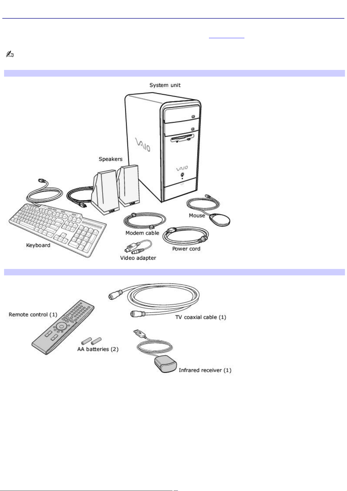
Your computer may not be supplied with all of the accessories shown, depending on the system configuration purchased.
For details on the accessories supplied with your computer, see the online Specifications sheet.
Your VAIO® computer is not supplied with System or Application Recovery CDs. Use the VAIO Recovery utility to recover
your computer's operating system and preinstalled software.
Computer and supplied accessories
Giga Pocket Personal Video Recorder accessories (for selected models)
Manuals
VAIO® Computer Quick Start — Provides basic information on setting up and registering your computer. The Quick
Start also provides resources for technical support, safety guidelines, and owner's information.
Online Documentation
VAIO® Computer User Guide — Contains information on the hardware and preinstalled software applications
included with your system.
To access the online manual:
1.
Click Start in the Windows taskbar, then click Help and Support.
Page 3

2.
From the VAIO Help And Support Center menu, click VAIO User Guide.
Specifications — This online specification sheet describes the hardware and software configuration of your VAIO
computer.To access this online information, go to the Specifications sheet.
VAIO Software — Provides specific information on the preinstalled software on your computer.
To access this online software information:
1.
Click Start in the Windows® taskbar
2.
Click Welcome to VAIO Life.
Hard Disk Drive Recovery
Your computer is equipped with a utility program that recovers your computer's operating system and preinstalled
software.
For more information about hard disk drive recovery
1.
Click Start in the Windows® taskbar, then click Help and Support.
2.
From the VAIO Help And Support Center menu, click VAIO Recovery Options.
Other
A Software Library, containing the Microsoft software and Sony end-user license agreements.
Page 4

Planning an Ergonomic Work Space
Before you set up your new computer, find the best location for your new computer and plan your work space. There are
several ergonomic factors to consider when you arrange your work space:
Stable work surface — Use a stable work surface large enough to support the computer and other peripheral
equipment.
Ventilation — Leave at least eight inches of space on the left and back sides of your computer to enable proper
ventilation.
Placement of the keyboard, mouse, and other input devices — Place your keyboard, mouse, and other input
devices so that your arms and hands are in a relaxed, comfortable position. The keyboard should be directly in front
of you. Adjust the level of the keyboard so that your lower arms are parallel to the floor. Keep your wrists in a
relaxed position when you are using the keyboard — not angled up or down. Use the palmrest only briefly, for
resting. While typing, never use the palmrest or rest your hands on the table. Position the mouse at the same level
as the keyboard. Hold the mouse with a relaxed hand, and use your whole arm to move it. Take breaks during
sessions with your computer. Excessive use of the mouse or a joystick may strain muscles or tendons.
Furniture and posture — Sit in a chair with good back support and armrests. Adjust the level of the chair so your
feet are flat on the floor. A footrest may make you more comfortable. Sit with relaxed, upright posture — avoid
slouching forward or leaning far backward.
Viewing angle of the display — Position the display 18 to 26 inches directly in front of you, with the top of the
screen at or a little below eye level. Use the display's tilting feature to find the best position. You can reduce eye
strain and muscle fatigue by placing the display in the proper position.
Lighting — Choose a location where windows and lights do not create glare and reflection on the display. Use
indirect lighting to avoid bright spots on the display. You can also purchase accessories for your display that help
reduce glare. Proper lighting adds to your comfort and work effectiveness.
Page 5

Locating Controls And Ports
This section is intended to familiarize you with the controls, ports and jacks on your computer. Your computer may not be
equipped with all of these hardware features, and the location of the controls, ports, and jacks may vary from the
illustrations shown in this section. To view the specific connection capabilities for your system, see the online specifications
sheet.
About the Front Panel
About the Back Panel
About the Remote Control
About the Keyboard
Page 6
About the Front Panel
The front panel of your VAIO® computer enables access to the optical and floppy disk drives. On certain models, the front
panel also provides access to a Memory Stick® media slot, Giga Pocket Personal Video Recorder features, SmartMedia ,
CompactFlash®/Microdrive media card slot, Universal Serial Bus (USB) and i.LINK® ports that enable you to connect
compatible peripheral devices. System configuration may vary, depending on the model purchased. See the online
specifications sheet for details.
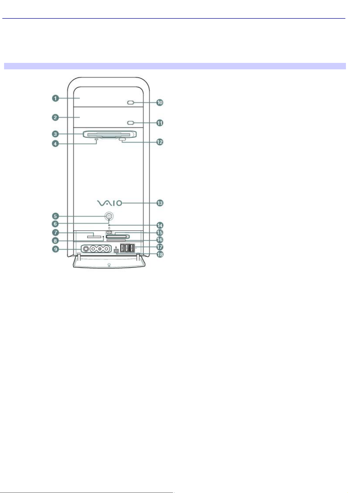
Front panel
1 Optical drive 1
See the online specifications sheet for optical drive information.
2 Optical drive 2
See the online specifications sheet for optical drive information.
3 Floppy disk drive
Reads and writes data from and to a 3.5-inch floppy disk.
4 Floppy disk drive access indicator
Light is green while reading and writing data from and to a floppy disk.
5 Power button
The power button turns the computer on/off.
Page 7

6 Standby indicator
Light is amber when the computer is in Stand by mode.
7 Memory Stick media slot and access indicator1
Reads and writes data from and to a Memory Stick® media. The access indicator is amber when reading or writing data to a
Memory Stick media.
8 Media access indicator2
Light is amber when reading or writing data.
9 S-video In jack1
Connection for an S-video cable (optional).
Composite video In jack1
Connection for a video cable (optional).
Composite audio L In jack1
Connection for an audio cable (optional).
Composite audio R In jack1
Connection for an audio cable (optional).
10 Optical drive 1 eject button
Ejects a disc from Optical drive 1.
11 Optical drive 2 eject button
Ejects a disc from Optical drive 2.
12 Floppy disk eject button
Ejects a floppy disk.
13 Power indicator (VAIO)
Light is blue when the computer is on. The light turns off when the computer is in Standby mode or turned off.
14 Hard disk drive and optical disc drive access indicator
Light is amber while reading and writing data.
Page 8

15 CompactFlash/Microdrive media card slot1
Reads and writes data from and to CompactFlash or Microdrive media.
16 SmartMedia card slot1
Reads and writes data from and to a SmartMedia media.
17 Universal Serial Bus (USB 2.0) ports3
Connections for compatible high/full/low-speed USB devices.
18 i.LINK 4-pin S400 port (IEEE 1394)
Connection for a compatible digital device.
1
Not available on all models. See your online Specifications s heet for details .
2
O n models equipped with this hardware configuration, the media access indic ator light is amber when reading or writing data to the SmartMedia or
C ompactFlash®/Microdrive slots.
3
T he number of U SB ports may vary depending on the model purc has ed.
For your convenience, your computer includes USB and i.LINK ports on both the front and back panels. The 4-pin
i.LINK port is located on the front panel and the 6-pin i.LINK port is located on the back.
Additional information
Your computer is equipped with two optical disc drives that have a drive eject button on the drive door.
After pushing the eject button, wait for the drive to stop reading the CD. It may take a few moments for the drive
tray to eject.
Gently push the drive tray in, when closing the optical drive door. Do not force the door or handle roughly.
After closing the drive door, wait a few moments for the drive to begin reading the CD.
Page 9
About the Back Panel
The back panel of your computer contains the ports for supplied and optional accessories. The icons on the back panel
locate and identify the ports and jacks on your computer.
Your configuration may vary based on the system you purchased.
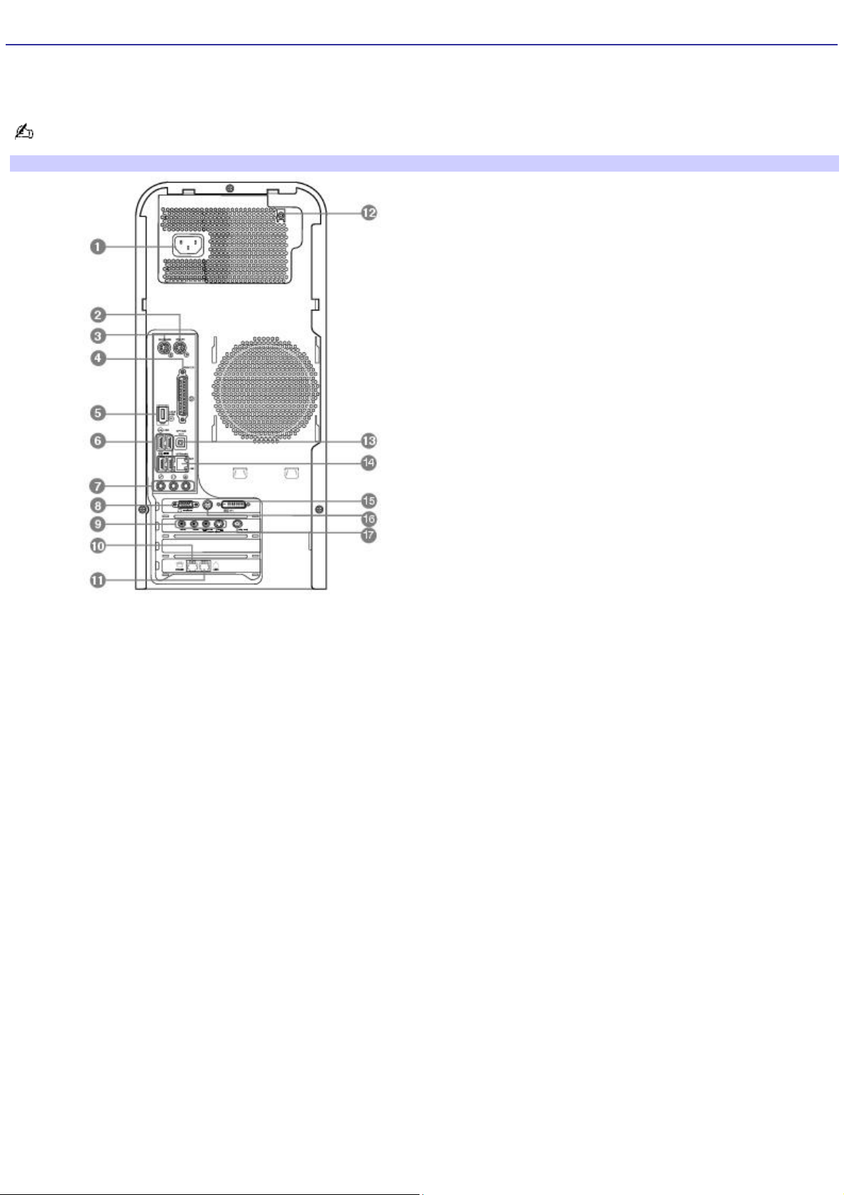
Back panel
1 AC Input port
Connection for the supplied power cord.
2 Mouse port
Connection for a PS/2® mouse.
3 Keyboard port
Connection for a PS/2® keyboard.
4 Printer port
Connection for a parallel device, such as a printer or scanner.
5 i.LINK 6-pin S400 port (IEEE 1394)
Connection for a compatible digital device.
6 Universal Serial Bus (USB 2.0) ports (4)
Connections for compatible high/full/low-speed USB devices.
Page 10

7 Microphone jack
Connection for a microphone (optional).
Headphones jack
Connection for the supplied speakers or optional headphones.
Line In jack
Connection for an audio device.
8 Monitor port
Connection for a standard display.
9 Composite audio R In jack1
Connection for an audio or stereo dubbing cable (optional).
Composite audio L In jack1
Connection for an audio or stereo dubbing cable (optional).
Composite video In jack1
Connection for a digital video or stereo A/V dubbing cable (optional).
S-video In jack1
Connection for an S-video cable (optional).
10 Telephone jack
Connection for a telephone cable (optional) to the computer.
11 Modem line jack
Connection for the modem cable to the wall jack.
12 Speaker DC Out jack2
Connection for the speaker power cable.
13 S/P DIF Optical Out port
Connection for a digital audio or optical device.
Page 11
14 Ethernet port
Connection for a 10BASE-T/100BASE-TX Ethernet interface.
(The port marked with (Network) is for LAN connections only.)
15 Monitor (DVI) port
Connection for a DVI monitor.
16 TV Out (S-Video/video) jack
Connection for an S-video cable (optional).
17 VHF/UHF port1
Connection for a coaxial cable (supplied).
1
Not available on all models. See your online Specifications s heet for details .
2
Y our c omputer is s upplied with speakers that use A C power. The speaker DC out jac k provides power for s tereo s peakers equipped with a DC power c able,
which can be purc hased separately.
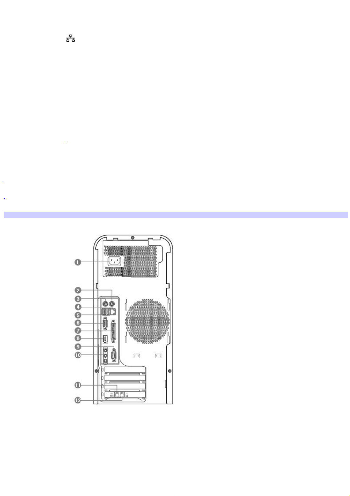
Back panel (PCV-RS410 series model)
1 AC Input port
Connection for the supplied power cord.
2 Mouse port
Page 12

Connection for a PS/2® mouse.
3 Keyboard port
Connection for a PS/2® keyboard.
4 Ethernet port
Connection for a 10BASE-T/100BASE-TX Ethernet interface.
(The port marked with (Network) is for LAN connections only.)
5 Universal Serial Bus (USB 2.0) ports (2)
Connections for compatible high/full/low-speed USB devices.
6 Monitor port
Connection for a display.
7 Printer port
Connection for a parallel device, such as a printer or scanner.
8 i.LINK 6-pin S400 port (IEEE 1394)
Connection for a compatible digital device.
9 Serial port
Connection for a compatible serial device.
10 Headphones jack
Connection for the supplied speakers or optional headphones.
Line In jack
Connection for an audio device.
Microphone jack
Connection for a microphone (optional).
11 Telephone jack
Connection for a telephone cable (optional) to the computer.
Page 13

12 Modem line jack
Connection for the modem cable to the wall jack.
i.LINK is a trademark of Sony used only to designate that a product contains an IEEE 1394 connection. The i.LINK
connection may vary, depending on the software applications, operating system, and compatible i.LINK devices. All products
with an i.LINK connection may not communicate with each other.
Please refer to the documentation that came with your compatible i.LINK device for information on operating conditions and
proper connection. Before connecting compatible i.LINK devices to your system, such as an optical or hard disk drive,
confirm their operating system compatibility and required operating conditions.
Page 14
About the Remote Control
Giga Pocket Personal Video Recorder features are controlled with the remote control. The remote control can start and
stop video recording and playback, select channels, and set viewing preferences. This section describes the basic functions
of your remote control.
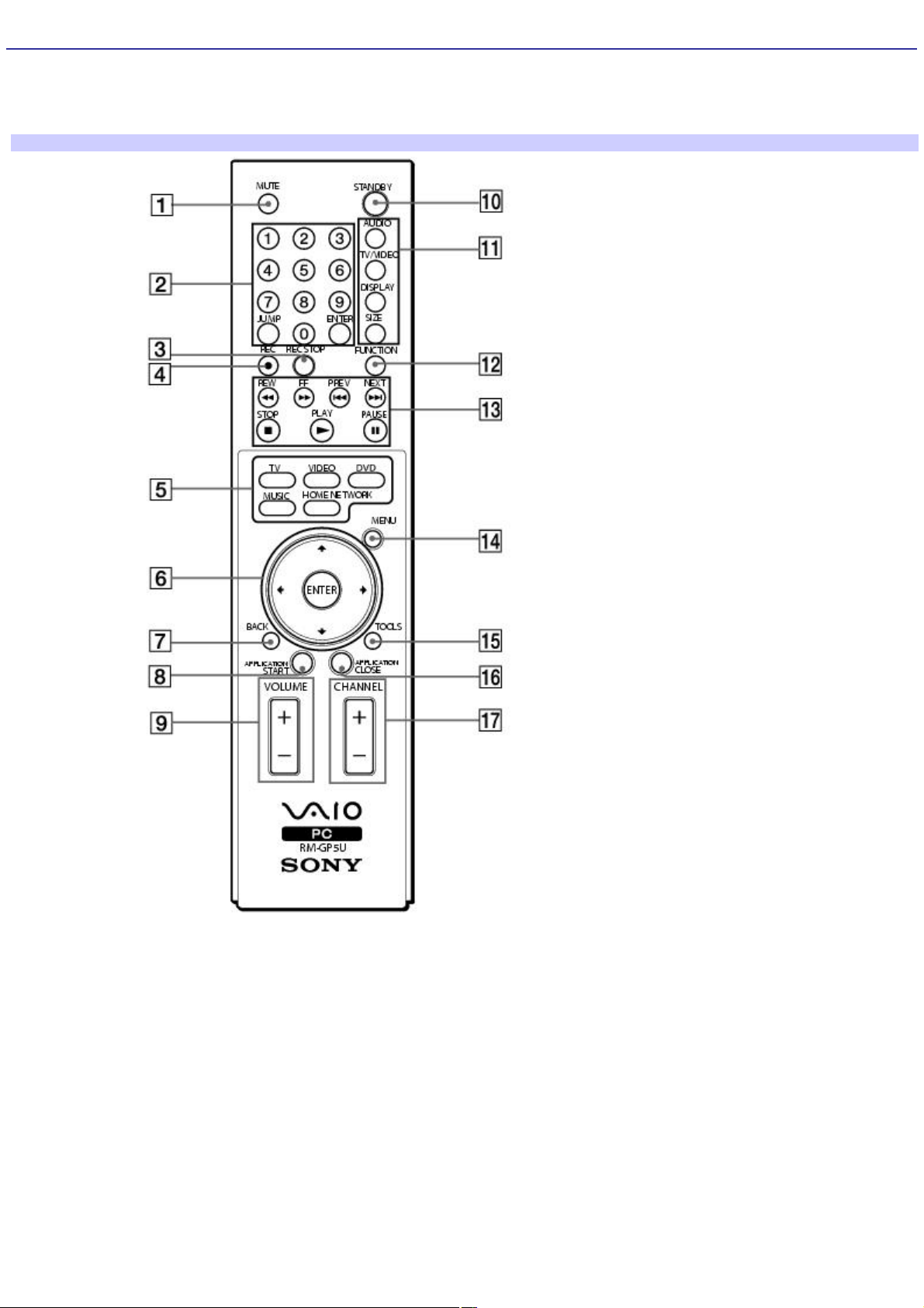
Remote control (for m odels equipped with Giga Pocket features)
1 MUTE button
Press to turn off the sound. Press again to restore the sound.
2 Channel number buttons (0 - 9)
Press to select specific channels.
(Press the ENTER button to activate channel selection.)
JUMP button
Press to go to the previous channel. Press again to return to the current channel.
Page 15

ENTER button
Press to activate channel selection. See Channel number buttons.
3 REC STOP button
Press to stop recording.
(Note: The REC STOP function is available for Giga Pocket software only.)
4 REC button
Press to begin recording.
(Note: The REC function is available for Giga Pocket software only.)
5 TV button
Press to change from the on-screen image to the TV/Recording deck.
VIDEO button
Press to change to the external video equipment, such as your VCR.
(Note: You cannot change the input source while recording.)
DVD button
Press to change to an external DVD device, such as a DVD player.
MUSIC button
Press to launch the SonicStage software.
HOME NETWORK button
Press to launch the VAIO Media.
6 Direction and ENTER buttons
Press a direction arrow to navigate. Press ENTER to select.
7 BACK button
Press to return to the previous screen.
(Note: This function is not available for Giga Pocket software.)
Page 16

8 APPLICATION START button
Press to launch the Giga Pocket software.
9 VOLUME button
Press to raise or lower the volume.
10 STANDBY button
Press to place the system into Stand by mode.
(Note: You cannot place the computer into Stand by mode when certain Giga Pocket functions are running.)
11 AUDIO button
Press to view available sound mode options on the monitor/display.
TV/VIDEO button
Press to change the on-screen image from the TV/Recording deck to external video equipment, such as your VCR.
(Note: You cannot change the input source while recording.)
DISPLAY button
During DVD playback in full screen mode, press to show the settings window. When using Giga Pocket software, press to
display the TV/Recording deck and playback deck screens. Press again to hide these views.
SIZE button
Press to view the current software in full-screen size. Press again to return the view to its original size.
12 FUNCTION button
When Giga Pocket software is selected with the MENU button, press to switch from the TV/recording deck to the playback
deck.
When using SonicStage software, press to change from the music drive (hard disk drive) to the CD.
13 REW and FF buttons
Press to rewind or fast-forward.
PREV and NEXT buttons
Press to move back to the previous screen or forward to the next screen.
Page 17
STOP button
Press to stop playback.
PLAY button
Press to begin playback.
PAUSE button
Press to pause playback.
14 MENU button
Press to view a shortcut menu of available software applications. Press again to hide this menu.
(Note: For Giga Pocket software, the Select Video Capsules window displays. Press the button again to hide this window.)
15 TOOLS button
The function of this button may vary between DVD media. See the DVD player software instructions for details.
16 APPLICATION CLOSE button
Press to close the Giga Pocket software.
17 CHANNEL button
Press to change channels automatically (no number input required).
(Note: This function is available for Giga Pocket software only.)
For more details about the function buttons on your remote control, see the Giga Pocket Help.
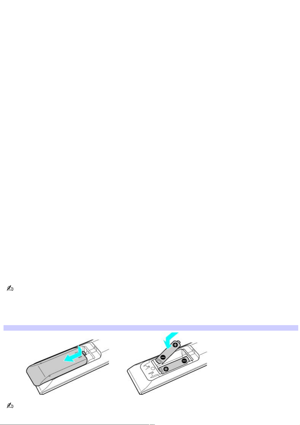
To set up the remote control
Insert two AA batteries (supplied) into the remote control as shown.
Inserting batteries into the remote control
If your remote control does not operate properly, the batteries may need to be replaced. When your remote control is
not being used for extended periods of time, remove the batteries to avoid possible damage from battery leakage.
Page 18

Page 19
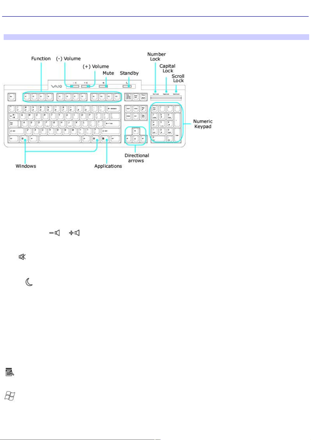
About the Keyboard
Your VAIO® keyboard uses a standard key arrangement with additional keys that perform specific functions.
VAIO Keyboard
KEY DESCRIPTION
Function The 12 function keys along the top of the keyboard are used to perform certain tasks. The task
associated with each function key may vary from one application to the next.
Volume Control Press a button to increase (+) or decrease (-) the volume of the speakers.
Mute Press the button to turn off the speaker sound. Press the Mute button again to restore sound.
Standby Press the button to place the computer in Standby mode. Press the Power button or any key
briefly, to resume normal operation.
Numeric keypad Use the numeric keypad area to type numbers or to perform basic math calculations. Press the
Num Lock key to activate the numeric keypad. (The Num Lock indicator lights.) Press the Num Lock key again to deactivate
the numeric keypad.
Directional Arrows The Up, Down, Left, and Right arrow keys move the pointer on the screen.
Applications
The Applications key displays a shortcut menu in certain software applications. Pressing this key
is equivalent to clicking the right mouse button.
Windows
The key with the Microsoft® Windows® logo, displays the Start menu. Pressing this key is
equivalent to clicking Start on the taskbar.
INDICATORS FUNCTION
Num Lock The Num Lock indicator lights when the numeric keypad is activated. When the indicator is off, the directional
arrow and correction keys on the numeric keypad area are active.
Page 20

Caps Lock The Caps Lock indicator lights up to advise you that the keyboard is set to type letters in uppercase. When
the indicator is off, the letters appear in lower case as you type.
Scroll Lock The Scroll Lock indicator lights up to advise you that your screen's scrolling pattern has changed. When the
indicator is off, the screen scrolls normally. This function is not available with all software applications.
Page 21

Setting Up Your Computer
Your computer may not be equipped with all of the hardware features described in the section. The location of the controls,
ports, and jacks may vary from the illustrations shown. See the online specifications sheet for your system's specific
hardware configuration.
Connecting a Display (Monitor)
Connecting the Speakers
Connecting the Keyboard and Mouse
Connecting the Telephone and Modem Cables
Connecting the Power Cords
Turning On your Computer
Registering your Computer
Page 22
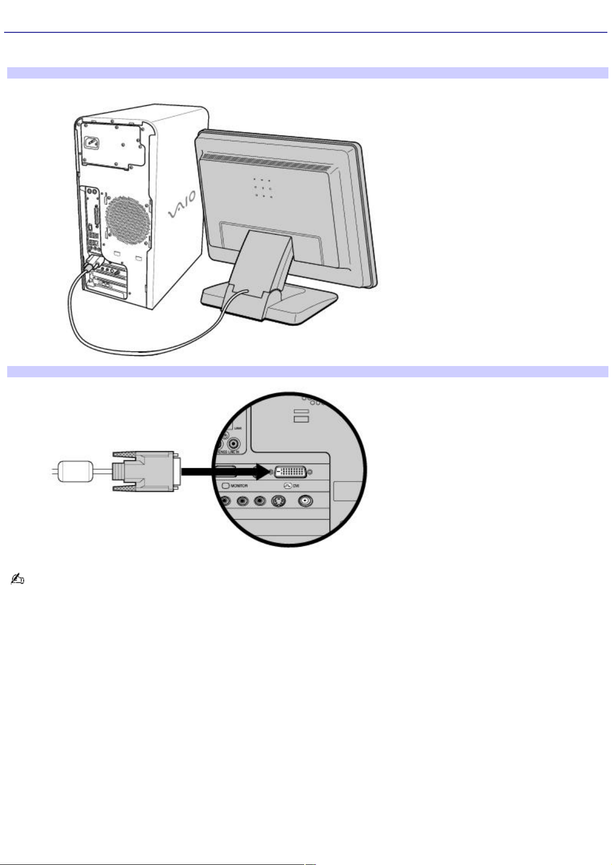
Connecting a Display (Monitor)
Plug the display's cable into the appropriate monitor port. If necessary, plug the display's cable into the back of the display.
To connect a display
To connect a DVI display
Install your equipment so that you can easily reach the power outlet in the event of an emergency.
Page 23
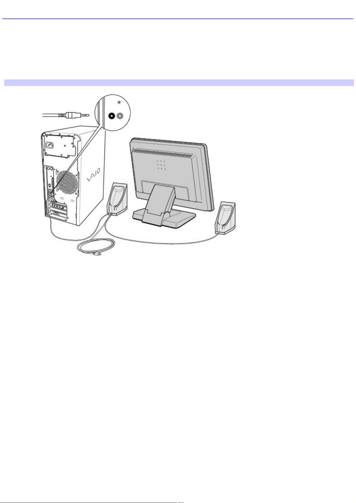
Connecting the Speakers
The right and left speakers are attached. The right speaker has a speaker wire with a jack connector and an AC power cord
that supplies power to both speakers.
1.
From the right speaker, plug the jack connector into the Headphones jack located on the back panel of your
computer.
2.
From the right speaker, insert the AC adapter plug into a grounded AC wall outlet or surge suppressor.
To connect the speakers
Page 24
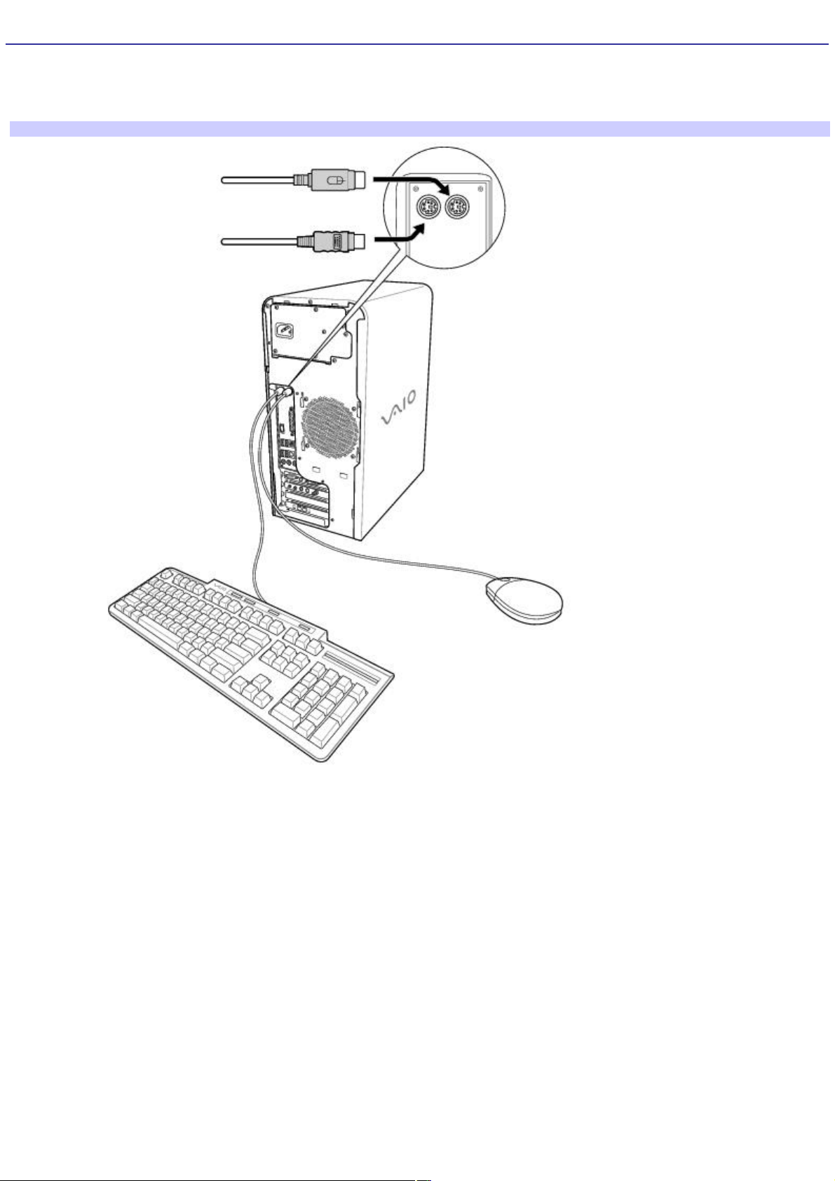
Connecting the Keyboard and Mouse
1.
Plug the keyboard cable into the keyboard port on the back of the computer.
2.
Plug the mouse cable into the mouse port on the back of the computer.
To connect the keyboard and mouse
To use an optical mouse
An optical mouse requires an ideal surface in order to provide proper pointing and tracking.
Use surfaces such as plain paper, card stock, or fabric that have minimal repetitive patterning.
Avoid surfaces such as mirrors, smooth glass, or magazines that have half- tone printing.
Page 25
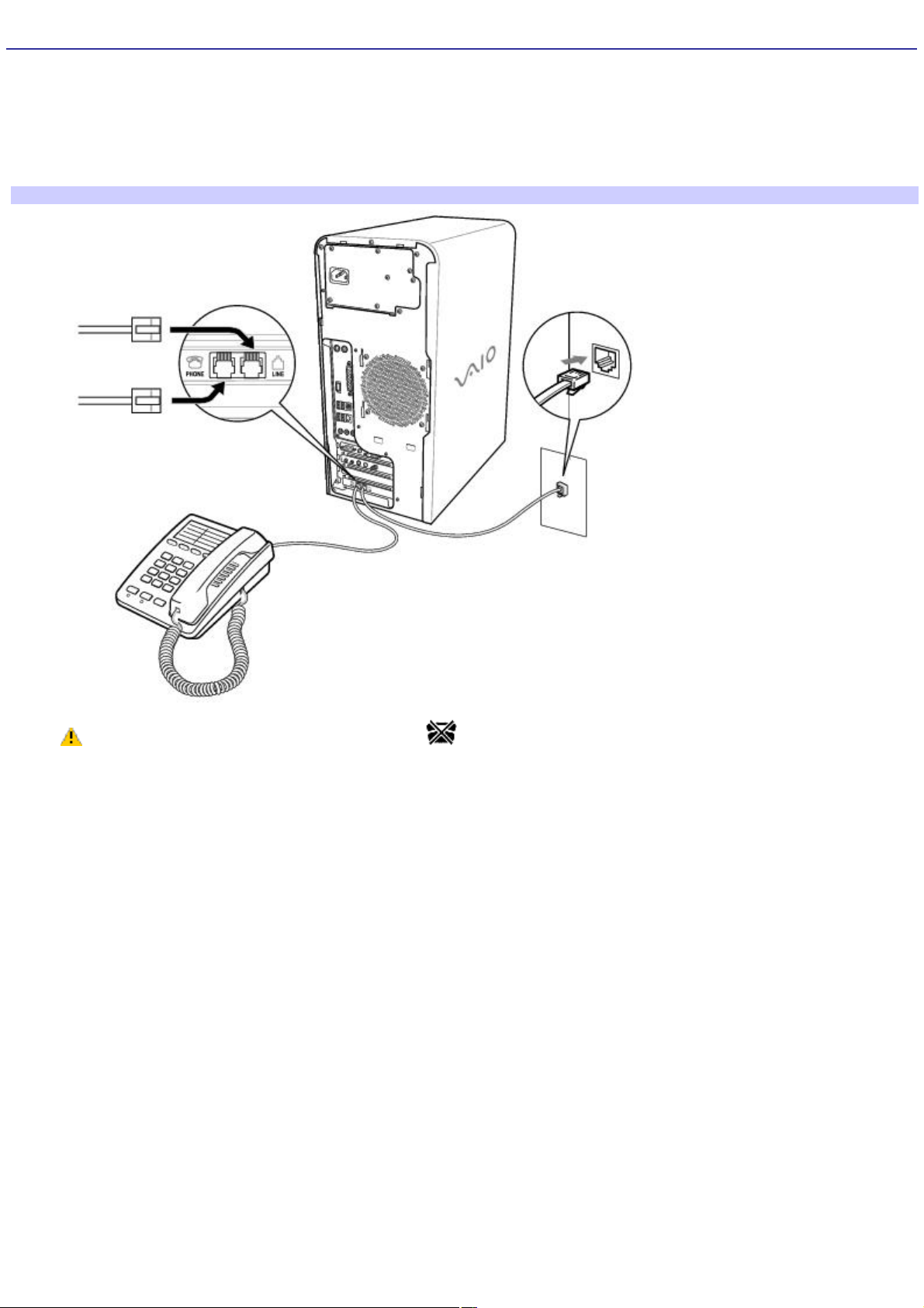
Connecting the Telephone and Modem Cables
1.
Unplug your telephone from the wall jack and plug its cable into the telephone jack located on the back panel of
your computer.
2.
Plug the modem cable (supplied) into the modem line jack located on the back panel of your computer
3.
Plug the other end of the modem cable into the wall jack.
To connect the telephone and modem cables
Your computer has a protective sticker covering the Ethernet port located on the rear panel.
Connect only 10BASE-T and 100BASE-TX cables to the Ethernet port. Using other cables or a telephone cable
may result in an electric current overload that can cause a malfunction, excessive heat, or fire in the Ethernet
port. For help on connecting to a network, see your network administrator.
Page 26
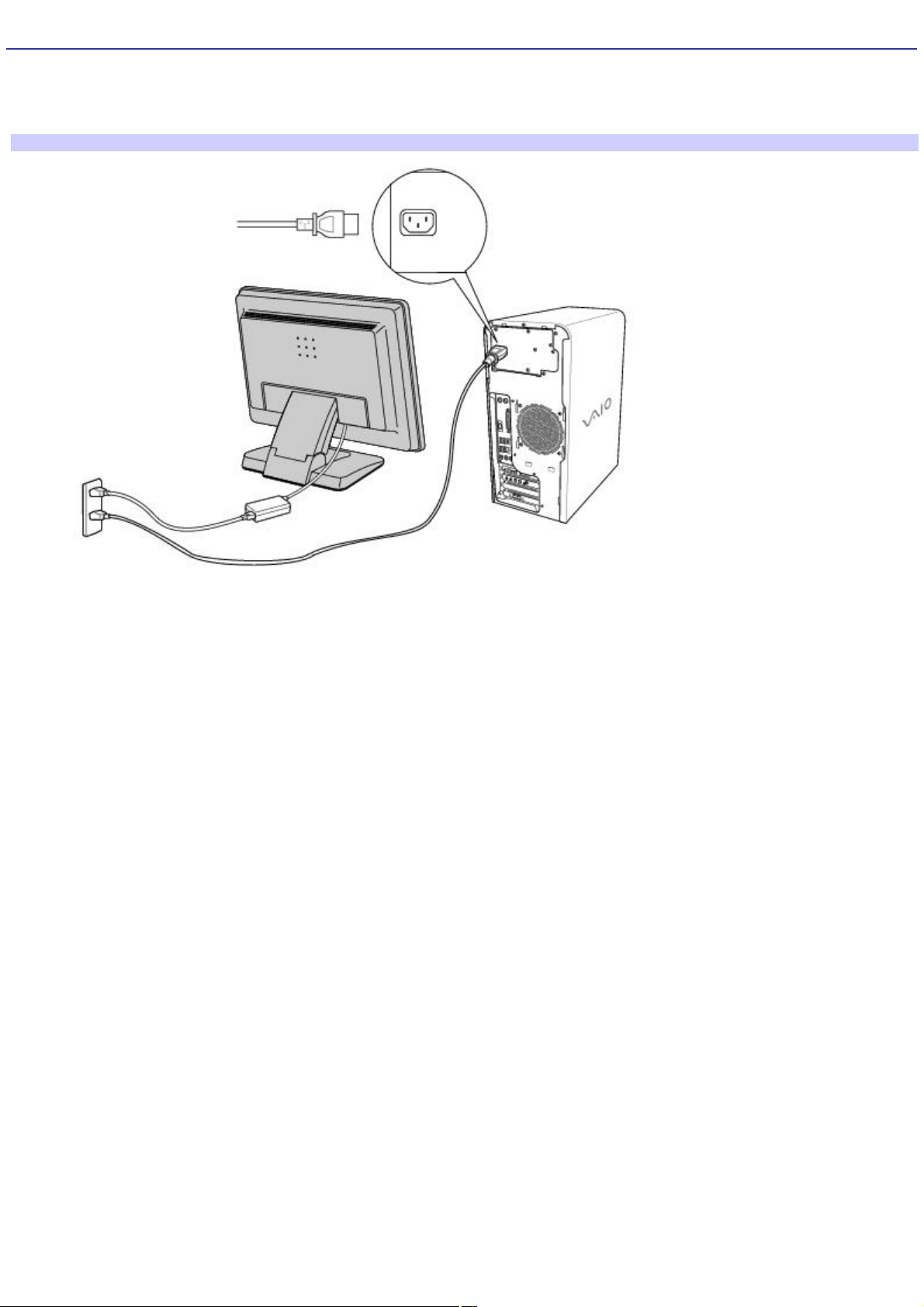
Connecting the Power Cords
1.
Plug the power cord into the AC Input port, located on the back panel of the computer.
2.
Plug both the display and computer power cords into a grounded AC wall outlet or a power strip.
To connect the power cords
Page 27
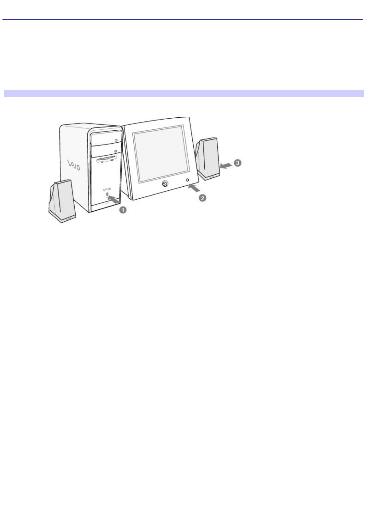
Turning On your Computer
When you start your system for the first time, your computer may detect new equipment and display a dialog box that
prompts you to restart your computer. Respond to this prompt immediately.
1.
Press the power button on the computer to turn on the power.
2.
Press the power button on the display to turn on the power.
3.
Press the power button, located on the side of the right speaker, to turn on the power.
To turn on your computer
Page 28

Registering your Computer
Take advantage of Sony's commitment to quality customer support and receive these benefits by registering your
computer:
Sony Customer Support — Communicate with a Support Representative to troubleshoot problems you may be
having with your computer.
Limited warranty — Protect your investment. See the Limited Warranty Card for more details.
You are prompted to register your computer the first time you turn on the unit. Follow the on-screen instructions to
complete the registration process. If you are not able to register your computer during the first session, you are provided
with additional registration opportunities later.
Page 29

Giga Pocket Personal Video Recorder
Giga Pocket Personal Video Recorder is a suite of interactive Sony audio and video components that are designed to
create, capture, and play back video files derived from television and your personal videos.1
Giga Pocket Personal Video Recorder hardware and software applications are not available on all VAIO® computers.
See your computer's online specification sheet for details on your system configuration.
About Giga Pocket Personal Video Recorder
Setting Up Giga Pocket Personal Video Recorder
Setting Up Giga Pocket Software
Giga Pocket
Timer Recording Wizard
Timer Recording Manager
Giga Pocket Explorer
CLIÉ Converter
Glossary
Internet Electronic Program Guide Service
1
U nauthorized duplication of audio or video files is a violation of applicable laws.
Page 30
 Loading...