

Sony PCV-E205, PCV-E201 Reference Manual


Notice to Users
© 1998 Sony Electronics Inc. All rights
reserved. This manual and the software
described herein, in whole or in part, may not
be reproduced, translated, or reduced to any
machine-readable form without prior written
approval.
SONY ELECTRONICS INC. PROVIDES NO
WARRANTY WITH REGARD TO THIS
MANUAL, THE SOFTWARE, OR OTHER
INFORMATION CONTAINED HEREIN
AND HEREBY EXPRESSLY DISCLAIMS
ANY IMPLIED WARRANTIES OF
MERCHANTABILITY OR FITNESS FOR
ANY PARTICULAR PURPOSE WITH
REGARD TO THIS MANUAL, THE
SOFTWARE, OR SUCH OTHER
INFORMATION. IN NO EVENT SHALL
SONY ELECTRONICS INC. BE LIABLE
FOR ANY INCIDENTAL,
CONSEQUENTIAL, OR SPECIAL
DAMAGES, WHETHER BASED ON TORT,
CONTRACT, OR OTHERWISE, ARISING
OUT OF OR IN CONNECTION WITH THIS
MANUAL, THE SOFTWARE, OR OTHER
INFORMATION CONTAINED HEREIN OR
THE USE THEREOF.
Sony Electronics Inc. reserves the right to
make any modification to this manual or the
information contained herein at any time
without notice. The software described
herein may also be governed by the terms of
a separate user license agreement.
S on y VA IO , a nd t he VAI O l og o a re
trademarks of Sony. Microsoft, Windows,
and the Windows 98 logo are registered
trademarks of Microsoft Corporation. Intel,
Pentium, and Celeron are trademarks of Intel
Corporation. K56flex is a trademark of
Lucent Technologies Inc. and Rockwell
International. All other trademarks are
trademarks of their respective owners.
Safety Information
Owner’s Record
The model number and serial number are
located on the back of your VAIO computer.
Record the serial number in the space
provided here. Refer to the model and serial
number when you call your Sony Service
Center.
Model Number: PCV-E201/PCV-E203/
PCV-E205
Serial Number:________________________
WAR N I N G
❑ To prevent fire or shock hazard, do
not expose your VAIO computer to
rain or moisture.
❑ Never install modem or telephone
wiring during a lightning storm.
❑ Never install telephone jacks in wet
locations unless the jack is specifically
designed for wet locations
❑ Never touch uninsulated telephone
wire or terminals unless the telephone
line has been disconnected at the
network interface.
❑ Use caution when installing or
modifying telephone lines.
❑ Avoid using the modem during an
electrical storm.
❑ Do not use the modem or a telephone
to report a gas leak in the vicinity of
the leak.
!
The use of optical instruments
with this product will increase eye
hazard.

Regulatory Information
Declaration of Conformity
Trade Name: SONY
Model No.: PCV-E201/PCV-E203/
PCV-E205
Responsible Party:
Sony Electronics Inc.
Address:
1 Sony Drive
Park Ridge, NJ 07656
Telephone No: 201-930-6970
This device complies with Part 15 of
FCC Rules. Operation is subject to
the two following conditions: (1)
This device may not cause harmful
interference, and (2) this device
must accept any interference
received, including interference that
may cause undesired operation.
This equipment has been tested and found
to comply with the limits for a Class B
digital device, pursuant to Part 15 of the
Rules. These limits are designed to
provide reasonable protection against
harmful interference in a residential
installation. This equipment generates,
uses, and can radiate radio frequency
energy and, if not installed and used in
accordance with the instructions, may
cause harmful interference to radio
communications. However, there is no
guarantee that interference will not occur
in a particular installation. If this
equipment does cause harmful
interference to radio or television
reception, which can be determined by
turning the equipment off and on, the user
is encouraged to try to correct the
interference by one or more of the
following measures:
❑ Reorient or relocate the receiving
antenna.
❑ Increase the separation between the
equipment and the receiver.
❑ Connect the equipment into an
outlet on a circuit different from
that to which the receiver is
connected.
❑ Consult the dealer or an
experienced radio/TV technician
for help.
You are cautioned that any changes or
modifications not expressly approved in
this manual could void your authority to
operate this equipment.
Only peripherals (computer input/output
devices, terminals, printers, etc.) that
comply with FCC Class B limits may be
attached to this computer product.
Operation with non-compliant peripherals
is likely to result in interference to radio
and television reception.
All cables used to connect peripherals
must be shielded and grounded.
Operation with cables, connected to
peripherals, that are not shielded and
grounded, may result in interference to
radio and television reception.

FCC Part 68
This equipment complies with Part 68 of the
FCC rules. The ringer equivalence number
(REN) and the FCC registration number are
printed on the modem board. If requested,
this information must be supplied to the
telephone company.
The REN is used to determine the quantity of
devices which may be connected to the
phone line. Excessive REN's on the telephone
line may result in the devices not ringing in
response to an incoming call. In most, but not
all areas, the sum of the REN's should not
exceed five (5.0). To be certain of the number
of devices that may be connected to the line,
as determined by the total REN's, contact the
telephone company to determine the
maximum REN for the calling area.
This modem uses the USOC RJ-11 telephone
jack.
If this equipment causes harm to the
telephone network, the telephone company
will, when practical, notify you in advance
that temporary discontinuance of service
may be required. If advance notice isn't
practical, the telephone company will notify
you as soon as possible. Also, you will be
advised of your right to file a complaint with
the FCC if you believe it is necessary.
The telephone company may make changes
in its facilities, equipment, operations or
procedures that could affect the operations of
the equipment. If this happens, the telephone
company will notify you in advance, in order
for you to make the necessary modifications
in order to maintain uninterrupted service.
If trouble is experienced with this modem,
for repair or warranty information, please
contact 1-888-4SONY-PC, or write to the
Sony Customer Information Center, One
Sony Drive, Park Ridge, NJ 07656.
This equipment cannot be used on
telephone-company-provided coin service.
Connection to Party Line Service is subject to
state tariffs.
Repair of the modem should be made only
by a Sony Service Center or Sony authorized
agent. For the Sony Service Center nearest
you, call 1-800-222-SONY (1-800-222-7669).
Telephone Consumer Protection Act of 1991
The Telephone Consumer Protection Act of
1991 makes it unlawful for any person to use
a computer or other electronic device to send
any message via a telephone facsimile
machine unless such message clearly
contains, in a margin at the top or bottom of
each transmitted page or on the first page of
the transmission, the date and time it is sent
and an identification of the business, other
entity, or individual sending the message,
and the telephone number of the sending
machine or such business, other entity, or
individual.
In order to program this information into
your facsimile, see your fax software
documentation.
✍
You are cautioned that any changes or
modifications not expressly approved in
this manual could void your authority to
operate this equipment.

Contents
Notice to Users .................................................................................... ii
Safety Information .............................................................................. ii
Regulatory Information..................................................................... iii
FCC Part 68 ......................................................................................... iv
Telephone Consumer Protection Act of 1991................................. iv
Chapter 1 — Identifying Components
Front View ....................................................................................... 2
Drives ...................................................................................................3
Buttons and Switches .........................................................................4
Indicators ..............................................................................................5
Rear View ......................................................................................... 6
Icons .....................................................................................................7
I/O Connectors ....................................................................................9
Expansion Slots ..................................................................................14
Chapter 2 — Configuring Your System
Accessing the BIOS Setup Utility ................................................ 16
Changing the Display's Power-management Settings ............. 17
Configuring the System Board .................................................... 18
Chapter 3 — Removing, Installing and Reinstalling
Components
Removing the Side Panel .............................................................. 22
Removing the Bottom Panel......................................................... 23
Removing the Front Panel ............................................................ 24
Reinstalling the Front Panel ......................................................... 25
Reinstalling the Bottom Panel ...................................................... 26
v

vi
VAIO MicroTower System Reference
Reinstalling the Side Panel............................................................27
Installing an Add-In Card .............................................................28
Removing an Add-in Card............................................................29
Replacing the Lithium Battery .....................................................31
Installing System Memory ...........................................................34
Removing a Memory Module .....................................................37
Detaching the Diskette Drive .......................................................39
Removing a Slot Cover ..................................................................40
Covering an Open I/O Slot ..........................................................41
Chapter 4 — System Board
Connectors.......................................................................................44
Front Panel Header............................................................................44
Diskette Drive Connector ................................................................ 45
Memory Module (DIMM) Connectors ...........................................46
Slot Connectors...................................................................................47
IDE Connectors .................................................................................49
Power Connector ............................................................................... 50
Keyboard and Mouse Connectors ..................................................51
USB Connectors .................................................................................52
Serial, Printer and Monitor Connectors .........................................53
Fan Connectors ..................................................................................56
Game Connector.................................................................................57
Headphones, Line In, Mic Connectors............................................58
Ring Connector...................................................................................59
Modem In Connector ........................................................................60
CD In Connector ................................................................................61
TV Out Connector.............................................................................. 62
Configuration Jumpers .................................................................63
CPU Speed ..........................................................................................63
Clear Password and BIOS Recovery ...............................................64
Chapter 5 — TV-Out Paddle Card
Connectors .....................................................................................66
Chapter 6 — Fax/Modem Card
Connectors ......................................................................................68

Chapter 7 — BIOS Setup Options
Main Screen ................................................................................... 71
Advanced Screen .......................................................................... 76
Security Screen ............................................................................... 79
Power Screen .................................................................................. 80
Boot Screen ..................................................................................... 82
Exit Screen....................................................................................... 83
Chapter 8 — Miscellaneous Technical Information
About User and Supervisor Passwords ..................................... 86
Beep Code Error Messages .......................................................... 87
PCI Configuration Status And Error Messages ........................ 88
DMA Channel Assignments ....................................................... 90
IRQ Assignments ......................................................................... 91
System I/O Address Map ........................................................... 92
Memory Map ................................................................................. 94
Chapter 9 — Specifications
Processor ....................................................................................... 95
Memory Modules (DIMMs) ....................................................... 95
DIMM Configurations .................................................................. 96
L2 Cache ......................................................................................... 96
Graphics ........................................................................................ 96
Video ............................................................................................... 97
Audio .............................................................................................. 97
Communications .......................................................................... 97
I/O and Expansion Slots .............................................................. 97
Drives and Controllers ................................................................ 98
BIOS ............................................................................................... 98
Power Supply ................................................................................ 99
CPU Environment ........................................................................ 99
vii

viii

Chapter 1
Identifying Components
The following sections identify and describe each component that is
visible from the exterior of the VAIO MicroTower. Internal components
are identified in the appropriate section of this manual.
1
2
VAIO MicroTower System Reference
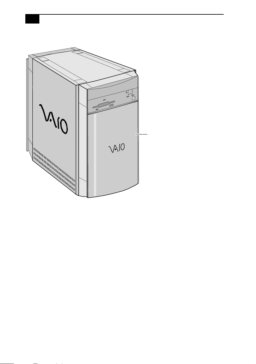
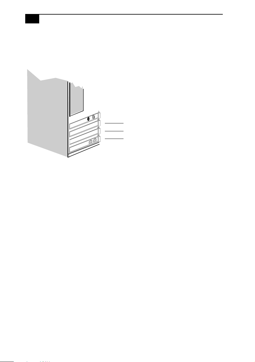
Front View
Front panel
OM04694X.VSD
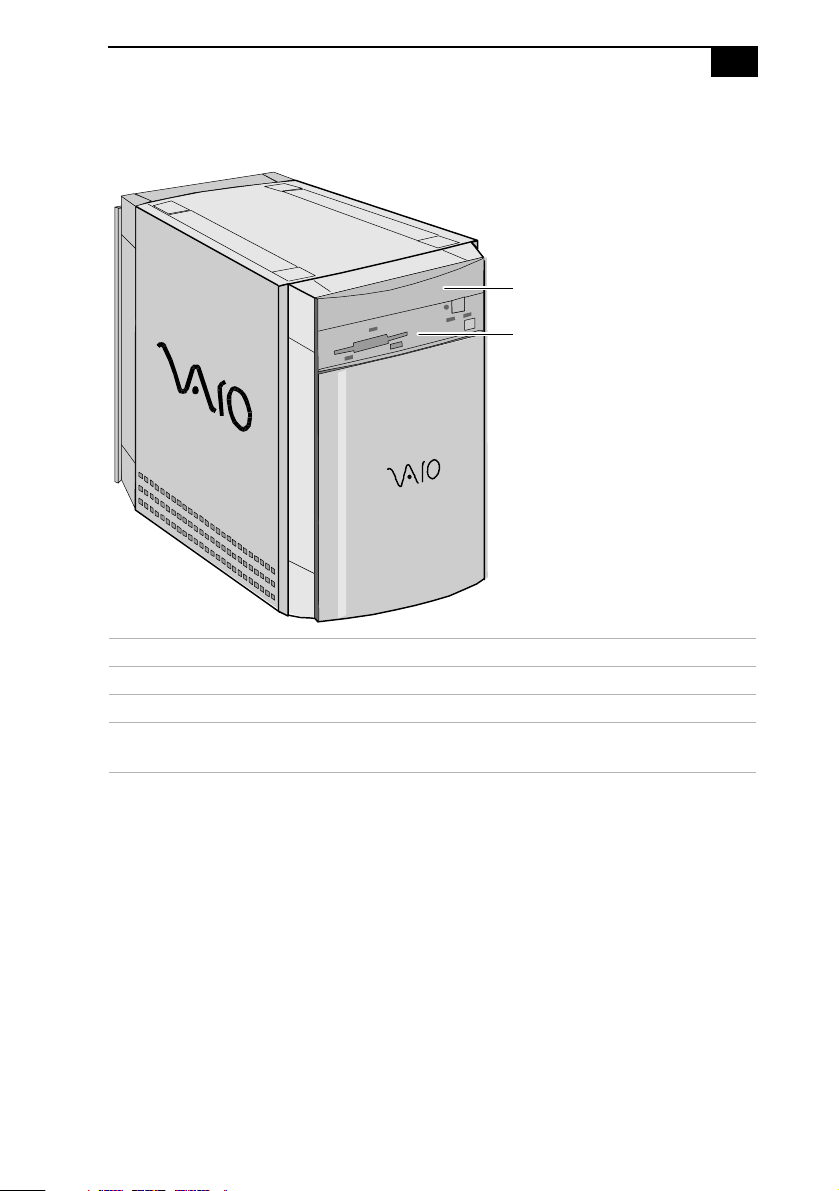
Drives
Identifying Components
CD-ROM drive (PCV-E201)
DVD-ROM drive (PCV-E203/PCV-E205)
Diskette drive
3
FNRTPNLA.VSD
Drive Description
Diskette drive 3.5-inch, 1.44 Mbyte.
CD-ROM drive (PCV-E201) 24X (maximum performance).
DVD-ROM drive
5X (maximum performance).
*
†
(PCV-E203/PCV-E205)
* Data on a CD-ROM disc is read at a variable transfer rate, ranging from 10X at the innermost track to 24X
at the outermost track (the data transfer standard 1X rate is 150 kbytes/s). The average data transfer ra te
is 17X (2550 kbytes/s).
† DVD-ROM drive also plays CD-ROM discs. Data on the DVD-ROM is read at a variable transfer rate, ranging
from 2X at the innermost track to 5X at the outermost track (the data transfer standard 1X rate is 1385
kbytes/s). The average data transfer rate is 3.4X (4709 kbytes/s). Data on a CD-ROM disc is read at a variable
transfer rate, ranging from 10X at the innermost track to 24X at the outermost track (the data transfer
standard 1X rate is 150 kybtes/s). The average data transfer rate is 17X (2250 kbytes/s).
4
VAIO MicroTower System Reference
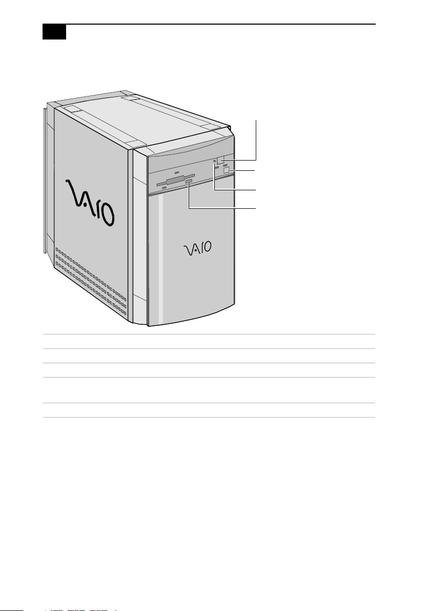
Buttons and Switches
CD-ROM drive disc eject button (PCV-E201)
DVD-ROM drive disc eject button (PCV-E203/PCV-E205)
Power on/off switch
Emergency-eject hole
Diskette eject button
FNRTPNLB.VSD
Button or switch Description
Power on/off switch Turns system power on and off.
Diskette eject button Ejects a diskette.
CD-ROM/DVD-ROM
disc eject button
Automatically opens and closes the CD-ROM or
DVD-ROM tray.
Emergency-eject hole Ejects a CD-ROM disc or DVD-ROM disc.
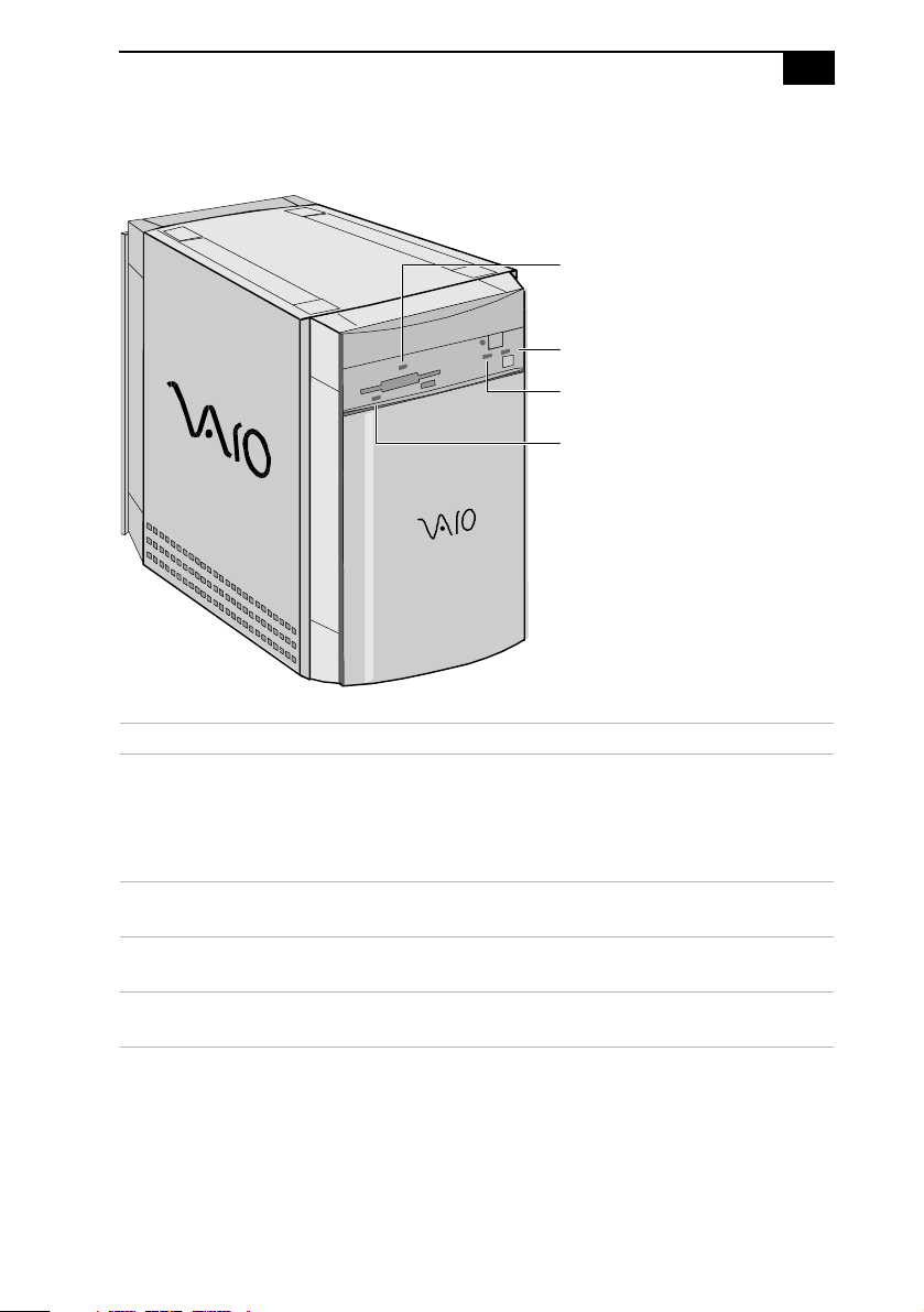
Indicators
Identifying Components
Drive access indicator for:
CD-ROM drive (PCV-E201)
DVD-ROM drive (PCV-E203/PCV-E205)
Power-on indicator
Hard disk drive access indicator
Diskette drive access indicator
5
FRNTPNLD.VSD
Indicator Description
Power-on indicator On (amber) indicates the computer is in
standby mode. On (green) indicates the
computer is out of standby mode, ready to
use. Off (no color) indicates the computer
is turned off.
Diskette drive access indicator On (green) indicates diskette drive
activity.
CD-ROM/DVD-ROM drive
access indicator
On (orange) indicates CD-ROM or DVDROM disc activity.
Hard disk drive access indicator On (orange) indicates hard disk drive
activity.
6
VAIO MicroTower System Reference
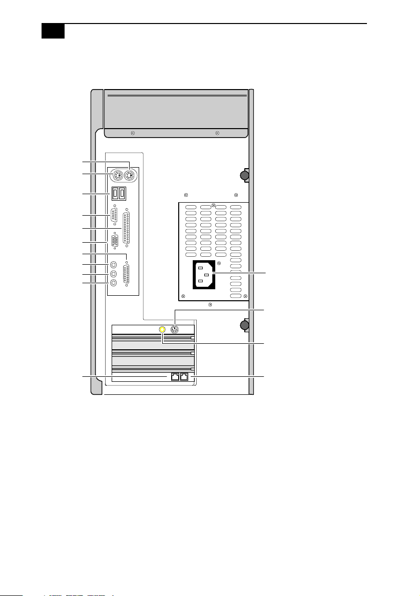
Rear View
Mouse
Keyboard
USB
Serial
Printer
Monitor
Game
Headphones
Line In
Mic
Power socket
S Video Out
(models PCV-E203/PCV-E205 only)
Line
Video Out
(models PCV-E203/PCV-E205 only)
Telephone
KY0001.VSD
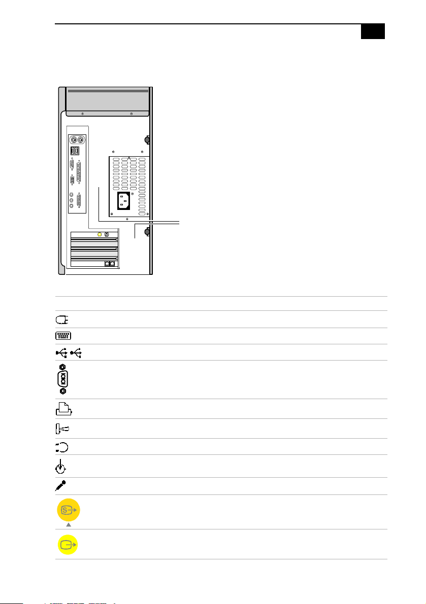
Icons
Icon Description
Mouse connector
Keyboard connector
Universal Serial Bus (USB) connectors
Serial port connector
Icon labels
Identifying Components
7
OM04692X.VSD
Printer port connector
Game/MIDI port connector
Headphones
Line In jack (audio)
Microphone jack
S Video Out jack
(models PCV-E203/PCV-E205 only)
Video Out jack
(models PCV-E203/PCV-E205 only)
8
VAIO MicroTower System Reference
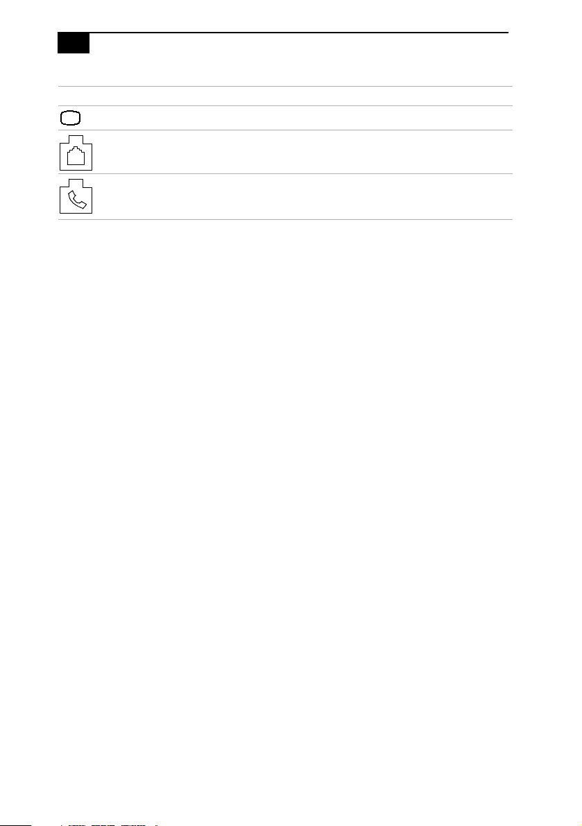
Icon Description
Monitor connector
Line (for telephone line from primary service jack)
Telephone (for phone)
Identifying Components
9
I/O Connectors
The following section identifies the various I/O connectors.
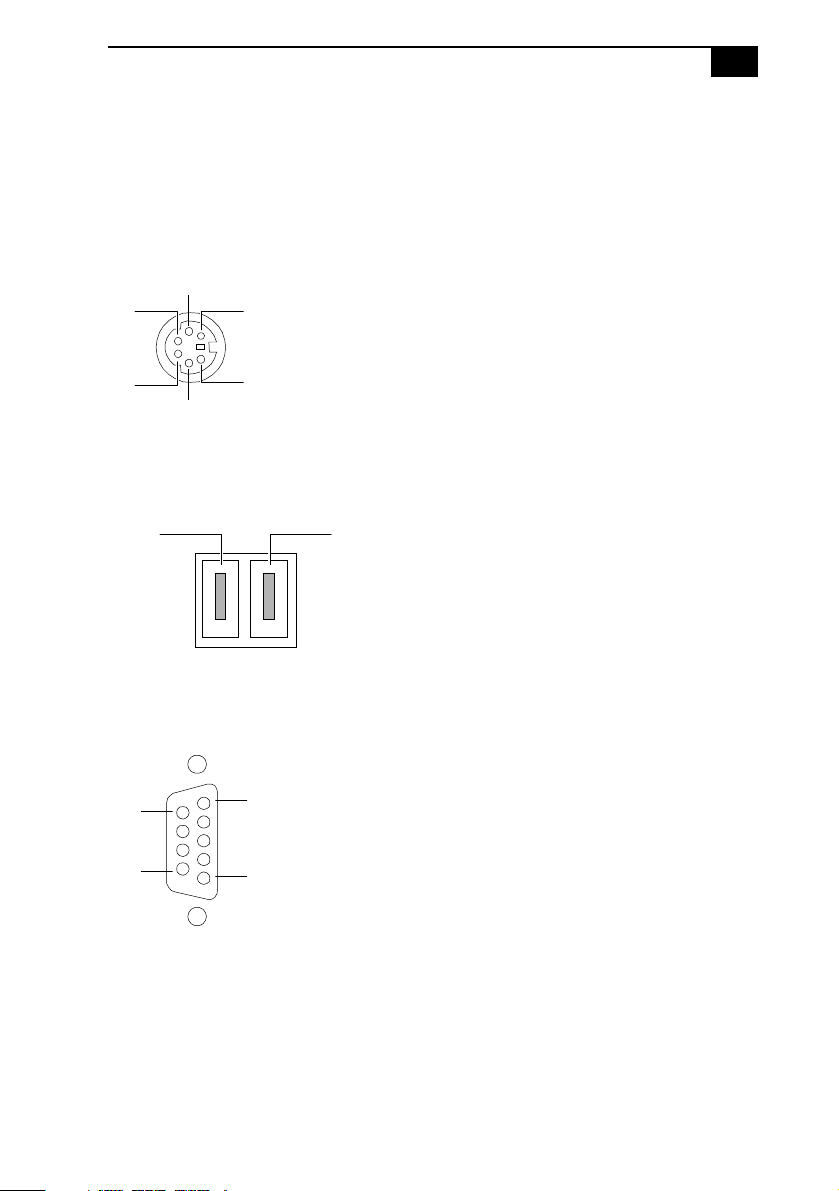
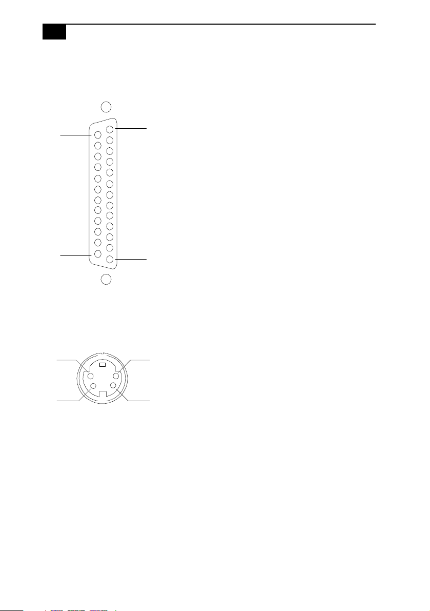
Keyboard and Mouse
The keyboard and mouse connectors are physically identical and have the
same pinout. They are standard 6-pin PS/2-type female connectors.
2
3
1
4
5
6
USB Ports
Port 1 Port 2
Serial Port
The serial port is a standard 9-pin DB-9 male connector.
9
6
5
1
KY0002.VSD
KY0003.VSD
KY0057.VSD
10
VAIO MicroTower System Reference
Printer Port
The printer port is a standard 25-pin DB-25 female connector.
25
14
13
1
S Video Out (PCV-E203/PCV-E205)
The S Video Out connector is a standard 4-pin S Video jack.
3
4
1
2
KY0005.VSD
KY0006.VSD
Identifying Components
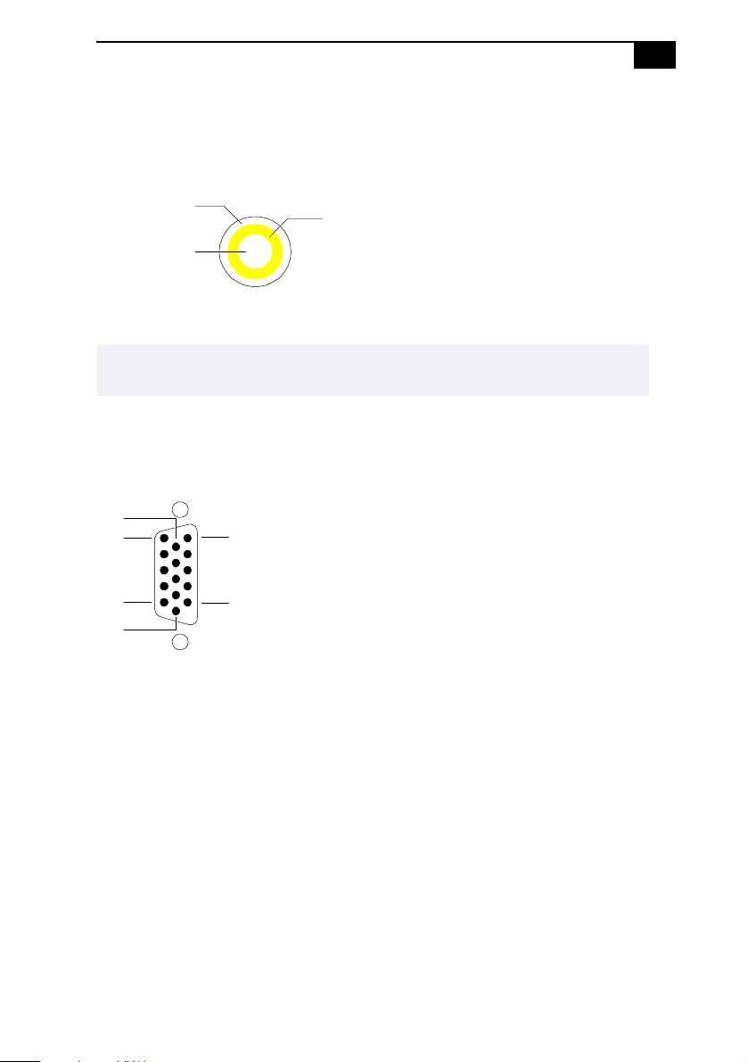
Video Out (PCV-E203/PCV-E205)
The Video Out jack is for composite video. It is a standard RCA phono
jack.
11
Case ground
Signal (center)
Yellow band
KY0007.VSD
WARNING
Do not plug video cables into the wrong connectors, as this may damage the
!
video card in the computer and the equipment to which it is connected.
Monitor
The Monitor connector is a standard 15-pin female high-density VGAtype connector.
10
15
11
6
5
1
KY0004.VSD
12
D
VAIO MicroTower System Reference
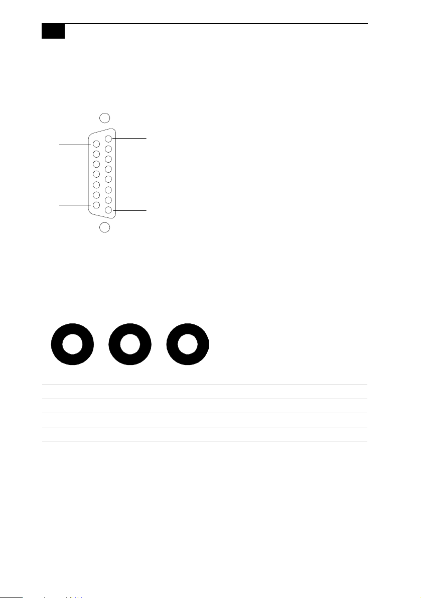
Game Port
The Game port is a standard 15-pin DB-15 female connector. This port is
also used to connect MIDI devices.
15
9
8
1
KY0012.VSD
Mic, Line In, and Headphones
The Mic, Line In, and Headphones jacks are physically identical, but have
different connections. They are standard 3.5 mm stereo mini-jacks.
Headphones Line In Mic
KY0013.VS
Connector Description
Headphones 1.0 Vrms (typical)
Mic Electrolet condenser microphone input
Line In 1.0 Vrms (typical), 10 Kohm impedance
Identifying Components
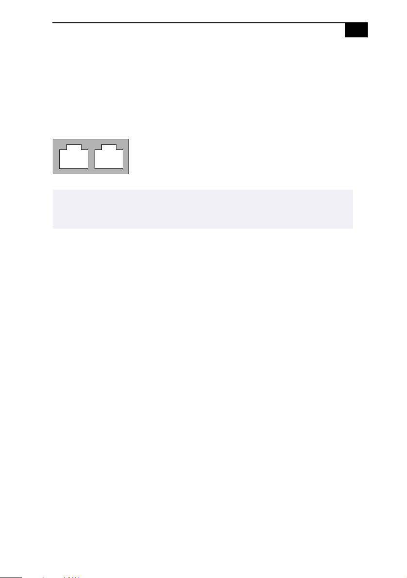
Telephone and Line
13
The Telephone and Line jacks are physically identical and have identical
connections. They are standard RJ-11 female phone jacks. However, the
Line jack is for connecting to a telephone line that comes from the wall,
and the Telephone jack is for connecting the computer to a telephone.
Line Telephone
KY0014.VSD
✍
Accidentally plugging a phone line from the wall into the modem’s Telephone jack, and a
telephone into the Line jack, will not damage the modem card or telephone equipment.
However, the modem may not work correctly.
14
VAIO MicroTower System Reference
Expansion Slots
Two dedicated PCI slots are available for expansion. The ISA slot is
occupied by the fax/modem card.
PCI
PCI
ISA
OM04577B.VSD

Chapter 2
Configuring Your System
This chapter contains information on configuring your system.
Configuring your system can consist of the following:
❑
Making changes to the BIOS settings
❑
Making changes to the display's power management settings
❑
Changing the system board jumper position
15

16
VAIO MicroTower System Reference
Accessing the BIOS Setup Utility
You must access the BIOS Setup Utility to make changes to the BIOS
settings (see “BIOS Setup Options” on page 69 for information on BIOS
settings).
WARNING
Before rebooting the system, save any open files and exit Windows®.
Reboot the system. The following message appears during the inital
1
boot sequence:
Press <F3> for Boot screen
Press F3. The following message appears.
2
Press <F2> for setup.
Press F2.
3
Each menu presents options for modifying the system configuration.
Use the left and right arrow keys to select a menu from the menu bar.
Use the up and down arrow keys to select items within a menu. Once
an item is highlighted, use the plus/minus (+/-) keys to modify a
setting.
If an item has a triangle ( ) to its left, this indicates that a sub-menu of
options is available. Press ENTER to access a sub-menu. If a submenu contains items with a triangle, there is another layer of options
from which to select.
Once you select an option, press ESC to back out of each menu until
4
you reach the top level, where the menu bar appears.
To exit the BIOS setup utility, press ESC from any top-level screen and
5
follow the prompts.
Configuring Your System
17
Changing the Display's Power-management Settings
A display that has power management capability is designed to operate
on reduced power or shut itself off after the system has been idle for a
specified period of time.
From the
1
Double-click the Display icon.
2
Click the Screen Saver tab.
3
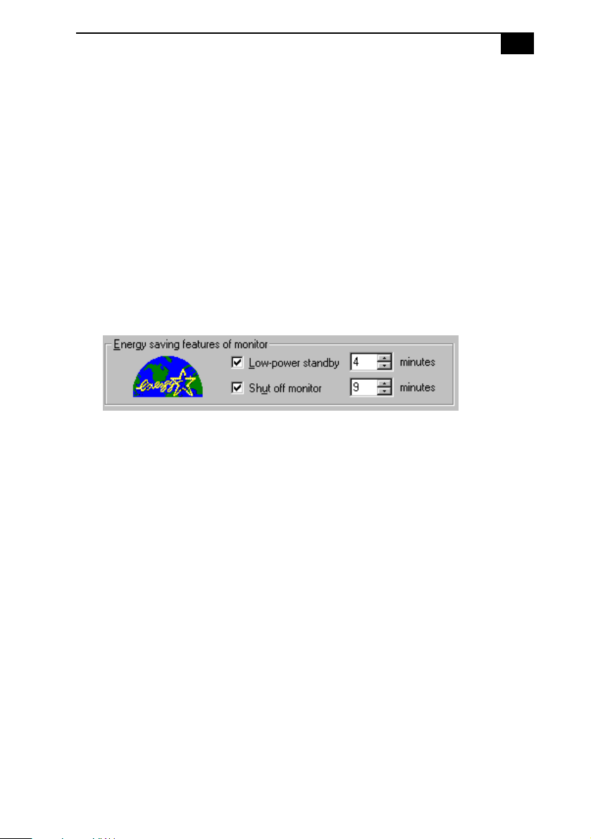
If your display is Energy-Star compliant or has other energy-saving
features, the Energy saving features of the monitor dialog box appear.
Otherwise, the options in the dialog box are grayed out.
Select Low-power standby or Shut off monitor.
4
Selecting Low-power standby blanks the screen (similar to a screen
saver) and automatically reduces power to the display after a
specified amount of time. The display reactivates when you move the
mouse or press a key (as long as the keyboard or mouse are not USB
devices).
Selecting Shut off monitor automatically turns off the display if the
system has been idle for a specified amount of time. Power is
reactivated when you move the mouse or press a key (as long as the
keyboard or mouse are not USB devices).
Start
menu, point to Settings, then click Control Panel.
OM05228.VSD
Select the number of minutes to wait between the last keyboard or
5
mouse activity and activation of the power-management settings.

18
VAIO MicroTower System Reference
Configuring the System Board
The system board contains two configuration jumpers that provide three
modes of operation: Normal mode, Clear Password mode, and BIOS
Recovery mode.
Normal mode allows normal access to the BIOS Setup Utility. The Central
Processing Unit (CPU) input clock is forced to remain at 66 MHz (fast
mode), and the Basic Input/Output System (BIOS) uses the User CMOS
settings (as opposed to the System CMOS settings). The CMOS and
NVRAM settings are only cleared if the checksum test returns false.
Access to specific setup fields is controlled by a supervisor password or
user password.
Clear Password mode removes the password that is stored in CMOS.
BIOS Recovery mode sets the CPU input clock to 66 MHz (fast mode) and
attempts to perform a blind BIOS update. If the recovery fails, beep codes
alert you to the failure and the system waits for the insertion of a boot
diskette in the A drive. No video is enabled at this point.
✍
The configuration jumpers should never need changing unless otherwise directed by a
technical support or service technician.
WARNING
Before opening the system, save any open files, exit Windows, turn off the power
of the computer and all attached peripherals, and unplug the power cord.
Remove the side panel (see “Removing the Side Panel” on page 22).
1
Remove the bottom panel (see “Removing the Bottom Panel” on
2
page 23).
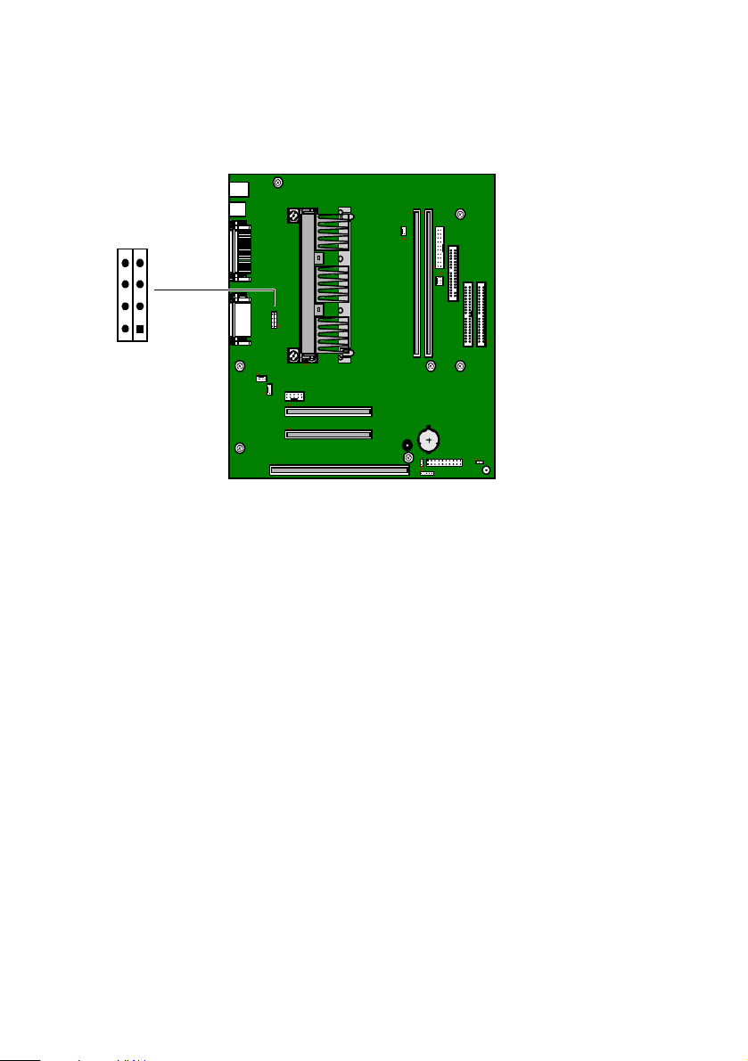
Set the jumpers as directed by a service technician (also see
3
“Configuration Jumpers” on page 63).
JP1
CPU
SPEED
Reinstall the bottom panel (see “Removing the Bottom Panel” on
4
page 23).
Reinstall the side panel (see “Reinstalling the Side Panel” on page 27).
5
OM04588.VSD
19

20

Chapter 3
Removing, Installing and Reinstalling Components
This chapter describes removing, installing, and reinstalling major
components for upgrading, reconfiguring, replacing, or troubleshooting
the components.
WARNING
Before opening the system, save any open files, exit Windows, turn off the power
of the computer and all attached peripherals, and unplug the power cord.
21
22
VAIO MicroTower System Reference
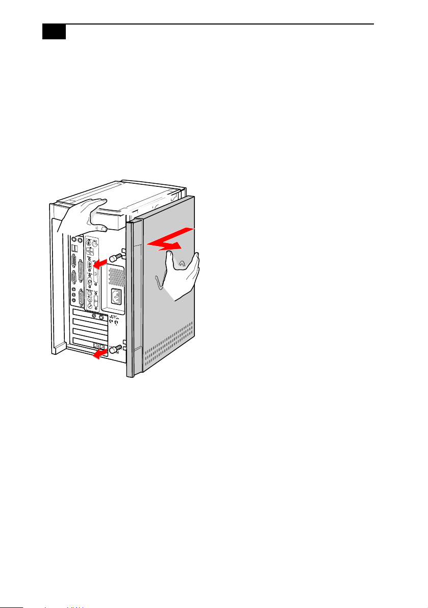
Removing the Side Panel
You must remove the side panel to access the system board, add-in cards,
power supply, battery, and internal drives.
From the rear of the unit, remove the two thumb screws that secure
1
the panel to the chassis.
Slide the side panel back with your right hand as you hold the chassis
2
in position with your left hand. The panel slides back about ½ inch.
Pull the panel straight out to remove it.
3
KY0064.VSD
 Loading...