

Page 1

4-179-788-17 (1)
HD VISUAL
COMMUNICATION
SERVER
Operating Instructions (Version 6.0)
Before operating the unit, please read this manual thoroughly and retain it for
future reference.
PCS-VCS
© 2010 Sony Corporation
Page 2

Notation used in this Manual
Menu, Icon, Button
and Tab Operations
Directory and Menu
Selection
Reference Denote reference source by enclosing with “ ”
Screen Captures
Screen captures are shown throughout this manual as typical examples of the
program operation. As such, the screens shown in this manual may differ from
the actual screens displayed on your terminal.
Trademarks
• HD VISUAL COMMUNICATION SERVER is a product of the Sony
Corporation.
• “IPELA” and are trademarks of Sony Corporation.
• HD VISUAL COMMUNICATION SERVER uses the Visual Nexus
developed by Oki Electric Industry Co., Ltd.
• Visual Nexus and the Visual Nexus logo are the registered trademarks of Oki
Electric Industry Co., Ltd.
• Microsoft, NetMeeting, Windows and PowerPoint are trademarks or
registered trademarks of Microsoft Corporation in the United States and
other countries.
• Intel, Pentium, Xeon and Celeron are trademarks or registered trademarks of
Intel Corporation in the United States and other countries.
• SONY is a trademark of Sony Corporation.
• Red Hat is a trademark or registered trademark of Red Hat, Inc. in the United
States and other countries.
• Linux is a trademark of Linus Torvalds.
• Other company names or product names noted in this manual are the
trademarks or registered trademarks of their respective owners.
Denote by enclosing with [ ]
E.g. Click [Cancel] button.
[Main Menu Name] t [Sub Menu Name]
E.g. Select [Program] t [Internet Explorer]
E.g. Refer to “About this Document”
2
Page 3

Table of Contents
Chapter 1: HD VISUAL COMMUNICATION SERVER
Overview
System Overview ..................................................................................................... 6
Meetings ................................................................................................................... 7
H.323 Alias and Gatekeeper .................................................................................... 8
Chapter 2: HD VISUAL COMMUNICATION SERVER Setup
VC ONLINE Login .................................................................................................. 9
License ................................................................................................................... 10
Confirm License ............................................................................................... 10
Starting and Stopping the HD VISUAL COMMUNICATION SERVER ............ 11
HD VISUAL COMMUNICATION SERVER Manual Startup ....................... 11
HD VISUAL COMMUNICATION SERVER Manual Close ......................... 11
HD VISUAL COMMUNICATION SERVER Processes ..................................... 12
Chapter 3: Basic Configuration
Creating a User ....................................................................................................... 13
Create User Information ................................................................................... 13
Edit User Information ....................................................................................... 17
Delete User Information ................................................................................... 17
Create a User Template .................................................................................... 18
Search Filter in User List .................................................................................. 19
Configuring User Groups ....................................................................................... 20
Configure a New Group ................................................................................... 20
Edit Group Information .................................................................................... 21
Delete Group Information ................................................................................ 22
Search Filter in Group List ............................................................................... 22
Configuring a Meeting ........................................................................................... 23
Configure Meeting Information ....................................................................... 23
Edit Meeting Information ................................................................................. 29
Search Filter in Meeting List ............................................................................ 29
Chapter 4: Using Meetings (Basic)
Monitor Function ................................................................................................... 30
3
Page 4

Monitor Endpoint Information ......................................................................... 30
Monitor Meeting Information .......................................................................... 32
Monitor Call Information ................................................................................. 35
Calling to a Meeting .............................................................................................. 36
Calling an Endpoint to a Meeting via the [Monitor (Endpoint)] Screen .......... 36
Calling an Endpoint to a Meeting via the [Monitor (Meeting)] Screen ........... 37
Disconnecting an Endpoint from a Meeting .......................................................... 39
Disconnect an Endpoint from a Meeting List .................................................. 39
Chapter 5: Using Meetings (Application)
Scheduling Meetings .............................................................................................. 40
Suppressing Video Refresh Requests from Endpoints .......................................... 42
Using the Share Phone Book ................................................................................. 43
Using Templates .................................................................................................... 44
Configuring Audio Details ..................................................................................... 45
Changing Transmission Resolutions for Endpoints with Insufficient
Throughput ............................................................................................................. 46
Using the Encryption Function .............................................................................. 47
Configuring Video Details ..................................................................................... 48
Restricting Meeting Users ..................................................................................... 50
Conducting Moderated Meetings ........................................................................... 51
Moderate a Meeting ......................................................................................... 51
Conducting Multiple Video Screen Meetings ....................................................... 53
Multiple Video Screen Layout ......................................................................... 54
Upstream Resolution from Endpoints .............................................................. 57
Chapter 6: Using the Reservation System
About the Reservation System ............................................................................... 58
Configuring the Reservation System ..................................................................... 59
Creating a Reservation Template ........................................................................... 60
Reserving a Meeting .............................................................................................. 61
Verify Personal Reservation Schedules ........................................................... 64
Edit Reservation Settings ................................................................................. 64
Delete Reservations .......................................................................................... 65
Deleting a Completed Meeting .............................................................................. 66
Chapter 7: Server Monitoring
Confirming HD VISUAL COMMUNICATION SERVER Status ....................... 67
4
Page 5

Chapter 8: Gatekeeper
Restricting Registrations ........................................................................................ 69
Restrict Registrations ....................................................................................... 69
Edit Registration Restrictions ........................................................................... 71
Delete Restriction Information ......................................................................... 71
Chapter 9: VCMP Servers
About VCMP Servers ............................................................................................ 72
Registering VCMP Servers .................................................................................... 73
Register VCMP Server Information ................................................................. 73
Edit VCMP Server Information ....................................................................... 74
Chapter 10: Additional Configuration
ARQ (Automatic Repeat ReQuest) Function ......................................................... 75
Configuring Personal Information ......................................................................... 76
Sending an E-mail to other Users .......................................................................... 78
Reporting ................................................................................................................ 79
Sony PCS-XG/XL/XA/XC Series Firmware Update Function ............................. 81
Setup ................................................................................................................ 81
Firmware Update Procedure ............................................................................. 81
Status Display ................................................................................................... 82
Linking to the HD RECORDING SERVER .......................................................... 83
Configure the HD RECORDING SERVER Link ............................................ 83
Appendix
List of Terms .......................................................................................................... 85
Menu Components ................................................................................................. 89
5
Page 6

Chapter 1: HD VISUAL COMMUNICATION SERVER Overview
System Overview
HD VISUAL COMMUNICATION SERVER
The HD VISUAL COMMUNICATION SERVER is a multipoint connection
unit (MCU) that is in complete compliance with the H.323 protocol. It is
compatible with multipoint voice synthesis, voice-activated video switching,
etc., and provides central management of functions used for creating,
scheduling and editing meetings. An H.323 gatekeeper is also embedded in the
server.
Note
This software is intended to be used on a server installed on a secure network, such as
a corporate LAN. In operating environments where access from the Internet is possible
or where unspecified access is frequent, take appropriate security measures by using
network devices, for example.
6 System Overview
Page 7

Meetings
The virtual spaces or locations for conducting communications via the HD
VISUAL COMMUNICATION SERVER are referred to as “Meetings”.
This is the equivalent of a conference room in traditional video conferencing
systems.
Meeting types can either be “Normal” or “Presentation”. Users can select
which type of meeting they wish, according to their requirements.
Type Explanation
Normal The standard HD VISUAL COMMUNICATION SERVER meeting
Presentation The general term for meetings with controlled audio communications.
Chapter 1: HD VISUAL COMMUNICATION SERVER Overview
type.
No User serves as the meeting administrator. All meeting participants
have the same privileges.
Access VC ONLINE via a web browser, and permit speaking by using
the [Control Panel].
There are two types of participants in this meeting type, each having
different privileges. The meeting [Chairman] operates the meeting on
behalf of the “General Users.”
The meeting Chairman can change the meeting mode by granting
General Users permission to speak.
Open Forum: Participants can hear the Chairman and those the
Chairman has granted permission to speak.
Side Meeting: Only the Chairman and those the Chairman has
granted permission to speak can hear each other. Conversations cannot
be heard by participants who have not been granted permission to
speak.
Presenting: Only the Chairman can be heard by all participants.
Lecture: Under default conditions, only the Chairman can be heard
by all participants. In such cases, the video of the Chairman and those
specified by the Chairman appear on the General Users’ screens, while
video of each General User appears on the Chairman’s screen in a
multiple video screen layout.
If the Chairman grants a General User permission to speak, the
Chairman and this General User will be heard by all participants. In
such cases, the screens of each of the General Users will switch to a
multiple video screen layout displaying the Chairman and the user the
Chairman has granted permission to speak.
Note
You can not change modes while a meeting conducted in [Lecture] mode is
in progress.
Online communication provided by HD VISUAL COMMUNICATION
SERVER enables meetings to be held among several individuals or person-toperson (one-on-one).
Meetings involving several members must first be registered by the system
administrator.
Person-to-person meetings can be undertaken using direct communications via
an H.323 Alias or E.164 Number.
7Meetings
Page 8

H.323 Alias and Gatekeeper
An H.323 Alias is a unique name assigned for each H.323 terminal, User or
Meeting. The User name of a H.323 terminal registered with the gatekeeper is
assigned as the User’s H.323 Alias.
This system is used because having a set of easily-identifiable numbers or
characters to designate other Users is a much simpler method than using IP
Addresses. Assigning an H.323 Alias to a Meeting configured on the HD
VISUAL COMMUNICATION SERVER allows each terminal to directly
enter Meetings using an H.323 Alias.
The gatekeeper embedded in the HD VISUAL COMMUNICATION
SERVER holds H.323 Alias and IP Address information for all registered
Endpoints and Meetings. This makes it easy to enter Meetings and call other
Users with an H.323 Alias.
The H.323 Alias can be assigned during the following configuration tasks:
• User H.323 Alias: When providing / changing User information settings
• Meeting H.323 Alias: When providing / changing Meeting information
settings
8 H.323 Alias and Gatekeeper
Page 9

Chapter 2: HD VISUAL COMMUNICATION SERVER Setup
VC ONLINE Login
To use HD VISUAL COMMUNICATION SERVER, it is necessary to create
a Meeting and User Account. These operations are carried out by logging into
VC ONLINE via a Web browser.
When using VC ONLINE, login via the Administrator restricted account
accessed from the following URL.
URL: http://[HD VISUAL COMMUNICATION SERVER address]:8080/
Login Account: Administrator
Logging in to VC ONLINE with a general User Account will allow individual
Users to access the scheduling system or make changes to their own
information.
Also, it is possible to get help even without logging in, such as by referring to
the downloadable manual or help document.
Chapter 2: HD VISUAL COMMUNICATION SERVER Setup
For more information about creating a User Account, refer to “Creating a
User” (p. 13).
For more information about configuring a Meeting, refer to “Configuring a
Meeting” (p. 23).
For more information about using the Reservation system, refer to “Chapter
6: Using the Reservation System” (p. 58).
For more information about configuring personal information, refer to
“Configuring Personal Information” (p. 76).
9VC ONLINE Login
Page 10

License
The HD VISUAL COMMUNICATION SERVER license is administered by
the HD VISUAL COMMUNICATION SERVER’s License Server function,
and is calculated by the number of simultaneously concurrent calls.
Server License
License used to access HD meetings.
PC Endpoint License
License for using PC Endpoint.
Firewall Traversal License
License for using Firewall Traversal.
Mobile Endpoint License
License for using Mobile Endpoint.
Confirm License
1 Login to VC ONLINE (http://[HD VISUAL COMMUNICATION
SERVER address]:8080/) using an account with administrator privileges.
2 Select [Licenses] from the [Server] menu.
The [Licenses] screen will be displayed.
10 License
In [License Numbers], confirm the total number of licenses and the current
number of licenses being used.
In [Licenses] (the sub-menu inside the main menu [Licenses]), the license
registration date can be confirmed.
Page 11

Starting and Stopping the HD VISUAL COMMUNICATION SERVER
During installation, the HD VISUAL COMMUNICATION SERVER is
configured to automatically start when the OS starts, and automatically stop
when the OS stops.
HD VISUAL COMMUNICATION SERVER Manual Startup
The procedure for starting the HD VISUAL COMMUNICATION SERVER
by manual command will now be explained.
1 Right-click on the Server Desktop, and click on [Open Terminal] in the
Menu.
The Terminal Software will open.
2 Execute the following command in the terminal software.
# /usr/local/vn/bin/vnstart
HD VISUAL COMMUNICATION SERVER Manual Close
The procedure for closing the HD VISUAL COMMUNICATION SERVER
by manual command will now be explained.
Note
Do not close the HD VISUAL COMMUNICATION SERVER while still using
conference, etc.
1 Right-click on the Server Desktop, and click on [Open Terminal] in the
Menu.
The Terminal Software will open.
Chapter 2: HD VISUAL COMMUNICATION SERVER Setup
2 Execute the following command in the Terminal Software.
# /usr/local/vn/bin/vnstop
Note
After closing the server, wait about one minute before starting it again.
11Starting and Stopping the HD VISUAL COMMUNICATION SERVER
Page 12

HD VISUAL COMMUNICATION SERVER Processes
Processes used in HD VISUAL COMMUNICATION SERVER Version 6.0
will now be explained.
For more information about process confirmation, refer to “How to Display
Processes” (p. 67).
Process Description
cnode_mcu MCU and VCMP control process (CPN)
beam.smp Erlang programming language environment (CPN)
vnncs Network Check Server
vnproxy H.239 Presentation (Data Transmission)
vnutil Utility (Periodical Log cleaning)
vnlmsvr License Server
vnbms Buddy Manager (Presence)
vnpms Presence Manager (Presence)
vngk Gatekeeper
vnmcu MCU
vnvnc H.239 Presentation (Control)
vnapi API Server (interface between programs)
12 HD VISUAL COMMUNICATION SERVER Processes
Page 13

Chapter 3: Basic Configuration
This section describes configuration needed to use HD VISUAL
COMMUNICATION SERVER, such as creating a User and Meeting.
Creating a User
Methods to add, edit and delete User information will now be explained.
A User Account is required to access the HD VISUAL COMMUNICATION
SERVER.
Only the User “Administrator” is created as default during installation.
Create User Information
1 Login to VC ONLINE (http://[HD VISUAL COMMUNICATION
SERVER address]:8080/) with administrator privileges (Administrator).
2 Click on [User] in the [User] Menu.
The [User] screen will be displayed.
3 Click the [Add] button.
The [Add User] screen will be displayed.
Chapter 3: Basic Configuration
Hint
At this stage, a new User can be added by clicking the [Add by Copy] button after
selecting a previously added user from the list, and then by entering the selected User’s
settings underneath.
4 Select a user type in [User Type], and enter a [Login Name].
If necessary, set other items.
For more information about setup items, refer to “[Add User] Screen” (p.
14).
5 When entry is complete, click the [Add] button.
The confirmation dialog box will be displayed.
6 Click [OK].
A User will be added based on the provided information.
13Creating a User
Page 14

Note
The registration data may not be displayed in the VC ONLINE [Users] list immediately
after starting the HD VISUAL COMMUNICATION SERVER due to timing
constraints. In such instances, access it after an interval of time.
[Add User] Screen
Setting Category Description
User ID Number to identify Users accessing HD VISUAL
User Type Type of User account:
Login Name Required field.
Password Required field.
H.323 Alias Required field if [PCEP] or [H.323] is selected for [User Type].
E.164 Number Enter the User number of the endpoint you wish to use, which has
User Template Designate the required User template in order to view registered
Share Phone
Book
COMMUNICATION SERVER.
The System will automatically assign User ID numbers, which
cannot be edited.
PCEP: PC Endpoint terminal
H.323: Dedicated H.323 terminal (set top box, etc.)
FT Client: Firewall Traversal client
SIP: Dedicated SIP Client
Note
This software does not support “SIP”.
Enter Name used to login to HD VISUAL COMMUNICATION
SERVER.
Use alphanumeric characters. Non-alphanumeric characters,
spaces or < > " ' ! \& symbols cannot be used.
Enter Password used to login.
Use alphanumeric characters. Non-alphanumeric characters,
spaces or < > " ' ! \& symbols cannot be used.
Enter the User name of the endpoint you wish to use, which has
been registered with the gatekeeper.
Use alphanumeric characters. Non-alphanumeric characters,
spaces or < > " ' ! \& symbols cannot be used.
been has registered with the gatekeeper.
User templates.
For more information about User templates, refer to “Create a
User Template” (p. 18).
Select whether to display in the Share Phone Book the user
information that is registered on the server.
NONE: Do not display the information in the Share Phone Book.
H323ALIAS: Display the information in the Share Phone Book
using H.323 aliases for the user contact information.
E164NUMBER: Display the information in the Share Phone
Book using E.164 numbers for the user contact information.
IPADDRESS: Display the information in the Share Phone Book
using IP addresses for the user contact information.
14 Creating a User
Page 15

Setting Category Description
Last Name Enter name (Last Name) used to login. This is displayed as [End
Middle Name Enter name (Middle Name) used to login. This is displayed as
First Name Enter name (First Name) used to login. This is displayed as [End
e-mail Enter the User’s e-mail address.
IP Address
Administrator Configure administrator privileges for users.
Point Name].
Alphanumeric / non-alphanumeric (e.g. Japanese) characters and
symbols can be used. Do not use spaces or < > " ' ! \& symbols.
In addition, do not use slashes (/) if you intend to display the user
in the Share Phone Book.
[End Point Name].
Alphanumeric / non-alphanumeric (e.g. Japanese) characters and
symbols can be used. Do not use spaces or < > " ' ! \& symbols.
Note
[End Point Name] will not be displayed if two-byte characters are
used for “Last Name” and “First Name”
Point Name].
Alphanumeric / non-alphanumeric (e.g. Japanese) characters and
symbols can be used. Do not use spaces or < > " ' ! \& symbols.
In addition, do not use slashes (/) if you intend to display the user
in the Share Phone Book.
This is used to receive Meeting notification e-mails.
Enter this when registering the user without registering it with the terminal
gatekeeper. You can leave this blank under normal circumstances.
Administrator: Register the user as an administrator.
User: Specify the user as a general user. General users can only
use the reservation system and edit their personal information.
User (Online browsing restricted): Specify the user as a
general user that cannot access VC ONLINE.
Note
Be sure to register at least one user as an administrator.
Chapter 3: Basic Configuration
[Basic] Tab
Setting Category Description
Max Bandwidth The maximum bandwidth (bit rate) the User can use for calls. In
Application
Sharing
Bandwidth
P2P connections, the maximum bandwidth setting is compared to
that of the other participant, and the lower value is used for the
connection. This setting is also used to determine the
transmission resolution during CPN meetings.
For more information about determining the transmission
resolution, refer to “Changing Transmission Resolutions for
Endpoints with Insufficient Throughput” (p. 46).
Enter the maximum bandwidth (bit rate) the User can use when
the Application Sharing function is used. When the User
connects to a meeting, this setting is compared to the
[Application Sharing Bandwidth] setting of the meeting, and the
connection is made with the lower of the two values.
15Creating a User
Page 16

Setting Category Description
Bandwidth
Setting of PCEP
Profile
FT Connection Select the Firewall Traversal setting.
FT Tunnel Type Select the tunnel type for Firewall Traversal. Configure this only
Select whether to reference the bandwidth configured in the PC
Endpoint profile.
ENABLE: Reference the profile setting.
DISABLE: Do not reference the profile setting.
Autodetect FT: Automatically determine whether Firewall
Traversal is necessary when connecting to the HD VISUAL
COMMUNICATION SERVER, and connect via the FT personal
client only if necessary.
Autodetect GC: Automatically determine whether Firewall
Traversal is necessary when connecting to the HD VISUAL
COMMUNICATION SERVER, and connect via the FT group
client only if necessary.
Use FT: Always use the FT personal client when connecting to
the HD VISUAL COMMUNICATION SERVER.
Use GC: Always use the FT group client when connecting to the
HD VISUAL COMMUNICATION SERVER.
NONE: Connect without using Firewall Traversal.
Note
FT personal clients can only be used from a PC Endpoint terminal.
Therefore, [Autodetect FT] and [Use FT] cannot be used from an
H.323 terminal.
when using Firewall Traversal.
NONE: Do not specify a tunnel type.
TCP: Connect using a TCP tunnel.
UDP: Connect using a UDP tunnel.
[Forwarding] Tab
Setting Category Description
Set Select the checkbox to enable the [Action], [Forwarding Type],
Condition Indicates the status; [Busy], [Online] (User can be called), or
Action Select the [Confirm], [Reject] or [Forward] Action when
Forwarding Type Select the forwarding destination type when selecting [Forward]
16 Creating a User
and [Forwarding Destination] settings. This can be configured for
each [Condition].
[Offline] (User cannot be called). The [Action], [Forwarding
Type], and [Forwarding Destination] settings can be configured
for each status.
answering calls.
as an [Action]
H.323 Alias: When selecting an H.323 Alias as a forwarding
destination.
E.164 Number: When selecting an E.164 Number as a
forwarding destination.
IP Address: When selecting an IP Address as a forwarding
destination.
Page 17

Setting Category Description
Forwarding
Destination
Edit User Information
1 Login to VC ONLINE (http://[HD VISUAL COMMUNICATION
SERVER address]:8080/) using an account with administrator privileges.
2 Click on [User] from the [User] menu.
The [User] screen will be displayed.
3 Select the User you wish to edit from the [Users] list.
The [Change] button will be displayed.
4 Click the [Change] button.
The [Edit User] screen will be displayed.
5 Make the desired changes.
For more information about setup items, refer to “[Add User] Screen” (p.
14).
6 Click the [Change] button from the [Edit User] screen.
The confirmation dialog box will be displayed.
When selecting [Forward] as an [Action], enter a forwarding
destination that complies with a type specified in the [Forwarding
Type].
Chapter 3: Basic Configuration
7 Click [OK].
The edited information will be saved.
Delete User Information
1 Login to VC ONLINE (http://[HD VISUAL COMMUNICATION
SERVER address]:8080/) using an account with administrator privileges.
2 Click on [User] from the [User] menu.
The [User] screen will be displayed.
3 Click the checkbox of the User you wish to delete from the [Users] list.
The checked [Delete] button will be displayed.
4 Click the [Delete] button.
The designated User will be deleted.
17Creating a User
Page 18

Create a User Template
The User Template is a template of User Account information.
1 Click on [User Template] from the [User] menu.
The [User Template] screen will be displayed.
2 Click the [Add] button.
The [Add User Template] screen will be displayed.
3 Enter the template name and set other fields as necessary.
For more information about setup items, refer to “[Add User Template]
Screen” (p. 18).
4 Click the [Add] button.
The specified User Template information will be registered.
[Add User Template] Screen
Setting Category Description
Template ID ID number for User Template.
Template Name Required field.
Max Bandwidth The maximum bandwidth (bit rate) the User can use for calls.
Application
Sharing
Bandwidth
Bandwidth
Setting of PCEP
Profile
The System will automatically assign Template ID numbers.
They cannot be entered or edited.
Enter Template name.
Alphanumeric characters will be used. Non-alphanumeric
characters, spaces or symbols cannot be used.
Enter the maximum bandwidth (bit rate) the User can use when
the Application Sharing function is used.
Select whether to reference the bandwidth configured in the PC
Endpoint profile.
ENABLE: Reference the profile setting.
DISABLE: Do not reference the profile setting.
18 Creating a User
Page 19

Setting Category Description
FT Connection Select the Firewall Traversal setting.
Autodetect FT: Automatically determine whether Firewall
Traversal is necessary when connecting to the HD VISUAL
COMMUNICATION SERVER, and connect via the FT personal
client only if necessary.
Autodetect GC: Automatically determine whether Firewall
Traversal is necessary when connecting to the HD VISUAL
COMMUNICATION SERVER, and connect via the FT group
client only if necessary.
Use FT: Always use the FT personal client when connecting to
the HD VISUAL COMMUNICATION SERVER.
Use GC: Always use the FT group client when connecting to the
HD VISUAL COMMUNICATION SERVER.
NONE: Connect without using Firewall Traversal.
Note
FT personal clients can only be used from a PC Endpoint terminal.
Therefore, [Autodetect FT] and [Use FT] cannot be used from an
H.323 terminal.
FT Tunnel Type Select the tunnel type for Firewall Traversal. Configure this only
when using Firewall Traversal.
NONE: Do not specify a tunnel type.
TCP: Connect using a TCP tunnel.
UDP: Connect using a UDP tunnel.
Search Filter in User List
A search filter can be applied in the [User] screen to locate Users from the
[Users] list.
By entering the information you wish to filter in the text box, filter search
results will be displayed.
By default, the search filter will search through the following User account
fields for occurrences of the search string: [Login Name], [Last Name],
[Middle Name], [First Name], [e-mail], [H.323 Alias] and [E.164 Number]. To
disable a field as a condition for the search filter, clear the checkbox of the
respective field.
Chapter 3: Basic Configuration
19Creating a User
Page 20

Configuring User Groups
Methods to add, edit and delete Group information will now be explained.
By adding Group information, multiple users can be combined to form a
Group, and it is possible to make groups belong to another group.
Users and Groups can also belong to more than one User Group
The use of User Groups is convenient when configuring access control and the
reservation system.
New Groups can be created and configured with the required Users as and
when necessary.
“Default” Groups registered when the system is first used include all registered
User accounts.
Configure a New Group
1 Login to VC ONLINE (http://[HD VISUAL COMMUNICATION
SERVER address]:8080/) using an account with administrator privileges.
2 Click on [Group] from the [User] menu.
The [Group] screen will be displayed.
3 Click the [Add] button.
The [Add Group] screen will be displayed.
4 Enter the [Group Name] and set other fields as necessary.
For more information about setup items, refer to “[Add Group] Screen”
(p. 21).
5 Click the [Add] button.
The confirmation dialog box will be displayed.
6 Click [OK].
The new Group information specified will be registered.
20 Configuring User Groups
Page 21

[Add Group] Screen
Setting Category Description
Group ID ID number used to identify HD VISUAL COMMUNICATION
Group Name Required field.
Subordinate User Add Subordinate Users to a Group
Subordinate
Group
Edit Group Information
1 Login to VC ONLINE (http://[HD VISUAL COMMUNICATION
SERVER address]:8080/) using an account with administrator privileges.
SERVER Groups.
The System automatically assigns Group ID numbers, which
cannot be edited.
Enter the Group name.
Alphanumeric / non-alphanumeric characters and symbols can be
used.
From the displayed User list, select the checkbox next to the User
name you wish to add.
Add Subordinate Groups to a Group
From the displayed Group list, select the checkbox next to the
Group name you wish to add.
With this function, it is possible to configure and manage Groups
using a hierarchical structure.
Note
It is not possible to add Groups located in a superior position to your
own Group.
Chapter 3: Basic Configuration
2 Click [Group] from the [User] menu.
The [Group] screen will be displayed.
3 Select the Group you wish to edit from the [Groups] list.
The [Change] button will be displayed.
4 Click the [Change] button.
The [Edit Group] screen will be displayed.
5 Make the necessary changes.
For more information about setup items, refer to “[Add Group] Screen”
(p. 21).
6 Click on [Change] from the [Edit Group] screen.
The confirmation dialog box will be displayed.
7 Click [OK].
The edited information will be saved.
21Configuring User Groups
Page 22

Delete Group Information
1 Login to VC ONLINE (http://[HD VISUAL COMMUNICATION
SERVER address]:8080/) using an account with administrator privileges.
2 Click [Groups] from the [User] menu.
The [Groups] screen will be displayed.
3 From the [Groups] list, select the checkbox next to the Group you wish to
delete.
The checked [Delete] button will be displayed.
4 Click the [Delete] button.
The denoted Group will be deleted.
Search Filter in Group List
A search filter can be executed in the [Groups] screen to locate Groups from
the [Groups] list.
By entering the information you wish to filter in the text box, filter search
results will be displayed.
22 Configuring User Groups
Page 23

Configuring a Meeting
Methods to add, edit and delete Meeting information will now be explained.
Meetings can be seen as a virtual conference room. Meeting settings are
diverse so they can be set according to your meeting agenda.
Note
Because it takes time to add a Meeting or to change a setting, there will be a delay of
approximately 15 seconds before a sound connection can be made after adding or resetting a Meeting or following the conclusion of a Meeting.
Configure Meeting Information
1 Login to VC ONLINE (http://[HD VISUAL COMMUNICATION
SERVER address]:8080/) using an account with administrator privileges.
2 Click on [Meeting] from the [Meeting] menu.
The [Meeting] screen is displayed.
3 Click the [Add] button.
The [Add Meeting] screen is displayed.
Hint
At this stage, a new Meeting can be added by clicking the [Add by Copy] button
after selecting a previously added Meeting from the list, and then by inserting the
selected Meeting’s settings underneath.
For more information about setup items, refer to “[Add Meeting] Screen” (p. 24).
4 Enter the [Meeting Name] from the [Basic] tab.
Set other Meeting items as required. If items apart from [Meeting Name]
are not entered or edited, then default settings will be used.
5 Click the [Add] button.
The confirmation dialog box will be displayed.
6 Click the [OK] button.
The specified meeting information will be added.
Notes
• By default, the maximum number of usable Meetings, such as normal Meetings or
scheduled Meetings that can be held on the HD VISUAL COMMUNICATION
SERVER is 100.
• The maximum connection time for a meeting is 8 hours. After 8 hours elapse from the
start of a meeting, connections for all terminals will be severed.
Chapter 3: Basic Configuration
23Configuring a Meeting
Page 24

[Add Meeting] Screen
For information about the [Detail], [Access], [Presenter] and [VCMP] tabs,
refer to “Chapter 5: Using Meetings (Application)” (p. 40).
[Basic] Tab
Setting Category Description
Meeting ID ID number used to identify HD VISUAL COMMUNICATION
Meeting Name Required field.
H.323 Alias Enter the H.323 Alias assigned to a Meeting.
E.164 Number Enter the E.164 number assigned to a Meeting.
Max Members Required field.
Meeting Type Selects the Meeting Type.
SERVER Meetings.
The system will automatically assign Meeting ID numbers. This
cannot be entered or edited.
Enter the Meeting name.
Alphanumeric / non-alphanumeric (e.g. Japanese) characters and
symbols will be used. Spaces and < > " ' ! \ & symbols cannot
be used.
The User will select the Meeting Name. A unique, easy-tounderstand name should be selected for the Meeting.
Alphanumeric characters will be used. Non-alphanumeric
characters, spaces and < > " ' ! \ & cannot be used. An H.323
alias cannot contain only numerical character numbers; it must
also include alpha characters. If nothing is entered, it will be
automatically assigned when registering.
Enter the maximum number of Meeting members.
Note
If the configured maximum number of participants exceeds that
allowed by the Server License, no error will be displayed but the
number of participants will be restricted to the license value.
Normal: There is no meeting chairman, so all participants have
the same right to speak. Suitable mostly for small meetings with
only a few participants.
Loopback: Used to verify the Endpoint connection.
Note
When [Loopback] is selected, [CPN] will be set to [OFF].
Moderated: Selected when the Meeting chairman controls the
audio of other participants.
Note
When using the Moderated Meeting type, it is necessary to configure
the Meeting participants and Chairman. Select the participants from
[Access List(Group) ] or [Access List(User) ] under the [Access] tab.
When Users selected from the [Access] tab are displayed in the
[Presenter] tab list, select 1 person to be the Chairman.
24 Configuring a Meeting
Page 25

Setting Category Description
Meeting Mode Selects the initial mode for the Moderated Type Meeting.
These modes are only valid when the selected [Meeting Type] is
[Moderated].
Open Forum: Participants can hear the Chairman and those the
Chairman has granted permission to speak.
Side Meeting: Only the Chairman and those the Chairman has
granted permission to speak can hear each other. Conversations
cannot be heard by participants who have not been granted
permission to speak.
Presenting: Only the Chairman can be heard by all
participants.
Lecture: Under default conditions, only the Chairman can be
heard by all participants. In such cases, only the Chairman’s
video appears on the General Users’ screens, while video of each
General User appears on the Chairman’s screen in a multiple
video screen layout.
If the Chairman grants a General User permission to speak, the
Chairman and this General User will be heard by all participants.
In such cases, the screens of each of the General Users will
switch to a multiple video screen layout displaying the Chairman
and the user the Chairman has granted permission to speak.
Notes
• You can not change modes while a meeting conducted in [Lecture]
mode is in progress.
• When [CP4] is selected for an SD resolution (CIF, 4CIF) in
[Lecture] mode, the Chairman’s display will be split into a 4-screen
layout, but the General Users’ displays will not. Instead, the CP
layout of General Users will change according to the number of
participants that have been granted permission to speak.
Operator Mode Configure this mode for meetings in which the Chairman simply
controls the speakers and display modes, without actively
participating.
These modes are only valid when the selected [Meeting Type] is
[Moderated].
Disable: Disables use of the Operator Mode.
MIC OFF: Permission to speak is not granted to any participants
at the start of the meeting.
MIC ON: Grants all participants permission to speak at the start
of the meeting.
Note
[Operator Mode] can only be used when the selected [Meeting Mode]
is [Open Forum].
Bandwidth
Control
Selects the method for controlling the Meeting bandwidth.
STATIC: Each endpoint that enters the conference is limited to
the bandwidth configured in the [Max Bandwidth (ep)]
parameter.
DYNAMIC: The server will dynamically allocate the bandwidth
equally among the Meeting participants. The bandwidth set for
[Max Bandwidth (ep)] is the maximum endpoint bandwidth.
Once the Meeting Bandwidth has reached the value set in [Max
Bandwidth (conf)], the server will automatically adjust the
bandwidth allocated to each endpoint.
Chapter 3: Basic Configuration
25Configuring a Meeting
Page 26

Setting Category Description
Max Bandwidth
(conf)
Maximum
Bandwidth (ep)
Audio Codec Selects audio codec.
Video If [Disable] is selected, an audio-only meeting will be created,
CPN If [ON] is selected, [CPN Layout Number] selection is enabled,
Video Codec Video Codec is selected from [H.261], [H.263], [H.263+],
Required field. Enter the required maximum Meeting Bandwidth.
When the [Bandwidth Control] is [STATIC], calls that exceed the
below calculation formula for the “Total Meeting Bandwidth” are
not connected in principal.
When the [Bandwidth Control] is [DYNAMIC], configured
bandwidth is shared equally between participants. In such a case,
the number of people configured in [Max Members] will exceed
the number of Meeting participants.
Transmission/Reception Bandwidth of a Terminal = Maximum
Bandwidth (ep) × 2
Total Meeting Bandwidth = (Transmission/Reception Bandwidth
of a Terminal) × Maximum Number of Participants
Required field. Enter the maximum bandwidth used when
Endpoints participating in the meeting transmit audio and video
bandwidth.
Meetings held via the HD VISUAL COMMUNICATION
SERVER are used to select Endpoint transmission bandwidth.
Endpoints cannot send data that exceeds this value.
G.711 µ-law: 3.4 kHz sampling frequency, 64 kbps bit rate
G.711 A-law: 3.4 kHz sampling frequency, 64 kbps bit rate
G.722: 7 kHz sampling frequency, 64 kbps bit rate
MPEG4-AAC-LC: 14 kHz sampling frequency, 32/64 kbps bit
rate
Auto: Use audio transcoding to connect using an audio codec
that can be used by the terminals.
and the video setting then becomes invalid.
For normal Meetings set Video to [Enable], and for audio-only
Meetings, set Video to [Disable].
allowing you to conduct meetings in multiple video screen
layouts.
If [OFF] is selected, [CPN Layout Number] selection is disabled,
allowing you to conduct meetings in only one-screen layouts.
Note
The options that are available for the [Video Codec] and [Resolution]
settings differ depending on whether [ON] or [OFF] is selected here.
[H.264], [H.264 High Profile], or [H.264 Auto].
Note
[H.261] and [H.263+] cannot be selected if the [CPN] setting is
set to [OFF].
26 Configuring a Meeting
Page 27

Setting Category Description
Resolution Selects video resolution. It refers to the size of the downstream
Video Switch
Mode
Video Switch
Time
CPN Layout
Number
H.239 The H.239 Presentation function can be used to send computer
H.239 Bandwidth Enter the bandwidth to use for H.239.
terminal when using multiple video screens. Options to set
Resolution differ depending on the [CPN] and [Video Codec]
configurations.
CIF: Size - (352×288)
4CIF: Size - (704×576)
W432P: Size - (768×432)
HD 720p: Size - (1280×720)
HD 1080p: Size - (1920×1080)
For more information about restrictions to the [Resolution]
setting according to [CPN] and [Video Codec] configurations,
refer to “Restrictions According to [CPN] and [Video Codec]
Configurations” (p. 48).
Note
“Upstream” refers to transmissions from an Endpoint to a Meeting,
whereas “Downstream” refers to transmissions from a Meeting to an
Endpoint.
Selects the method for video switching during a Meeting.
Audio: A method called “Voice Activation” that enables video
switching in response to audio.
Time: Video switches at a set time interval, defined by the Video
Switch Time parameter.
Chairman: The Chairman controls the video for all Endpoints
in the Meeting. This mode is only available in a Moderated Type
Meeting.
Only available when [Time] is selected as the [Video Switch
Mode]. Enter the video screen switch time.
This setting can only be configured when the [CPN] setting is set
to [ON].
Selects the maximum number of screens that can be displayed in
a layout during meetings.
The values that can be selected differ according to video quality.
SD Quality (CIF or 4CIF): Select from 1, 3, 4, 6, 8, 10, 13, or
16.
HD Quality (W432P or HD 720p): Select from 1, 2, 3, 4, 8,
10, 13, or 16.
HD Quality (HD 1080p): Select from 4 or 16.
The video layout of a CPN Meeting changes dynamically
depending on the number of connected Endpoints.
For more information about layout transitions according to the
number of connected Endpoints, refer to “Multiple Video Screen
Layout” (p. 54).
images such as RGB images simultaneously with audio and video
from terminals on the HD VISUAL COMMUNICATION
SERVER.
Under default conditions, this is set to half the value specified in
[Max Bandwidth (ep)].
Chapter 3: Basic Configuration
27Configuring a Meeting
Page 28

Setting Category Description
H.239 Codec Select from [H.263+] or [H.264] for the codec to use for H.239.
Note
Select [H.263+] when conducting meetings that include SD quality
Endpoints. If you select [H.264], H.239 is not sent to the SD quality
Endpoints.
H.239 Resolution Only available when [H.264] is selected for [H.239 Codec].
Application
Sharing
Application
Sharing
Bandwidth
Hints
• When connecting Meetings using H.239 with a specified [Max Bandwidth (ep)],
bandwidths specified as [H.239 Bandwidth] will be used with [H.239] and the
remaining audio bandwidth will be subtracted and used as video bandwidth.
However, if the video bandwidth is lower than 128 Kb/s, that 128 Kb/s will be saved
for video bandwidth and the remaining bandwidth will be allocated to H.239.
• Apart from the [Max Bandwidth] category which is used to set video and audio
bandwidth, [H.239 Bandwidth] can be used to configure bandwidth used for H.239
Presentations.
H.239 Presentation bandwidth restriction is applied to the transmission of application
images.
• The bandwidth used for connections between the sending Endpoint and the server
will be determined by comparing the H.239 rate setting of the terminal and the
[H.239 Bandwidth] of the Meeting, and selecting the one with the lower value for
transmission.
• The Meeting’s [H.239 Bandwidth] will be used when transmitting from the server
to the receiving endpoint.
Select from [XGA], [HD 720p], or [HD 1080p].
This will be fixed at [XGA] when [H.263+] is selected for [H.239
Codec].
Select [ON] to use the Application Sharing function of PC
Endpoint.
Enter the maximum bandwidth used for the Application Sharing
function.
The default setting is [2048] Kbps.
Note
If [H.239] is set to [ON], there may be problems displaying video on H.323 terminals
that do not support H.239. In such a case, set the Meeting’s [H.239] to [OFF].
About Bandwidth
[Maximum Bandwidth (ep)] refers to the maximum bandwidth each endpoint
in the meeting can use for transmissions per channel.
[Max Bandwidth] defines total audio and video stream bandwidth that can be
used for a meeting.
When [Bandwidth Control] is set to [STATIC], a Meeting cannot be connected
if participants’ total bandwidth exceeds [Max Bandwidth] even if the
maximum number of members has not been exceeded.
28 Configuring a Meeting
Page 29

When [Bandwidth Control] is set to [DYNAMIC], the [Max Bandwidth] is
allocated equally among the Meeting members. However, the number of
people participating in a Meeting cannot exceed the specified [Max Members].
Edit Meeting Information
1 Login to VC ONLINE (http://[HD VISUAL COMMUNICATION
SERVER address]:8080/) using an account with administrator privileges.
2 Click on [Meeting] from the [User] menu.
The [Meeting] screen will be displayed.
3 Select the Meeting you wish to edit from the [Meetings] list.
The [Change] button will be displayed.
4 Click the [Change] button.
The [Edit Meeting] screen will be displayed.
5 Make the required changes.
For more information about setup items, refer to “[Add Meeting] Screen”
(p. 24).
6 Click the [Change] button on the [Edit Meeting] screen.
The confirmation dialog box will be displayed.
7 Click [OK].
The edited information will be saved.
Search Filter in Meeting List
A search filter can be executed in the [Meeting] screen to locate Meetings from
the [Meetings] list.
By entering the information you wish to filter in the text box, filter search
results will be displayed.
By default, the Search filter will search through the [Meeting Name], [H.323
Alias] and [E.164] fields. To disable a field as a condition for the search filter,
clear the checkbox of the respective field.
Chapter 3: Basic Configuration
29Configuring a Meeting
Page 30

Chapter 4: Using Meetings (Basic)
Methods to start and disconnect Meetings and to view call information
managed by gatekeeper-registered Endpoints as well as by Meetings and the
Gatekeeper will now be explained.
Monitor Function
This function can display a list of call information managed by gatekeeperregistered Endpoints and by Meetings and the Gatekeeper.
The displayed information is updated every 60 seconds.
For more information about the [Control Panel] screen, refer to “[Control
Panel] Screen” (p. 51).
Monitor Endpoint Information
1 Login to VC ONLINE (http://[HD VISUAL COMMUNICATION
SERVER address]:8080/) using an account with administrator privileges.
2 Click on [Endpoint] from the [Monitor] menu.
The [Monitor (Endpoint)] screen will be displayed.
A list of Endpoints registered with the Gatekeeper is displayed in the
[Monitor (Endpoint)] screen.
30 Monitor Function
Page 31

[Monitor (Endpoint)] Screen
Category Description
End Point Name Displays the name identifying each Endpoint.
End Point ID Displays a unique ID that the Gatekeeper applies to each
H.323 Alias Displays H.323 Alias of each Endpoint registered with the
E.164 Number Displays E.164 Number of each Endpoint registered with the
IP Address Displays the Endpoint IP address.
Terminal Type Displays terminal type.
End Point Vendor Displays the vendor information of each Endpoint.
Connection Status Displays current connection status of each Endpoint.
Regist Time Displays duration of time each Endpoint has been registered
The [End Point Name] displays the [First Name], [Middle
Name] and [Last Name] that were set when originally
registering as a User. If [First Name], [Middle Name] and [Last
Name] have not been set, the [H.323 Alias] will be displayed.
Endpoint.
Gatekeeper.
Gatekeeper.
If left blank, that Endpoint’s E.164 number will not be
registered with the Gatekeeper.
MCU: HD VISUAL COMMUNICATION SERVER
H323: H.323 terminal
PCEP: PC Endpoint terminal
Registered: Possible call status registered with Gatekeeper.
Active Call Conference: Connected to Meeting.
Active Call P2P: Both Endpoints are connected via P2P.
with the Gatekeeper.
Chapter 4: Using Meetings (Basic)
How to Confirm Detailed Endpoint Information
Select the required Endpoint in the [Monitor (Endpoint)] screen, and click the
[Detail] button. The [Registed End Point] screen is displayed enabling the
selected Endpoint’s information to be viewed.
31Monitor Function
Page 32

Monitor Meeting Information
1 Login to VC ONLINE (http://[HD VISUAL COMMUNICATION
SERVER address]:8080/) using an account with administrator privileges.
2 Click on [Meeting] from the [Monitor] menu.
The [Monitor (Meeting)] screen will be displayed.
A list of Meetings registered with the Gatekeeper will be displayed in the
[Monitor (Meeting)] screen.
[Monitor (Meeting)] Screen
Category Description
Meeting Name Displays the name identifying each Meeting.
Connected User Displays the number of Endpoints currently connected to each
H.323 Alias Displays H.323 Alias of each Meeting.
E.164 Number Displays E.164 Number of each Meeting.
Lock Status Displays lock status of each meeting.
Media Processor Displays the MP server on which each meeting is operating. If
It is not possible to connect to a locked meeting.
How to Change the Lock Status of a Meeting
Select a Meeting to change its lock status. A [Lock] and [Free] button are
displayed below a list of Meetings so click the appropriate button.
If the Meeting selected has a locked status, it will be unlocked. If the Meeting
does not have a locked status, it will become locked.
Meeting.
If left blank, that Meeting’s E.164 number will not be
registered with the Gatekeeper.
all operations are on a single server, “localhost” will be
displayed for all.
How to Confirm Meeting Members
Select a Meeting to confirm its members. If Users are connected to that
Meeting, a [Member List] button is displayed below a list of Meetings so click
the appropriate button.
The [Meeting Member List] screen is displayed, enabling information relating
to Users connected to the selected Meeting to be viewed.
The [Meeting Member List] screen allows you to check detailed connection
information for each member.
32 Monitor Function
Page 33

[Meeting Member List] Screen
Category Description
User ID Displays the User ID of the connected endpoint.
Name Displays the name of the endpoint.
H.323 Alias Displays the H.323 alias of the connected endpoint.
E.164 Number Displays the E.164 number of the connected endpoint.
IP Address Displays the IP address of the connected endpoint.
Codec
(Receiving Video)
Resolution
(Receiving Video)
Frame Rate
(Receiving Video)
Bit Rate
(Receiving Video)
Loss
(Receiving Video)
Loss Rate
(Receiving Video)
Codec
(Sending Video)
Resolution
(Sending Video)
Frame Rate
(Sending Video)
Bit Rate
(Sending Video)
Codec
(Receiving
Audio)
Bit Rate
(Receiving
Audio)
Loss
(Receiving
Audio)
Loss Rate
(Receiving
Audio)
If the endpoint is not a registered user, this will be blank.
Displays the receiving video codec of the connected endpoint.
Displays the receiving video resolution of the connected
endpoint.
Displays the receiving video frame rate (fps) of the connected
endpoint.
Displays the receiving video bit rate (Kbps) of the connected
endpoint.
Displays the receiving video packet loss of the connected
endpoint.
Displays the packet loss rate of the connected endpoint’s
receiving video.
The loss rate appears in yellow if the loss rate is 0.2% or higher
and in red if the loss rate is 2.0% or higher.
Displays the sending video codec of the connected endpoint.
Displays the sending video resolution of the connected endpoint.
Displays the sending video frame rate of the connected endpoint.
Displays the sending video bit rate of the connected endpoint.
Displays the receiving audio codec of the connected endpoint.
Displays the receiving audio bit rate of the connected endpoint.
Displays the receiving audio packet loss of the connected
endpoint.
Displays the packet loss rate of the connected endpoint’s
receiving audio.
The loss rate appears in yellow if the loss rate is 0.2% or higher
and in red if the loss rate is 2.0% or higher.
Chapter 4: Using Meetings (Basic)
33Monitor Function
Page 34

Category Description
Codec
(Sending Audio)
Bit Rate
(Sending Audio)
Codec
(Receiving
H.239)
Resolution
(Receiving
H.239)
Frame Rate
(Receiving
H.239)
Bit Rate
(Receiving
H.239)
Loss
(Receiving
H.239)
Loss Rate
(Receiving
H.239)
Codec
(Sending H.239)
Resolution
(Sending H.239)
Frame Rate
(Sending H.239)
Bit Rate
(Sending H.239)
Right of Speaking
(Receiving)
Right of Speaking
(Sending)
H.235 Displays the H.235 status of the connected endpoint.
H.235 Check
Code
Displays the sending audio codec of the connected endpoint.
Displays the sending audio bit rate of the connected endpoint.
Displays the receiving H.239 codec of the connected endpoint.
Displays the receiving H.239 resolution of the connected
endpoint.
This is always empty.
Displays the receiving H.239 bit rate of the connected endpoint.
Displays the receiving H.239 packet loss of the connected
endpoint.
Displays the packet loss rate of the connected endpoint’s
receiving H.239.
The loss rate appears in yellow if the loss rate is 0.2% or higher
and in red if the loss rate is 2.0% or higher.
Displays the sending H.239 codec of the connected endpoint.
Displays the sending H.239 resolution of the connected endpoint.
This is always empty.
Displays the sending H.239 bit rate of the connected endpoint.
Displays the audio receiving status of the connected endpoint.
Displays the audio sending status of the connected endpoint.
Displays the H.235 check code of the connected terminal. (Only
when H.235 is enabled.)
34 Monitor Function
Page 35

Monitor Call Information
1 Login to VC ONLINE (http://[HD VISUAL COMMUNICATION
SERVER address]:8080/) using an account with administrator privileges.
2 Click on [Call] from the [Monitor] menu.
The [Call] screen will be displayed.
Hint
When multiple Endpoints are connected to the server, data showing only the number of
connected Endpoints will be listed and displayed. For example, in the event that 2
Endpoints are connected to the server, 4 pieces of data, i.e. Endpoint A + Server and
Endpoint B + Server will be displayed.
[Call] Screen
Category Description
End Point Name Displays the name identifying each Endpoint.
End Point ID Displays a unique ID that the Gatekeeper applies to each
H.323 Alias Displays H.323 Alias of each Endpoint registered with the
E.164 Number Displays E.164 Number of each Endpoint registered with the
End Point Vendor Displays the vendor information of each Endpoint.
Call ID Information identifying calls is displayed.
Dest End Point
Name
Dest Displays the Alias of the Destination.
Connection Status Displays whether the Call is:
Regist Time Displays duration of time since the call has been registered
Endpoint.
Chapter 4: Using Meetings (Basic)
Gatekeeper.
Gatekeeper.
If left blank, that Endpoint’s E.164 number will not be
registered.
Displays H.323 Alias of the destination Endpoint.
Active Call Conference : Connected to Meeting, or
Active Call P2P : Connected Peer to Peer
with the gatekeeper.
How to Confirm Detailed Call Information
Select the required Call in the [Monitor (Call)] screen, and click the [Detail]
button. The [Call Information] screen is displayed enabling the selected Call’s
information to be viewed.
35Monitor Function
Page 36

Calling to a Meeting
Methods to call an Endpoint to a Meeting will now be explained.
Calling an Endpoint to a Meeting is executed from the [Monitor (Endpoint)]
screen or the [Monitor (Meeting)] screen. Including an Endpoint in a Meeting
requires that Endpoint’s [Connection Status] to be “Gatekeeper Registered”.
Calling an Endpoint to a Meeting via the [Monitor (Endpoint)] Screen
Methods to call an Endpoint to a Meeting from the [Monitor (Endpoint)]
screen will now be explained.
1 Login to VC ONLINE (http://[HD VISUAL COMMUNICATION
SERVER address]:8080/) using an account with administrator privileges.
2 Click on [Endpoint] from the [Monitor] menu.
The [Monitor (Endpoint)] screen will be displayed.
3 Select the Endpoint you wish to call.
Select the checkbox of the Endpoint you wish to call from the Endpoint
list.
The menu and button to select a Meeting is displayed under the Endpoint
list.
4 Select the applicable Meeting using one of the following methods.
Select a Meeting with a Meeting ID
1 Select [Input Meeting ID] from the pull-down menu below the Endpoint list.
2 Enter the Meeting ID of the applicable Meeting in the text box.
3 Click the [Call to Meeting] button.
“Updating was completed” message is displayed.
Select a Meeting with an H.323 Alias
1 Select [Input H.323 Alias] from the pull-down menu below the Endpoint list.
2 Enter the H.323 Alias of the applicable Meeting in the text box.
3 Click the [Call to Meeting] button.
“Updating was completed” message is displayed.
Select a Meeting with an E.164 Number
1 Select [Input E.164 Number] from the pull-down menu below the Endpoint list.
36 Calling to a Meeting
Page 37

2 Enter the E.164 Number of the applicable Meeting in the text box.
3 Click the [Call to Meeting] button.
“Updating was completed” message is displayed.
Select a Meeting from the List
1 Click the [Select Meeting] button.
The [Select Meeting] screen will be displayed.
2 Select the applicable Meeting from the Meeting List.
The [Call to Meeting] button is displayed in the lower part of the [Select
Meeting] screen.
3 Click the [Call to Meeting] button.
“Updating was completed” message is displayed.
5 Click [OK].
The Selected Endpoint is then called.
Note
If two or more Endpoints are selected, there will be a delay before all Endpoints are
called to the Meeting.
Calling an Endpoint to a Meeting via the [Monitor (Meeting)] Screen
Methods to call an Endpoint to a Meeting from the [Monitor (Meeting)] screen
will now be explained.
Chapter 4: Using Meetings (Basic)
1 Login to VC ONLINE (http://[HD VISUAL COMMUNICATION
SERVER address]:8080/) using an account with administrator privileges.
2 Click on [Meeting] from the [Monitor] menu.
The [Monitor (Meeting)] screen will be displayed.
3 Select the applicable Meeting from the Meeting list.
The field and button to select an Endpoint are displayed under the Meeting
list.
4 Select the applicable Endpoint using one of the following methods.
Select an Endpoint with a User ID
1 Select [Input User ID] from the pull-down menu below the Meeting list.
2 Enter the User ID of the applicable Endpoint in the text box.
3 Click the [Call to Meeting] button.
“Updating was completed” message is displayed.
37Calling to a Meeting
Page 38

Select an Endpoint with a H.323 Alias
1 Select [Input H.323 Alias] from the pull-down menu below the Meeting list.
2 Enter the H.323 Alias of the applicable Endpoint in the text box.
3 Click the [Call to Meeting] button.
“Updating was completed” message is displayed.
Select an Endpoint with a E.164 Number
1 Select [Input E.164 Number] from the pull-down menu below the Meeting list.
2 Enter the E.164 Number of the applicable Endpoint in the text box.
3 Click the [Call to Meeting] button.
“Updating was completed” message is displayed.
Select an Endpoint with an IP Address
1 Select [Input IP Address] from the pull-down menu below the Meeting list.
2 Enter the IP Address of the applicable Endpoint in the text box.
3 Click the [Call to Meeting] button.
“Updating was completed” message is displayed.
Select an Endpoint from the List
1 Click the [Select EP] button.
The [Select End Point] screen will be displayed.
2 Select the applicable Endpoint from the Endpoint List
The [Call to Meeting] button is displayed in the lower part of the [Select End
Point] screen.
3 Click the [Call to Meeting] button.
“Updating was completed” message is displayed.
5 Click [OK].
The Selected Endpoint is then called.
Note
If two or more Endpoints are selected, there will be a delay before all Endpoints are
called to the Meeting.
38 Calling to a Meeting
Page 39

Disconnecting an Endpoint from a Meeting
Methods to disconnect an Endpoint from a Meeting will now be explained.
Disconnect an Endpoint from a Meeting List
How to Disconnect an Endpoint from a Meeting
1 Click [Meeting] from the [Monitor] menu.
The [Monitor (Meeting)] screen will be displayed.
2 From the Meeting list, select the Endpoint you wish to disconnect.
The [Member List] button is displayed under the Meeting list.
3 Click the [Member List] button.
The [Meeting Member List] screen will be displayed.
4 From the Endpoint list, check the Endpoint you wish to disconnect.
The [Hangup] button will be displayed.
5 Click the [Hangup] button.
The selected Endpoint will be disconnected.
How to Disconnect All Endpoints from a Meeting
Chapter 4: Using Meetings (Basic)
1 Click on [Meeting] from the [Monitor] menu.
The [Monitor (Meeting)] screen will be displayed.
2 From the Meeting List, select the Meeting you wish to disconnect.
The [Withdraw All] button will be displayed under the Meeting List.
3 Click the [Withdraw All] button.
All Endpoints connected to the selected Meeting will be disconnected.
39Disconnecting an Endpoint from a Meeting
Page 40

Chapter 5: Using Meetings (Application)
Meetings that meet your needs can be created by adding a variety of functions.
A number of useful Meeting functions will now be explained.
For more details about configuring and editing Meetings, refer to
“Configuring a Meeting” (p. 23).
Scheduling Meetings
When creating a Meeting, the default mode setting for Meeting availability is:
ALWAYS. This can be changed by editing the Meeting Mode and designating
a Meeting time so that changes are effective for the selected time only.
By default, a maximum of 100 Meetings can be held simultaneously.
Hint
Scheduled Meetings can only be created by Users with administrator privileges.
General Users must use the “Reservation System” to create a meeting.
For more information about reservation systems, refer to “Chapter 6: Using
the Reservation System” (p. 58).
Scheduled Meeting configuration is accessible from the [Detail] tab of the
[Add Meeting] screen or the [Edit Meeting] screen. Select [SCHEDULED]
from the [Activate] menu and execute the necessary settings.
[Detail] Tab - Scheduled Meetings
Setting Category Description
Activate Selects the availability of the Meeting.
40 Scheduling Meetings
• ALWAYS: Meeting is started when the HD VISUAL
COMMUNICATION SERVER is started and is always
available for use.
• CLOSED: The Meeting is not active. Change to this mode
when access to the Meeting needs to be prohibited for a period
but without actually deleting the Meeting.
• SCHEDULED: The Meeting has a scheduled Start and End
time.
Page 41

Setting Category Description
Repeat Mode Selects whether to repeat a Scheduled Meeting.
• NO: Meeting is not repeated.
• DAILY: Meeting is held at the same time every day.
• WEEKLY: Meeting is repeated on the same day and time every
week.
• MONTHLY: Meeting is repeated on the same date and time
every month.
Date Selects the date the Meeting is scheduled to start.
This date can either be selected from the Calendar or entered in
the yyyy-mm-dd format:
• yyyy: Western calendar
• mm: Month
• dd: Date
Start Time Configures the start time for the Meeting.
End Time Configures the end time and day for the Meeting. If any days
coincide between the start and end time, change “this day” to
“next day”.
Chapter 5: Using Meetings (Application)
41Scheduling Meetings
Page 42

Suppressing Video Refresh Requests from Endpoints
Depending on the Endpoint, video refresh requests may be made to the server
when packet loss occurs, for example. As the server transmits intra-frames in
response to each video refresh request, the quality of the video transmitted
from the server may decrease when several refresh requests are made, for
example, during meetings with a large number of Endpoints.
When you use the ISC (Intraframe Suppression Control) function, intra-frames
are transmitted only during specified time intervals, instead of in response to
each video refresh request. This allows you to give the appearance of improved
video quality.
You can configure the ISC function in the [Detail] tabs of the [Add Meeting]
and [Edit Meeting] screens.
[Detail] Tab - Intraframe Suppression Control (ISC)
Setting Category Description
ISC Select whether to use the ISC function.
Time Enter in seconds the time interval at which intra-frames are
Change Enter the number of connections for which the ISC function will
ON: Use the ISC function.
OFF: Do not use the ISC function.
transmitted.
be enabled.
[Detail] Tab - Far End Camera Control
Setting Category Description
Far End Camera
Control
ON: Enable the far end camera control and video annotation
functions.
OFF: Disable the far end camera control and video annotation
functions.
42 Suppressing Video Refresh Requests from Endpoints
Page 43

Using the Share Phone Book
Select whether to display in the Share Phone Book the Meeting information
that is registered on the server.
You can configure these settings in the [Detail] tabs of the [Add Meeting] and
[Edit Meeting] screens.
[Detail] Tab - Share Phone Book
Setting Category Description
Share Phone
Book
Select whether to display in the Share Phone Book the Meeting
information that is registered on the server.
NONE: Do not display the information in the Share Phone Book.
H323ALIAS: Display the information in the Share Phone Book
using H.323 aliases for the Meeting contact information.
E164NUMBER: Display the information in the Share Phone
Book using E.164 numbers for the Meeting contact information.
Notes
• Information on a Meeting is displayed in the Share Phone Book
only when the Meeting is available to be conducted.
• If a meeting name or H.323 alias includes a slash (/), it may not be
displayed properly or may not be reachable for calling. When using
the Share Phone Book, do not use slashes (/) in meeting names and
H.323 aliases.
Chapter 5: Using Meetings (Application)
43Using the Share Phone Book
Page 44

Using Templates
A Meeting Template is used as a model for configuring a Meeting. It contains
the basic Meeting configuration so that each time a new Meeting is created, the
same information does not have to be entered.
Template configuration is accessed from the [Detail] tab of the [Add Meeting]
screen or the [Edit Meeting] screen.
[Detail] Tab - Templates
Setting Category Description
Template Mode By checking the checkbox, the currently configured meeting can
Template ID When referring to a previously made template, select the
Notes
• The Template itself cannot be used as a Meeting.
• If you change a Template, all Meetings based on that Template will reflect the
changes. If you want to change a single Meeting based on a Template, make the
necessary changes to the applicable Meeting’s information.
be used to create a template.
Template you wish to use.
44 Using Templates
Page 45

Configuring Audio Details
You can configure latency and gain settings for audio.
You can configure these settings in the [Detail] tabs of the [Add Meeting] and
[Edit Meeting] screens.
[Detail] Tab - Audio
Setting Category Description
Audio Latency Required field.
Audio Gain
Control
Meetings on the HD VISUAL COMMUNICATION SERVER
buffer audio frames allow for stable audio synthesis. Value can be
set at between 2 and 10.
To avoid extreme audio volume changes, select whether to adjust
the audio volume automatically.
Chapter 5: Using Meetings (Application)
45Configuring Audio Details
Page 46

Changing Transmission Resolutions for Endpoints with Insufficient Throughput
If the actual throughput between Endpoints is less than the [Max Bandwidth
(ep)] value configured for the Meeting, the transmission resolution to such
Endpoints is automatically decreased.
The resolution used during transmission is automatically determined as
follows based on the [Max Bandwidth (ep)] setting in the [Basic] tabs of the
[Add Meeting] and [Edit Meeting] screens and the [Media Translator] settings
in the [Detail] tabs.
• When the possible throughput between the Endpoint is equal to or greater
than the [Max Bandwidth (ep)] value for the Meeting: HD 720p resolution
• When the possible throughput between the Endpoint is less than the [Max
Bandwidth (ep)] value for the Meeting, but equal to or greater than the
[W432P] value: W432P resolution
• When the possible throughput between the Endpoint is less than the
[W432P] value for the Meeting, but equal to or greater than the [CIF1] value:
CIF1 resolution
• When the possible throughput between the Endpoint is less than the [CIF1]
value for the Meeting, but equal to or greater than the [CIF2] value: CIF2
resolution
You can configure these various values in the [Detail] tabs of the [Add
Meeting] and [Edit Meeting] screens.
[Detail] Tab - Speed Matching
Setting Category Description
W432P Select [ON] to enable W432P transmission.
CIF1 Select [ON] to enable CIF1 transmission.
CIF2 Select [ON] to enable CIF2 transmission.
If you select [ON], enter the video bit rate required for W432P
transmission.
If you select [ON], enter the video bit rate required for CIF1
transmission.
If you select [ON], enter the video bit rate required for CIF2
transmission.
46 Changing Transmission Resolutions for Endpoints with Insufficient Throughput
Page 47

Using the Encryption Function
Configure settings for conducting meetings with H.235 encryption.
These settings are enabled when the H.235 license is installed on the HD
VISUAL COMMUNICATION SERVER.
Note
This function may not operate depending on your country or region.
You can configure these settings in the [Detail] tabs of the [Add Meeting] and
[Edit Meeting] screens.
[Detail] Tab - Encryption
Setting Category Description
NONE Select this to conduct meetings without H.235 encryption.
ENCRYPTION Select this to conduct encrypted meetings with terminals that
CONNECTIVITY
support H.235 encryption only.
If a terminal does not support H.235 encryption, it cannot connect
to the meeting.
Select this to conduct encrypted meetings with terminals that
support H.235 encryption and terminals that do not.
Terminals that support H.235 encryption will connect with
encryption, while terminals that do not support H.235 encryption
will connect without it.
Chapter 5: Using Meetings (Application)
47Using the Encryption Function
Page 48

Configuring Video Details
You can configure detailed video settings with the [Video] settings in the
[Basic] tabs of the [Add Meeting] and [Edit Meeting] screens.
For more information about [Basic] tab settings, refer to “[Add Meeting]
Screen” (p. 24).
Restrictions According to [CPN] and [Video Codec]
Configurations
The [Resolution] options that are available differ depending on the [CPN] and
[Video Codec] settings configured in the [Basic] tab.
CPN Video Codec Resolution
ON H.263 CIF
H.264 CIF
H.264 High Profile CIF
H.264 Auto CIF
OFF H.261 CIF
H.263 CIF
H.263+ CIF
H.264 CIF
4CIF
W432P
HD 720p
HD 1080p
W432P
HD 720p
HD 1080p
W432P
HD 720p
HD 1080p
4CIF
4CIF
4CIF
HD 720p
HD 1080p
48 Configuring Video Details
Page 49

CPN Video Codec Resolution
OFF H.264 High Profile CIF
4CIF
HD 720p
HD 1080p
Chapter 5: Using Meetings (Application)
49Configuring Video Details
Page 50

Restricting Meeting Users
You can restrict Meeting Users or create a Meeting for specific Users only.
Changes are made from the [Access] tab of the [Add Meeting] screen or the
[Edit Meeting] screen.
[Access] Tab
Setting Category Description
Access Control
Filter
Access List
(Group)
Access List
(User)
Select [Access Control Filter] when restricting access. The
default setting is [H323ALIAS].
NONE: No access control is applied so anybody can enter the
Meeting.
IPADDRESS: Access to the Meeting is restricted by IP Address.
H323ALIAS: Access to the Meeting is restricted by H.323 Alias
H323ALIAS_IP: Access to the Meeting is restricted by both IP
Address and H.323 Alias.
SERVERCALL: Participants cannot directly enter a Meeting;
they have to be called into the Meeting by the server.
This function selects Groups to whom access will be granted.
Select the checkbox for the Group to be granted access from the
Access List.
Deselect the checkbox to cancel the selection.
This function selects Users to whom access will be granted.
Select the checkbox for the User to be granted access from the
Access List.
Deselect the checkbox to cancel the selection.
50 Restricting Meeting Users
Page 51

Conducting Moderated Meetings
With Moderated Meetings, it is possible for the Chairman to permit and
prohibit speaking privileges by using [Control Panel].
To moderate a Meeting, the existence of a Chairman is necessary. When
creating a meeting, select 1 User with Chairman privileges.
Selecting a User with Chairman privileges is executed from the [Presenter] tab
of the [Add Meeting] screen or the [Edit Meeting] screen.
[Presenter] Tab
Setting Category Description
Chairman Select a Chairman when [Meeting Type] is set to [Moderated].
The User list selected from the Access list under the [Access] tab
is displayed, enabling the Chairman to be selected.
Moderate a Meeting
You can moderate meetings using the Control Panel. The operations that can
be controlled vary depending on user privileges.
Administrator privileges: You can call users, disconnect, change channels,
and display meeting participants in all meetings (excluding meetings not being
conducted). You can also change the mode and control speaking privileges for
moderated meetings. In addition, you can specify the speaker in lecture mode
meetings.
Chairman privileges: In moderated meetings in which you hold chairman
privileges, you can call users, disconnect, change channels, display meeting
participants, change the mode, and control speaking privileges.
General User: In open meetings in which you can participate, you can call
users, disconnect, and display meeting participants.
Chapter 5: Using Meetings (Application)
To use the Control Panel, log into VC ONLINE and select [Control Panel]
from the [Monitor] menu.
[Control Panel] Screen
Category Description
Meeting
Information
Members A list of Users participating in the selected Meeting.
Hangup Disconnect the selected user.
Permit Speaking Allow the audio transmission from the selected user.
Prohibit Speaking Prohibit the audio transmission from the selected user.
Displays a list of meetings that can be controlled.
When you click a meeting to control, you will be taken to the
control panel.
51Conducting Moderated Meetings
Page 52

Category Description
Call By List Click to display a list of users that can be called.
Call By Input Click to open the [Call By Input] screen.
Change Mode This is only available during moderated meetings.
Change LC This is only available in chairman moderated meetings in which
Change CPN
Layout Number
Change VS Click to open the [Change VS] screen.
Update Now Updates the displays of participating users to the most recent
Select the user you want to call and click [Call] to allow a user to
participate in the meeting.
Select [Input User ID], [Input H.323 Alias], or [Input E.164
Number], and enter the corresponding user information.
Click [Call] to call the user.
Click to open the [Change Mode] screen.
You can select from [Open Forum], [Side Meeting], or
[Presenting]. Click the [Change Mode] button after selection to
change the meeting mode.
the video switching method is set to [Chairman] and the chairman
is present.
Click to open the [Change LC] screen.
Drag a user from the user list at the left to the layout screen at the
right to change the display position of the user in the split-screen
layout.
This is only available during moderated meetings in CP mode.
Click to open the [Change CPN Layout Number] screen.
Click the [Edit] button after selecting the number of screens for
the split-screen layout from the pull-down menu to change the
CPN layout.
For more information on the CPN layout numbers, refer to
“[VCMP] Tab” (p. 53).
Select from [Audio], [Time], or [Chairman]. If you select [Time],
you can also specify the switching interval.
The video switching method changes when you click the [Change
VS] button.
state.
52 Conducting Moderated Meetings
Page 53

Conducting Multiple Video Screen Meetings
You can conduct meetings in multiple video screen layouts by configuring the
[CPN] and [CPN Layout Number] settings in the [Basic] tabs of the [Add
Meeting] and [Edit Meeting] screens.
You can also configure detailed settings for conducting multiple video screen
meetings in the [VCMP] tab.
For more information about [Basic] tab settings, refer to “[Add Meeting]
Screen” (p. 24).
[VCMP] Tab
Setting Category Description
VCMP Server Specify the VCMP Server to use for the meetings.
For more information on VCMP Servers, refer to “Chapter 9:
VCMP Servers” (p. 72).
Fixed Position
User
Selects a User from the displayed list whose video is to be
permanently fixed as the No.1 video window in the CPN
Meeting.
However, when layout 16 is selected, the video screens are
always displayed in a 16-screen layout regardless of the number
of connected Endpoints.
For more information about multiple video screens, refer to
“Multiple Video Screen Layout” (p. 54).
Chapter 5: Using Meetings (Application)
Note
Due to the time it takes to configure a CPN Meeting, there will be a delay of
approximately15 seconds before a CPN Meeting can be entered when adding / editing
a Meeting, after disconnecting an Endpoint or when rebooting the Server.
Hints
• When the [Video Switch Mode] of a CPN meeting is set to [Audio], the person
speaking is displayed in the No.1 video window. When a user is selected with the
[Selected User] setting to be displayed in the No.1 video window, speakers other than
the selected user will be displayed in the No.2 video window. An orange frame
appears around the speaker. However, the speaker’s position doesn’t change when the
equally divided layout (CP2, CP4, CP12, CP16) is used and the number of
participants is less than the layout number displayed. In such cases, the speaker is
indicated only by the orange frame.
• For CPN Meetings, there is a terminal name display function that shows participants’
names in the video window.
In the event Member(s)’ name is written only in alphanumeric characters, it is
displayed in [First Name], [Last Name] order. If the name is written in Japanese (2byte characters), it is displayed in [Last Name], [First Name] order. Middle names are
not displayed.
53Conducting Multiple Video Screen Meetings
Page 54
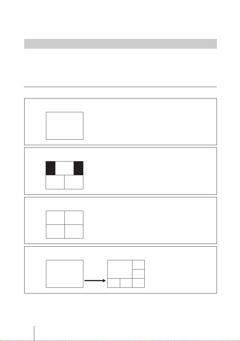
For more information about multiple video screens, refer to “Multiple Video Screen
Layout” (p. 54).
Multiple Video Screen Layout
This section explains the CPN multiple video screen layout.
The number on the left of the figure shows the number of connected Endpoints.
Layouts without a number on the left are a fixed display and are not affected
by Endpoint numbers.
Normal Standard Quality (CIF or 4CIF)
Layout 1
1
Layout 3
1
2 3
Layout 4
1
3
Layout 6
12 or more
2
4
1
1
54 Conducting Multiple Video Screen Meetings
2
3
54
6
Page 55
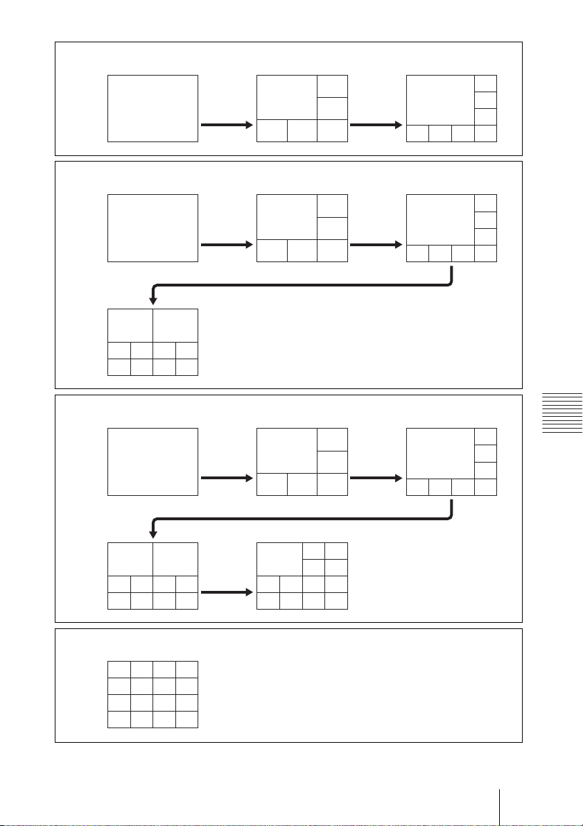
Layout 8
1 2-6 7 or more
Layout 10
12-6 7-8
1
1
1
1
2
3
54
6
2
3
54
6
21
9 or more
3456
789 10
Layout 13
12-6 7-8
1
1
2
3
54
6
2
1
3
4
8765
2
1
3
4
8765
2
1
3
Chapter 5: Using Meetings (Application)
4
8765
9-10 11 or more
21
3456
789 10
Layout 16
12
56
34
78
9 10 11 12
13 14
15 16
23
1
45
6789
10 11 12 13
55Conducting Multiple Video Screen Meetings
Page 56
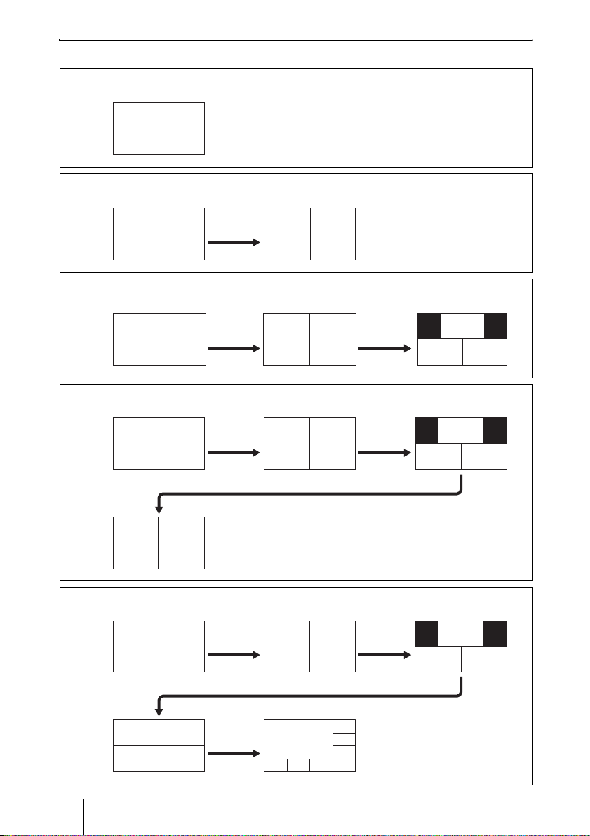
HD Quality (W432P or HD 720p)
Layout 1
1
Layout 2
12 or more
Layout 3
1 2 3 or more
1
1
2
1 1 2
2 3
Layout 4
12 3
1
1 2
2 3
4 or more
1 2
3 4
Layout 8
1
1
12 3
1 1 2
2 3
1
3
5 or more4
2
1
4
2
3
4
8765
56 Conducting Multiple Video Screen Meetings
1
Page 57
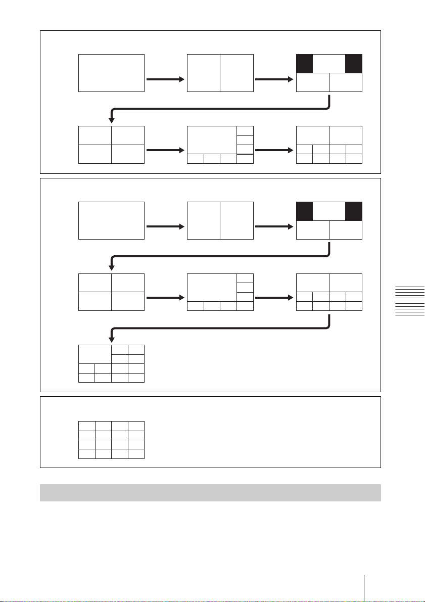
Layout 10
12 3
1 1 2
4 9 or more5-8
1
3
Layout 13
12 3
45-8
1
3
11
or more
1
2
4
1 1 2
2
4
2
3
4
12
5
8
9
13
76
1110
1
1
2
3
4
8765
2
9-10
3
4
8765
2 3
1 2
2 3
1 2
1
6543
10987
1
6543
10987
Chapter 5: Using Meetings (Application)
Layout 16
1234
5678
9 10 11 12
13 14 15 16
Upstream Resolution from Endpoints
Upstream resolution from endpoints is automatically determined so that the
image covers the largest pane in the specified multiple screen layout, without
having to expand the image.
57Conducting Multiple Video Screen Meetings
Page 58

Chapter 6: Using the Reservation System
About the Reservation System
This function, which enables general Users to make Meeting reservations, is
included with the HD VISUAL COMMUNICATION SERVER.
It is necessary for the administrator to configure the reservation system and
prepare a reservation template in advance.
Based on the reservation template, general Users designate the conference
room name, participants and usage time, and then make the meeting
reservation. In addition, Users making the reservation can notify participants
about the meeting reservation.
The Meeting attributes designated by the Template, such as the maximum
number of participants, bandwidth usage, video codec, etc., cannot be changed
by general Users.
58 About the Reservation System
Page 59

Configuring the Reservation System
Methods to configure the Reservation System will now be explained.
In order for general Users to use the Meeting Reservation function, it is
necessary first for administrators to configure the Reservation System, such as
designating the mail server to be used for providing email notifications.
1 Login to VC ONLINE (http://[HD VISUAL COMMUNICATION
SERVER address]:8080/) using an account with administrator privileges.
2 Click on [Network Config] from the [Server] menu.
The [Network Config] screen will be displayed.
3 Enter information into the configuration fields, and click the [Update]
button.
[Network Config] Screen
Setting Category Description
SMTP Server Enter the IP Address of the SMTP server for sending email
SMTP Port Specify a SMTP server port for sending email notifications.
Reservation Email
Address
Subject Enter a subject line for e-mail notifications.
Reservation Interval Select the required interval to specify the duration of a reserved
Login ID Designate authentication ID if required by your SMTP server.
Password Designate a password for the authentication ID set above.
MD5 Realm Designate MD5 Realm when your SMTP server is configured
notifications.
A SMTP Server is not included with the HD VISUAL
COMMUNICATION SERVER and should be arranged
separately.
Enter a default e-mail address.
To be used if no e-mail address is configured in the User
Account of the User reserving the Meeting.
This will be displayed as the default subject line in the enter
field when reserving a meeting. General users can change the
e-mail subject line when reserving a Meeting.
Meeting. The interval can be selected from: 1, 5, 10, 15, 20, 30
or 60 minutes.
If left blank, this function will operate “Without
Authentication”.
by the authentication type “DIGEST-MD5”.
Designate the MD5 Realm configured with your SMTP server.
Chapter 6: Using the Reservation System
59Configuring the Reservation System
Page 60

Creating a Reservation Template
Methods to create templates for Meeting Reservations will now be explained.
1 Login to VC ONLINE (http://[HD VISUAL COMMUNICATION
SERVER address]:8080/) using an account with administrator privileges.
2 Click on [Reservation] from the [Meeting] menu.
The [Reservation] screen will be displayed.
3 Click the [Add Template] button.
The [Reservation Template] screen will be displayed.
4 As with a Normal Meeting, configure settings for “Basic Information”,
“Audio”, “Video”, etc.
Hints
• By checking [Mail As Schedule], an iCalendar-format file will be attached to an email when sending a Meeting reservation confirmation e-mail.
• The [Access Control Filter] can be set, but there is no option to enter the Users
allowed to enter the Meeting.
For information about settings, please refer to “[Add Meeting] Screen” (p.
24).
5 Click the [Save] button.
The entered template information will be saved.
60 Creating a Reservation Template
Page 61

Reserving a Meeting
Methods for general Users to reserve a Meeting will now be explained.
1 Login to VC ONLINE “http://[HD VISUAL COMMUNICATION
SERVER address]:8080/” with a general user account.
2 Click on the [Reservation] menu.
The [Reservation] screen will be displayed.
3 Select the desired template, and click the grey icon inside the date box for
the date you wish to reserve the Meeting.
The Reservation input screen will be displayed.
4 Set the [Meeting Name], [Start Time] and [End Time], and select the
required User or Group from the Access List.
Set other items as necessary.
For information about Meeting Reservation settings, please refer to
“[Reservation] Screen” (p. 62).
5 Click the [Add] button.
When the Meeting Reservation is complete, the e-mail confirmation
configuration screen will be displayed.
Notes
• Meetings can be reserved in advance for up to 1 year.
• Set Reservation System in advance to enable e-mail confirmation.
• If a user or group that you specified is already scheduled to participate in another
meeting that coincides with the specified reservation time, a warning message
appears. However, you can click the [OK] button in the warning message and still
reserve the meeting.
Chapter 6: Using the Reservation System
6 Confirm the details of the [Subject] and [Mail Text] fields.
Check [Mail As Schedule] if you want to attach an iCalendar-format file to
an e-mail.
7 To send an e-mail, select the recipients from the User list, and click the
[Send Mail] button. If you do not wish to send a notification e-mail, click
the [Don’t Send Mail] button.
By clicking on the [Send Mail] button, a mail will be sent to the required
recipients.
Notes
• The e-mail address used is the address configured in the recipient’s User Information.
This e-mail address must be configured in User Information prior to configuring the
Meeting in order to send mail to the selected users.
61Reserving a Meeting
Page 62

• The reserved Meeting will not appear on the [Monitor (Meeting)] Meeting list until
the scheduled start time.
[Reservation] Screen
Setting Category Description
Meeting Name Enter the Meeting Name.
Repeat Mode Select whether to repeat a Scheduled Meeting.
Date Displays the date the Meeting is scheduled to start.
Start Time Sets Meeting Start Times on a daily basis.
End Time Sets Meeting End Times on a daily basis.
CPN Layout
Number
Share Phone Book Select whether to display in the Share Phone Book the Meeting
Owner The name of the logged-in User is displayed. This cannot be
Template Name The name of the reservation template being used is displayed.
It is not possible to duplicate Meeting Names. If a duplicated
Meeting Name is designated, the file name is automatically
updated with a number attached to the end of the name, such as
“(1)”.
• NO: Meeting is not repeated
• DA ILY: Meeting is held at the same time every day.
• WEEKLY: Meeting is repeated on the same day and time
every week.
• MONTHLY: Meeting is repeated on the same date and time
every month.
Minute intervals can be set from 1 min to 60 mins with
[Reservation Interval] under [Network Config].
Minute intervals can be set from 1 min to 60 mins with
[Reservation Interval] under [Network Config].
If any days coincide between the start and end time, change
“this day” to “next day”.
Selects the video layout of a CPN meeting. Configuration
options differ depending on the [Video Codec] and [Video
Mode] settings. In addition, it is only possible to change to
layouts with fewer video screens than the set Reservation
Template.
information that is registered on the server.
NONE: Do not display the information in the Share Phone
Book.
H323ALIAS: Display the information in the Share Phone
Book using H.323 aliases for the Meeting contact information.
E164NUMBER: Display the information in the Share Phone
Book using E.164 numbers for the Meeting contact
information.
Note
Information on a Meeting is displayed in the Share Phone Book
only when the Meeting is available to be conducted.
edited.
This cannot be edited.
62 Reserving a Meeting
Page 63

Setting Category Description
Meeting Type Displays the name of the Meeting Type configured with the
Access Control
Filter
Fixed Position User
Selection
Access List(Group) Displays a list of Groups. Select from the list, the Group you
Access List(User) Displays a list of Users. Select from the list, the User you wish
Auto Invite By checking the checkbox, users can be automatically invited
reservation template being used. This cannot be edited.
Displays the Access Control Filter configured with the
reservation template being used. This cannot be edited.
By clicking this button, the user list will be displayed. When
holding CPN mode video conferences, the User to be displayed
in the largest of the multiple video screens can be selected from
the list.
wish to include in the Meeting.
to include in the Meeting.
Users can be narrowed down by entering the information (part
of the User Name, H.323 Alias, etc.) of the User you wish to
locate in the [Search Filter] field.
to a Meeting.
It is possible to invite participants minutes before a Meeting
begins. The actual invitation is made 40 seconds after the
designated time. For example, if the “before time” parameter is
set to 5 minutes, Auto Invite will start calling in the participants
4 minutes and 20 seconds prior to the commencement of the
meeting.
In the event that the invited participant does not respond or is
logged out, Auto Invite will retry up to 5 times at intervals 30
seconds longer than the previous interval starting from the time
of the original invitation.
First Retry: 30 seconds after original invitation
Second Retry: 60 seconds after the first retry (90 seconds
after original invitation)
Third Retry: 90 seconds after the second retry (180 seconds
after original invitation)
Fourth Retry: 120 seconds after the third retry (300 seconds
after original invitation)
Fifth Retry: 150 seconds after the fourth retry (450 seconds
after original invitation)
Chapter 6: Using the Reservation System
63Reserving a Meeting
Page 64

Verify Personal Reservation Schedules
Users can display a list of meetings that they reserved themselves and reserved
meetings that they intend to attend.
1 Login to VC ONLINE “http://[HD VISUAL COMMUNICATION
SERVER address]:8080/” with a general user account.
2 Click [Personal Schedule] from the [Meeting] menu.
The [Personal Schedule] screen appears.
Meetings that the user is scheduled to attend are displayed in yellow.
Checkboxes appear to the left of meetings that the user reserved
themselves.
Edit Reservation Settings
You can edit reservation settings in the [Personal Schedule] screen.
Note
Users can only edit the settings of meetings they reserved themselves.
1 Login to VC ONLINE “http://[HD VISUAL COMMUNICATION
SERVER address]:8080/” with a general user account.
2 Click [Personal Schedule] from the [Meeting] menu.
The [Personal Schedule] screen appears.
3 Select the checkbox of the meeting for which you want to edit settings, and
click the [Update] button at the bottom left of the screen.
The [Reservation] screen appears.
4 Edit the settings for the meeting, and click the [Update] button.
The reservation settings for the meeting are updated.
For more information about reservation settings for meetings, refer to
“[Reservation] Screen” (p. 62).
64 Reserving a Meeting
Page 65

Delete Reservations
You can cancel reservations for meetings in the [Personal Schedule] screen.
Note
Users can only cancel meetings they reserved themselves.
1 Login to VC ONLINE “http://[HD VISUAL COMMUNICATION
SERVER address]:8080/” with a general user account.
2 Click [Personal Schedule] from the [Meeting] menu.
The [Personal Schedule] screen appears.
3 Clear the checkbox of the meeting you want to cancel, and click the
[Delete] button at the bottom left of the screen.
4 Click [OK] when the confirmation screen appears.
Chapter 6: Using the Reservation System
65Reserving a Meeting
Page 66

Deleting a Completed Meeting
Methods to delete a completed Meeting will now be explained.
Reserved Meeting information is not deleted automatically so delete as
necessary.
Note
VC ONLINE displays may become slower if a large volume of completed meeting
information accumulates. Be sure to delete the information periodically.
1 Login to VC ONLINE (http://[HD VISUAL COMMUNICATION
SERVER address]:8080/) using an account with administrator privileges.
2 Click on [Reservation] from the [Meeting] menu.
The [Reservation] screen will be displayed. A [Delete Old Data] button
will appear next to any Meetings that were completed at least two days
before.
3 Click the [Delete Old Data] button.
The completed Meeting information will be deleted.
66 Deleting a Completed Meeting
Page 67

Chapter 7: Server Monitoring
Confirming HD VISUAL COMMUNICATION SERVER Status
The status of the HD VISUAL COMMUNICATION SERVER can be
confirmed by either displaying processes or referencing log files.
How to Display Processes
1 Right-click on the Server Desktop and click on [Open Terminal] from the
menu.OLM
2 When the Terminal Software opens, execute the following command.
# /usr/local/vn/bin/vnstatus
Under normal conditions, you will see the following results displayed:
cnode_mcu (pid 3870) is running...
beam (pid 3785 3766) is running...
vnncs (pid 3797) is running...
vnproxy (pid 3822 3810) is running...
vnutil (pid 3823) is running...
vnlmsvr (pid 3842) is running...
vnbms (pid 3863) is running...
vnpms (pid 3885) is running...
vngk (pid 3901) is running...
vnmcu (pid 3917) is running...
vnvnc (pid 3932) is running...
vnapi (pid 3945) is running...
Chapter 7: Server Monitoring
How to Reference the Log File
1 Right-click on the Server Desktop and click on [Open Terminal] from the
menu.
2 The Terminal Software will open so execute the following command.
cp -r /var/log/ /[Log File Save Destination]/
67Confirming HD VISUAL COMMUNICATION SERVER Status
Page 68

Command Example:
cp -r /var/log/ /media/disc
The HD VISUAL COMMUNICATION SERVER component and system log
are located in /var/log/vn. Save to external media as and when necessary.
68 Confirming HD VISUAL COMMUNICATION SERVER Status
Page 69

Chapter 8: Gatekeeper
Restricting Registrations
Configuration conditions for restricting registrations will now be explained.
By default, all Endpoints are permitted to register with the Gatekeeper,
however, certain Endpoints can be restricted from registering with the
Gatekeeper either by IP Address or E.164 number.
Restrict Registrations
1 Click on [Restriction] from the [Gatekeeper] menu.
The [Restriction] screen will be displayed.
2 Click the [Add] button from either [Restriction(IP)] or [Restriction(E164)]
panel.
The [Add Restriction] screen will be displayed.
3 Select whether to permit the Gatekeeper registration or not.
4 Click the [Add] button on the [Add Restriction] panel.
This setting is registered.
Chapter 8: Gatekeeper
[Add Restriction] Screen
Setting Category Description
Restriction ID The Restriction ID automatically allotted by the system is
Restriction Type Displayed by [Restriction(IP)] or [Restriction(E164)].
Priority Enter registered restriction information in order of priority
Permission Select whether to permit the targeted terminal’s registration
IP Address This is a required field. Only displayed if the [Restriction Type]
displayed. This cannot be edited.
This is decided by clicking the [Add] button of either
[Restriction(IP)] or [Restriction(E164)]. Editing is not
possible.
using alphanumeric characters. Restrictions with a lower value
will be prioritized.
with the Gatekeeper.
is [Restriction(IP)]. Enter the IP Address of the terminal in
question.
69Restricting Registrations
Page 70

Setting Category Description
Netmask This is a required field. Only displayed when the [Restriction
Condition Only displayed when the [Restriction Type] has been
Prefix This is a required field. Only displayed when the [Restriction
Length Enter the length of the E.164 character string.
Type] has been configured as [Restriction(IP)]. Enter the
terminal’s [IP Address], if restricting by IP Address.
configured as [Restriction(E164)]. Select the conditions
determining whether the terminal is to be permitted or not.
LESS: Indicates a [Length] shorter than the entered E.164
character string length.
EQUAL: Indicates a [Length] equal to the entered E.164
character string length.
GREATER: Indicates a [Length] longer than the entered
E.164 character string length.
Type] has been configured as [Restriction(E164)]. Enter a
prefix to be shared from the E.164 Number of the terminal in
question.
70 Restricting Registrations
Page 71

Edit Registration Restrictions
1 Click on [Restriction] from the [Gatekeeper] menu.
The [Restriction] screen will be displayed.
2 Select the restriction information you want to edit from [Restriction (IP)]
or [Restriction (E164)], and click the [Change] button.
The [Edit Restriction] screen will be displayed.
3 Select whether to permit the Gatekeeper registration or not.
For more information about setup procedures, refer to “[Add Restriction]
Screen” (p. 69).
4 Click the [Add] button on the [Edit Restriction] panel.
The edited information will override previous information and be saved.
Delete Restriction Information
1 Click on [Restriction] from the [Gatekeeper] menu.
The [Restriction] screen will be displayed.
2 Select the restriction information you want to delete from [Restriction (IP)]
or [Restriction (E164)], and click the [Delete] button.
The selected registration information will be deleted.
Chapter 8: Gatekeeper
71Restricting Registrations
Page 72

Chapter 9: VCMP Servers
About VCMP Servers
A VCMP server is a media processing server used for screen-exchange
processing during meetings and screen-layout composition during CPN
meetings.
By using a VCMP server in conjunction with the HD VISUAL
COMMUNICATION SERVER, you can disperse the processing load for
encoding and increase the number of meetings that can be conducted at one
time.
For more information on setting up a VCMP server, consult your local dealer.
72 About VCMP Servers
Page 73

Registering VCMP Servers
After setting up the VCMP server, register the VCMP server information in
VC ONLINE.
This section describes how to register and edit the VCMP server information.
Register VCMP Server Information
1 Login to VC ONLINE (http://[HD VISUAL COMMUNICATION
SERVER address]:8080/) using an account with administrator privileges.
2 Click on [Media Processor] from the [Server] menu.
The [Media Processor] screen will be displayed.
3 Click the [Add] button.
The [Add VCMP Server] screen will be displayed.
4 Enter the [VCMP Server Type], [VCMP Server Display Type], [VCMP
Server Hostname (FQDN)], and [Capacity], and then click [Add].
If you set up multiple VCMP servers, be sure to register all the VCMP
servers.
5 Restart the VCMP server.
6 Restart the HD VISUAL COMMUNICATION SERVER.
The VCMP server is registered to the HD VISUAL COMMUNICATION
SERVER.
Note
Always turn on the VCMP server before the HD VISUAL COMMUNICATION
SERVER.
[Add VCMP Server] Screen
Setting Category Description
VCMP Server ID Depending on the system, this displays the automatically indexed
VCMP Server
Typ e
VCMP Server
Display Type
VCMP Server
Hostname
(FQDN)
Capacity Enter the maximum number of users that can connect to the
ID of the VCMP server. This cannot be modified.
Select whether the VCMP server is a master or slave.
Enter the name of the VCMP server.
Enter the hostname of the VCMP server.
VCMP server.
Chapter 9: VCMP Servers
73Registering VCMP Servers
Page 74

Setting Category Description
Default Master This software does not support this function.
Alt Master This software does not support this function.
Edit VCMP Server Information
1 Login to VC ONLINE (http://[HD VISUAL COMMUNICATION
SERVER address]:8080/) using an account with administrator privileges.
2 Click on [Media Processor] from the [Server] menu.
The [Media Processor] screen will be displayed.
3 Click the [Edit] button.
The [Edit VCMP Server] screen will be displayed.
4 Make the necessary changes, and click [Edit].
For information on setting each item, refer to “[Add VCMP Server]
Screen” (p. 73).
5 Restart the VCMP server.
6 Restart the HD VISUAL COMMUNICATION SERVER.
The VCMP server information registered on the HD VISUAL
COMMUNICATION SERVER is updated.
Note
Always turn on the VCMP server before the HD VISUAL COMMUNICATION
SERVER.
74 Registering VCMP Servers
Page 75

Chapter 10: Additional Configuration
ARQ (Automatic Repeat ReQuest) Function
When video or H.239 packet loss occurs during transmissions, this function
automatically requests the transmitter to resend the packet. Audio packets are
not supported with this function.
This is a simplified version of the Real-Time ARQ function used on the PCS
series.
Configuration is not necessary to enable this function, and resend requests are
performed automatically.
Depending on the operating environment, this function may not be as effective
as when it is used between PCS-series units.
Chapter 10: Additional Configuration
75ARQ (Automatic Repeat ReQuest) Function
Page 76

Configuring Personal Information
Methods to configure Users’ personal information will now be explained.
Login to VC ONLINE, and click on [Personal] from the [User] menu. The
[Personal] screen will be displayed, allowing changes to be made to the
personal information of the logged in User.
[Personal] Screen
Setting Category Description
Password Password the user originally registered.
Last Name User’s last name that is displayed in the [Member List] on the
Middle Name User’s middle name that is displayed in the [Member List] on the
First Name User’s first name that is displayed in the [Member List] on the
e-mail User’s e-mail address.
IP Address Enter if the terminal that will be used by the user has been
FT Connection Select the Firewall Traversal setting.
FT Tunnel Type Select the tunnel type for Firewall Traversal. Configure this only
Set Select the checkbox to enable the [Action], [Forwarding Type],
communications screen.
communications screen.
communications screen.
assigned a fixed IP address.
Autodetect FT: Automatically determine whether Firewall
Traversal is necessary when connecting to the HD VISUAL
COMMUNICATION SERVER, and connect via the FT personal
client only if necessary.
Autodetect GC: Automatically determine whether Firewall
Traversal is necessary when connecting to the HD VISUAL
COMMUNICATION SERVER, and connect via the FT group
client only if necessary.
Use FT: Always use the FT personal client when connecting to
the HD VISUAL COMMUNICATION SERVER.
Use GC: Always use the FT group client when connecting to the
HD VISUAL COMMUNICATION SERVER.
NONE: Connect without using Firewall Traversal.
Note
FT personal clients can only be used from a PC Endpoint terminal.
Therefore, [Autodetect FT] and [Use FT] cannot be used from an
H.323 terminal.
when using Firewall Traversal.
NONE: Do not specify a tunnel type.
TCP: Connect using a TCP tunnel.
UDP: Connect using a UDP tunnel.
and [Forwarding Destination] settings. This can be configured for
each [Condition].
76 Configuring Personal Information
Page 77

Setting Category Description
Condition Indicates the status; [Busy], [Online] (User can be called), or
Action Select the [Confirm], [Reject] or [Forward] Action when
Forwarding Type Select forwarding destination type when selecting [Forward] as
[Offline] (User cannot be called). The [Action], [Forwarding
Type], and [Forwarding Destination] settings can be configured
for each status.
answering calls.
an [Action]
H.323 Alias: When selecting a H.323 Alias as a forwarding
destination
E.164 Number: When selecting an E.164 Number as a
forwarding destination.
IP Address: When selecting an IP Address as a forwarding
destination.
Forwarding
Destination
When selecting [Forward] as an [Action], enter a forwarding
destination that complies with a type specified in the [Forwarding
Type].
Chapter 10: Additional Configuration
77Configuring Personal Information
Page 78

Sending an E-mail to other Users
Methods to send e-mail to other users will now be explained.
Notes
• It is necessary to configure the reservation system prior to sending an e-mail.
• The e-mail address used is the address configured in the recipient’s User Information.
1 Login to VC ONLINE (http://[HD VISUAL COMMUNICATION
SERVER address]:8080/) using an account with administrator privileges.
2 Click on [Send Mail] from the [User] menu.
The [Send Mail] screen will be displayed.
3 Enter [Subject] and [Mail Text], and select the e-mail recipient from
[Group] or [User].
Users can be narrowed down by entering the information (part of the User
Name, H.323 Alias, etc.) of the User you wish to locate in the [Search
Filter] field.
When sending an e-mail to all registered users, check the [All Users]
checkbox. In the event of sending an e-mail to all registered users with
administrator privileges, check the [All System Administrators] checkbox.
4 Click the [Send Mail] button.
The e-mail will be sent to all selected mail recipients.
78 Sending an E-mail to other Users
Page 79

Reporting
Reporting offers a function for reporting operational results. Reporting is used
in conjunction with the HD VISUAL COMMUNICATION SERVER.
How to Access the Reporting Function
1 Login to VC ONLINE (http://[HD VISUAL COMMUNICATION
SERVER address]:8080/) using an account with administrator privileges.
2 Click [Report] at the top right of the page.
To execute a search, click the [Search] button.
Displayed Search Information
Click [Search], and the following results are displayed.
• Call Statistics: Display of statistical information
• Call Records: Button for CSV file acquisition
• Displays list of search results
Call Statistics
Displays statistical information of search results.
Category Description
Total number of calls Total number of listed calls
Total duration (hour:min:sec) Total connection time
Average duration (hour:min:sec) Average connection time
Max duration (hour:min:sec) Maximum connection time
#Unique callers Number of calls out
#Unique call destinations Number of calls in
Chapter 10: Additional Configuration
Call Records
Download CSV Full: Gets file of all log items.
Download CSV part: Gets file of part of the log items.
79Reporting
Page 80

Search Results
Displays a record of information regarding previously completed call
connections (call information).
Category Description
# Serial number of search result
Start time Time that the call was connected
End time Time that the call was disconnected
Call compilation
code
Call destination H.323 Alias of receiving caller (connection destination)
Caller H.323 Alias of originator caller (source)
Caller’s IP
address
Call duration
(ms)
Status code
CC: Call Completed normally
CAD: Abnormal call disconnected
UCN: Unconnected due to network failure
UCI: Unconnected due to invalid address
IP Address of originator caller
Connection time
Calculated at units of ms (milliseconds)
Call information is recorded when a call ends.
Information for search is updated every two minutes so wait for about two
minutes to conduct a fresh search.
80 Reporting
Page 81
Sony PCS-XG/XL/XA/XC Series Firmware Update Function
The Sony PCS-XG/XL/XA/XC Series has a firmware update function.
Methods to setup and use this function will now be explained.
Setup
1 Right-click on the Server Desktop and click on [Open Terminal] from the
menu.
2 The Terminal Software will then open so execute the following command.
# cd /usr/local/vn
# mkdir sony
A directory entitled “sony” will be created under the HD VISUAL
COMMUNICATION SERVER’s /usr/local/vn directory.
3 Copy the Sony PCS-XG/XL/XA/XC Series firmware to the sony directory.
Firmware Update Procedure
Notes
• When updating PCS-XG/XL/XA/XC Series firmware, execute [Update Firmware]
after checking whether the terminal power is set to ON and is not currently being used.
• Do not turn the power OFF when updating PCS-XG/XL/XA/XC Series firmware
under any circumstances.
Chapter 10: Additional Configuration
1 Login to VC ONLINE (http://[HD VISUAL COMMUNICATION
SERVER address]:8080/) using an account with administrator privileges.
2 Click on [Endpoint] from the [Monitor] menu.
The [Monitor (Endpoint)] screen will be displayed.
3 Click [Update Firmware] at the bottom left of the screen.
4 Select the checkbox of the Sony PCS-XG/XL/XA/XC Series terminal you
want to update.
Note
You can only update one terminal at a time.
81Sony PCS-XG/XL/XA/XC Series Firmware Update Function
Page 82

5 Select the firmware to be updated from the [Select Firmware Update File]
pull-down menu, and click the [Update Firmware] button.
The confirmation screen will be displayed.
6 Confirm the details of the confirmation screen, and execute [Update
Firmware].
Status Display
When the Sony PCS-XG/XL/XA/XC Series firmware update is executed,
firmware update and update completion status are displayed.
Status Column Description
Blank Initial firmware update execution screen
Updating The firmware update is being executed
Upload was
completed
normally
Status Error!
Communicating
java.net.Connect
Exception:
Connection
refused
Confirms completion of update. However, it is displayed when
the firmware file has been forwarded.
An error displayed when update is executed while Sony PCS-XG/
XL/XA/XC Series is busy.
Error when connection could not be completed. It is displayed for
errors arising from executions routed through PCS-FT.
82 Sony PCS-XG/XL/XA/XC Series Firmware Update Function
Page 83

Linking to the HD RECORDING SERVER
You can record meeting using the HD RECORDING SERVER.
By configuring the following settings and specifying an HD RECORDING
SERVER while making a reservation for a meeting, you can have recording
start automatically when the meeting starts.
For more information on HD RECORDING SERVER operations and
functions, refer to the operating instructions for the HD RECORDING
SERVER.
Configure the HD RECORDING SERVER Link
1 Login to VC ONLINE (http://[HD VISUAL COMMUNICATION
SERVER address]:8080/) using an account with administrator privileges.
2 Click on [Recording Servers] from the [Server] menu.
The [Recording Servers] screen appears.
3 Click the [Add] button.
The [Add Recording Server] screen appears.
4 Configure each setting.
For information on setting each item, refer to “[Add Recording Server]
Screen” (p. 83).
5 Click the [Add] button when you are finished configuring the settings.
A confirmation dialog box appears.
6 Click [OK].
The recording server is registered with the configured settings.
Note
The HD VISUAL COMMUNICATION SERVER must be restarted after the
settings are configured.
[Add Recording Server] Screen
Category Description
Recording Server IDNumber used to identify the recording server. This is
Recording Server
Name
automatically assigned by the system during registration.
This cannot be manually specified or modified.
Required field.
Specify the name of the recording server.
Chapter 10: Additional Configuration
83Linking to the HD RECORDING SERVER
Page 84

Category Description
Address Required field.
H.323 Alias Required field.
E.164 Number Specify the E.164 number of the recording server. Specify the
Capacity Maximum connection capacity of the HD RECORDING
Specify the IP address of the recording server.
Specify the H.323 alias of the recording server. Specify the first
H.323 alias in the list of H.323 aliases (clotho.rs.h323.aliases)
registered in the HD RECORDING SERVER settings
(vnrs.conf).
first E.164 number in the list of E.164 numbers
(clotho.rs.e164.numbers) registered in the HD RECORDING
SERVER settings (vnrs.conf).
SERVER. The default setting is 5.
84 Linking to the HD RECORDING SERVER
Page 85

Appendix
List of Terms
Terms used in this Document and the HD VISUAL COMMUNICATION
SERVER document will now be explained.
HD VISUAL COMMUNICATION SERVER
HD VISUAL COMMUNICATION ONLINE
A portal site provided by the HD VISUAL COMMUNICATION SERVER.
A website that enables easy login to the HD VISUAL COMMUNICATION
SERVER and its online help function can be displayed from this site.
HD VISUAL COMMUNICATION SERVER
This is a server that enables video conferences between remote locations.
Its components include Gatekeeper, H.323MCU and Web Service.
User
PC Endpoint
PC Endpoint is H.323 client software to be installed on a computer.
This software operates on Windows.
Chairman
Moderated meetings may be assigned a Chairman to control the meeting.
The Chairman controls audio and video selection as well as data functions during
a Moderated Meeting. The Chairman is also able to manage requests to speak from
the participants.
General User
Users who receive audio and visual content during Moderated Meetings. They can
seek permission from the Chairman to speak during a Moderated Meeting.
System Administrator
A User that can perform HD VISUAL COMMUNICATION SERVER system
administration.
An Administrator account is created by default when the HD VISUAL
COMMUNICATION SERVER system is installed.
Users can register to have administrator privileges as and when necessary.
User
A User refers to all HD VISUAL COMMUNICATION SERVER users.
Appendix
85List of Terms
Page 86

Meetings
Meetings
Meetings provide a virtual space to conduct audio, video and data communication.
They can be likened to virtual conference system “Conference Rooms”.
Meetings can be created, edited and deleted by System Administrators.
As well as being a style of communication, Meetings can be categorized by the 2
methods by which they control audio and video distribution.
•Normal
• Presentation
Moderated Meetings
A meeting with an assigned Chairman. The Chairman controls video and audio
distribution
Presenting
This mode is a Moderated Meeting during which the Chairman can give a one-way
presentation to other participants. In this mode, General Users may request
permission to speak, however, they cannot speak until permission has been granted
by the Chairman.
Open Forum
Status of a Moderated Meeting in which a General User has been granted
permission to address all Meeting participants by the Chairman. Under this status,
the General User for whom permission to speak has been granted can speak to all
Meeting participants in a fashion similar to the Meeting Chairman.
The Chairman can continue the Meeting in this status, or switch to any other
desired mode.
General Users may request permission to speak, however, they will not be able to
speak until permission has been granted by the Chairman.
Side Meeting
Status of a Moderated Meeting in which a General User has been granted
permission to speak to the Chairman. It reverts to this Mode as soon as the
permission is granted. Under this status, only the general User and the Chairman
may converse with each other. The audio for other general Users will be disabled.
The Chairman can continue the Meeting in this status, or switch to any other
desired mode.
General Users may request permission to speak; however, they will not be able to
speak until permission has been granted by the Chairman.
Lecture
This mode is a Moderated Meeting in which the Chairman and the General Users
receive images in different screen layouts.
This mode has two states: one in which only the Chairman can be heard, and one
in which the Chairman and a General User that the Chairman grants permission to
speak can be heard.
General Users can request permission to speak, but cannot be heard until
permission is granted.
86 List of Terms
Page 87

In the state where only the Chairman can be heard, each General User appears on
the Chairman’s screen, while only the Chairman appears on the General User
screens.
In a state where a General User has been granted permission to speak, each General
User appears on the Chairman’s screen with priority on the speaker, while only the
Chairman and the speaker appear on the General User screens.
Presentation Meeting
Audio and video are controlled by Users.
This type of meeting includes Moderated Meetings.
Normal Meeting
All Meeting participants have the same right to speak in a Meeting. HD VISUAL
COMMUNICATION SERVER controls all audio and video broadcasts according
to the attributes configured for the Meeting.
CPN
A multiple video screen function (Continuous Presence) that allows video streams
from meeting participants to be mixed and transmitted to all participants. A
maximum of 16 video streams can be mixed at once.
Standards
Appendix
E.164
An ITU-T (International Telecommunication Union) E series recommendation,
representing a numbering plan for international electronic communications. An
E.164 number uniquely identifies a public network termination point and typically
consists of three fields, CC (country code), NDC (national destination code), and
SN (subscriber number), up to 15 digits in total. This can be thought of as a Service
number.
H.323
An ITU-T “umbrella” of standards for Packet-based multimedia communications
systems. This standard defines the different multimedia entities that make up a
multimedia system - Endpoints, Gateways, Multipoint Conferencing Units
(MCUs), and Gatekeepers -- and their interaction over an IP-based network.
H.323 Alias
An identifier (name) for a terminal, User or Meeting using H.323 protocol. When
conducting video conferencing using H.323 protocol, values identifying terminals,
users or Meetings are assigned. However, these values are extremely difficult for
humans to remember so a separate name (alias) represented by a character string is
also assigned. This can be thought of as a Service number.
ITU-T (International Telecommunication Union Telecommunication
Standardization Sector)
A sub-organization of the International Telecommunication Union (ITU), serving
as the standardization sector for electronic communications. It is the development
body for international standards related to telecommunications.
87List of Terms
Page 88

Other
H.239
H.239 is an ITU-T recommendation from the H.32x Multimedia Communications’
macrofamily of standards for multimedia communications over various networks.
It enables data, such as computer or video presentation materials to be transmitted
together with a video conference session.
Smtp Server
Server used to send e-mail.
88 List of Terms
Page 89
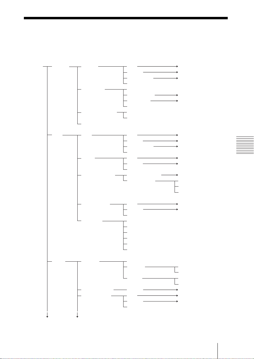
Menu Components
This software is composed of the following menus.
* These Menus, Setting Categories and Selection Options are not supported by this
software.
Top Page Meeting Meeting Add ABCDE
Change ABCDE
Add by Copy ABCDE
Delete
Reservation Timezone
Add Template F
Reservation G
Delete Old Data
Personal Schedule Update
Delete
Display Schedule
User User Add H
Change H
Add by Copy H
Delete
Group Add I
Change I
Delete
Personal Account Personal Account J
Edit Contacts* Search and Add Contacts
Add Contact Group
Add Contact
Appendix
User Template Add K
Change K
Delete
Send Mail Subject
Mail Text
All User
All System Administrators
Users
Groups
Server Licenses License Numbers
Licenses Add License*
Activate License*
Tokens Delete Token*
Meeting Server* Change L
Server Setting* Add M
Change M
Delete
The following pageThe following page
Add PreAssigned License*
89Menu Components
Page 90

Network Config SMTP Server
SMTP port
Reservation Email Address
Subject
Reservation Interval
Login ID
Password
MD5 Realm
Firewall Traversal FT Servers Add N
Change N
Delete
admin
FT Group Clients Add O
Change O
Delete
Media Processor Add P
Change P
Recording Servers Add Q
Update Q
Delete
LDAP Config* Add R
Telnet* List New S
Select Command File
Execute
Delete
Result
Monitor Endpoint Detail
Delete Registration
Call to Meeting
Select Meeting Call to Meeting / Cancel
Update Firmware
Meeting Lock
Free
Withdraw All
Input IP Address
Call to Meeting
Member List Hangup / Close
Select EP Call to Meeting / Cancel
Call Detail
Input Meeting ID / Input H.323 Alias / Input E.164 Number
Input User ID / Input H.323 Alias / Input E.164 Number
1 / 5 / 10 / 15 / 20 / 30 / 60
/
The following pageThe following page
90 Menu Components
Page 91

Control Panel Hangup
Permit Speaking
Prohibit Speaking
Call By List Add User to Meeting
Call
Call By Input Input User ID /
Input H.323 Alias /
Input E.164 Number
Call
Change Mode
Presenting
Change LC Change LC
Change
Change VS Audio / Time / Chairman
Change VS
Update Now
GateKeeper Neighbor GK* Add T
Change T
Delete
Gateway* Add U
Change U
Delete
Restriction Restriction(IP) Add V
Change V
Delete
Restriction(E164) Add W
Change W
Delete
Name Resolution* Add X
Change X
Delete
Change CPN Layout Number
Open forum / Side Meeting /
1 / 2 / 3 / 4 / 8 / 10 / 13 / 16
Appendix
Download Documents Software License Agreements
Operating Instructions
Log*
Report
Statistics*
Help
91Menu Components
Page 92

A
B
C
Add/Edit Meeting Meeting ID
Basic Meeting Name
H.323 Alias
E.164 Number
Max Members
Meeting Type Normal / Loopback / Moderated
Meeting Mode
Operator Mode Disable / MIC OFF / MIC ON
Bandwidth Control STATIC / DYNAMIC
Max Bandwidth(conf)
Max Bandwidth(ep)
Audio Codec G.711 u-law / G.711 A-law / G.722 /
MPEG4-AAC-LC / Auto
Video Enable / Disable
CPN ON / OFF
Video Codec H.261 / H.263 / H.263+ / H.264 /
H.264 High Profile / H.264 Auto
Resolution
Video Switch Mode Audio / Time / Chairman
CPN Layout Number 1 / 2 / 3 / 4 / 6 / 8 / 10 / 13 / 16
H.239 ON / OFF
H.239 Bandwidth
H.239 Codec H.263+ / H.264
H.239 Resolution XGA / HD 720p / HD 1080p
Application Sharing ON / OFF
Application Sharing Bandwidth
Add/Edit Meeting Activate ALWAYS / CLOSED / SCHEDULED
Detail Repeat Mode NO / DAILY / WEEKLY / MONTHLY
Date
Start Time [hour] 00-23
[min]
45 / 50 / 55
End Time this day / next day
[hour] 00-23
[min]
45 / 50 / 55
ISC ON / OFF
Time
Change
Far End Camera Control ON / OFF
Share Phone Book NONE / H323ALIAS / E164NUMBER
Encryption NONE / ENCRYPTION / CONNECTIVITY
Template Mode
Audio Latency 2 / 3 / 4 / 5 / 6 / 7 / 8 / 9 / 10
Audio Gain Control ON / OFF
W432P ON / OFF
CIF1 ON / OFF
CIF2 ON / OFF
Add/Edit Meeting Access Control Filter
Access
SERVERCALL
Access List(Group)
Access List(User)
Template ID
Open Forum / Side Meeting / Presenting / Lecture
CIF / 4CIF / W432P / HD 720p / HD 1080p
00 / 05 / 10 / 15 / 20 / 25 / 30 / 35 / 40 /
00 / 05 / 10 / 15 / 20 / 25 / 30 / 35 / 40 /
NONE / IPADDRESS / H323ALIAS /H323ALIAS_IP /
92 Menu Components
Page 93

D
E
F
Add/Edit Meeting Chairman
Presenter
Add/Edit Meeting VCMP Server
VCMP Fixed Position User
Reservation Template Meeting ID
Meeting Name
Max Members
Meeting Type Normal / Loopback / Moderated
Meeting Mode
Operator Mode NONE / MIC OFF / MIC ON
Bandwidth Control STATIC / DYNAMIC
Max Bandwidth(conf)
Max Bandwidth(ep)
ISC ON / OFF
Time
Change
Access Control Filter NONE / IPADDRESS / H323ALIAS /
H323ALIAS_IP / SERVERCALL
Share Phone Book NONE / H323ALIAS / E164NUMBER
Encryption NONE / ENCRYPTION / CONNECTIVITY
Mail As Schedule
Auto Invite [min] 0-10
Audio Codec G.711 u-law / G.711 A-law / G.722 /
MPEG4-AAC-LC / Auto
Audio Latency 2 / 3 / 4 / 5 / 6 / 7 / 8 / 9 / 10
Audio Gain Control ON / OFF
Video Enable / Disable
CPN ON / OFF
Video Codec H.261 / H.263 / H.263+ / H.264 /
H.264 High Profile / H.264 Auto
Resolution
Video Switch Mode Audio / Time / Chairman
CPN Layout Number 1 / 2 / 3 / 4 / 6 / 8 / 10 / 13 / 16
VCMP Server localhost
W432P ON / OFF
CIF1 ON / OFF
CIF2 ON / OFF
H.239 ON / OFF
H.239 Bandwidth
H.239 Codec H.263+ / H.264
H.239 Resolution XGA / HD 720p / HD 1080p
Application Sharing ON / OFF
Application Sharing Bandwidth
Open Forum / Side Meeting / Presenting / Lecture
CIF / 4CIF / W432P / HD 720p / HD 1080p
Appendix
93Menu Components
Page 94

G
H
Reservation Meeting Name
Repeat Mode NO / DAILY / WEEKLY / MONTHLY
Date
Start Time [hour] 00-23
[min] 00 / 05 / 10 / 15 / 20 / 25 / 30 / 35 / 40 /
45 / 50 / 55
End Time this day / next day
[hour] 00-23
[min] 00 / 05 / 10 / 15 / 20 / 25 / 30 / 35 / 40 /
45 / 50 / 55
CPN Layout Number
Share Phone Book NONE / H323ALIAS / E164NUMBER
Owner
Template Name
Meeting Type
Access Control Filter
Fixed Position User Selection
Access List (Group)
Access List (User)
Auto Invite [min] 0-10
Add/Edit User User ID
User Type PCEP / H.323 / FT Client / SIP*
Login Name
Password
H.323 Alias
E.164 Number
User Template
Share Phone Book NONE / H323ALIAS / E164NUMBER /
IPADDRESS
First Name
Middle Name
Last Name
e-mail
IP Address
Administrator
Basic Max Bandwidth
Application Sharing Bandwidth
Bandwidth
Setting of
PCEP Profile
FT Autodetect FT / Autodetect GC /
Connection Use FT / Use GC / NONE
FT NONE / TCP / UDP
Tunnel Type
Forwarding Busy [Action] Confirm / Reject / Forward
[Forwarding Type] H.323 Alias /
E.164 Number / IP Address
Online [Action] Confirm / Reject / Forward
[Forwarding Type] H.323 Alias /
E.164 Number / IP Address
Offline [Action] Confirm / Reject / Forward
[Forwarding Type] H.323 Alias /
E.164 Number / IP Address
DISABLE / ENABLE
94 Menu Components
Page 95

I
J
K
L
Add/Edit Group Group ID
Group Name
Subordinate Group
Subordinate User
Personal User ID
User Type
Login Name
Password
H.323 Alias
E.164 Number
User Template
Max Bandwidth
Application Sharing Bandwidth
Bandwidth Setting of DISABLE / ENABLE
PCEP Profile
First Name
Middle Name
Last Name
e-mail
IP Address
Administrator
FT Connection Autodetect FT / Autodetect GC / Use FT /
Use GC / NONE
FT Tunnel Type NONE / TCP / UDP
Busy [Action] Confirm / Reject / Forward
[Forwarding Type] H.323 Alias / E.164 Number /
IP Address
Online [Action] Confirm / Reject / Forward
[Forwarding Type] H.323 Alias / E.164 Number /
IP Address
Offline [Action] Confirm / Reject / Forward
[Forwarding Type] H.323 Alias / E.164 Number /
IP Address
Add/Edit User Template Template ID
Template Name
Max Bandwidth
Application Sharing Bandwidth
Bandwidth Setting of DISABLE / ENABLE
PCEP Profile
FT Connection Autodetect FT / Autodetect GC / Use FT /
Use GC / NONE
FT Tunnel Type NONE / TCP / UDP
Edit Server* Server ID
Server Name
Server Type
Server Address
Max Call
Appendix
95Menu Components
Page 96

Add/Edit Server Setting* Key
M
N
O
P
Q
R
Val u e
Enable
Name(English)
Description(English)
Name(Japanese)
Description(Japanese)
Add/Edit FT Server FT Server ID
FT Server Name
Display Name
IP Address
Port
Admin Web Port
Add/Edit FT Group Client
FT Group Client Name
Display Name
IP Address
FT Server1
FT Server2
Add/Edit VCMP Server VCMP Server ID
VCMP Server Type
VCMP Server Display Type
VCMP Server Hostname(FQDN)
Capacity
Default Master
Alt Master
Add/Edit Recording Recording Server ID
Servers Recording Server Name
Address
H.323 Alias
E.164 Number
Capacity
Add LDAP Config* LDAP ID
LDAP Server Address
Server Type OpenLDAP / Active Directory / Others
Port
Root DN
Password
suffix
filter
User Template
Login Name
H.323 Alias
E.164 Number
IP Address
First Name
Middle Name
Last Name
e-mail
FT Group Client ID
96 Menu Components
Page 97

S
T
U
V
W
X
Add Command File* File Name
Command
Add/Edit Neighbor GK* Neighbor Gate Keeper ID
IP Address
Port
Prefix
Priority
Gate Keeper ID
Add/Edit Gateway* Gateway ID
Gateway Name
H.323 Alias
E.164 Number
IP Address
Max Call
Prefix Add Prefix
Rewrite
Priority
Length
Edit Prefix
Rewrite
Priority
Length
Forwarding Busy [Action] Confirm / Reject / Forward
[Forwarding Type] H.323 Alias /
E.164 Number / IP Address
Online [Action] Confirm / Reject / Forward
[Forwarding Type] H.323 Alias /
E.164 Number / IP Address
Offline [Action] Confirm / Reject / Forward
[Forwarding Type] H.323 Alias /
E.164 Number / IP Address
Add/Edit Restriction(IP)
Restriction Type
Priority
Permission permit / not permit
IP Address
Netmask
Add/Edit Restriction Restriction ID
(E.164) Restriction Type
Priority
Permission permit / not permit
Condition LESS / EQUAL / GREATER
Prefix
Length
Restriction ID
Appendix
Add/Edit Name Resolution*
Display Name
File Name
Priority
enable
Name Resolution ID
97Menu Components
Page 98

S
ony Corporation
 Loading...