

Page 1

PCS-6000/6000P
3-205-382-17 (1)
Multimedia Terminal
Operating Instructions
Before operating the unit, please read this manual
thoroughly and retain it for future reference.
PCS-6000/6000P
2000 Sony Corporation
Page 2

Owner’s Record
The model and the serial numbers are located at the bottom.
Record the serial number in the space provided below. Refer
to these numbers whenever you call upon your Sony dealer
regarding this product.
IMPORTANT INSTRUCTION TO USERS
1.This equipment complies with Part 68 of the FCC Rules.
On the bottom of this equipment is a label that contains,
among other information, the FCC registration number for
this equipment. If requested, this information must be
provided to the telephone company.
Model No. PCS-6000/6000P
Serial No. ______________
WARNING
To prevent fire or shock hazard, do not
expose the unit to rain or moisture.
To avoid electrical shock, do not open the
cabinet. Refer servicing to qualified
personnel only.
THIS APPARATUS MUST BE EARTHED.
For the customers in the USA
This device complies with Part 15 of the FCC Rules.
Operation is subject to the following two conditions: (1) This
device may not cause harmful interference, and (2) this
device must accept any interference received, including
interference that may cause undesired operation.
This equipment has been tested and found to comply with
the limits for a Class A digital device, pursuant to Part 15 of
the FCC Rules. These limits are designed to provide
reasonable protection against harmful interference when the
equipment is operated in a commercial environment. This
equipment generates, uses and can radiate radio frequency
energy and, if not installed and used in accordance with the
instruction manual, may cause harmful interference to radio
communications. Operation of this equipment in a residential
area is likely to cause harmful interference in which case the
user will be required to correct the interference at his own
expense.
2.If this terminal equipment causes harm to the telephone
network, the telephone company will notify you in advance
that temporary discontinuance of service may be required.
But if advance notice is not practical, the telephone
company will notify the customer as soon as possible.
Also, you will be advised of your right to file a complaint
with the FCC if you believe it is necessary.
3.The telephone company may make changes in its facilities,
equipment, operations or procedures that could affect the
operation of the equipment. If this happens the telephone
company will provide advance notice in order for you to
make necessary modifications to maintain uninterrupted
service.
4.If trouble is experienced with this equipment for repair or
warranty information, please contact Sony Business
Information Center
causing harm to the telephone network, the telephone
company may request that you disconnect this equipment
until the problem is resolved.
5.This equipment cannot be used on public coin phone
service provided by the telephone company. Connection to
party line service is subject to state tariffs.
For the Customers in EU countries
Hereby, Sony Corporation, declares that this PCS-P600P is
in compliance with the essential requirements and other
relevant provisions of Directive 1999/5/EC.
The PCS-P600P is intended to be connected to the ISDN
using basic rate access interface in accordance with CTR 3
protocol or primary rate access interface in accordance with
CTR 4 protocol.
1-800-686-7669. If the equipment is
You are cautioned that any changes or modifications not
expressly approved in this manual could void your authority
to operate this equipment.
The shielded interface cable recommended in this manual
must be used with this equipment in order to comply with the
limits for a digital device pursuant to Subpart B of Part 15 of
FCC Rules.
2
This manual focuses on using ISDN lines to conduct a
videoconference, but it also covers non-ISDN lines. If you
use ISDN lines, consult your Sony dealer for more
information.
• The ISDN service may not be available in some areas.
Page 3

Voor de klanten in Nederland
Gooi de batterij niet weg, maar lever hem in als KCA.
Raadpleeg uw leverancier indien de batterij moet worden
vervangen na langdurig of intensief gebruik. Om
kortsluiting en elektrocutie te voorkomen, mag de batterij
alleen worden verwijderd en vervangen door vakbekwaam
servicepersoneel.
If you dispose the unit, consult your nearest Sony Service
Center. The built-in battery must be treated as a chemical
waste.
For the customers in Canada
This Class A digital apparatus complies with Canadian ICES-
003.
NOTICE: The Industry Canada label identifies certified
equipment. This certification means that the equipment
meets certain telecommunications network protective,
operational and safety requirements as prescribed in the
appropriate Terminal Equipment Technical Requirements
document (s). The Department does not guarantee the
equipment will operate to the user’s satisfaction.
Before installing this equipment, users should ensure that it
is permissible to be connected to the facilities of the local
telecommunications company. The equipment must also be
installed using an acceptable method of connection. The
customer should be aware that compliance with the above
conditions may not prevent degradation of service in some
situations.
Repairs to certified equipment should be made by an
authorized Canadian maintenance facility designated by the
supplier. Any repairs or alterations made by the user to this
equipment, or equipment malfunctions, may give the
telecommunications company cause to request the user to
disconnect the equipment.
Users should ensure for their own protection that the
electrical ground connections of the power utility, telephone
lines and internal metallic water pipe system, if present, are
connected together. This precaution may be particularly
important in rural areas.
Caution: Users should not attempt to make such
connections themselves, but should contact the appropriate
electric inspection authority, or electrician, as appropriate.
3
Page 4

Table of Contents
Table of Contents
Chapter 1
Precautions ........................................................................ 8
Preparation
Features.............................................................................. 9
System Configuration ..................................................... 11
Basic System Equipment ......................................................11
Options ..................................................................................12
Basic System Connection .............................................. 14
When Using a TV Monitor ...................................................15
When Using an RGB Monitor or LCD Projection Monitor..16
Preparing the System...................................................... 17
Inserting Batteries into the Remote Commander..................17
Preparing a Monitor ..............................................................18
Setting the Initial Volume Level on the Monitor..................19
Turning the System On/Off............................................. 20
Turning On............................................................................20
When the Multimedia Terminal is turned on for the
first time ...........................................................................21
Setting the System (Multimedia Terminal) to be on
Standby ............................................................................24
Turning Off ...........................................................................25
SPID Registration for Customers in the USA ............... 26
Menu Items in the Setup Menu....................................... 32
Dial Setup Menu ...................................................................32
Answer Setup Menu..............................................................36
Multipoint Setup Menu .........................................................38
Audio Setup Menu ................................................................39
General Setup Menu..............................................................39
Administrator Setup Menu....................................................43
ISDN Setup Menu.................................................................43
LAN Setup Menu ..................................................................43
Machine Information Menu ..................................................45
How to Operate the Menu ............................................... 47
Switching the Menu Not in Communication ........................47
Switching the Menu in Communication ...............................51
Operating the Menu ..............................................................53
Turning Off the Indicators displayed on the screen..............54
4 Table of Contents
Entering Characters...............................................................54
Page 5

Chapter 2
Basic Operation
During a Meeting
Calling a Remote Party ................................................... 55
Calling an Unregistered Remote Party..................................55
Calling a Registered Remote Party .......................................59
Registering a Remote Party............................................ 61
Making an Entry....................................................................61
Modifying an Entry...............................................................63
Deleting Registered Entries ..................................................64
Duplicating the Setting of the Phone Book Menu ................64
Notes on Registration............................................................64
Receiving a Call ............................................................... 66
Setting the Answer Mode......................................................66
Answering Calls in Auto Answer Mode ...............................66
Answering Calls in Manual Answer Mode...........................66
Checking the Connection Status ................................... 68
Adjusting the Sound ....................................................... 69
Adjusting the Volume ...........................................................69
Muting Local Conversations – Mute Function .....................69
Synchronizing Voice and Motion – Lip Synchronization ....69
On the Echo canceler ............................................................70
Adjusting the Camera ..................................................... 71
Adjusting the Camera Angle and Zoom ...............................72
Adjusting Focus and Brightness ...........................................72
Presetting Angle and Zoom Settings.....................................73
Tracking a Subject Automatically — Automatic Target
Tracking Function............................................................75
Selecting the Picture and Sound ................................... 77
Monitoring Yourself in the Inset Window...................... 78
Sending Still Pictures...................................................... 79
Sending One Still Picture......................................................79
Sending Still Pictures Continuously .....................................79
Sending an Image from an Object Camera ...........................80
Sending a File Stored in the Hard Disk etc., As the Still
Picture ..............................................................................80
Storing the Still Picture Sent From the Remote Party As the
JPEG format.....................................................................81
Displaying the Pointer or Drawing on Pictures ....................82
Table of Contents 5
Page 6

Table of Contents
Chapter 3
Holding a Data Conference............................................. 84
Opening the File....................................................................84
Editing the File......................................................................87
Using the White Board..........................................................88
Sending the Dial Tone to the Remote Party.................. 90
Ending a Meeting............................................................. 91
Meetings With the
Multi Points Function
Features............................................................................ 92
Starting a Point to Multipoint Meeting........................... 93
Registering a multipoint meeting as a Multipoint Connection
list.....................................................................................93
Calling previously registered remote parties ........................96
Calling unregistered remote parties ......................................97
Receiving a call.....................................................................99
Notes on Point to Multipoint Meeting ..................................99
Operating Chair Controls................................................ 99
Switching the Broadcast Mode .............................................99
Verifying the Picture Shot by the Local Camera ................102
Receiving the Broadcast Request........................................102
Ending a Point to Multipoint Meeting .......................... 103
Notes on Using Secondary Terminals......................... 104
Notes on secondary terminals during an ISDN Multipoint
Meeting ..........................................................................104
Notes on secondary terminals in a Multipoint Meeting over a
LAN ...............................................................................104
Chapter 4
Advanced Operation
6 Table of Contents
ISDN Multipoint Meeting Attribute List........................ 105
LAN Multipoint Meeting Attribute List ......................... 106
Connecting With an MCU.............................................. 107
Voice Meeting ................................................................ 108
Page 7

Chapter 5
Meetings With
Optional Equipment
Appendix
Installing the Optional Board ....................................... 109
Using the ISDN Line...........................................................110
Using the V.35 Interface .....................................................111
Using the RS-449 Interface.................................................111
Upgrading the Software ................................................ 112
Connection using a LAN............................................... 112
Using Dual Monitors...................................................... 113
Using Optional Microphones........................................ 113
Using the Document Stand........................................... 114
Connecting Source Equipment .................................... 114
Recording the Meeting.................................................. 115
Resetting the Software.................................................. 116
Location and Function of Parts and Controls ............ 117
On Screen Messages .................................................... 124
Troubleshooting ............................................................ 126
Specifications ................................................................ 127
Videomeeting Room Layout ......................................... 134
Placing the Camera Unit .....................................................135
Glossary ......................................................................... 136
•“Memory Stick” and are trademarks of Sony Corporation.
•Windows, NetMeeting, PowerPoint, Excel, and Word are either registered trademarks or trademarks of Microsoft
Corporation in the U.S.A. and/or other countries.
• “Bonding (Bandwidth on Demand Interoperability Group)” is a trademark of THE BONDING CONSORTIUM.
• Adobe and Acrobat are registered trademarks or trademarks of Adobe Systems Incorporated in the United States and/or
other countries.
• All other product names mentioned herein may be the trademarks or registered trademarks of their respective companies.
Furthermore, “” and “” are not mentioned in each case in this manual.
Table of Contents 7
Page 8

Precautions
On Safety
Power supply
•Before operating the Multimedia Terminal, make sure the operating
voltage of the unit is identical with that of your local power supply. The
Remote Commander operates on two size AA (R6) batteries.
•Do not unnaturally bend or crimp the power cord, and do not place heavy
objects on it. Damage to the cord may result in fire or electric shock.
•To remove the power cord from an AC outlet, pull out the plug. (Do not
pull out the cord itself.)
Do not disassemble the system
Do not open or disassemble the cabinets of the system. Electric shock may
result if you touch the inside of the cabinets.
Do not put foreign objects into the system
Avoid having metallic or flammable object, liquid, or foreign matters fall
into the cabinets of the system. Otherwise a malfunction may result.
On Handling
In case of trouble
In case of trouble such as smoke, odd smell, or noise, turn off all units of
the system. Disconnect all the power cords and connecting cords. Then
contact the place of purchase or an authorized Sony representative.
ISDN
Never install telephone wiring during a lightning storm.
Never install telephone jacks in wet locations unless the jack is specifically
designed for wet locations.
Never touch uninsulated telephone wires or terminals unless the telephone
line has been disconnected at the network interface.
Use caution when installing or modifying telephone lines.
Avoid using a telephone (other than a cordless type) during an electrical
storm. There may be a remote risk of electric shock from lightning.
Do not use the telephone to report a gas leak in the vicinity of the leak.
Installation/storage
Do not expose the system to:
•Extremely low or high temperatures.
•Damp or dusty room.
•Strong vibration.
•Near devices which generate strong magnetic fields.
•Near devices (such as radios) which transmit strong radio wave.
•Noisy place.
8 Precautions
Cleaning
Wipe the cabinets and panels with a dry and soft cloth. If the stain is
serious, slightly moisten the cloth with mild detergent. Afterward, use a
dry cloth to wipe it. Do not use solvents such as thinner, benzine, alcohol,
as they may damage the finish of the cabinets.
Page 9

Features
Chapter 1
Chapter 1
Preparation
The PCS-6000/6000P Multimedia Terminal can connect a remote party via
an ISDN (Integrated Services Digital Network) line
images and sound, allowing you to have virtual face-to-face meetings with
people in other cities or countries.
The system accommodates up to three participants in one location.
However, you can add the optional PCS-A300 Microphones for additional
participants.
You can hold a point to multi-point meeting among six terminals when
using the 1B-channel or 2B-channel connection at each terminal, or among
four terminals when using the 8B-channel connection at each terminal.
You can install an optional interface board for connection with V.35
interface or RS-449 interface. And if you upgrade the Multimedia
Terminal using the PCS-UC601 Upgrade Kit, you can connect a remote
party via a LAN.
In addition, you can connect up to a maximum of six terminals via a LAN,
using the unit as an MCU (Multipoint Control Unit).
1) The optional board is required for connecting with an ISDN line. Up to
three PCS-I600 BRI Boards or single PCS-I601 PRI Board can be
installed into the Multimedia Terminal. However, when installing both
the BRI Board and PRI Board, two BRI Boards and single PRI Board
can be installed at the same time.
1)
. It sends and receives
International standards
The PCS-6000/6000P Multimedia Terminal complies with ITU-T
Recommendations, for easy connection with remote parties overseas.
(ITU-T Recommendations have been defined by WTSC.)
WTSC: World Telecommunications Standardization Committee
ITU: International Telecommunication Union
Chapter 1 Preparation 9
Page 10

Features
Various types of optional interface boards
Up to three boards can be installed at the same time from the following
interface boards:
Chapter 1
Advanced functions during a meeting
Equips with the RGB connector
You can hold a meeting with various types of interfaces: BRI interface up
to 24B channels using the PCS-I600 BRI Boards, PRI interface using the
PCS-I601 PRI Board, V.35 interface using the PCS-I602 V.35 Board, RS449 interface using the PCS-I603 RS-449 Board.
You can share the following files as still pictures with a remote site:
PowerPoint, Word, Excel, and Acrobat Reader. Therefore, advanced
meetings can be held using documents, tables, or graphics.
Automatic tracking function
Echo canceler
Dual-monitor system
You can hold a meeting using an RGB monitor with the XGA resolution.
In addition to pan/tilt action, the automatic target tracking feature allows
you to track a subject having the memorized color and brightness
automatically.
A built-in echo canceler decreases sound echo from walls in the meeting
room, allowing for clear sound reproduction.
Two monitors can be used with the system, one is for moving picture and
the other is for still image.
10 Chapter 1 Preparation
Page 11

System Configuration
The PCS-6000/6000P Multimedia Terminal is a basic system that can be
enhanced with variety of optional equipment.
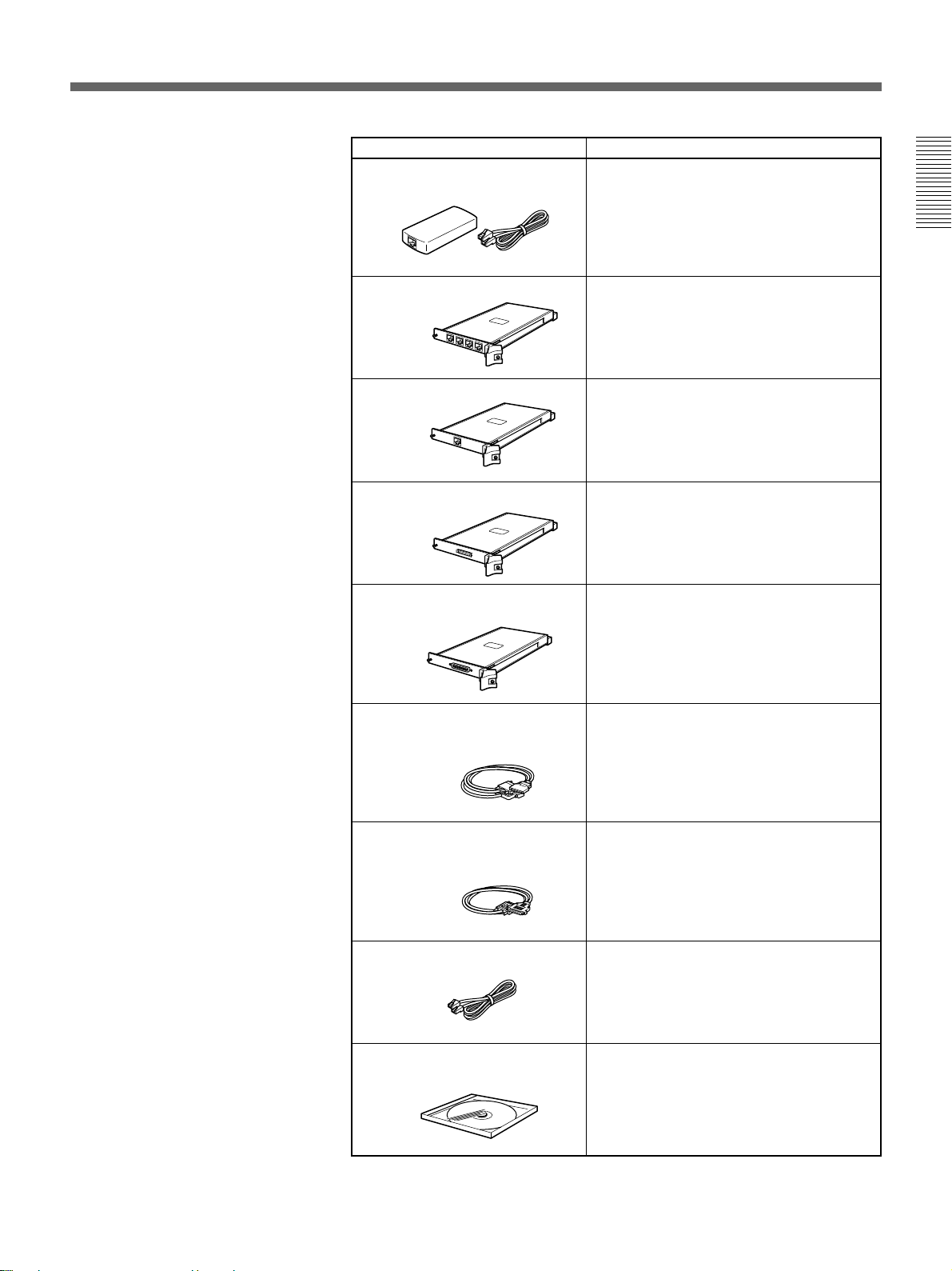
Basic System Equipment
The PCS-6000/6000P Multimedia Terminal forms the basis of the PCS6000 series system.
The PCS-6000/6000P Multimedia Terminal consists of the following
units:
Unit Description
PCS-P600/P600P
Multimedia Terminal Processor
PCS-C160/C160P
Camera Unit
Contains the video codec, audio codec,
echo canceler, network interfaces and
system controller.
This camera is equipped with the pan/tilt and
auto tracking functions.
Chapter 1
PCS-TM600
Desktop Terminal
PCS-A300
Microphone
PCS-R160
Remote Commander
Allows you to connect three microphones
and equips with three USB interface jacks
and single “Memory Stick” slot.
Used for two or three participants.
You can add two external PCS-A300
Microphones.
Controls the Multimedia Terminal.
This can also be used to operate a Sony TV
monitor.
Chapter 1 Preparation 11
Page 12

System Configuration
Options
Monitor
Chapter 1
A monitor is required for your meetings.
Unit Description
TV monitor
A TV is used as a meeting monitor and
speaker. It displays the remote party,
graphics, and menus.
If you use a Sony TV, you can operate it with
the Remote Commander supplied with the
Multimedia Terminal.
Two monitors are required for a dual-monitor
system.
Other options
RGB monitor or LCD projection
monitor
An RGB monitor or LCD projection monitor
can provide high-quality picture using the
XGA resolution.
The following optional devices are also available to improve your
meetings.
Unit Description
PCS-A300
Microphone
Allows you to accommodate extra two or
three participants.
You can add two microphones.
12 Chapter 1 Preparation
PCS-DS150/DS150P
Document Stand
Captures still objects and documents in color
for transmission to remote parties. Also, if
you connect a computer, you can use the
picture displayed on the computer in a
meeting.
To connect to the PCS-6000/6000P, use an
S-video cord (commercially available).
Page 13
Unit Description
PCS-E600
Extension Hub
Provides an extension cable and a hub for
the Desktop Terminal. These can extend the
cable for the Desktop Terminal up to 14 m
(46 feet).
Chapter 1
PCS-I600
BRI Board
PCS-I601
PRI Board
PCS-I602
V.35 Board
PCS-I603
RS-449 Board
PCS-K32
V.35 Conversion
Connector Cable
Provides four ISDN jacks. The connection
with 8B channels is available. Up to three
BRI Boards can be installed.
Provides single PRI jack. The connection via
the PRI interface is available.
Provides the V.35 connector. The
connection via the V.35 interface is
available.
Provides the RS-449 connector. The
connection via the RS-449 interface is
available.
Connects one end to the V.35 connector (on
the PCS-I602 V.35 Board) and the other end
to the terminal adaptor. (1 m, 3.3 ft)
PCS-K40
RS-449 Conversion
Connector Cable
PCS-K80
PRI Cable
PCS-UC601
Upgrade Kit
Connects one end to the RS-449 connector
(on the PCS-I603 RS-449 Board) and the
other end to the terminal adaptor. (1 m,
3.3 ft)
Connects one end to the PRI jack (on the
PCS-I601 PRI Board) and the other end to
the DSU.
Allows you to hold a meeting on the LAN
that corresponds to H.323.
You can connect up to six terminals in a
Multipoint Conference over a LAN.
Chapter 1 Preparation 13
Page 14

Basic System Connection
The figures on pages 15 and 16 show connection examples.
The examples are the cases when single optional PCS-I600 BRI Board is
installed and four ISDN lines are used.
Chapter 1
For details on installing the optional boards, see “Installing the Optional Board”
on page 109.
1 When using a TV monitor:
Connect a TV monitor using an optional video and audio cables.
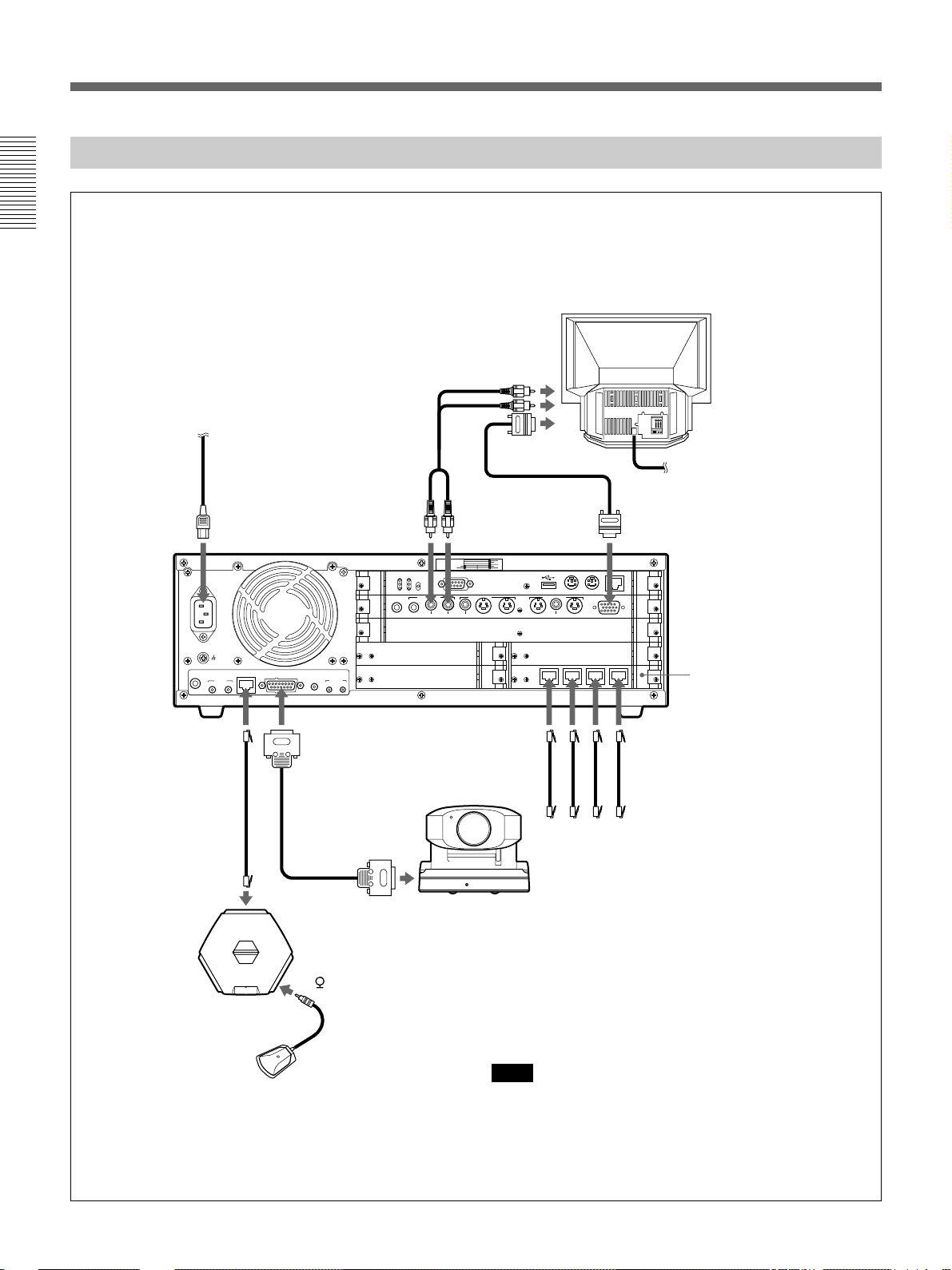
When using an RGB monitor or LCD projection monitor:
Connect an RGB monitor or LCD projection monitor using an optional
RGB and audio cables.
2 Connect the DESKTOP TERMINAL jack on the Multimedia Terminal
Processor and the PROCESSOR jack on the Desktop Terminal using
the supplied Desktop Terminal cable.
3 Connect the supplied microphone to the 1 jack on the Desktop
Terminal using the supplied Desktop Terminal cable.
4 Connect the CAMERA IN connector on the Multimedia Terminal
Processor and the PROCESSOR connector on the Camera Unit using
the supplied Camera Unit cable.
5 Connect the BRI A/B/C/D jacks on the BRI Board and an ISDN lines
using optional ISDN cables.
6 Connect the power cord to the AC IN connector and a wall outlet.
Note
Be sure to turn off all the equipment before making any connections.
14 Chapter 1 Preparation
Page 15
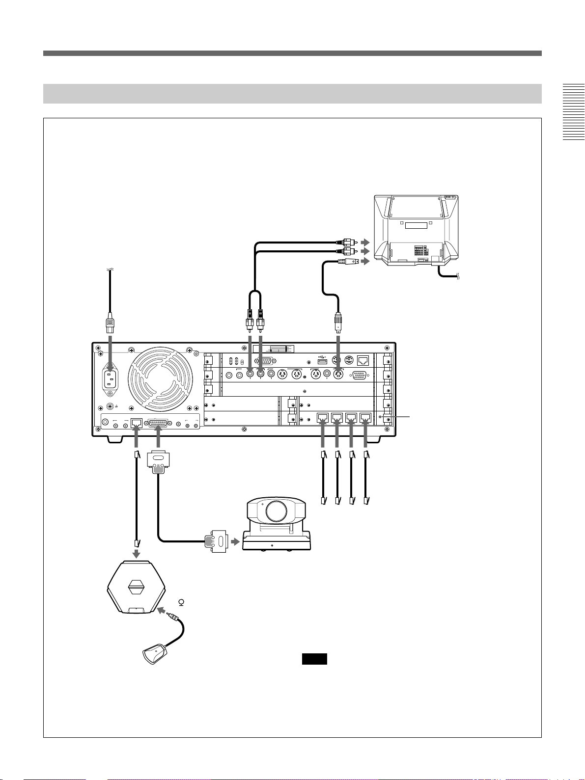
When Using a TV Monitor
Chapter 1
TV monitor
to audio input
to a wall outlet
Power cord
to AC IN
AC IN
~
AUDIO
LINE IN
to
DESKTOP
TERMINAL
Desktop Terminal
cable (supplied)
to PROCESSOR
Desktop
Terminal
Multimedia
Terminal Processor
DESKTOP
TERMINAL
MIC IN
12
CAMERA IN
Camera Unit
cable (supplied)
Audio cord
(not supplied)
to AUDIO
OUT MON L
CTRL S IR OUT
12
to CAMERA
IN
to PROCESSOR
RUNHD ERR
LNK100ACT
RST INT
AUDIO IN AUDIO OUT
AUX AUX MON L MON R
Camera Unit
to AUDIO
OUT MON R
SLOT
6
NUMBER
7
COM1
VIDEO IN VIDEO OUT
AUX2
AUX1 OBJECT MON2 MON1AUX
1
2
2
4
3
BRI
to S-video
input
S-video cord
(not supplied)
to VIDEO OUT
MON1
MOUSE
KEYBOARD
10/100BASE-T
RGB OUT
MONITOR
ABCD
to BRI A
to BRI B
to BRI C
to BRI D
to ISDN
Set the BACKUP
switch to ON.
to a wall outlet
Install the optional
PCS-I600 BRI Board.
ISDN modular cable (not supplied)
to 1
Microphone
Note
Do not connect to a network that applies an excess
voltage via the 10/100BASE-T and DESKTOP
TERMINAL connectors.
Chapter 1 Preparation 15
Page 16
Basic System Connection
When Using an RGB Monitor or LCD Projection Monitor
Chapter 1
RGB monitor or LCD
projection monitorr
to audio input
to a wall outlet
Power cord
to AC IN
AC IN
~
AUDIO
LINE IN
to
DESKTOP
TERMINAL
Desktop Terminal
cable (supplied)
to PROCESSOR
Desktop
Terminal
Multimedia
Terminal Processor
DESKTOP
TERMINAL
MIC IN
12
CAMERA IN
Camera Unit
cable (supplied)
Audio cord
(not supplied)
to AUDIO
OUT MON L
CTRL S IR OUT
12
to CAMERA
IN
to PROCESSOR
RUNHD ERR
LNK100ACT
RST INT
AUDIO IN AUDIO OUT
AUX AUX MON L MON R
Camera Unit
to AUDIO
OUT MON R
SLOT
6
NUMBER
7
COM1
VIDEO IN VIDEO OUT
AUX2
AUX1 OBJECT MON2 MON1AUX
to RGB input
1
2
2
4
3
BRI
ABCD
to BRI A
Set the BACKUP
switch to ON.
MOUSE
KEYBOARD
to BRI B
to BRI C
to ISDN
to a wall outlet
RGB cable (not supplied)
to RGB OUT MONITOR
10/100BASE-T
RGB OUT
MONITOR
Install the optional
PCS-I600 BRI Board.
ISDN modular cable (not supplied)
to BRI D
16 Chapter 1 Preparation
to 1
Microphone
Note
Do not connect to a network that applies an excess
voltage via the 10/100BASE-T and DESKTOP
TERMINAL connectors.
Page 17
Preparing the System
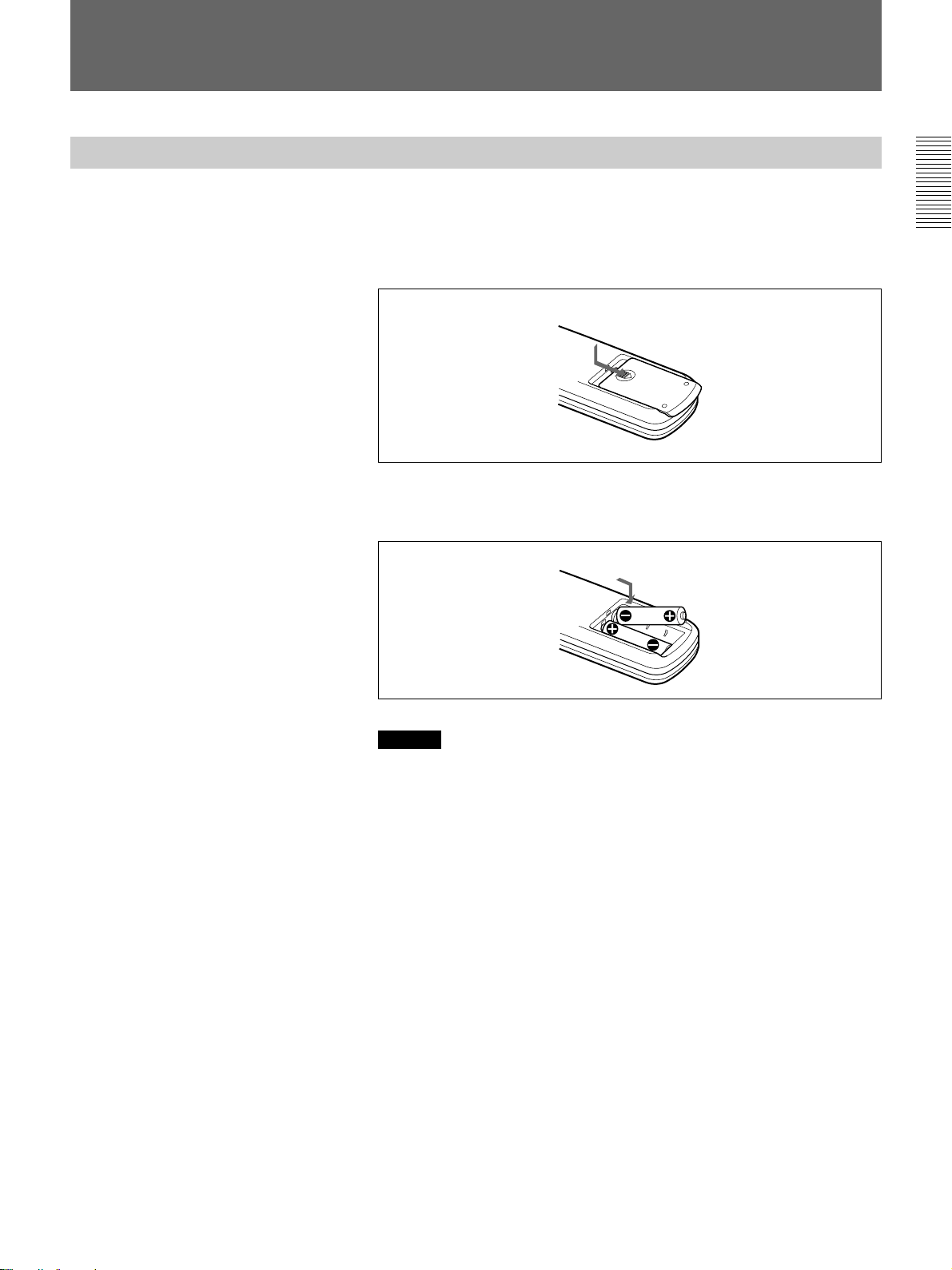
Inserting Batteries into the Remote Commander
The supplied Remote Commander controls most of the functions. This
section describes how to insert batteries into the Remote Commander.
1 Remove the battery compartment cover.
2 Insert two size AA (R6) batteries (supplied) with correct 3 and #
polarity into the battery compartment.
Chapter 1
When inserting the
batteries, be sure to put
the negative end at first.
Caution
Be sure to place the negative # end of the battery at first. If you place
the positive 3 end at first, there is a possibility of damaging the
insulated film covering the battery and creating a short circuit.
3 Replace the cover.
Battery life
When the Remote Commander no longer functions properly, replace both
the batteries.
Notes on batteries
To avoid possible damage from battery leakage or corrosion, observe the
following:
•Be sure to insert the batteries in the correct direction.
•Do not mix old and new batteries, or different types of batteries.
•Do not attempt to charge dry-cell batteries.
•If you do not intend to use the Remote Commander for a long time,
remove the batteries.
If battery leakage occurs, clean the battery compartment and replace all
the batteries.
Chapter 1 Preparation 17
Page 18
Preparing the System
Preparing a Monitor
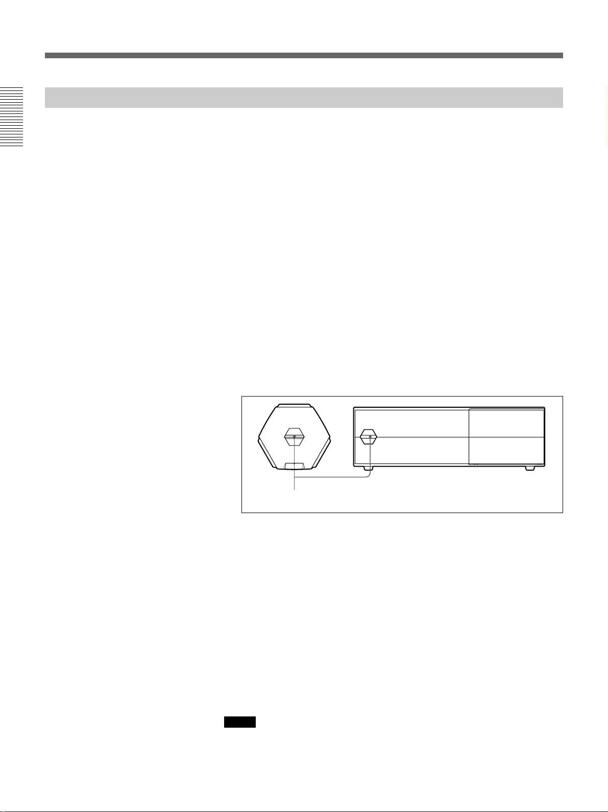
To install the IR repeater
Chapter 1
Note
The IR repeater cannot be used with an RGB monitor, an LCD projection
monitor, or monitors other than Sony products.
Insert the IR repeater below the remote sensor of the TV monitor. Once
you set the IR repeater, you can turn on the Multimedia Terminal and a
Sony TV monitor together by pressing the I/1 button on the Remote
Commander or Desktop Terminal.
If the IR repeater does not function properly, set Monitor Mode in the
General Setup menu to MODE2 (PCS-6000); to MODE4 (PCS-6000P).
For details on the Monitor Mode setting, see “General Setup Menu” on page 39.
AC IN
~
DESKTOP
AUDIO
TERMINAL
LINE IN
12
MIC IN
to IR OUT1
CAMERA IN
CTRL S IR OUT
12
Remote sensor
IR repeater (supplied)
When using a Sony TV monitor
The TV monitor can be operated from the Remote Commander.
For details on operating the Remote Commander, see “To operate a Sony TV
monitor” on page 123.
To adjust the TV monitor screen
Use the controls on the TV monitor to adjust the screen (picture, hue,
contrast, brightness, and sharpness).
For details on adjusting the screen, refer to the operating instructions supplied
with the TV monitor.
18 Chapter 1 Preparation
Note
Do not activate the surround function of the TV monitor. This causes
strange sounds since the echo canceler on the Multimedia Terminal will
not function properly.
Page 19

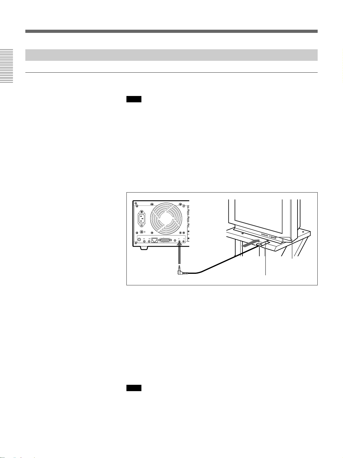
Setting the Initial Volume Level on the Monitor
When you adjust the volume, use the VOLUME/DOC-BRIGHT +/–
buttons on the Remote Commander.
1 Set the volume level to the middle position by pressing the VOLUME/
DOC-BRIGHT +/– buttons on the Remote Commander.
2 Adjust the volume with the monitor’s control.
Set it to the proper level for listening to a remote party.
Chapter 1
Chapter 1 Preparation 19
Page 20

Chapter 1
Turning the System On/Off
This section describes how to turn on and off the Multimedia Terminal.
Note
Set the CONF/DOC/TV selector on the Remote Commander to “CONF”
when operating the Multimedia Terminal.
Turning On
The following describes how to turn on the Multimedia Terminal.
1 When using a TV monitor:
Make sure the TV monitor is on standby.
For details on how to set the TV monitor into a standby state, refer to the
operating instructions supplied with the TV monitor.
When using an RGB monitor or LCD projection monitor:
Turn on the RGB monitor or LCD projection monitor.
2 Turn on the power of any other equipment to be used during the
meeting.
3 Press the I/1 switch on the Multimedia Terminal Processor.
Soon, the Multimedia Terminal Processor, Camera Unit, Desktop
Terminal, and the TV monitor are turned on.
The power lamps (green) on the Multimedia Terminal Processor and
Desktop Terminal light up, and the POWER lamp (green) on the
Camera Unit lights up. The picture shot by the local camera appears on
the monitor screen after the preparation is completed.
Power lamp
20 Chapter 1 Preparation
POWER lampI/1 switch/power lamp
Note
After the power is turned on, the camera performs training movements. Be
careful not to catch your finger.
Page 21
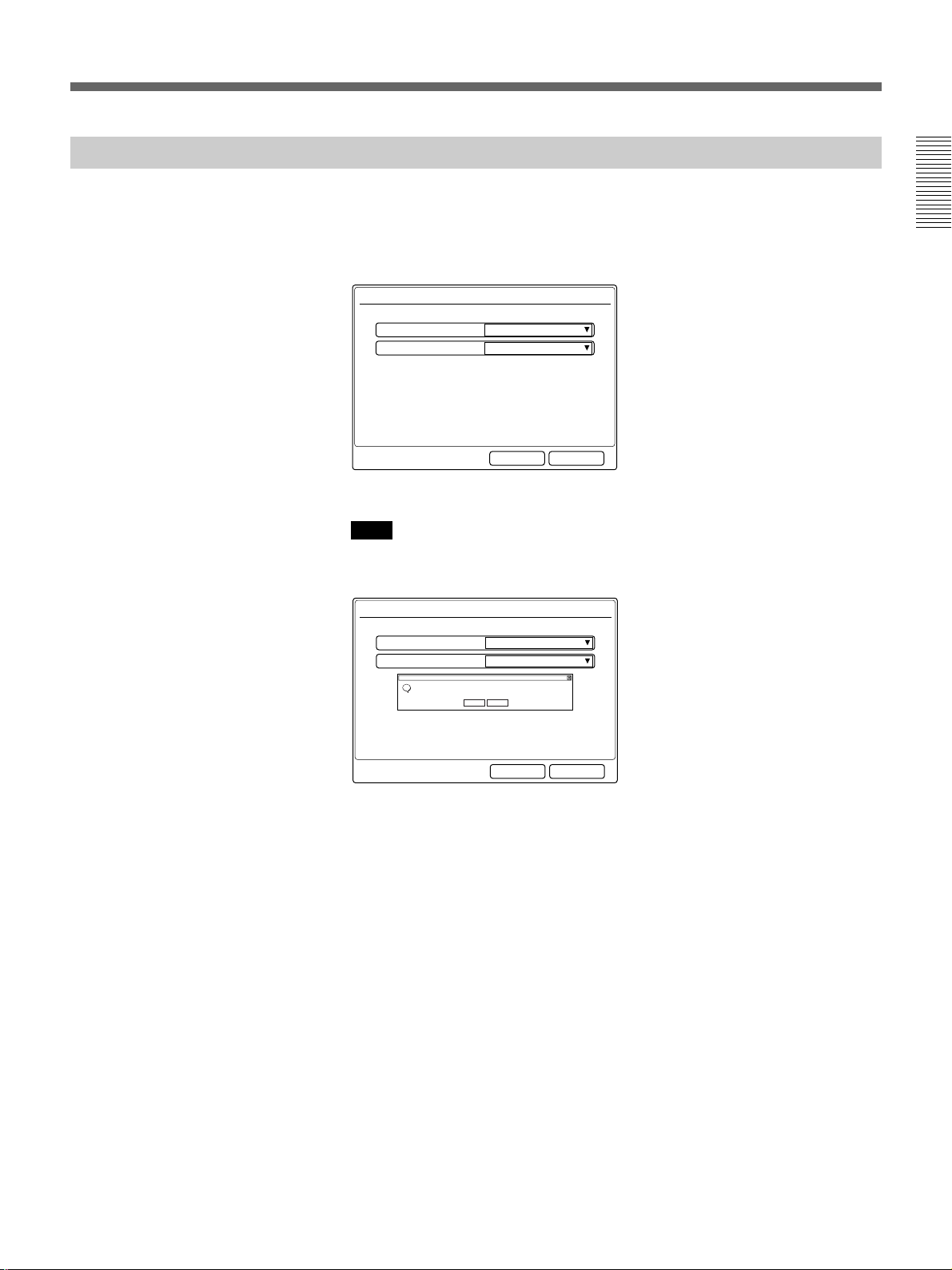
When the Multimedia Terminal is turned on for the first time
The setup wizard appears on the monitor screen after the self-diagnostic is
completed.
Register your local system data following the wizard.
It takes about 5 minutes for the setup wizard to appear on the screen.
General Setup Wizard
Chapter 1
Language:
English
1024x768VGA/XGA:
CancelNext
Register following the instructions provided on the wizard’s screens.
Note
In the setup wizard, there is a window that asks if you want to restart your
computer.
General Setup Wizard
Language:
System Settings Change
Windows 2000 has finished installing new devices. You must restart your computer before the new settings will take effect.
?
Do you want to restart your computer now?
English
1024x768VGA/XGA:
Yes No
CancelNext
When this window is displayed, move the cursor to Yes with the joystick,
then press it down.
Your computer restarts, and the setup wizard re-appears.
1 Select the language of the messages with the joystick on the Remote
Commander, then press the joystick.
English: Displays messages in English.
French: Displays messages in French.
German: Displays messages in German.
Japanese: Displays messages in Japanese.
Spanish: Displays messages in Spanish.
Italian: Displays messages in Italian.
Chinese: Displays messages in Chinese.
2 Select the resolution of the monitor with the joystick on the Remote
Commander, then press the joystick.
640×480: Sets the resolution to 640×480.
1024×768: Sets the resolution to 1024×768.
Chapter 1 Preparation 21
(Continued)
Page 22
Turning the System On/Off
3 Select Next with the joystick on the Remote Commander, then press
the joystick.
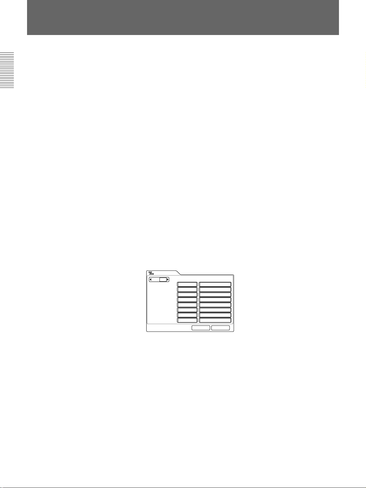
The ISDN Setup menu (Page 1) appears on the monitor screen.
Chapter 1
ISDN Setup Wizard
Country/Region:
USA
1Country/Region Code:
National ISDNProtocol:
CancelNextPrevious
4 Select your country/region with the joystick, then press the joystick.
5 Enter your country/region code in the Country/Region Code box.
(e.g., enter “1” for the USA.)
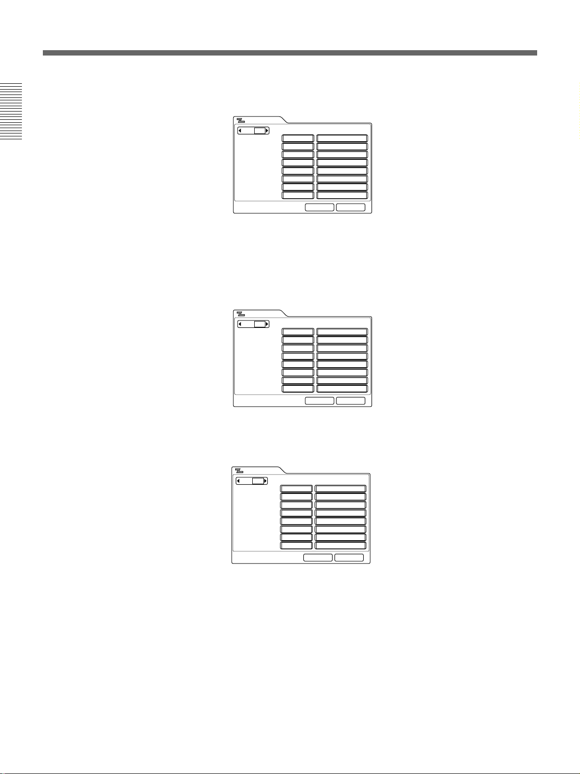
6 Select Next with the joystick on the Remote Commander, then press
the joystick.
The ISDN Setup menu (Page 2) appears on the monitor screen.
ISDN Setup Wizard
A1:
A2:
B1:
B2:
C1:
C2:
D1:
D2:
Slot5 BRI
Area Code Local Number
CancelNextPrevious
22 Chapter 1 Preparation
7 Enter your area code in the Area Code boxes A1 to D2.
Do not enter the first zero number of your area code.
(e.g., enter only “408” for California.)
8 Enter your telephone number and sub-address (if you set your sub-
address) in the Local Number boxes A1 to D2.
Enter the asterisk (
address. You cannot use the alphabet in a sub-address.
Note
Register information to the next page or downward if you have
installed two or three optional PCS-I600 BRI Boards or one PCS-I601
PRI Board and using five ISDN lines or more.
) after the telephone number, then enter the sub-
Page 23

9 Select Next with the joystick on the Remote Commander, then press
the joystick.
The ISDN Setup (SPID) menu appears on the monitor screen. (This is
only for the USA and Canada.)
10Set up the ISDN Setup (SPID) menu. (This is only for the USA.)
For details on the SPID registration, see “SPID Registration for Customers in
the USA” on page 25.
11Select Next with the joystick on the Remote Commander, then press
the joystick.
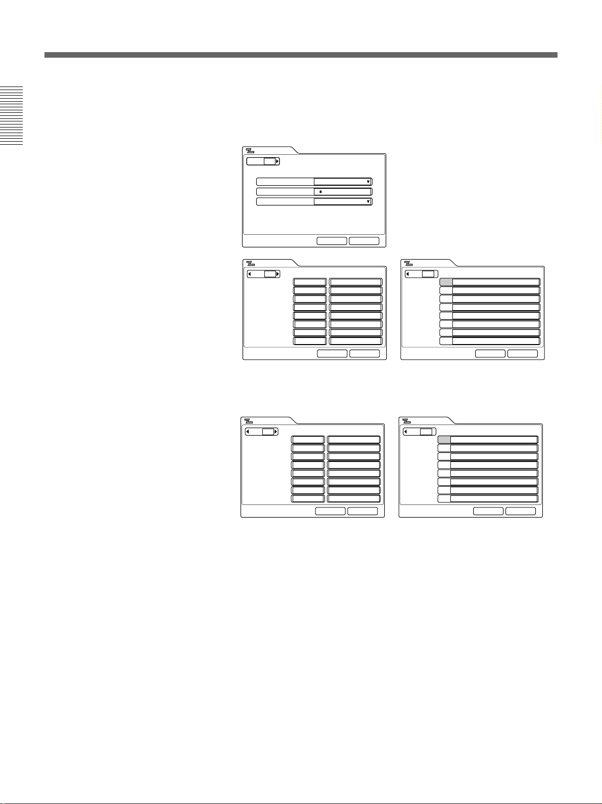
The LAN Setup menu appears on the monitor screen.
LAN Setup Wizard
Chapter 1
DHCP Mode:
IP Address:
Network Mask:
Gateway Address:
DNS Address:
Auto
PCSXXXXXXHost Name:
____.____.____.____
____.____.____.____
____.____.____.____
____.____.____.____
CancelNextPrevious
12Set up the LAN Setup menu.
For details on the LAN Setup menu, see “LAN Setup Menu” on page 43.
13Select Next with the joystick on the Remote Commander, then press
the joystick.
The message for verification appears.
14Select Save with the joystick on the Remote Commander, then press
the joystick.
The setting is saved. Also, set up other menus (pages 32 to 46).
To cancel the setup
Select Cancel with the joystick on the Remote Commander, then press the
joystick. Or press the RETURN button on the Remote Commander.
To page up or down the menu
To page up, select Previous with the joystick on the Remote Commander,
then press the joystick. To page down, select Next with the joystick, then
press the joystick.
Chapter 1 Preparation 23
Page 24
Turning the System On/Off
Setting the System (Multimedia Terminal) to be on Standby
Chapter 1
The Multimedia Terminal is turned into standby mode to save power if
you do not operate the Multimedia Terminal for about 1 to 99 minutes.
The standby lamps on the Multimedia Terminal Processor and Desktop
Terminal flash while in standby mode.
Once a call comes in, the standby mode is automatically released.
When the system is on standby, you can turn the system on with the I/1
button on the Remote Commander.
1 Press the I/1 button on the Remote Commander or Desktop Terminal.
The indication “Power off?” appears on the monitor screen.
2 Select OK with the joystick on the Remote Commander, then press the
joystick, or press the I/1 button on the Remote Commander or
Desktop Terminal.
The Multimedia Terminal Processor, Desktop Terminal, Camera Unit,
and the TV monitor are turned into standby.
The standby lamps (orange) on the Multimedia Terminal Processor and
Desktop Terminal light up.
Standby lamp
To cancel turning into standby
Select Cancel using the joystick on the Remote Commander in step 2, then
press the joystick.
To release the standby mode
Press any of the buttons on the Remote Commander.
To set the time that the unit turns into standby mode
Set the time by setting Standby Time in the General Setup menu. If you do
not want to use the standby function, set Standby Mode to Off.
24 Chapter 1 Preparation
For details on the Standby Time and Standby Mode settings, see “General Setup
Menu” on page 39.
Notes
•The POWER lamp on the Camera Unit does not flash even if the system
is in standby mode.
•A Sony TV monitor is turned into standby mode.
Page 25

Turning Off
The following describes how to turn off the Multimedia Terminal.
1 Press and hold the I/1 switch on the Multimedia Terminal Processor
for two seconds. The power lamp will blink for about one minute, then
the power shuts off.
2 Turn off the power of any other equipment to be used during the
meeting.
Notes
•If you are not going to use the system for an extended period, set the I/1
switch to off.
•You cannot receive any calls from remote parties if the I/1 switch is set
to off.
Chapter 1
Chapter 1 Preparation 25
Page 26
Chapter 1
SPID Registration for Customers in the USA
If the system is connected to a network switch of the following types, you
can use ISDN lines.
•Network switch type: AT&T 5ESS
Network switch software version: 5E8 or later (for National ISDN-1
and National ISDN-2)
•Network switch type: Northern Telecom (NTI) DMS-100
Network switch software version: BCS34 or later (for National ISDN-1
and National ISDN-2)
•Network switch type: AT&T 5ESS
Network switch software version: 5E8 or later (for Multipoint or Pointto-Point Custom ISDN)
•Network switch type: Northern Telecom (NTI) DMS-100
Network switch software version: BCS34 or later (for Custom ISDN)
In these cases, you shall register the LDN (Local Directory Number:
seven-digit local phone number).
Follow the steps below to register the LDN(s).
1 Open the ISDN Setup menu.
2 Select USA in the Country/Region box. Select the suitable Protocol in
the Protocol box.
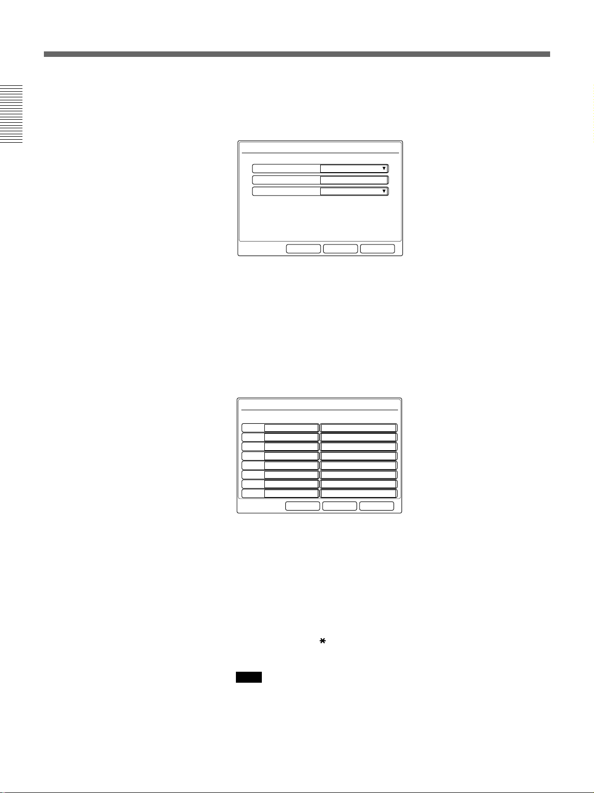
3 Open the ISDN Setup menu (Page 2).
ISDN Setup
Page: 2/3
Area Code
A1:
A2:
B1:
B2:
C1:
C2:
D1:
D2:
Local Number
CancelSave
4 Enter your LDN (s) and sub-address in the Local Number boxes.
If one ISDN line is used, register the LDN in the boxes A1 and A2.
If two ISDN lines are used, register the LDNs in the boxes A1, A2, B1,
B2.
If three ISDN lines are used, register the LDNs in the boxes A1, A2,
B1, B2, C1, C2.
If four ISDN lines are used, register the LDNs in the boxes A1, A2,
B1, B2, C1, C2, D1, D2.
26 Chapter 1 Preparation
Page 27

If the network switch type is AT&T 5ESS (National ISDN)
Each LDN is given for four channels (CH A1 and A2, CH B1 and B2,
CH C1 and C2, CH D1 and D2)
or
Each LDN is different as a separate LDN is given for each channel.
The following shows the use of three ISDN lines for AT&T 5ESS
(National ISDN).
In case of each LDN is given for two channels.
ISDN Setup
Page: 2/3
A1:
Area Code
408
408A2:
408B1:
408B2:
408C1:
408C2:
408D1:
408D2:
Local Number
9876532
9876532
9871356
9871356
9852464
9852464
9853141
9853141
CancelSave
In case of each LDN is different as a separate LDN is given for each
channel.
ISDN Setup
Page: 2/3
A1:
Area Code
408
408A2:
408B1:
408B2:
408C1:
408C2:
408D1:
408D2:
Local Number
9876543
9876544
9871234
9871235
9852468
9852469
9853245
9853246
CancelSave
Chapter 1
If the network switch type is AT&T 5ESS (Multipoint or Point-toPoint Custom ISDN)
Each LDN is given for four channels (CH A1 and A2, CH B1 and B2,
CH C1 and C2, CH D1 and D2).
The following shows the use of four ISDN lines for AT&T 5ESS
(Multipoint Custom ISDN).
ISDN Setup
Page: 2/3
A1:
Area Code
408
408A2:
408B1:
408B2:
408C1:
408C2:
408D1:
408D2:
Local Number
9876532
9876532
9871356
9871356
9852464
9852464
9853141
9853141
CancelSave
(Continued)
Chapter 1 Preparation 27
Page 28
SPID Registration for Customers in the USA
The following shows the use of four ISDN lines for AT&T 5ESS
(Point-to-Point Custom ISDN).
ISDN Setup
Page: 2/3
Chapter 1
If the network switch type is NTI DMS-100 (National ISDN or
Custom ISDN)
Each LDN is different as a separate LDN is given for each channel.
The following shows the use of four ISDN lines for NTI DMS-100
(National ISDN).
ISDN Setup
Page: 2/3
A1:
A1:
Area Code
408
408A2:
408B1:
408B2:
408C1:
408C2:
408D1:
408D2:
Area Code
408
408A2:
408B1:
408B2:
408C1:
408C2:
408D1:
408D2:
Local Number
9876532
9876532
9871356
9871356
9852464
9852464
9853141
9853141
CancelSave
Local Number
9876543
9876544
9871234
9871235
9852468
9852469
9853245
9853246
CancelSave
The following shows the use of four ISDN lines for NTI DMS-100
(Custom ISDN).
ISDN Setup
Page: 2/3
A1:
Area Code
408
408A2:
408B1:
408B2:
408C1:
408C2:
408D1:
408D2:
Local Number
9876543
9876544
9871234
9871235
9852468
9852469
9853245
9853246
CancelSave
5 Open the ISDN Setup (SPID) menu.
SPID in the ISDN Setup (SPID) menu and the Local Number in the
ISDN Setup menu are entered in pairs and should not be crossed with
BRI channels as each has its own LDN.
Be sure to enter each number in pairs. If it is crossed, you must correct
the SPID-LDN pairs.
28 Chapter 1 Preparation
Page 29

If the network switch type is AT&T 5ESS (National ISDN)
The following shows the use of four ISDN lines.
In case of each LDN is given for two channels.
ISDN Setup
Page: 2/3
A1:
Area Code
408
408A2:
408B1:
408B2:
408C1:
408C2:
408D1:
408D2:
Local Number
9876532
9876532
9871356
9871356
9852464
9852464
9853141
9853141
CancelSave
ISDN Setup
Page: 3/3
SPID
019876532001
A1:
A2:
019871356001B1:
B2:
019852464001C1:
C2:
019853141001D1:
D2:
CancelSave
In case of each LDN is different as a separate LDN is given for each
channel.
ISDN Setup
Page: 2/3
A1:
Area Code
408
408A2:
408B1:
408B2:
408C1:
408C2:
408D1:
408D2:
Local Number
9876543
9876544
9871234
9871235
9852468
9852469
9853245
9853246
CancelSave
ISDN Setup
Page: 3/3
SPID
019876543001
A1:
019876544001A2:
019871234001B1:
019871235001B2:
019852468001C1:
019852469001C2:
019853245001D1:
019853246001D2:
CancelSave
Chapter 1
If the network switch type is AT&T 5ESS (Multipoint Custom ISDN)
The following shows the use of four ISDN lines.
ISDN Setup
Page: 1/3
USACountry/Region:
1 10Country/Region Code:
AT&T P-MPProtocol:
CancelSave
ISDN Setup
Page: 2/3
A1:
Area Code
408
408A2:
408B1:
408B2:
408C1:
408C2:
408D1:
408D2:
Local Number
9876532
9876532
9871356
9871356
9852464
9852464
9853141
9853141
CancelSave
ISDN Setup
Page: 3/3
SPID
019876532001
A1:
A2:
019871356001B1:
B2:
019852464001C1:
C2:
019853141001D1:
D2:
CancelSave
(Continued)
Chapter 1 Preparation 29
Page 30
SPID Registration for Customers in the USA
If the network switch type is AT&T 5ESS (Point-to-Point Custom
ISDN)
You do not have to enter SPID.
The following shows the use of four ISDN lines.
Chapter 1
ISDN Setup
Page: 1/3
USACountry/Region:
1 12Country/Region Code:
AT&T P-PProtocol:
CancelSave
ISDN Setup
Page: 2/3
A1:
Area Code
408
408A2:
408B1:
408B2:
408C1:
408C2:
408D1:
408D2:
Local Number
9876532
9876532
9871356
9871356
9852464
9852464
9853141
9853141
CancelSave
ISDN Setup
Page: 3/3
SPID
A1:
A2:
B1:
B2:
C1:
C2:
D1:
D2:
If the network switch type is NTI DMS-100 (National ISDN)
The following shows the use of four ISDN lines.
ISDN Setup
Page: 2/3
A1:
Area Code
408
408A2:
408B1:
408B2:
408C1:
408C2:
408D1:
408D2:
Local Number
9876543
9876544
9871234
9871235
9852468
9852469
9853245
9853246
CancelSave
ISDN Setup
Page: 3/3
SPID
A1:
019876543001
019876544001A2:
019871234001B1:
019871235001B2:
019852468001C1:
019852469001C2:
019853245001D1:
019853246001D2:
CancelSave
CancelSave
30 Chapter 1 Preparation
Page 31

If the network switch type is NTI DMS-100 (Custom ISDN)
The following shows the use of four ISDN lines.
ISDN Setup
Page: 1/3
USACountry/Region:
1 11Country/Region Code:
Northern TelecomProtocol:
CancelSave
Chapter 1
ISDN Setup
Page: 2/3
A1:
Area Code
408
408A2:
408B1:
408B2:
408C1:
408C2:
408D1:
408D2:
Local Number
9876543
9876544
9871234
9871235
9852468
9852469
9853245
9853246
CancelSave
ISDN Setup
Page: 3/3
A1:
SPID
019876543001
019876544001A2:
019871234001B1:
019871235001B2:
019852468001C1:
019852469001C2:
019853245001D1:
019853246001D2:
CancelSave
You should let the remote party user know the contents of your LDN.
The remote party dial list and the LDN should be kept in pairs.
The following shows a setup using four ISDN lines.
ISDN Setup
Page: 2/3
A1:
Area Code
408
408A2:
408B1:
408B2:
408C1:
408C2:
408D1:
408D2:
Local Number
9876543
9876544
9871234
9871235
9852468
9852469
9853245
9853246
CancelSave
ISDN Setup
Page: 3/3
A1:
SPID
913219876543
913219876544A2:
913219871234B1:
913219871235B2:
913219852468C1:
913219852469C2:
913219853245D1:
913219853246D2:
CancelSave
6 Select Save with the joystick on the Remote Commander, then press
the joystick.
7 Select OK with the joystick on the Remote Commander, then press the
joystick.
The registration is complete.
Chapter 1 Preparation 31
Page 32

Chapter 1
Menu Items in the Setup Menu
Dial Setup Menu
Sets up the attribute for calling.
Page 1
Dial Setup
Page: 1/4
BRILine I/F:
AutoBonding:
8BNumber of Lines:
1920 KbpsLAN Bandwidth:
Prefix-NonePrefix:
AutoRestrict:
Line I/F: Selects the line interface.
BRI: Connects to a TV conferencing system via the BRI interface.
PRI: Connects to a TV conferencing system via the PRI interface.
PRI-S: Connects to a TV conferencing system using H
America), H
Telephone: Connects to a phone to have a voice meeting via the normal
ISDN line.
V.35: Connects to a TV conferencing system via the V.35 interface.
LAN: Connects to a TV conferencing system using a LAN.
RS-449: Connects to a TV conferencing system via the RS-449 interface.
12 (for European countries) of the PRI interface.
CancelSave
0, H11 (for North
Notes
•When the optional BRI Board is not installed, you cannot select BRI from
Line I/F.
•When the optional PRI Board is not installed, you cannot select PRI from
Line I/F.
•When the optional V.35 Board is not installed, you cannot select V.35
from Line I/F.
•When the optional RS-449 Board is not installed, you cannot select RS449 from Line I/F.
•When the system is not upgraded using the optional PCS-UC601
Upgrade Kit, you cannot select LAN from Line I/F.
Bonding: Selects whether to use the Inverse Multiplexer interface or not.
Auto: Normally, select this setting.
On: Connects to a remote party via the Inverse Multiplexer interface.
Number of Lines: Selects the number of lines usable for BONDING
calling. This item can be set between 1B and 30B.
32 Chapter 1 Preparation
Page 33

LAN Bandwidth: Sets up the bandwidth when using a LAN or the PRI-S
interface. This time can be set to 384K or 1536K (for North America) /
1920K (for European countries) when using the PRI-S interface. When you
are using a LAN, you can choose from among the following bandwidths.
64 Kbps, 128 Kbps, 384 Kbps, 512 Kbps, 768 Kbps, 1024 Kbps, 1280
Kbps, 1536 Kbps, 1792 Kbps, 1920 Kbps, and Other.
When Other is selected, enter a numerical value. You can enter a
bandwidth of from 1 Kbps to 1920 Kpbs.
When setting Line I/F to PRI-S, LAN Bandwidth changes to PRI-S
Bandwidth.
Prefix: Selects the prefix number setting from the following.
Prefix-None: Does not use the prefix number.
Prefix-A: Uses the setting A set in the Dial Setup menu.
Prefix-B: Uses the setting B set in the Dial Setup menu.
Prefix-C: Uses the setting C set in the Dial Setup menu.
For details on setting the prefix, see page 34.
Restrict: Selects the transfer rate via the ISDN line.
Auto: Normally, select this setting.
56K: Selects this setting when you call a region or country via the 56
Kbps transfer rate.
Chapter 1
Page 2
Dial Setup
Page: 2/4
H.263Video Mode:
15fpsVideo Frame:
AutoAudio Mode:
up to 128K:G.728Audio Mode Threshold:
OnFar End Camera Control:
OffT.120 Data:
CancelSave
Video Mode: Selects the protocol for the video encoding.
H.261: Sends pictures based on Recommendation H.261 (When sending
pictures using Annex D).
H.263: Sends pictures based on Recommendation H.263.
Video Frame: Selects the number of frames.
15fps: Sends pictures at a maximum rate of 15 frames per second.
30fps: Sends pictures at a maximum rate of 30 frames per second.
Audio Mode: Selects the protocol for the audio encoding.
Auto: Automatically selects the audio encoding according to the number
of used lines.
G.728: The audio bandwidth is narrow but the picture quality is better.
(3.4 kHz)
G.722: The audio bandwidth is wider for better sound quality. (7 kHz)
G.723.1: The video bandwidth is wider for better picture quality. (Only
when Line I/F is set to LAN)
Chapter 1 Preparation 33
Page 34

Menu Items in the Setup Menu
Chapter 1
Audio Mode Threshold: Selects the setup of the Auto setting of Audio
Mode.
up to 64K:G.728: Sets the Auto setting of Audio Mode to G.728 when
the used-line is 1B channel and sets to G.722 when it is 2B channels
or more.
up to 128K:G.728: Sets the Auto setting of Audio Mode to G.728 when
the used-line is 2B channels or less and sets to G.722 when it is 3B
channels or more.
up to 192K:G.728: Sets the Auto setting of Audio Mode to G.728 when
the used-line is 3B channels or less and sets to G.722 when it is 4B
channels or more.
Far End Camera Control: Selects whether to control the far end
camera or not.
On: Operates the far end camera.
Off: Does not operate the far end camera.
T.120 Data: Selects whether to have a T.120 data meeting.
On: Holds a T.120 data meeting.
Off: Does not hold a T.120 data meeting.
Page 3
Enter “9” when you have to dial nine to reach an outside line.
Dial Setup
Page: 3/4
Prefix-A:
Prefix-B:
Prefix-C:
CancelSave
Prefix-A: Sets up a prefix number that will be registered for Prefix-A in
the Dial Setup menu.
Prefix-B: Sets up a prefix number that will be registered for Prefix-B in
the Dial Setup menu.
Prefix-C: Sets up a prefix number that will be registered for Prefix-C in
the Dial Setup menu.
Notes
•The number input in these boxes above is automatically dialed before the
telephone number is dialed.
•Prefix numbers that can be entered consist of 0 to 9,
, , and –.
34 Chapter 1 Preparation
Page 35

Page 4
Dial Setup
Page: 4/4
AutoTelephone Mode:
OffMore Options Enable:
OnV.35 RS-366:
OnPCS-5000 Series Mode:
CancelSave
Telephone Mode: Selects the audio protocol for the voice meeting.
Auto: Selects the protocol automatically.
G.711 µ-law: Selects the µ-law protocol.
G.711 A-law: Selects the A-law protocol.
More Options Enable: Selects whether to enable the dial attribute set in
the Dial Setup menu for each dial list.
On: Enables the dial attribute for each dial list.
Off: Disables the dial attribute for each dial list.
Notes
•Settings made for the Dial List from the More Options menu have
priority over those made from the Dial Setup menu.
•You cannot make settings for Audio Mode Threshold, Prefix, More
Option Enable, V.35 RS-366, or 5000 Series Mode on the More Options
menu of the Dial List.
Chapter 1
V.35 RS-366: Selects whether to specify the telephone number when
connecting via the V.35 interface.
On: When specifying the telephone number.
Off: When not specifying the telephone number.
Note
If an optional V.35 board has not been installed, you cannot select V.35
RS-366.
PCS-5000 Series Mode: Selects whether or not to use the drawing tools
or the pointer when connecting with the PCS-5000/5000P/5100/5100P.
On: When using the pointer or the drawing function.
Off: When not using the pointer or the drawing function.
Note
Set to Off when connecting with other terminals than the PCS-5000/
5000P/5100/5100P. When it is set to On, you cannot use some of the
functions, such as the remote camera control function.
Chapter 1 Preparation 35
Page 36

Menu Items in the Setup Menu
Answer Setup Menu
Chapter 1
Page 1
Sets up the communication items for receiving.
Answer Setup
Page: 1/2
OnAuto Answer:
8BNumber of Lines:
AutoRestrict:
1920 KbpsLAN Bandwidth:
OffISDN MSN:
OnPCS-5000 Series Mode:
CancelSave
Auto Answer: Selects the answer mode.
On: Answers calls in auto answer mode.
Off: Answers calls in manual answer mode.
Number of Lines: Selects the number of lines usable for receiving. This
item can be set between 1B and 30B.
Restrict: Selects the transfer rate via the ISDN line.
Auto: Normally, select this setting.
56K: Selects this setting when you call a region or country via the 56
Kbps transfer rate.
LAN Bandwidth: Selects the bandwidth to be used when communicating
over a LAN. If you select Other, you can enter a value from 1 Kbps to
1920 Kbps.
ISDN MSN: Selects whether you are using the Multiple Subscriber
Number.
On: When you are using the Multiple Subscriber Number.
Off: When you are not using the Multiple Subscriber Number.
PCS-5000 Series Mode: Selects whether or not to use the drawing tools
or the pointer when connecting with the PCS-5000/5000P/5100/5100P.
On: When using the pointer or the drawing function.
Off: When not using the pointer or the drawing function.
36 Chapter 1 Preparation
Note
Set to Off when connecting with other terminals than the PCS-5000/
5000P/5100/5100P. When it is set to On, you cannot use some of the
functions, such as the remote camera control function.
Page 37

Page 2
Answer Setup
Page: 2/2
H.261Video Mode:
30fpsVideo Frame:
AutoAudio Mode:
up to 128K:G.728Audio Mode Threshold:
OnFar End Camera Control:
OffT.120 Data:
CancelSave
Video Mode: Selects the protocol for the video encoding.
H.261: Receives pictures based on Recommendation H.261.
H.263: Receives pictures based on Recommendation H.263.
Video Frame: Selects the number of frames.
15fps: Receives pictures at a maximum rate of 15 frames per second.
30fps: Receives pictures at a maximum rate of 30 frames per second.
Audio Mode: Selects the protocol for the audio encoding.
Auto: Automatically selects the audio encoding according to the number
of used lines.
G.728: The audio bandwidth is narrow but the picture quality is better.
(3.4 kHz)
G.722: The audio bandwidth is wider for better sound quality. (7 kHz)
Audio Mode Threshold: Selects the setup of the Auto setting of Audio
Mode.
up to 64K:G.728: Sets the Auto setting of Audio Mode to G.728 when
the used-line is 1B channel and sets to G.722 when it is 2B channels
or more.
up to 128K:G.728: Sets the Auto setting of Audio Mode to G.728 when
the used-line is 2B channels or less and sets to G.722 when it is 3B
channels or more.
up to 192K:G.728: Sets the Auto setting of Audio Mode to G.728 when
the used-line is 3B channels or less and sets to G.722 when it is 4B
channels or more.
Far End Camera Control: Selects whether the near end camera is
controled or not.
On: Operates the near end camera.
Off: Does not operate the near end camera.
T.120 Data: Selects whether to have a T.120 data meeting.
On: Holds a T.120 data meeting.
Off: Does not hold a T.120 data meeting.
Chapter 1
Chapter 1 Preparation 37
Page 38

Menu Items in the Setup Menu
Multipoint Setup Menu
Make the settings for a teleconference with multiple locations.
Chapter 1
Multipoint Setup
Page: 1/2
OffMultipoint Mode:
SplitBroadcast Mode:
CancelSave
Multipoint Setup
Page: 2/2
2BNumber of Lines:
AutoRestrict:
1920 KbpsLAN Bandwidth:
H.263Video Mode:
G.728Audio Mode:
CancelSave
Multipoint Mode: Set to On when holding a point to multi-point
meeting.
On: Holds a Point to multi-point meeting.
Off: Holds a normal meeting.
Broadcast Mode: Selects the broadcast mode.
Split: Displays each party on the split screen.
Voice Activate: Detects the terminal that speaks at the highest level
among the connected terminals, and sends the picture to all the
terminals.
Number of Lines: Selects the number of lines to be used. You can select
1B, 2B, 4B, 6B or 8B.
Restrict: Selects the transfer rate via the ISDN line.
Auto: Connects to a remote party with a normal ISDN line.
56K: Selects this setting when you call a region or country via the
56 Kbps transfer rate.
LAN Bandwidth: Selects the bandwidth to be used when communicating
over a LAN. If you select Other, you can enter a value from 1 Kbps to
1920 Kbps.
Video Mode: Selects the protocol for the video encoding.
H.261: When connecting with the protocol based on H.261.
H.263: When connecting with the protocol based on H.263.
Audio Mode: Selects the protocol to be used for audio encoding.
G.728: The audio bandwidth is narrow but the picture quality is better.
(3.4 kHz)
G.722: The audio bandwidth is wider for better sound quality. (7 kHz)
38 Chapter 1 Preparation
Page 39

Audio Setup Menu
Sets up the audio system.
Audio Setup
Page: 1/1
MICInput Select:
OffLip Sync:
InternalEcho Canceler:
OnBeep Sound:
OffRecording Mute:
CancelSave
Input Select: Selects the audio input.
MIC: The microphone is selected.
AUX: The external equipment is selected.
MIC+AUX: Both the microphone and the external equipment are
selected.
Lip Sync: Selects whether you use the lip synchronization function.
On: Activates the lip synchronization function.
Off: Deactivates the lip synchronization function.
Echo Canceler: Selects whether you use the echo canceler inside the
Multimedia Terminal Processor.
Internal: Activates the built-in echo canceler.
External: When using the echo canceler equipped with the external
equipment.
Off: Deactivates the echo canceler.
Beep Sound: Selects whether to sound the beep when you press the
buttons on the Remote Commander.
On: Activates the beep sound.
Off: Deactivates the beep sound.
Recording Mute: Selects whether to output the audio from the AUDIO
OUT AUX jack.
On: When Input Select is set to “AUX” or “MIC+AUX,” does not output
the Audio.
Off: Outputs audio regardless of the setting of Input Select.
Chapter 1
General Setup Menu
Page 1
General Setup
Page: 1/3
Terminal Name:
TV Monitor (Single)Dual Monitor:
OnStandby Mode:
30 minutesStandby Time:
OnTime Display:
MM/DD/YY HH:MM:SSClock Set:
CancelSave
Chapter 1 Preparation 39
Page 40

Menu Items in the Setup Menu
Chapter 1
Terminal Name: Enter the terminal name to be reported to an external
MCU.
Dual Monitor: Selects the monitor(s).
TV Monitor (Single): One TV monitor.
RGB Monitor: One RGB monitor, or two monitors – RGB and TV
monitors.
TV Monitor (Dual): Two TV monitors.
Note
For each setting of the TV Monitor (Dual) item, sets the display as
explained below.
RGB Monitor
When not in
communication
Video communication
After sending a still
image
After receiving a still
image
Data Conference
RGB OUT
Top menu (Near sight)
Far sight (PinP: Near sight)
Still image (PinP: Far
sight)
Still image (PinP: Far
sight)
Data Conference Far sight
VIDEO OUT MON2
Near sight
Near sight
Far sight
Far sight
TV Monitor (Single)
VIDEO OUT MON1
When not in
communication
Video communication
After sending a still
image
After receiving a still
image
Data Conference
Top menu (Near sight)
Far sight (PinP: Near sight)
Still image (PinP: Far
sight)
Still image (PinP: Far
sight)
Data Conference
TV Monitor (Dual)
VIDEO OUT MON1 VIDEO OUT MON2
When not in
communication
Video communication
After sending a still
image
After receiving a still
image
Data Conference Data Conference
Top menu (Near sight)
Near sight
Still image Far sight (PinP: Near sight)
Near sight Still image (PinP: Far
Near sight
Far sight (PinP: Near sight)
sight)
Far sight (PinP: Near sight)
40 Chapter 1 Preparation
Page 41

Page 2
Standby Mode: Selects whether to turn into standby mode.
On: Turns into standby mode.
Off: Does not turns into standby mode.
Standby Time: Specifies the time to turn into standby mode. This is set
between 1 to 99 minutes.
Time Display: Selects whether to display the elapsed time.
On: Displays the elapsed time.
Off: Does not display the elapsed time.
Clock Set: Sets up the clock.
General Setup
Page: 2/3
EnglishLanguage:
:
MODE1
Standby
640 x 480VGA/XGA:
OnControl by Far End:
Remote CommanderController:
CancelSave
Monitor Mode:
Desktop Terminal Switch
Chapter 1
Language: Selects the language of the messages.
English: Displays messages in English.
French: Displays messages in French.
German: Displays messages in German.
Japanese: Displays messages in Japanese.
Spanish: Displays messages in Spanish.
Italian: Displays messages in Italian.
Chinese: Displays messages in Chinese.
Note
When you change the setting and save it, the computer is re-booted.
If you upgrade from software versions earlier than version 5.0, you cannot
select Chinese as the language for messages.
Monitor Mode: Selects the remote control mode of the IR repeater.
Normally, set it to MODE1 (PCS-6000) or to MODE3 (PCS-6000P).
MODE1: Sets it to mode 1.
MODE2: Sets it to mode 2.
MODE3: Sets it to mode 3.
MODE4: Sets it to mode 4.
MODE5: Sets it to mode 5.
Desktop Terminal Switch: Selects the function of the I/1 button on
the Desktop Terminal.
Standby: Assigns it as the standby button.
Power Off: Assigns it as the power-off button.
VGA/XGA: Selects the resolution of the monitor.
640×480: Sets the resolution to 640×480.
1024×768: Sets the resolution to 1024×768.
Chapter 1 Preparation 41
Page 42

Menu Items in the Setup Menu
Chapter 1
Page 3
Control by Far End: Selects whether to ignore the camera control
commands from the far end.
On: Does not ignore the camera control commands.
Off: Ignores the camera control commands.
Controller: Selects the control device.
Remote Commander: Controls using the Remote Commander.
Mouse: Controls using the mouse.
General Setup
Page: 3/3
Last Number Registration
On
:
High Color (16 bit)Colors:
CancelSave
Last Number Registration: Selects whether or not to register the
remote party in the Phone Book after the conference is over.
On: Register the remote party in the Phone Book.
Off: Do not register the remote party in the Phone Book.
Colors: Sets the number of on-screen colors used when you use the Data
Conference function
High Color (16 bit): Your monitor displays 16 bit color, but when file
sharing is enable, the other party’s screen displays 256 colors.
True Color (24 bit): Both your monitor and the other party’s screen
display full 24 bit color when file sharing is enabled.
Note
You cannot change this setting during a meeting, so be sure to make the
desired setting before the Data Conference begins. If you intend to use full
color images during a Data Conference, make sure that the setting on the
units of the remote party is True Color before the conference begins.
When True Color (24 bit) is selected, the amount of data that must be
transferred increases, so a LAN connection is recommended.
42 Chapter 1 Preparation
Page 43

Administrator Setup Menu
This menu is only for an administrator. If you set your password, the
password is necessary to modify the Setup and Phone Book menus. Also,
the password is necessary to access the Administrator Setup Menu.
Administrator Password: Sets the password for the administrator. This
password is necessary to modify the Setup and Phone Book menus.
Superuser Password: Sets the password for the superuser. This
password is necessary to modify the Phone Book menu.
Remote Access Password: Sets a password to enable access from the
Web. (You can also gain access using an Administrator Password or
Superuser Password.)
Web Monitor: Enables/disables monitoring (updates JPEG images) a
conference from the web.
Administrator Setup
Page: 1/1
Administrator Password:
Superuser Password:
Remote Access Password
:
OffWeb Monitor:
ON: Enables monitoring.
OFF: Disables monitoring.
Chapter 1
CancelSave
ISDN Setup Menu
LAN Setup Menu
Sets up the ISDN attribute. This menu is the same as the setup wizard. See
page 21 for details. However, if you have selected Japanese as the message
language (page 21), the screen is displayed in Japanese.
When you hold a meeting on a LAN, upgrade the system using the
optional PCS-UC601 Upgrade Kit, and set up the LAN Setup menu.
For details on the setup below, consult a person having charge of your network.
Chapter 1 Preparation 43
Page 44

Menu Items in the Setup Menu
Page 1
Chapter 1
LAN Setup
Page: 1/3
DHCP Mode:
Host Name:
Off
. . .IP Address:
. . .Network Mask:
. . .Gateway Address:
. . .DNS Address:
CancelSave
DHCP Mode: Sets up the DHCP (Dynamic Host Configuration Protocol).
Auto: Automatically gets your IP address and network mask. Check your
IP address on the Machine Information menu after you get them.
Off: Sets DHCP to Off. When set to Off, enter your IP address and
network mask.
Host Name: Enter your host name.
IP Address: Enter your IP address.
Network Mask: Enter your network mask.
Gateway Address: Enter your default gateway address.
DNS Address: Enter your DNS (Domain Name System) server address.
Page 2
Note
If the LAN settings are changed, the computer re-boots automatically.
LAN Seup
Page: 2/3
Gatekeeper Mode:
Gatekeeper Address:
User Alias:
User Number:
Off
. . .
CancelSave
Gatekeeper Mode: Sets up whether you use the gatekeeper or not.
On: Uses the gatekeeper.
Off: Does not use the gatekeeper.
Auto: Automatically detects the gatekeeper and use it.
Gatekeeper Address: Enter your gatekeeper address.
User Alias: Enter your user alias address (H.323 alias) on the gatekeeper.
User Number: Enter your user number (E.164 number) on the
gatekeeper.
44 Chapter 1 Preparation
Setting On in Gatekeeper Mode allows you to send messages by using a
user name and user number, in addition to using an IP address.
Page 45

Note
The LAN Setup menu (Page 2) is accessed only when the system has been
upgraded using the optional PCS-UC601 Upgrade Kit.
Page 3
LAN Setup
Page: 3/3
SNMP Mode:
Trap Destination:
Community:
Description:
Location:
Contact:
On
. . .
CancelSave
SNMP Mode: Sets up whether the SNMP agent service is effective or
not.
On: Sets the SNMP agent service effective.
Off: Sets the SNMP agent service ineffective.
Trap Destination: Enter your SNMP administrator address where you
send the trap.
Community: Enter your community name that managed by the SNMP
administrator. “public” has been entered as the default. Normally, you do
not need to change this item.
Description: Enter the description of the unit. “Videoconference Device”
has been entered as the default. You cannot change this item.
Location: Enter the location you install this unit.
Contact: Enter information on your administrator who manages this unit.
Chapter 1
Machine Information Menu
Displays the version and installed option of the Multimedia Terminal
Processor.
Host Version: Displays the software version.
ISDN Version: Displays the ISDN version.
Machine Information
Ver5.00Host Version:
Ver1.00ISDN Version:
NoneSoftware Option:
NoneOption Board:
PCS-XXXXXXHost Name:
1.2.3.4IP Address:
00-00-00-00-00-00MAC Address:
12345Serial Number:
End
(Continued)
Chapter 1 Preparation 45
Page 46

Menu Items in the Setup Menu
Chapter 1
Software Option: Displays the optional software installed into the unit.
None: The optional software has not been installed.
H.323: The PCS-UC601 Upgrade Kit has been installed.
Option Board: Displays the optional board installed into the unit.
None: The optional board has not been installed.
BRI: The PCS-I600 BRI Board has been installed.
PRI: The PCS-I601 PRI Board has been installed.
V.35: The PCS-I602 V.35 Board has been installed.
RS-449: The PCS-I603 RS-449 Board has been installed.
Host Name: Displays the host name.
IP Address: Displays the IP address.
MAC Address: Displays the MAC address.
Serial Number: Displays the serial number.
46 Chapter 1 Preparation
Page 47
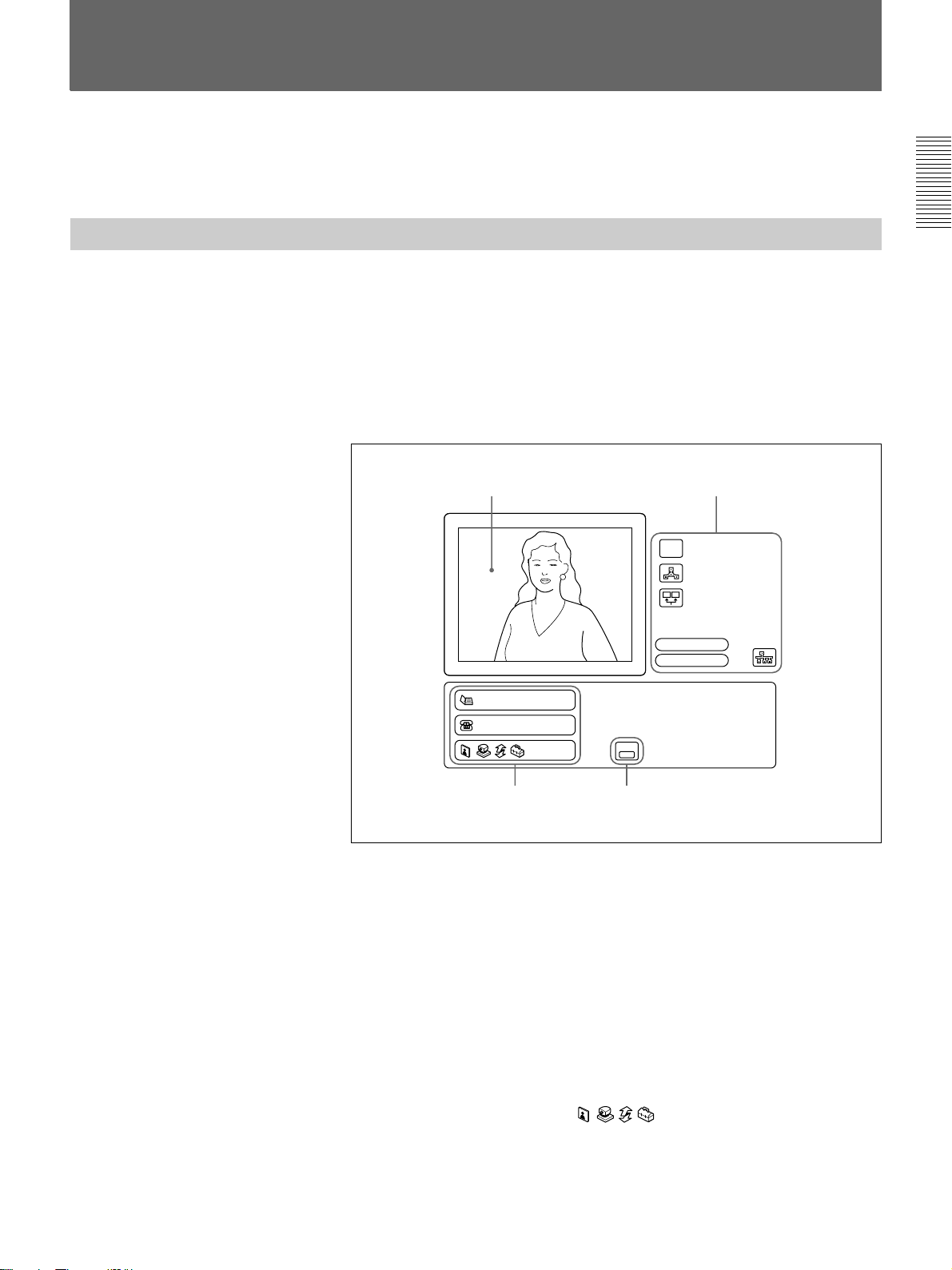
How to Operate the Menu
The different menu is opened whether the system is in communication or
not.
Switching the Menu Not in Communication
The following launcher menu is always displayed when the system is not
in communication. Select the desired menu with the joystick on the
Remote Commander, then press the joystick. The desired menu will be
opened.
Launcher menu
The following explains how to use the Launcher menu.
MIC
OFF
Audio:MIC
Video:Main
Chapter 1
41
Phone Book
Manual Dial
HELP
Press this and an explanation is
displayed.
2 3
1 The screen
The image captured by the local camera is displayed here. When you
select the screen using the joystick on the Remote Commander (the
screen border turns yellow), and press it down, you can then adjust the
camera angle up, down, left or right, with the joystick. In addition, if
you press the T-button on the Remote Commander ZOOM/TV-CH
button, the picture is enlarged; if you press the W-button, it is reduced
in size. Once you have the picture you want, pressing the joystick on
the Remote Commander ends the camera angle adjustment mode. For
more details on camera angle adjustment, see page 71.
2 Phone Book/Manual Dial/
You can toggle through the menus using the joystick. For an
explanation of each menu, see pages 49 through 50.
(Continued)
Chapter 1 Preparation 47
Page 48

How to Operate the Menu
Chapter 1
3 HELP
When you press the HELP button on the Remote Commander, an
explanation is provided for each menu. When you press the HELP
button again, the explanation disappears.
4 Icons
The following provides an explanation for each icon.
1
MIC
OFF
2
3
4
5
1 Mic mute function: When this icon is displayed, the sound from
2 Multipoint mode: This icon is displayed when the Multipoint
3 Dual monitor: This icon is displayed when the Dual monitor item
4 Audio input: This icon is displayed to show the audio input. To
5 Video input: This icon is displayed when video input is sent to a
6 LAN status: This item is displayed in blue when the LAN is
Audio:MIC
Video:Main
6
the local position will not be sent to remote parties. For more
details, see page 69.
mode is set to ON. For more details, see page 38.
in the General Setup menu is set to TV Monitor (Dual). For more
details, see page 39.
enable switching of the input, set the Audio Switching item in the
Audio settings. For more details, see page 77.
monitor. To switch the input, press the INPUT SELECT button on
the Remote Commander, then select input with the joystick. For
more details, see page 77.
available, and in red when it is not.
48 Chapter 1 Preparation
Page 49

Phone Book menu
Phone Book
Recent
0-9
A-I
J-S
T-Z
New Entry
This is used to hold a meeting
with a registered party or to
register or modify a party.
(Pressing the PHONE BOOK
button on the Remote Commander
accesses the Phone Book menu
directly.)
For details on the Phone Book menu, see pages 59 to 65.
Manual Dial menu
Manual Dial
A1:
A2:
A3:
A4:
A5:
A6:
Line I/F:
BRI
Number of Lines:
6B
Prefix:
Prefix-None
Restrict:
Auto
SaveDial
This is used to hold a meeting
with an unregistered party.
Chapter 1
For details on the Manual Dial menu, see pages 55 to 59.
Still Image menu
Still Image
Send
Continuous Send
Clear
Save
Load
Pointer
Send Object
For details on the Still Image menu, see pages 79 to 83.
This is used to control a still
image. (Pressing the STILL
IMAGE button on the Remote
Commander accesses the Still
Image menu directly.)
Camera Angle menu
Camera
Preset Save
Preset Load
Adjustments
Auto Track
This is used to control the angle
and zoom of the camera. (Pressing
the CAMERA button on the
Remote Commander accesses the
Camera Angle menu directly.)
For details on the Camera Angle menu, see pages 71 to 76.
Chapter 1 Preparation 49
Page 50

How to Operate the Menu
Data Conference menu
Chapter 1
Data Conference
File Access
Whiteboard
Whiteboard (.WHT)
D:\ ...\user
data
Specification.jpg
Messages.jpg
Messages2.jpg
T120demo.ppt
AGENDA with CMS...
DSC00000.jpg
TMP5000EMU.jpg
Used for a Data Conference.
For details on the Data Conference Menu, see pages 84 to 89.
Setup menu
Setup
Dial Answer
Multipoint Audio
General Administrator
ISDN LAN
Information Status
This is used to register or modify
the setup of the system.
For details on the Setup menu, see pages 21 to 23 and 32 to 46.
Note
If a BRI board, a PRI board, a V.35 board, an RS-449 board, or a LAN
software upgrade has not been installed, the Phone Book menu, the
Manual Dial menu, and the Setup menu cannot be opened.
50 Chapter 1 Preparation
Page 51

Switching the Menu in Communication
Press the STILL IMAGE button on the Remote Commander in
communication, the Still Image menu is opened. Select the desired menu
with the joystick on the Remote Commander, then press the joystick. The
desired menu will be opened.
Select these tabs
with the joystick to
access the desired
menu.
Select
to the previous
menu.
to return
Chapter 1
Still Image
Send
Continuous Send
Clear
Save
Load
Pointer
Send Object
Select these
buttons to select
the desired item.
The picture shot by the local
camera appears.
Still Image menu
Still Image
Send
Continuous Send
Clear
Save
Load
Pointer
Send Object
For details on the Still Image menu, see pages 79 to 83.
This is used to control a still
image. (Pressing the STILL
IMAGE button on the Remote
Commander accesses the Still
Image menu directly.)
Camera menu
Camera
Preset Save
Preset Load
Adjustments
Auto Track
This is used to control the camera.
(Pressing the CAMERA button on
the Remote Commander accesses
the Camera menu directly.)
For details on the Camera menu, see pages 71 to 76.
Chapter 1 Preparation 51
Page 52

How to Operate the Menu
Phone Book menu
Chapter 1
Phone Book
Recent
0-9
A-I
J-S
T-Z
New Entry
This is used to hold a meeting
with a registered party or to
register or modify a party. (Press
the PHONE BOOK button on the
Remote Commander.)
For details on the Phone Book menu, see pages 59 to 65.
Data Conference menu
Data Conference
File Access
Whiteboard
Whiteboard (.WHT)
D:\ ...\user
data
Specification.jpg
Messages.jpg
Messages2.jpg
T120demo.ppt
AGENDA with CMS...
DSC00000.jpg
TMP5000EMU.jpg
Used for a Data Conference. With
NetMeeting, you can use the file
forwarding, program sharing, and
whiteboard functions.
For details on the Data Conference Menu, see pages 84 to 89.
Setup menu
Setup
Dial Answer
Multipoint Audio
General Administrator
ISDN LAN
Information Status
For details on the Setup menu, see pages 21 to 23 and 32 to 46.
This is used to register or modify
the setup of the system.
52 Chapter 1 Preparation
Page 53

Operating the Menu
This describes the basic menu operation, taking the Dial Setup menu as an
example.
Chapter 1
1 Open the Dial Setup menu from the Setup menu (page 50).
Dial Setup
Page: 1/4
ISDNLine I/F:
AutoBonding:
6BNumber of Lines:
1024KbpsLAN Bandwidth:
Prefix-NonePrefix:
AutoRestrict:
CancelSave
2 Select the desired item with the joystick on the Remote Commander,
then press the joystick.
The settings of the selected item is pulled down.
Dial Setup
Page: 1/4
Line I/F:
Bonding:
Number of Lines:
LAN Bandwidth:
Prefix:
Restrict:
Auto
On
CancelSave
3 Select the desired setting with the joystick on the Remote Commander
moved up or down, then press the joystick.
4 Select Save with the Remote Commander, then press the joystick.
The modification is complete.
To page up or down the menu
Move the joystick on the Remote Commander to the right or left.
To return to the previous level hierarchy of the menu
Press the RETURN button on the Remote Commander.
Chapter 1 Preparation 53
Page 54

How to Operate the Menu
Turning Off the Indicators displayed on the screen
Chapter 1
Entering Characters
Press the DISPLAY button on the Remote Commander to turn off the
indicators displayed on the screen. To turn on the indicators, press it again.
Note
You cannot turn off all of the indicators, depending on the indicator.
12
4
7
10/0
DISPLAY
P
B
S
L
I
T
S
C
A
L
GHI
PQRS
n
i
C
A
P
M
I
E
L
P
K
E
C
A
R
A
E
G
ABC3 DEF
5
JKL
8
TUV
0
HELP
E
R
M
A
C
N
E
I
L
P
Y
O
C
6
9
VIDEO INPUT
SELECT
F
A
R
A
P
H
O
S
Y
MNO
WXYZ
/
N
E
A
R
A
L
P
H
A
/
N
U
M
N
E
B
O
O
K
M
B
O
L
Number buttons
PinP (BACK SPACE) button
FAR/NEAR (ALPHA/NUM) button
PHONE BOOK (SYMBOL) button
CAMERA (LINE COPY) button
STILL IMAGE (CLEAR) button
To switch the input mode
Press the FAR/NEAR (ALPHA/NUM) button on the Remote Commander
repeatedly to switch the input mode.
To enter characters
Press the number buttons on the Remote Commander to enter the desired
character. Each time you press the button, the character is input from
among the alphabets on each button, or the numbers on each.
To enter special characters (symbols), press the PHONE BOOK
(SYMBOL) button repeatedly to select a desired character.
54 Chapter 1 Preparation
To copy the number
Press the CAMERA (LINE COPY) button on the Remote Commander.
The number in the box above is copied to the next box.
To delete a character
Press the PinP (BACK SPACE) button on the Remote Commander. The
last entered character is deleted.
To delete all characters in a box
Move the cursor to the box where you want to delete the entry, then press
the STILL IMAGE (CLEAR) button on the Remote Commander.
Page 55

Basic Operation
During a Meeting
Calling a Remote Party
You can start a meeting with a remote party by dialing. Once you have
made a connection with the remote party, you can begin talking just like
normal phone call.
The following describes how to call a remote party.
Chapter 2
Chapter 2
You have to register your local system data and set up the Multimedia
Terminal before starting a meeting.
Notes
•Meetings using the V.35 interface are available when the optional PCSI602 V.35 board has been installed.
•Meetings using the RS-449 interface are available when the optional
PCS-I603 RS-449 board has been installed.
•Meetings on a LAN are available when the system has been upgraded
with the optional PCS-UC601 Upgrade Kit.
Calling an Unregistered Remote Party
The following launcher menu is always displayed on the monitor screen
not in communication.
MIC
OFF
Audio:MIC
Video:Main
Phone Book
Manual Dial
HELP
Press this and an explanation is
displayed.
Chapter 2 Basic Operation During a Meeting 55
Page 56

Calling a Remote Party
1 Select Manual Dial with the joystick on the Remote Commander, then
press the joystick, or press the CONNECT/DISCONNECT (
button on the Remote Commander.
The Manual Dial menu appears on the monitor screen.
Manual Dial
/ )
Chapter 2
A1:
A2:
A3:
A4:
A5:
A6:
Notes
Line I/F:
BRI
Number of Lines:
6B
Prefix:
Prefix-None
Restrict:
Auto
SaveDial
•The items above differ depending on the types of the boards which
has been installed.
•If a BRI board, a PRI board, a V.35 board, an RS-449 board, or a
LAN software upgrade has not been installed, the Manual Dial menu
cannot be opened.
2 Set up the line interface.
Select Line I/F with the joystick on the Remote Commander, then
press the joystick. Select the desired setting by moving the joystick up
or down, then press the joystick.
BRI: Connects to a TV conferencing system via the BRI interface.
PRI: Connects to a TV conferencing system via the PRI interface.
PRI-S: Connects to a TV conferencing system using H
America), H
12 (for European countries) of the PRI interface.
Telephone: Connects to a phone to have a voice meeting via the
normal ISDN line.
V.35: Connects to a TV conferencing system via the V.35 interface.
LAN: Connects to a TV conferencing system using a LAN.
RS-449: Connects to a TV conferencing system via the RS-449
interface.
0, H11 (for North
56 Chapter 2 Basic Operation During a Meeting
3 Enter the telephone number.
When connecting via the ISDN lines
Enter the telephone number of the remote party to have a meeting with
in the boxes.
Page 57

When connecting with the V.35 interface with RS-366
When using single channel, enter the telephone number in the A1 box.
When using dual channels, enter the telephone numbers in the A1 and
A2 boxes.
Note
When connecting with the V.35 interface without RS-366 or
connecting with the RS-499 interface, the telephone number boxes are
not displayed.
When connecting on a LAN
Enter the IP address (or host name and domain name) of the remote
party to have a meeting with in the IP Address box.
Move the joystick up or down to select the box, then enter the
telephone number or IP address with the number buttons on the
Remote Commander.
•To delete a telephone number or IP address, press the STILL IMAGE
(CLEAR) button on the Remote Commander. The number or IP
address entered is deleted.
•To copy a telephone number, press the CAMERA (LINE COPY)
button. The number entered are copied to the next box.
•To delete the last number, press the PinP (BACK SPACE) button on
the Remote Commander. The last number is deleted.
4 Select the prefix setting.
Select Prefix with the joystick on the Remote Commander, then press
the joystick. Select the desired setting by moving the joystick up or
down, then press the joystick.
Prefix-None: Does not use the prefix number.
Prefix-A: Uses the setting A set in the Dial Setup menu.
Prefix-B: Uses the setting B set in the Dial Setup menu.
Prefix-C: Uses the setting C set in the Dial Setup menu.
Chapter 2
Pressing the HELP button on the Remote Commander allows you to
check the prefix settings.
For details on the setting up the prefix number, see “Dial Setup Menu” on
page 32.
(Continued)
Chapter 2 Basic Operation During a Meeting 57
Page 58

Calling a Remote Party
Chapter 2
5 Select the ISDN transfer rate.
Select Restrict with the joystick on the Remote Commander, then press
the joystick. Select the desired setting by moving the joystick up or
down, then press the joystick.
Auto: Connects to a remote party with a normal ISDN line.
56K: Connects to a region or country with a 56 Kbps ISDN transfer
rate.
Note
When holding a meeting on a LAN, the Restrict item cannot be set.
6 Select Dial with the joystick on the Remote Commander, then press
the joystick, or press the CONNECT/DISCONNECT (
the Remote Commander.
The system dials the number that is input in step 2, and the indication
“Dialing (The line interface is indicated.)” appears on the monitor
screen.
When the connection is completed, the indication “MEETING
STARTS!” appears on the monitor screen.
/ ) button on
To cancel dialing before the connection is completed
Select Cancel with the joystick on the Remote Commander, then press the
joystick, or press the CONNECT/DISCONNECT (
Remote Commander.
To set up other items than the items above
When More Options Enable is set to On in the Dial Setup menu, the More
Options button is displayed at the lower part of the menu. Select More
Options with the joystick on the Remote Commander, then press the
joystick. The Dial Setup menu appears and you can set up the other items.
Notes
•Settings made for the Dial List from the More Options menu have
priority over those made from the Dial Setup menu.
•You cannot make settings for Audio Mode Threshold, Prefix, More
Option Enable, V.35 RS-366, or the 5000 Series Mode on the More
Options menu of the Dial List.
/ ) button on the
58 Chapter 2 Basic Operation During a Meeting
Page 59

Last-number redial function
When you access the Manual Dial menu again after you have used the
Manual Dial menu once, the last number dialed is entered into the boxes.
Notes
This function does not work in the following situations:
•Once you turned off the power or turned the Multimedia Terminal to
standby/sleep.
•You have not dialed to its number yet, though you entered the number.
Calling a Registered Remote Party
1 Press the PHONE BOOK button on the Remote Commander.
The Phone Book menu appears on the monitor screen.
Phone Book
Chapter 2
Recent
0-9
A-I
J-S
T-Z
New Entry
If a BRI board, a PRI board, a V.35 board, an RS-449 board, or a LAN
software upgrade hasn’t been installed, the Phone Book menu cannot
be opened.
2 Select the remote party with the joystick on the Remote Commander,
then press the joystick.
The sub-menu is opened on the monitor screen.
Phone Book
Recent
0-9
On
Dial
Edit
Copy
Delete
A-I
J-S
T-Z
New Entry
You can sort the list on the Phone Book menu.
For details, see “To sort the list on the Phone Book menu” on page 60.
(Continued)
Chapter 2 Basic Operation During a Meeting 59
Page 60

Calling a Remote Party
3 Select Dial with the joystick on the Remote Commander, then press
the joystick. Or press the CONNECT/DISCONNECT (
the Remote Commander.
The system dials the selected remote party in step 2, and the indication
“Dialing (The line interface is indicated.)” appears on the monitor
screen.
When the connection is completed, the indication “MEETING
STARTS!” appears on the monitor screen.
/ ) button on
Chapter 2
To sort the list on the Phone Book menu
To cancel dialing before the call is connected
Select Cancel with the joystick on the Remote Commander, then press the
joystick, or press the CONNECT/DISCONNECT (
/ ) button on the
Remote Commander.
You can sort the list on the Phone Book menu.
The list on the Phone Book menu will be sorted by selecting the buttons at
the right on the menu.
When you select Recent, most recently dialed six indexes are displayed.
When you select 0–9, A–I, J–S, or T–Z, and select the desired letter, six
indexes which start from the specified letter are displayed.
Phone Book
Recent
0-9
A-I
J-S
T-Z
New Entry
J
K
L
M
N
O
P
Q
R
S
60 Chapter 2 Basic Operation During a Meeting
Page 61

Registering a Remote Party
You can register a remote party before making the connection. You can
register up to 500 remote parties.
Notes
•Meetings using the V.35 interface are available when the optional PCSI602 V.35 board has been installed.
•Meetings using the RS-449 interface are available when the optional
PCS-I603 RS-449 board has been installed.
•Meetings on a LAN are only available when the system has been
upgraded with the optional PCS-UC601 Upgrade Kit.
•A meeting can only be held over ISDN if a BRI or a PRI board has been
installed.
Making an Entry
1 Press the PHONE BOOK button on the Remote Commander.
The Phone Book menu appears on the monitor screen.
Chapter 2
Phone Book
Recent
0-9
A-I
J-S
T-Z
New Entry
2 Select New Entry with the joystick on the Remote Commander, then
press the joystick.
The List Edit menu appears on the monitor screen.
List Edit
Index:
A1:
A2:
A3:
A4:
A5:
A6:
BRI
Line I/F:
BRI
Number of Lines:
6B
Prefix:
Prefix-None
Restrict:
Auto
CancelSave
3 Register the name of the remote party into the Index box.
For details on how to input, see “Entering Characters” on page 54.
Chapter 2 Basic Operation During a Meeting 61
(Continued)
Page 62

Registering a Remote Party
Chapter 2
4 Set up the line interface.
BRI: Connected to a TV conferencing system using BRI interface.
PRI: Connects to a TV conferencing system via the PRI interface.
PRI-S: Connects to a TV conferencing system using H
America), H
Telephone: Connects to a phone to have a voice meeting via the
normal ISDN line.
V.35: Connects to a TV conferencing system via the V.35 interface.
LAN: Connects to a TV conferencing system using a LAN.
RS-449: Connects to a TV conferencing system via the RS-449
interface.
12 (for European countries) of the PRI interface.
0, H11 (for North
5 When connecting via the ISDN lines
Enter the telephone number and the sub-address for the remote party
(if the remote party set a sub-address) in the A1 and A2 boxes.
If the remote party is using multiple lines, enter the telephone numbers
in the B1/B2 and subsequent boxes.
Enter the asterisk (
address. You cannot use the alphabet in a sub-address.
) after the telephone number, then enter the sub-
When selecting PRI-S in step 4, only the A1 box is displayed. Enter
the telephone number in the A1 box.
When connecting on a LAN
Enter the IP address (or host name and domain name) of the remote
party.
When connecting with the V.35 interface with RS-366
When using single channel, enter the telephone number in the A1 box.
When using dual channels, enter the telephone numbers in the A1 and
A2 boxes.
Note
When connecting with the V.35 interface without RS-366 or
connecting with the RS-449 interface, the telephone number boxes are
not displayed.
6 Select the line interface icons.
Move the joystick to the left or right to select the icon, then press the
joystick.
62 Chapter 2 Basic Operation During a Meeting
Page 63

7 Select the prefix number setting.
Prefix-None: Does not use the prefix number.
Prefix-A: Uses the setting A set in the Dial Setup menu.
Prefix-B: Uses the setting B set in the Dial Setup menu.
Prefix-C: Uses the setting C set in the Dial Setup menu.
For details on setting the prefix number, see “Dial Setup Menu” on page 32.
8 Select the ISDN transfer rate.
Auto: Connects to a remote party with a normal ISDN line.
56K: Connects to a region or country with a 56 Kbps ISDN transfer
rate.
9 Select Save with the joystick on the Remote Commander, then press
the joystick.
The registration is complete.
Note
When using a LAN, item below cannot be set up:
Restrict.
To set up other items than the items above
When More Options Enable is set to On in the Dial Setup menu, the More
Options button is displayed at the lower part of the menu. Select More
Options with the joystick on the Remote Commander, then press the
joystick. The Dial Setup menu appears and you can set up the other items.
Notes
•More Options has a higher priority than the Dial Setup menu.
•You cannot make settings for the Audio Mode Threshold, Prefix, More
Option Enable, V.35 RS-366, or the PCS-5000 Series Mode on the More
Options menu of the Dial List.
Chapter 2
Modifying an Entry
You can modify the name and telephone numbers of an entry.
1 Select the Index title to be modified with the joystick, then press the
joystick.
2 Select Edit with the joystick on the Remote Commander, then press the
joystick.
The List Edit menu appears.
(Continued)
Chapter 2 Basic Operation During a Meeting 63
Page 64

Registering a Remote Party
3 Modify the entry.
4 Select Save with the joystick on the Remote Commander, then press
Deleting Registered Entries
the joystick.
The entry is modified.
Chapter 2
You can delete a registered entry as follows.
1 Select the Index title to be deleted with the joystick on the Remote
Commander.
2 Select Delete with the joystick on the Remote Commander, then press
the joystick.
The selected Index entry is deleted.
Duplicating the Setting of the Phone Book Menu
1 Select the index to be copied with the joystick on the Remote
Commander, then press the joystick.
2 Select Copy with the joystick on the Remote Commander, then press
the joystick.
The index is duplicated, and “XXXX-2” appears in the Index box.
Since the setting has been duplicated, you can use it with a little
modification.
Notes on Registration
64 Chapter 2 Basic Operation During a Meeting
General note
If the Restrict setting of the remote party is set to 56K in the Answer Setup
menu, the connection will be made at 56 Kbps even if you set Restrict to
Auto in the Dial Setup menu.
Note on the optional PCS-I600 BRI Board
If you have installed the multiple PCS-I600 BRI Boards, you can use
twelve ISDN lines (up to 24B channels). In this case, register second
telephone number downward in the boxes B1/B2 or downward, you can
connect with up to 6B channels. When you connect with 8B channels or
more, the connection uses the bonding interface. In this case, register the
telephone number only in the box A1. The connection is up to 24B
channels according to the number of channels set in Number of Lines.
When you install the PCS-I601 PRI Board and set Line I/F to PRI, the
connection via 8B-channel or more is the Bonding connection.
Page 65

Note on the optional PCS-I602 V.35 Board
If the optional PCS-I602 V.35 Board has been installed and connected to a
private line or a terminal adaptor via the V.35 interface, select V.35 in
Line I/F then enter as follows:
• When using RS-366, set V.35 RS-366 to On in the Dial Setup menu.
Enter the telephone numbers.
• When not using RS-366, set V.35 RS-366 to Off in the Dial Setup menu.
Do not enter the telephone numbers.
• You do not need to set up Restrict.
To change the ISDN transfer rate temporarily
The Multimedia Terminal is set to 64 Kbps for an ISDN line at factory.
However, some countries (e.g., the USA) or regions may have 64 Kbps
and 56 Kbps ISDN transfer rates. If the remote party has set its transfer
rate to 56 Kbps, you need to set your system to 56 Kbps to communicate
with that system.
Before making a call to such a party, set Restrict to 56K in the Dial Setup
menu.
Chapter 2
Chapter 2 Basic Operation During a Meeting 65
Page 66

Chapter 2
Receiving a Call
When a call comes in, the connection process differs depending on the
setting of the answer mode.
Auto answer mode
The system automatically receives the call and starts the meeting.
However, even if you are not ready to start the meeting, the local picture
will be displayed on the remote party’s monitor screen.
Manual answer mode
Incoming calls are not automatically connected. You must manually
connect the call.
You can start the meeting whenever you are ready.
Notes
•The I/1 switch of the Multimedia Terminal Processor must be set to on
to receive a call.
•Make sure that the TV monitor is on standby when using a TV monitor.
•Make sure that the RGB monitor or LCD projection data monitor is
turned on when using an RGB monitor or LCD projection data monitor.
Setting the Answer Mode
When you select the auto answer mode, set Auto Answer to On in the
Answer Setup menu. When you select the manual answer mode, set it to
Off.
For details on the Auto Answer item, see “Answer Setup Menu” on page 36.
Answering Calls in Auto Answer Mode
The system automatically receives a call when it is on standby or in sleep
mode.
When a call comes in, the Multimedia Terminal starts ringing, and the
indication “Incoming Call” appears on the monitor screen.
Once the connection has been made, the remote party appears on the local
monitor screen, and the local party appears on the remote screen. You are
now ready to hold your meeting.
The indication “MEETING STARTS!” appears on the monitor screen.
Answering Calls in Manual Answer Mode
When your system is in manual answer mode, you need to connect
incoming calls manually.
When a call comes in, the Multimedia Terminal starts ringing, and the
indication “Incoming Call. Respond?” appears on the monitor screen.
66 Chapter 2 Basic Operation During a Meeting
Page 67

Select OK with the joystick on the Remote Commander, then press the
joystick, or press the CONNECT/DISCONNECT (
Remote Commander.
Once the connection has been made, the remote party appears on the local
monitor screen, and local party appears on the remote screen. You are now
ready to hold your meeting.
The indication “MEETING STARTS!” appears on the monitor screen.
If you do not want to receive a call
Select Cancel with the joystick, then press the joystick. The Multimedia
Terminal stops ringing.
If you are operating the system when a call comes in
The indication “Incoming Call. Respond?” appears on the monitor screen.
If you receive the call, Select OK with the joystick on the Remote
Commander, then press the joystick. If you cannot receive the call
according to your current operations, Select Cancel with the joystick on
the Remote Commander, then press the joystick.
/ ) button on the
Chapter 2
When the system fails to make a connection
The indication “CANNOT COMPLETE CONNECTION” appears along
with an ISDN cause code and a message on the monitor screen.
For details on ISDN cause codes and messages, see “On Screen Messages” on
page 124.
When the optional PCS-UC601 Upgrade Kit has been installed
If a call comes in via the ISDN line during the meeting on a LAN, the
Multimedia Terminal cannot receive the call since the unit is busy.
When connected over ISDN
When a call request comes in over a LAN while you are connected over
ISDN, this unit will refuse to accept the call, even if you have installed the
optional LAN software upgrade.
Chapter 2 Basic Operation During a Meeting 67
Page 68

Chapter 2
Checking the Connection Status
During a meeting, you can check the status of the communication. Elapsed
time also appears on the monitor screen during a meeting.
1 Open the Status menu.
Status
Page: 1/3
Line I/F: Camera Control:
Rate: Data Control:OnOff
Audio Mode: LSD Rate:
Video Mode: MLP Rate:
Frame Rate:
2 Check the status:
Line I/F: Displays the line interface being used.
Rate: Displays the number of lines and the transfer rate being used.
Camera Control: Displays the far end camera control protocol.
Data Control: Displays the data transmission protocol.
BRI
2 x 64K
G.728
H.261 CIF
15fps
G.728
H.261 CIF
15fps HMLP Rate:
(Encode)(Decode)(Encode) (Decode)
6400
6400
Off
Off
Off
Off
End
On elapsed time
The items below are separately displayed in the columns Encode and
Decode.
The columns Encode indicate the status being sent, the columns
Decode indicate the status being received.
Audio Mode: Displays the audio encoding system.
Video Mode: Displays the video encoding system.
Frame Rate: Displays the maximum frame rate of the motion picture.
LSD Rate: Displays the LSD (Low Speed Data) rate.
MLP Rate: Displays the MLP (Multi Layer Protocol) rate.
HMLP Rate: Displays the HMLP (High speed Multi Layer Protocol)
rate.
To close the Status menu
Select End with the joystick on the Remote Commander, then press the
joystick. The menu returns to the Setup menu.
When you set Time Display to On in the General Setup menu, the elapsed
time appears on the monitor screen during a meeting. You can use it as a
guide, and it is convenient for checking communication costs. If you do
not need to display the elapsed time, set Time Display to Off.
68 Chapter 2 Basic Operation During a Meeting
For details on the Time Display setting, see “General Setup Menu” on page 39.
Page 69

Adjusting the Sound
Adjusting the Volume
You can adjust the volume sent from remote parties.
Press the VOLUME/DOC-BRIGHT + button to increase the volume; the
VOLUME/DOC-BRIGHT – button to decrease it.
The volume bar appears on the monitor screen.
After a while, the bar automatically disappears if you do not operate.
Notes
• You have to set the volume of the monitor at first.
• If feedback occurs, decrease the volume.
Muting Local Conversations – Mute Function
Chapter 2
You can mute local conversations.
If you press the MIC/DOC-DARK button, local conversations will not be
sent to the remote party.
When local conversations are muted, the mute indication
the monitor screen.
To cancel muting
Press the MIC/DOC-DARK button on the Remote Commander again.
MIC
OFF
The mute indication
disappears from the monitor screen.
Synchronizing Voice and Motion – Lip Synchronization
During the meeting, voice and motion may lose synchronization.
The automatic lip synchronization function built into the system solves this
problem by closely synchronizing audio and video before they are
transmitted to the remote party.
When you use the lip synchronization, set Lip Sync to On in the Audio
Setup menu. When you do not use the lip synchronization, set it to Off.
For details on the Lip Sync setting, see “Audio Setup Menu” on page 39.
MIC
OFF
is displayed on
Note
The lip synchronization function only works for your own party. To
activate the lip synchronization function at the remote party, you must ask
them to do so.
Chapter 2 Basic Operation During a Meeting 69
Page 70

Adjusting the Sound
On the Echo canceler
Chapter 2
The Multimedia Terminal has an echo canceler function. When you use
this built-in echo canceler, set Echo Canceler to Internal in the Audio
Setup menu. When you are not using the internal echo canceler, set this
item to Off. When you use the echo canceler of equipment connected to
AUDIO IN AUX, set it to External. Normally, it should be set to Internal.
Echo canceler Input setting Internal echo canceler Mic off
Internal MIC Enabled Valid
External AUX Disabled (bypass) Invalid
Off MIC Disabled (bypass) Valid
For details on the Echo Canceler setting, see “Audio Setup Menu” on page 39.
Notes
• When Input setting is set to MIC, MIC IN and AUDIO LINE IN are
selected.
• When Input setting is set to AUX, AUDIO IN AUX is selected.
70 Chapter 2 Basic Operation During a Meeting
Page 71

Adjusting the Camera
You can adjust the local camera to obtain the best viewing results.
During communication, you can also adjust the remote camera, and adjust
images being sent from the remote camera.
Notes
•A malfunction may occur if the local and remote parties try to adjust the
same camera at the same time.
•You cannot control the remote camera during a meeting if H.281 is not
selected as the far end camera control protocol.
•You cannot control the remote camera during a meeting if the Multimedia
Terminal is used as the multipoint terminal.
•When you operate a remote camera, you cannot control backlight,
brightness, and automatic adjustment of the focus and brightness.
To display the picture on the whole screen
When you adjust the camera, press the PinP button on the Remote
Commander. The picture will be displayed on the whole screen. To return
to the previous screen, press the joystick, the RETURN button, or the PinP
button on the Remote Commander.
Chapter 2
To select the camera to be adjusted
Before adjusting the camera, you must select the local or remote camera to
be controlled.
1 Press the FAR/NEAR button on the Remote Commander.
The Display Control menu appears.
2 Select the far or near camera from Control with the joystick on the
Remote Commander, then press the joystick.
When the remote camera is selected, the indication [FAR] appears on the
monitor screen.
When the local camera is selected, the indication [FAR] does not appear on
the monitor screen.
Note
You cannot control the remote camera if you do not set Far End Camera
Control to On in the Dial Setup menu at the local, and set Far End Camera
Control to On in the Answer Setup menu at the remote and set Control by
Far End to On in the General Setup menu at the remote.
Display Control
Display
Far
Control
Near
Chapter 2 Basic Operation During a Meeting 71
Page 72

Adjusting the Camera
Adjusting the Camera Angle and Zoom
To adjust the camera angle
Chapter 2
You can adjust the camera angle and zoom.
Move the joystick on the Remote Commander up, down, to the left, or to
the right to view any areas not currently covered by the camera. (Select
Camera Angle from the launcher menu to open the Camera Angle menu
when the system is not in communication.)
Outside the camera’s scope
Within the camera’s scope
To adjust zoom
Press the ZOOM/TV-CH T button on the Remote Commander to zoom in
or the ZOOM/TV-CH W button to zoom out. Adjust zoom to display the
desired picture.
Adjusting Focus and Brightness
Focus and brightness are automatically adjusted.
We recommend that you do not use the manual adjustments since the
camera automatically adjust itself for the best focus and brightness.
Select Adjustment with the joystick on the Remote Commander in the
Camera menu, then press the joystick. The guidance will appear and you
can adjust the focus and brightness.
72 Chapter 2 Basic Operation During a Meeting
Page 73

To adjust focus manually
Press the [0] button on the Remote Commander, the focus adjustment
setting changes to automatic adjustment.
Press the [#t] button on the Remote Commander repeatedly to move the
focus point further away to the camera.
Press the [*T] button on the Remote Commander repeatedly to move the
focus point closer to the camera.
To adjust brightness
Press the [9] button on the Remote Commander repeatedly to make the
picture brighter.
Press the [7] button on the Remote Commander repeatedly to make the
picture darker.
To shoot with the backlight function
When you shoot a subject with the light source behind the subject, use the
backlight function.
Each time you press the [8] button or the MIC/DOC-DARK button on the
Remote Commander, the backlight function toggles on and off.
Presetting Angle and Zoom Settings
You can store the camera settings in memory up to six presets, and each
preset has the angle and zoom settings.
Once a setting has been stored, you can easily recall a setting from the six
presets.
Chapter 2
To store a setting
1 Open the Camera menu.
2 Select Preset Save with the joystick on the Remote Commander, then
press the joystick.
(Continued)
Chapter 2 Basic Operation During a Meeting 73
Page 74

Adjusting the Camera
3 Select the preset number which you want to store the setting with the
joystick on the Remote Commander, then press the joystick.
Chapter 2
Camera
Preset Save
Preset Load
Adjustments
Auto Track
1
2
3
4
5
6
4 Set up the angle and zoom.
For details on the angle and zoom settings, see “Adjusting the Camera Angle
and Zoom” on page 72.
5 Press the joystick on the Remote Commander.
The setting will be stored under the selected number.
Hint
If you press and hold any of the buttons from 1 through 6 on the
Remote Commander during a communication session, or if you
continue to press the # and any button from 1 to 6, you can store that
number as the preset value.
To recall a preset
1 Select Preset Load with the joystick on the Remote Commander, then
press the joystick.
2 Select the number button (1 to 6) with the joystick on the Remote
Commander, then press the joystick.
The camera is automatically adjusted by the preset under the selected
number.
Camera
Preset Save
Preset Load
Adjustments
Auto Track
1
2
3
4
5
6
74 Chapter 2 Basic Operation During a Meeting
Page 75

Hint
If you press any of the buttons from 1 through 6 on the Remote
Commander during a communication session, you can call up the value set
for that number.
On backup
The memories of the preset are erased when the I/1 switch on the
Multimedia Terminal Processor is set to off. To retain those memories, set
the BACKUP switch at the rear of the Camera Unit to ON.
Notes
•In the Camera Unit, the built-in lithium battery acts as the power source
for retaining the memories and is kept charged as long as the system is
used. However, if the system is used for shorter period of time with the
BACKUP switch set to ON, the battery is gradually discharged. If you do
not use the system at all for almost 12 weeks, the battery is completely
discharged. To retain the memories of the settings, you should recharge
the battery.
•To recharge the battery, connect the Camera Unit to the Multimedia
Terminal Processor and leave it for approximate 48 hours with the I/1
switch set to on.
Chapter 2
Tracking a Subject Automatically — Automatic Target Tracking Function
You can have the camera memorize a particular color or brightness so that
it automatically tracks a subject having the memorized color or brightness.
If a subject almost goes off the screen, the camera performs the pan/tilt
action so that the subject is placed back in the middle of the screen.
Note
The automatic target tracking function is only available for the local
camera.
1 Open the Camera menu.
2 Select Auto Track with the joystick on the Remote Commander, then
press the joystick.
The frame appear on the monitor screen.
Camera
Preset Save
Preset Load
Adjustments
Auto Track
(Continued)
Chapter 2 Basic Operation During a Meeting 75
Page 76

Adjusting the Camera
3 Use the joystick and the ZOOM/TV-CH buttons on the Remote
Commander to place a subject into the frame.
Notes
• Be sure to place the subject so that the portion uniform in brightness
and color is in the frame.
• The camera might not recognize a subject if the portion different
from the subject in brightness and color, such as the backdrop, is
placed together in the frame.
4 Press the joystick on the Remote Commander.
Chapter 2
To cancel the automatic target tracking function
Select Auto Track Stop with the joystick on the Remote Commander, then
press the joystick.
If the frame is repeatedly extended to the full screen
The camera does not recognize the subject. Repeat steps 2 to 4 again.
If the lamp at the side of the lens lights up
The camera is not capturing the memorized subject correctly.
In this case, perform the pan/tilt operation so that the subject comes into
the screen, or have the subject memorized onto the camera again.
Note
When the frame does not track the subject, repeat steps 2 to 4 until the
frame starts tracking the subject while adjusting the lighting and the
portion of the subject so that the color and brightness of the subject is
optimized.
76 Chapter 2 Basic Operation During a Meeting
Page 77

Selecting the Picture and Sound
You can select the picture and sound from both the local and remote sites
equipment.
To switch the picture
To switch the picture displayed on the monitor from the local
or remote picture
Press the FAR/NEAR button on the Remote Commander, then switch the
picture by selecting the icons on the monitor screen with the joystick on
the Remote Commander.
To switch the video that will be sent to the remote sites
Press the VIDEO INPUT SELECT button on the Remote Commander to
switch the picture on the screen.
Main: The Camera Unit is selected.
Object: The equipment connected to the VIDEO IN OBJECT jack is
selected.
AUX1: The equipment connected to the VIDEO IN AUX 1 jack is
selected.
AUX2: The equipment connected to the VIDEO IN AUX 2 jack is
selected.
Chapter 2
To switch the sound
To switch the video sent from the remote terminal
Press the VIDEO INPUT SELECT button on the Remote Commander,
then select Main/Object/AUX1/AUX2 from Far.
Note
You cannot control the remote camera during a meeting if H.281 is not
selected as the far end camera control protocol.
Set Input Select in the Audio Setup menu as follows:
MIC: The microphone is selected.
AUX: When you input voice from external equipment connected to
AUDIO IN AUX.
MIC + AUX: When you input voice from external equipment connected
to both AUDIO IN AUX and MIC.
For details on the Input Select item, see “Audio Setup menu” on page 39.
Note
The audio input of the remote cannot be switched from the local system.
Chapter 2 Basic Operation During a Meeting 77
Page 78

Chapter 2
Monitoring Yourself in the Inset Window
The inset window allows you to monitor your own party while viewing the
remote party. (Picture-in-picture function)
Press the PinP button on the Remote Commander in communication.
If an inset window is not displayed, the inset window appears on the
monitor screen.
When it is already displayed, each time you press the PinP button, the inset
window moves as follows:
3
Monitor screen
4
12
The inset window
disappears.
Notes
•The inset window is displayed at the same position as it was displayed
last. If the inset window is not displayed last, it is not displayed.
•The inset window does not appear when your system is not connected to
a remote party.
78 Chapter 2 Basic Operation During a Meeting
Page 79

Sending Still Pictures
When you send pictures that contain lots of text, we recommend you to
send that picture as a still picture. Since still pictures are more clear than
moving pictures for reading text.
You can send a video as a still picture of external equipment connected to
the Multimedia Terminal, or of the camera.
You can also send pictures continuously.
To display the still picture on the whole screen
When you display the still picture on the whole screen, press the PinP
button on the Remote Commander. The still picture will be displayed on
the whole screen. To return to the previous screen, press the joystick, the
RETURN button, or the PinP button on the Remote Commander.
Sending One Still Picture
1 Open the Still Image menu.
2 Select Send with the joystick on the Remote Commander, then press
the joystick.
Chapter 2
3 Set up the angle and zoom if you readjust them.
For details on the angle and zoom settings, see “Adjusting the Camera Angle
and Zoom” on page 72.
4 Press the joystick on the Remote Commander.
The moving picture on the monitor screen is frozen, and the still
picture is sent. After the transmission, the message “Transmission of
the still picture is sent” appears.
If Far End Camera Control is set to On at both the near and far end,
and the remote party’s screen is selected using the FAR/NEAR button
on the Remote Commander, the still picture of the remote party is sent
to the near side.
To clear the still picture from the screen
Select Clear with the joystick on the Remote Commander, then press the
joystick. Pressing the FAR/NEAR button on the Remote Commander also
clears it.
Note
When Video Mode is set to H.263, this function may not work depending
on the remote terminal.
Sending Still Pictures Continuously
1 Open the Still Image menu.
2 Select Continuous Send with the joystick on the Remote Commander,
then press the joystick.
(Continued)
Chapter 2 Basic Operation During a Meeting 79
Page 80

Sending Still Pictures
Chapter 2
Sending an Image from an Object Camera
3 Set up the angle and zoom if you readjust them.
For details on the angle and zoom settings, see “Adjusting the Camera Angle
and Zoom” on page 72.
4 Press the joystick on the Remote Commander.
The moving picture on the monitor screen is frozen, and the still
picture is continuously sent.
To cancel sending still pictures
Select Stop with the joystick on the Remote Commander, then press the
joystick.
Note
The interval to send still pictures varies depending on the communication
speed.
1 Press the STILL IMAGE button on the Remote Commander; the Still
Image menu appears.
2 Select Send Object with the joystick on the Remote Commander, then
press the joystick.
The image from the object camera is sent to the remote party. When
the system finishes sending the picture, the system displays the original
input image.
Sending a File Stored in the Hard Disk etc., As the Still Picture
Notes
•The files created in the JPEG format and have the “.jpg” extension are
available on this function.
•When the file name is too long, the characters not displayed are indicated
as “...”.
1 Press the STILL IMAGE button on the Remote Commander; the Still
Image menu appears.
80 Chapter 2 Basic Operation During a Meeting
Page 81

2 Select the Load with the joystick on the Remote Commander, then
press the joystick.
The following screen appears.
Still Image
Send
Continuous Send
Clear
Save
Previous Picture
Pointer
Send Object
D:\ ...\user\data
1300_01.jpg
40i_02.jpg
40i_03.jpg
IMG_7174.jpg
IMG_7765.jpg
IMG_8218.jpg
IMG_9792.jpg
s1_01s.jpg
3 Select the desired file with the joystick on the Remote Commander,
then press the joystick.
The still image is displayed.
4 Select Send with the joystick on the Remote Commander, then press
the joystick.
Chapter 2
5 Press the joystick on the Remote Commander.
The selected still picture is sent.
D:\...\user\data: the directory of the internal hard disk drive
(E): the directory of the CD-ROM
(F): the directory of the “Memory Stick”
Storing the Still Picture Sent From the Remote Party As the JPEG format
1 Open the Still Image menu after receiving a still picture.
2 Select Save with the joystick on the Remote Commander, then press
the joystick.
3 Select the desired location where the still picture will be stored with
the joystick on the Remote Commander, then press the joystick.
The still picture is stored.
Notes
•The file name is saved in the numerical order from DSC00000.jpg.
•When editing a file, select File Access from the Data Conference menu.
For details, see “Editing the File” on page 87.
Chapter 2 Basic Operation During a Meeting 81
Page 82

Sending Still Pictures
Displaying the Pointer or Drawing on Pictures
Chapter 2
When the remote party uses the PCS-5000/5000P/5100/5100P, you can
display the pointer or write over a still picture, and send or receive the
modified data. Drawing on pictures can be done only with a mouse (not
supplied).
Also, you can store the modified data as the JPEG format file.
Note
Set PCS-5000 Series Mode to On in the Dial Setup menu and Answer
Setup menu to use this function.
For details on the PCS-5000 Series Mode setting, see “Dial Setup Menu” on page
32 and “Answer Setup Menu” on page 36.
1 Open the Still Image menu.
2 Select the Pointer with the joystick on the Remote Commander, then
press the joystick.
The camera picture is frozen, and the picture is sent to the remote
party. Then, the following menu appears.
Pen
Erase
Save
Exit
If the remote party’s screen is selected using the FAR/NEAR button on
the Remote Commander, the still picture of the remote party is sent to
the near side.
3 Select the pointer icon with the joystick on the Remote Commander,
then press the joystick.
The pointer is displayed on the still picture.
4 Move the pointer by controlling the mouse.
82 Chapter 2 Basic Operation During a Meeting
5 Select the pen icon with the mouse.
6 Select the line thickness and the color with the mouse.
Select the color from green, red, or white.
Select the line thickness from thick, medium, or fine.
7 Write using the mouse.
Page 83

To erase a line
Select the eraser icon with the mouse. Trace the mouse along the lines or
words you want to erase.
To erase all the lines
Select Erase with the mouse. All the lines drawn with the mouse will be
erased.
To store the still picture modified with the mouse
Select Save with the mouse. The modified still picture will be stored. The
file is stored in the following directory: D:\...\user\data
To end a drawing or pointing
Select Exit with the mouse. The modified still picture will be automatically
stored.
To recall a saved image
Select Exit with the mouse, then display the Still Image menu and select
Read.
Chapter 2
Chapter 2 Basic Operation During a Meeting 83
Page 84

Chapter 2
Holding a Data Conference
You can use the files created by Microsoft Word, Microsoft Excel, or
Microsoft PowerPoint. The Multimedia Terminal opens these files using
the viewer application, and these files can be reffered each other. Since the
data conference use NetMeeting, you can use its program sharing function,
and you can transmit a file and use the white board.
Notes
•Set T.120 Data to On in the Dial Setup menu and Answer Setup menu to
use this function.
•You cannot hold a data conference:
– When connecting using the V.35 or RS-449 interface.
•You may not be able to hold a data conference depending on the remote
system.
•The color of the screen may be strange when using the program sharing
function. To view the file in the same color, transmit the file to the
remote terminal and open the file at the remote terminal.
You cannot hold a data conference while a conference using an MCU is
in progress.
•USB equipment, such as an USB keyboard, USB mouse, should be
required as follows:
– For Windows 2000 professional
– The total current of the connected USB devices is less than 0.5 A
including rush-current (Except the external power supply devices).
–When using the PCS-E600 Extention Hub, the USB device should
allow to access via 2 stage hub.
Opening the File
For details on the T.120 Data setting, see “Dial Setup Menu” on page 32 and
“Answer Setup Menu” on page 36.
You can use the files stored in the hard disk, “Memory Stick” that is
inserted in the Desktop Terminal, or floppy disk that is inserted in a USB
floppy disk drive.
Notes
•The files which have the following extensions are available on this
system:
“.jpg”, “.doc”, “.xls”, “.ppt”, “.pdf”, “.nmw”, “.wht”
•“.jpg” indicates the file created in the JPEG format.
•“.doc” indicates the file created by Microsoft Word.
•“.xls” indicates the file created by Microsoft Excel.
•“.ppt” indicates the file created by Microsoft PowerPoint.
•“.pdf” indicates the file created in the PDF format.
•“.nmw” indicates the file created by NetMeeting ver. 3.01.
•“.wht” indicates the file created by NetMeeting ver. 2.11.
•When the file name is too long, the characters not displayed are indicated
as “...”.
•Do not remove the “Memory Stick” while its directory is displayed on the
screen.
84 Chapter 2 Basic Operation During a Meeting
Page 85

The Multimedia Terminal is set to share the directory in the internal hard
disk drive on Microsoft Windows Network. The Windows OS PCs on the
same LAN can read and write the file.
The work group and computer names on Microsoft Windows Network are
as follows:
Work group: WORKGROUP
Computer: the name entered in Host Name in the LAN Setup menu.
The user name and password to share the file are as follows:
User name: ADMINISTRATOR
Password: (This is not set up.)
For details, consult a person having charge of your network.
The user available folder is only “user\data”. Be careful not to access
another folder or file.
1 Display the Data Conference menu.
2 Select File Access with the joystick on the Remote Commander, then
press the joystick.
The following menu appears.
Chapter 2
Data Conference
File Access
Whiteboard
Whiteboard (.WHT)
D:\ ...\user
data
Specification.jpg
Messages.jpg
Messages2.jpg
T120demo.ppt
AGENDA with CMS...
DSC00000.jpg
TMP5000EMU.jpg
3 Select the desired still picture with the joystick on the Remote
Commander, then press the joystick.
The following sub-menu appears.
Data Conference
File Access
Whiteboard
Whiteboard (.WHT)
Specification.jpg
Messages.jpg
Messages2.jpg
T120demo.ppt
AGENDA with CMS...
DSC00000.jpg
TMP5000EMU.jpg
DSC00001.jpg
DSC00002.jpg
Open
Share
Send
Copy
Paste
New
Delete
Rename
(Continued)
Chapter 2 Basic Operation During a Meeting 85
Page 86

Holding a Data Conference
4 Select Open with the joystick on the Remote Commander, then press
the joystick.
After the file opens, the task bar will appear on the upper portion, and
the bar at the left of the file extension turns on yellow. When the file is
shared from the remote party, its extension is indicated as “ETC”.
The file being displayed on the screen
JPG DOC XLS PPT PDF NMW WHT ETC
Return
Chapter 2
Files being opened
5 Select Return with the joystick on the Remote Commander, then press
the joystick.
The Data Conference menu appears again.
6 When the file opened in step 4 is to be shared, open its sub menu and
select Share with the joystick on the Remote Commander, then press
the joystick.
The selected image is displayed both on the local and remote
terminals.
7 When you open another image, repeat steps 3 to 6.
To switch the file displayed on the screen
Select the file extension indication of the desired file in the task bar with
the joystick on the Remote Commander, then press the joystick.
To return to the Data Conference menu
Select Return with the joystick on the Remote Commander, then press the
joystick.
86 Chapter 2 Basic Operation During a Meeting
Note
You can open files up to seven at the same time, however, you can open
only one file on the same extension.
To send the file
In step 4, select Send with the joystick on the Remote Commander, then
press the joystick. The selected file will be transmitted to the reomote
party. The files that not have the available extensions will not be saved
after transmission. The process is indicated on the local and remote screens
during sending/receiving the file. However, these indications may be
shifted in time.
Page 87

Editing the File
When receiving a file
The message “File receiving is complete.” is indicated. When opening the
Data Conference menu, its pop-up menu opens.
To save the file
Select Save, OK with the joystick on the Remote Commander in order,
then press the joystick. The destination location is D:\...\user. To not save
the file, select Delete from the pop-up menu.
To end the data conference
Select Return with the joystick on the Remote Commander, then press the
joystick. The Data Conference menu appears. The shared file is indicated
, and the opened file is indicated as . Select Close with the joystick
as
on the Remote Commander, then press the joystick to close the file.
Using the file copy function, you can copy files created on a PC to the hard
disk of the control unit using a floppy disk inserted in the USB floppy disc
drive or a “Memory Stick.”
Chapter 2
1 Display the Data Conference menu.
2 Select File Access with the joystick on the Remote Commander, then
press the joystick.
3 Select the desired file with the joystick on the Remote Commander,
then press the joystick.
The following sub-menu appears.
Data Conference
File Access
Whiteboard
Whiteboard (.WHT)
Specification.jpg
Messages.jpg
Messages2.jpg
T120demo.ppt
AGENDA with CMS...
DSC00000.jpg
TMP5000EMU.jpg
DSC00001.jpg
DSC00002.jpg
Open
Share
Send
Copy
Paste
New
Delete
Rename
4 Select one of the following items with the joystick on the Remote
Commander, then press the joystick.
Copy: Copies the file.
Paste: Pastes the file.
(Continued)
Chapter 2 Basic Operation During a Meeting 87
Page 88

Holding a Data Conference
Chapter 2
Using the White Board
5 Repeat step 4 to do copy and paste.
To create a new folder
Select New in step 4, then press the joystick. The new folder will create.
To delete a folder or file
Select Delete in step 4, then press the joystick. The selected folder or file
will be deleted.
To modify the file name
Select Rename in step 4, then press the joystick. Modify the file name with
the number buttons on the Remote Commander, and select OK, then press
the joystick.
Display the white board on the screen. The same white board will be
displayed on the remote screen, and use it for your data conference.
Note
Select Whiteboard (.WHT) if the remote system correspond to NetMeeting
version 2.11. The NetMeeting version of the Multimedia Terminal
Processor is 3.01.
1 Display the Data Conference menu.
2 Select Whiteboard or Whiteboard (.WHT) with the joystick on the
Remote Commander, then press the joystick.
The white board is displayed.
Return JPG DOC XLS PPT PDF WHT ETCNMW
3 Do the drawing using the mouse or enter characters using the
keyboard.
88 Chapter 2 Basic Operation During a Meeting
Page 89

To store the white board file
Select Save As from the File pop-down menu with the mouse. When
selecting Whiteboard, the file will be stored as the “.nmw” file format and
when selecting Whiteboard (.WHT), the file will be stored as the “.wht”
file format. (Specify D:\PCS-6000\user\data as the destination folder.)
To exit the white board
Select Return with the joystick on the Remote Commander, then press the
joystick. The Data Conference menu appears again.
Chapter 2
Chapter 2 Basic Operation During a Meeting 89
Page 90

Sending the Dial Tone to the Remote Party
You can send the dial tone (Dual Tone Multi Frequency) assigned to the 0
, and buttons on the Remote Commander to control the remote
– 9,
system.
1 Press the button on the Remote Commander.
The DTMF screen appears on the monitor screen.
2 Press one of the number buttons (0 – 9, , and ) that will be sent to
the remote system.
Chapter 2
3 Press the joystick on the Remote Commander.
The DTMF screen disappears from the monitor screen.
90 Chapter 2 Basic Operation During a Meeting
Page 91

Ending a Meeting
Press the CONNECT/DISCONNECT ( / ) button on the Remote
Commander. The message appears on the monitor screen.
To disconnect the call
Select OK with the joystick on the Remote Commander, then press the
joystick. Or press the CONNECT/DISCONNECT (
Remote Commander again.
Note
The Multimedia Terminal remains on even if the connection is broken.
/ ) button on the
To continue your meeting
Select Cancel with the joystick on the Remote Commander, then press the
joystick.
Chapter 2
Chapter 2 Basic Operation During a Meeting 91
Page 92

Meetings With the Multi
Points Function
Features
Chapter 3
When you make multipoint settings, you can set up a
teleconference for a maximum of six remote locations,
including your own.
You can hold a multipoint conference using either
ISDN or a LAN, but you cannot set up one
teleconference using both technologies at the same
time.
Chapter 3
Notes
•You can hold a multipoint conference among six
terminals using ISDN.
•If you install the PCS-UC601 Upgrade Kit, you can
connect a remote party via a LAN. In addition, you
can hold a multipoint conference among six terminals
via a LAN.
•When installing the PCS-I601 PRI Board and using
the unit as the multipoint in the ISDN (PRI) interface,
only the local terminal can call a remote terminal.
The remote terminal cannot call the local terminal.
92 Chapter 3 Meetings With the Multi Points Function
Page 93

Starting a Point to Multipoint Meeting
Before you start the multipoint conference, verify that
Multipoint Mode is set to On in the Multipoint Setup
menu.
Notes
•A normal audio phone can be available in the point to
multipoint meeting.
•In point to multipoint meeting, the following
functions do not work:
– Far remote camera control
– Switching the input of the remote terminal
– Data conference
Please keep the following in mind when
setting up multipoint meeting using ISDN.
•Set up the Number of Lines in the Multipoint Setup
menu according to your meeting type. When setting
to 1B or 2B, you can hold a meeting among six
terminals and when setting to 4B, 6B, or 8B, you can
hold a meeting among four terminals. The 8Bchannel connection is only for Bonding connection.
•In the Dial Setup and Answer Setup menus, be sure
to set PCS-5000 Series Mode to Off. If it is set to On,
you cannot hold a multipoint meeting.
Keep the following in mind when holding a
multipoint meeting over a LAN
•Settings made with the Multipoint Setup menu for
LAN bandwidth, Video Mode, and Audio Mode will
have priority over the same settings made with the
Dial Setup menu, the Answer Setup menu, the More
Options menu of Manual Dial or the Phone Book
menu.
•The data transfer speed per remote party may change,
based on the number of remote parties involved in the
meeting.
•If during a multipoint meeting, a far end terminal
loses power, or a LAN cable is cut, etc., and the
audio or picture data is not received, the unit waits
approximately 90 seconds for this data. During that
time, screen image may experience some
interference, but this is not a problem with the
equipment. After 90 seconds, the terminal that
suffered the original fault will be cut, and the
remaining remote parties can continue the multipoint
meeting.
Registering a multipoint meeting as a Multipoint Connection list
Registering a new Multipoint Connection
list
1 Press the PHONE BOOK button on the Remote
Commander.
The Phone Book menu appears.
2 Select New Entry with the joystick on the Remote
Commander, then press the joystick down.
The List Edit menu appears.
List Edit
Index:
A1:
A2:
A3:
A4:
A5:
A6:
BRI
Line I/F:
BRI
Number of Lines:
6B
Prefix:
Prefix-None
Restrict:
Auto
CancelSave
3 Enter the remote party’s name in the Index text
box.
4 Select [ BRI], [ PRI], or [ LAN] in Line I/F.
Notes
•[ BRI] can only be selected when an optional
BRI board has been installed.
PRI] can only be selected when an optional
•[
PRI board has been installed.
LAN] can only be selected when an optional
•[
PCS-UC601 Upgrade Kit has been installed.
Chapter 3
(Continued)
Chapter 3 Meetings With the Multi Points Function 93
Page 94

Starting a Point to Multipoint Meeting
5 Input addresses only for the number of remote
parties that you want to register.
BRI] and [ PRI] addresses
Chapter 3
(1)Inputting [
•When the number of lines entered in the
Multipoint Setup menu is 1B.
Enter the first remote party telephone number in
text box A, the telephone number of the second
remote party in text box B, the telephone number
of the third remote party in text box C, the
telephone number of the fourth remote party in
text box D, and the telephone number of the fifth
remote party in text box E.
•When the number of lines value on the Multipoint
Setup menu is 2B.
Enter the first remote party telephone number in
text boxes A1 and A2, the telephone number of
the second remote party in text boxes B1 and B2,
the telephone number of the third remote party in
text boxes C1 and C2, the telephone number of
the fourth remote party in text boxes D1 and D2,
and the telephone number of the fifth remote
party in text boxes E1 and E2.
•When the number of lines value on the Multipoint
Setup menu is 4B.
Enter the first remote party telephone number in
text boxes A1 through A4, the telephone number
of the second remote party in text boxes B1
through B4, and the telephone number of the third
remote party in text boxes C1 through C4.
•When the number of lines value on the Multipoint
Setup menu is 6B.
Enter the first remote party telephone number in
text boxes A1 through A6, the telephone number
of the second remote party in text boxes B1
through B6, and the telephone number of the third
remote party in text boxes C1 through C6.
•When the number of lines value on the Multipoint
Setup menu is 8B.
Enter the first remote party telephone number in
text box A, the telephone number of the second
remote party in text box B, and the telephone
number of the third remote party in text box C.
Notes
•When you input a telephone number that is not
displayed in the menu, use M and m on the
joystick to scroll through the input area.
•When you make the settings for 4B, 6B, or 8B
connections, and you enter telephone numbers
only in text boxes A1, B1, C1, D1 and E1, the
connection is made using bonding.
•When you connect using 8B, the connection is
made using bonding only.
(2)Inputting [
Input the IP address (or the host name and domain
name) of the first remote party in text box A, the IP
address (or the host name and domain name) of the
second remote party in text box B, the IP address
(or the host name and domain name) of the third
remote party in text box C, the IP address (or the
host name and domain name) of the fourth remote
party in text box D, and the IP address (or the host
name and domain name) of the fifth remote party
in text box E.
LAN] addresses
6 Select a prefix in the Prefix item.
7 Select Save, and press the joystick.
Registration is complete.
94 Chapter 3 Meetings With the Multi Points Function
Page 95

Registering a previously registered
remote party in a Multipoint Connection
list.
Note
You cannot append a mark to remote parties
mixing [BRI], [PRI], and [LAN] together.
1 Press the PHONE BOOK button on the Remote
Commander.
The Phone Book menu appears.
2 Select a remote party already registered in the
Phone Book, and press the joystick.
A submenu appears.
Phone Book
Recent
BRI BRI BRI
ABC DEF GHI
JKL MNO PQR
PQR
BRI
123456
BRI
BRIBRIBRI
0-9
A-I
On
J-S
Dial
T-Z
Edit
New Entry
Copy
Delete
Submenu
3 Select [ On], then press the joystick.
mark appears in the upper left of the remote
A
party list.
You can append a
parties using the same process.
You can check how many
added by checking the menu.
To remove a
whom a
mark has been added, select [ Off]
from the submenu and press the joystick.
Hint
You can toggle this mark between On and Off
using the
button on the Remote Commander.
mark to up to five remote
marks have been
mark, select a remote party to
Multipoint mark
Phone Book
BRI BRI BRI
STU VWX YZA
BCD EFG
STU
BRI
987654
BRI
Multipoint confirmation mark
Recent
0-9
A-I
BRIBRI
The second position has been selected.
J-S
T-Z
New Entry
4 Select a remote party with a mark, or select a
remote party to whom you want to add a
and press the joystick.
A submenu appears.
mark,
5 Select [ Edit], and press the joystick.
The List Edit menu appears.
Numbers marked with the
mark of the list are
entered in the Telephone number item.
6 Enter the name of the remote party in the Index
box.
7 Select a prefix in the Prefix item.
Notes
•You cannot copy the prefix.
•For the ISDN (Telephone), a “T” is attached to
the beginning of the telephone number.
8 Select Save, and press the joystick.
Chapter 3
Registration is complete.
Chapter 3 Meetings With the Multi Points Function 95
Page 96

Starting a Point to Multipoint Meeting
Calling previously registered remote parties
Calling remote parties registered in a
Multipoint Connection list
1 Press the PHONE BOOK button on the Remote
Commander.
The Phone Book menu appears.
2 Select a remote party listed in a [ BRI], [ PRI],
LAN] Multipoint Connection list, and press
or [
the joystick.
Chapter 3
A submenu appears.
Phone Book
BRIBRI
ABC GHI
DEF
JKL MNO PQR
DEF
BRI
12345
BRI
Dial
BRI
Edit
Copy
Delete
BRIBRIBRI
Recent
0-9
A-I
J-S
T-Z
New Entry
3 Select [ Dial] and press the joystick. Or press the
CONNECT/DISCONNECT button on the Remote
Commander.
4 Dialing to the remote parties selected in step 2
starts, and based upon the type of line selected,
Dialing (BRI)], [ Dialing (PRI)], or
[
Dialing (LAN)] is displayed on the screen.
[
Submenu
2 Select a remote party already registered in the
Phone Book menu, and press the joystick.
A submenu appears.
3 Select [ On], and press the joystick.
mark appears in the upper left of the remote
A
party list.
You can append a
parties using the same process.
You can check how many marks have been added
by checking the menu.
To remove a
whom a
mark has been added, select [ Off]
from the submenu and press the joystick.
Hint
You can toggle this mark between On and Off
using the
Note
button on the Remote Commander.
You cannot append a mark to remote parties
mixing [BRI], [PRI], and [LAN] together.
Multipoint mark
Phone Book
BRI BRI BRI
STU VWX YZA
BRIBRI
BCD EFG
STU
BRI
987654
BRI
mark to up to five remote
mark, select a remote party to
Multipoint confirmation mark
Recent
0-9
A-I
J-S
T-Z
New Entry
The second position has been selected.
When the connection is established with the far
end, “MEETING STARTS!” is displayed.
Calling previously registered remote
parties
1 Press the PHONE BOOK button on the Remote
Commander.
The Phone Book menu appears.
96 Chapter 3 Meetings With the Multi Points Function
4 Select a remote party with a mark, and press the
joystick.
A submenu appears.
5 Select [ Dial], and press the joystick. Or press the
CONNECT/DISCONNECT button on the Remote
Commander.
Page 97

6 Dialing to the remote parties selected in steps 2
and 3 starts, and based upon the type of line
selected, [
Dialing (LAN)] is displayed on the screen.
[
Dialing (BRI)], [ Dialing (PRI)], or
When the connection is established with the far
end, “MEETING STARTS!” is displayed.
Note
With a BRI or PRI connection, when you try to
connect to a remote party with a value for the
number of lines used higher than the value set for
number of lines in the Multipoint Setup menu, only
the number of lines set in the Multipoint Setup
menu will be dialed.
Calling one remote party at a time
You can dial one remote party at a time by following
the procedure outlined in “Calling a Registered
Remote Party” (page 59).
Calling unregistered remote parties
1 Using the joystick on the Remote Commander,
select Manual Dial on the Launcher menu, and
press the joystick.
The Manual Dial menu appears.
Manual Dial
A1:
A2:
A3:
A4:
A5:
A6:
Line I/F:
BRI
Number of Lines:
8B
Prefix:
Prefix-None
Restrict:
Auto
SaveDial
2 Select [ BRI], [ PRI], or [ LAN] in Line I/F.
3 Input addresses only for the number of remote
parties that you want to register.
(1)Inputting [
•When the number of lines entered in the
Multipoint Setup menu is 1B.
Enter the first remote party telephone number in
text box A, the telephone number of the second
remote party in text box B, the telephone number
of the third remote party in text box C, the
telephone number of the fourth remote party in
text box D, and the telephone number of the fifth
remote party in text box E.
•When the number of lines value on the Multipoint
Setup menu is 2B.
Enter the first remote party telephone number in
text boxes A1 and A2, the telephone number of
the second remote party in text boxes B1 and B2,
the telephone number of the third remote party in
text boxes C1 and C2, the telephone number of
the fourth remote party in text boxes D1 and D2,
and the telephone number of the fifth remote
party in text boxes E1 and E2.
•When the number of lines value on the Multipoint
Setup menu is 4B.
Enter the first remote party telephone number in
text boxes A1 through A4, the telephone number
of the second remote party in text boxes B1
through B4, and the telephone number of the third
remote party in text boxes C1 through C4.
•When the number of lines value on the Multipoint
Setup menu is 6B.
Enter the first remote party telephone number in
text boxes A1 through A6, the telephone number
of the second remote party in text boxes B1
through B6, and the telephone number of the third
remote party in text boxes C1 through C6.
•When the number of lines value on the Multipoint
Setup menu is 8B.
Enter the first remote party telephone number in
text box A, the telephone number of the second
remote party in text box B, and the telephone
number of the third remote party in text box C.
BRI] and [ PRI] addresses
Chapter 3
Notes
•[ BRI] can only be selected when an optional
BRI board has been installed.
PRI] can only be selected when an optional
•[
PRI board has been installed.
LAN] can only be selected when an optional
•[
PCS-UC601 Upgrade Kit has been used installed.
(Continued)
Chapter 3 Meetings With the Multi Points Function 97
Page 98

Starting a Point to Multipoint Meeting
Notes
•When you input a telephone number that is not
displayed in the menu, use M and m on the
joystick to scroll through the input area.
•When you make the settings for 2B, 4B, 6B
connections, and you enter telephone numbers
only in text boxes A1, B1, C1, D1 and E1, the
connection is made using bonding.
•When you connect using 8B, the connection is
made using bonding only.
(2)Inputting [
LAN] addresses
Input the IP address (or the host name and domain
name) of the first remote party in text box A, the IP
address (or the host name and domain name) of the
second remote party in text box B, the IP address
(or the host name and domain name) of the third
Chapter 3
remote party in text box C, the IP address (or the
host name and domain name) of the fourth remote
party in text box D, and the IP address (or the host
name and domain name) of the fifth remote party
in text box E.
4 Select Dial using the joystick on the Remote
Commander, then press the joystick. Or, press the
CONNECT/DISCONNECT button on the Remote
Commander.
Dialing to the remote parties selected in step 3
starts, and based upon the type of line selected,
Dialing (BRI)], [ Dialing (PRI)], or
[
Dialing (LAN)] is displayed on the screen.
[
When the connection is established with the far
end, “MEETING STARTS!” is displayed.
You can call remote parties one by one by
repeating steps 1 through 3 for each one.
If one or more of the remote parties in a
Multipoint connection fails to connect
The following Dialog box is displayed.
Some positions were not connected.
Slot 5 BRI Status
Start Meeting
Disconnect All
Note
A1 B1 C1A2 B2 C2 D1 D2
Redial
The dialog box displayed is different, depending on the
type of connection and the number of lines used. The
box shown above is that for a BRI connection, with
each remote party using a 2B connection.
Start Meeting: Starts the conference with the
number of remote parties that connected
successfully.
Disconnect All: Disconnects all remote parties, and
returns to the Launcher menu.
Redial: Redials the remote parties that failed to
connect.
Holding a Multipoint Meeting with
registered and unregistered remote
parties
Based on whether or not the remote party is registered,
make the connections by following steps 1 through 5
in “Calling previously registered remote parties”, and
steps 1 through 4 in “Calling unregistered remote
parties.”
98 Chapter 3 Meetings With the Multi Points Function
Page 99

Operating Chair Controls
Receiving a call
Receiving a call from a remote party is same as a
normal meeting.
For details see “Receiving a Call” on page 66.
Notes on Point to Multipoint Meeting
•Multiple Multipoint Meeting are not supported.
Keep the following points to keep in mind
when holding a Multipoint Meeting over ISDN.
•Connections can be made at 1B, as well as 2B, 4B,
6B, or 8B according to the number of lines set in the
Multipoint Setup menu.
•One ISDN jack can connect with only one remote
party. Even if you connect via 1B-channel, you need
1 BRI for each remote party.
During a Multipoint Meeting, the near end can
exercise the following controls.
Switching the Broadcast Mode
There are three types of broadcast modes:
Split screen mode
Up to four of the terminals connected in the meeting,
including this one, are displayed on the screen at the
same time as four different pictures, as shown below.
With a BRI connection
Picture A
Picture B
Chapter 3
Picture from this
terminal
Picture A
1B, 2B connection: Picture from terminal connected
to A jack of slot 5
4B connection: Picture from terminal connected to A
and B jacks of slot 5
6B connection: Picture from terminal connected to
A, B and C jacks of slot 5
8B connection: Picture from terminal connected to
A, B, C, and D jacks of slot 5
Picture C
(Continued)
Chapter 3 Meetings With the Multi Points Function 99
Page 100

Operating Chair Controls
Picture B
1B, 2B connection: Picture from terminal connected
to A jack of slot 5
4B connection: Picture from terminal connected to C
and D jacks of slot 5
6B connection: Picture from terminal connected to
A, B, and C jacks of slot 6
8B connection: Picture from terminal connected to
A, B, C, and D jacks of slot 6
Picture C
1B, 2B connection: Picture from terminals connected
to A jack of slot 5
4B connection: Picture from terminals connected to
A and B jacks of slot 6
6B connection: Picture from terminals connected to
A, B, and C jacks of slot 7
Chapter 3
8B connection: Picture from terminals connected to
A, B, C, and D jacks of slot 7
When using PRI or over a LAN
With a BRI connection
Picture from this
terminal
Picture from the
terminal
connected to A
jack of slot 6
Picture from
the terminal
connected to D
jack of slot 5
When using PRI or over a LAN
Picture from this
terminal
Picture from the
terminal connected
to A jack of slot 5
Picture from the
terminal connected
to B jack of slot 5
Picture from the
terminal connected
to C jack of slot 5
Picture from the first
terminal connected
Picture from this
terminal
Picture from the second
terminal connected
Picture from the third
terminal connected
When there are pictures from five or six connected
terminals, including this one, immediately after the
terminals are connected the pictures will be displayed
in the following manner.
Picture from the
first terminal
connected
Picture from the
second terminal
connected
Picture from the
third terminal
connected
Picture from the
fifth terminal
connected
Picture from the
fourth terminal
connected
After the connections are completed, whenever
someone at one of the terminals speaks, the picture of
the speaker will move to the large screen at the top
left, replacing the picture previously occupying that
screen.
100 Chapter 3 Meetings With the Multi Points Function
 Loading...