

PCG-GR150/GR150K/GR170/GR170K
SERVICE MANUAL
Lineup : PCG-GR150
PCG-GR150K
PCG-GR170
PCG-GR170K
Illust : PCG-GR170K
For American Area
US Model
Canadian Model
S400
Confidential
9-872-218-11
NOTEBOOK COMPUTER

Information in this document is subject to change without notice.
Sony and VAIO are trademarks of Sony . Intel logo and Intel Inside
logo are registered trademarks of Intel Corporation. Pentium MMX
is a trademark of Intel Corporation. Microsoft, MS-DOS, W indows,
the W indows 95 and W indows 98 log o are trademarks of Microsoft
Corporation.
All other trademarks are trademarks or registered trademarks of
their respective owners. Other tr ademarks and trade names may be
used in this document to refer to the entitles claiming the marks and
names or their produces. Sony Corporation disclaims any proprietary
interest in trademarks and trade names other than its own.
Caution Markings for Lithium/Ion Battery - The following or similar
texts shall be provided on battery pack of equipment or in both the
operating and the service instructions.
CAUTION: Danger of explosion if battery is incorrectly replaced.
Replace only with the same or equivalent type recommended by
the manufacturer. Discard used batteries according to the
manufacturer’s instructions.
CAUTION: The battery pack used in this de vice may present a f ire
or chemical burn hazard if mistreated. Do not disassemble, heat
above 100°C (212°F) or incinerate.
Dispose of used battery promptly.
Keep away from children.
CAUTION: Changing the back up battery.
• Overcharging, short circuiting, reverse charging, multilation or
incineration of the cells must be avoided to prev ent one or more of
the following occurrences; release of toxic materials, release of
hydrogen and/or oxygen gas, rise in surface temperature.
• If a cell has leaked or vented, it should be replaced immediately
while avoiding to touch it without any protection.
Service and Inspection Precautions
1. Obey precautionary markings and instructions
Labels and stamps on the cabinet, chassis, and components identify areas
requiring special precautions. Be sure to observe these precautions, as well
as all precautions listed in the operating manual and other associated
documents.
2. Use designated parts only
The set’s components possess important safety characteristics, such as
noncombustibility and the ability to tolerate large voltages. Be sure that
replacement parts possess the same safety characteristics as the originals.
Also remember that the 0 mark, which appears in circuit diagrams and
parts lists, denotes components that have particularly important safety
functions; be extra sure to use only the designated components.
3. Always follow the original design when mounting
parts and routing wires
The original layout includes various safety features, such as inclusion of
insulating materials (tubes and tape) and the mounting of parts above the
printer board. In addition, internal wiring has been routed and clamped so
as to keep it away from hot or high-voltage parts. When mounting parts or
routing wires, therefore, be sure to duplicate the original layout.
4. Inspect after completing service
After servicing, inspect to make sure that all screws, components, and wiring
have been returned to their original condition. Also check the area around
the repair location to ensure that repair work has caused no damage, and
confirm safety.
5. When replacing chip components...
Never reuse components. Also remember that the negati ve side of tantalum
capacitors is easily damaged by heat.
6. When handling flexible print boards...
•The temperature of the soldering-iron tip should be about 270C.
•Do not apply the tip more than three times to the same pattern.
•Handle patterns with care; never apply force.
Caution: Remember that hard disk drives are easily damaged by
vibration. Always handle with care.
ATTENTION AU COMPOSANT AYANT RAPPORT
À LA SÉCURITÉ!
LES COMPOSANTS IDENTIFÉS P AR UNE MARQUE 0 SUR LES
DIAGRAMMES SCHÉMA TIQUES ET LA LISTE DES PIÈCES SONT
CRITIQUES POUR LA SÉCURITÉ DE FONCTIONNEMENT. NE
REMPLACER CES COMPOSANTS QUE PAR DES PIÈSES SONY
DONT LES NUMÉROS SONT DONNÉS DANS CE MANUEL OU
DANS LES SUPPÉMENTS PUBLIÉS PAR SONY.
Confidential
PCG-GR150/GR150K/GR170/GR170K (AM)
— 2 —

TABLE OF CONTENTS
Section Title Page
CHAPTER 1. REMOVAL
1-1. Flowchart ......................................................................... 1-1
1-2. Main Electrical Parts Location Diagram ......................... 1-1
1-3. Removal ........................................................................... 1-2
1. HDD, Battery Door.......................................................... 1-3
2. Combination Drive, CNX-143 Board .............................. 1-4
3. Hood Key Board Assy, Keyboard Unit ............................ 1-5
4. DC Fan, Nickel Hydrogen Battery .................................. 1-5
5. Hinge Cover ..................................................................... 1-6
6. Display Base .................................................................... 1-7
7. Escushion (Jog)................................................................ 1-8
8. Palm Rest Assy ................................................................ 1-8
9. Latch Detector Assy, LEX-31 Board, PWS-16 Board..... 1-9
10.Heat Sink (AL) , VIF-17 Board ....................................... 1-9
11.MBX-55 Assy ................................................................ 1-10
12.PC Card Connector, MBX-55 Board, IO Bracket Assy.1-10
13.SWX-79 Board, Touch Pad............................................1-11
14.Speaker, SWX-78 Board, IFX-159 Board ..................... 1-11
15.SO-DIMM......................................................................1-12
16.Modem Card, CNX-140 Board......................................1-12
17.LCD Section – Made by SH/HI –................................. 1-13
1.Bezel 14 Assy ............................................................. 1-13
2.LCD Unit, Bracket LCD L (SA),
Bracket LCD R (SA)...................................................1-14
3.Inverter Unit, LCD Harness, Display Assy................. 1-14
1-4. Replacing the CPU ........................................................ 1-15
1. Removing the CPU ........................................................ 1-15
2. Installing the CPU.......................................................... 1-15
1-5. DIP Switch Setting of the MBX-55 Board .................... 1-16
(to 1-16)
CHAPTER 2. SELF DIAGNOSTICS.......................... 2-1
(to 2-1)
CHAPTER 3. BLOCK DIAGRAM............................... 3-1
(to 3-2)
CHAPTER 4. FRAME HARNESS DIAGRAM........ 4-1
(to 4-2)
CHAPTER 5. EXPLODED VIEWS AND
PARTS LIST............................................5-1
5-1. Main Section.................................................................... 5-2
5-2. LCD Section – Made by SH/HI –.................................... 5-5
(to 5-6)
— 3 —
Confidential
PCG-GR150/GR150K/GR170/GR170K (AM)
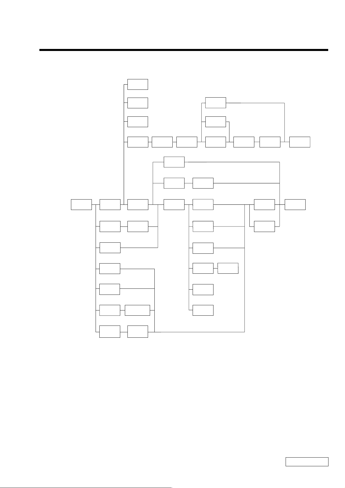
1-1. Flowchart
SPEAKER
P 1-10
SWX-78
BOARD
P 1-10
IFX-159
BOARD
P 1-10
HINGE
COVER
P 1-5 P 1-12 P 1-13
DISPLAY
BASE
P 1-6
HYDROGEN
BEZEL
14 ASSY
NICKEL
BATTERY
P 1-4
INVERTER
UNIT
P 1-13
BRACKET
LCD L (SA)
P 1-13
BRACKET
LCD R (SA)
CHAPTER 1.
REMOVAL
LCD
UNIT
P 1-13 P 1-13
LCD
HARNESS
P 1-13
DISPLAY
ASSY
POWER
OFF
HOOD
KEYBOARD
ASSY
P 1-4
BATTERY
PACK
ESCUSHION
(JOG)
P 1-7
SO-DIMM
P 1-11
HDD
P 1-3
CNX-143
BOARD
P 1-3
MODEM
CARD
P 1-11
KEYBOARD
UNIT
P 1-4
BATTERY
DOOR
P 1-3
COMBINATION
DRIVE
P 1-3
CNX-140
BOARD
P 1-11
DC
FAN
P 1-4 P 1-14
P ALM REST
ASSY
P 1-7 P 1-8 P 1-9 P 1-9
CPU
VIF-17
BOARD
PWS-16
BOARD
P 1-8
HEAT
SINK (AL)
P 1-8
LATCH
DETECTOR
ASSY
P 1-8 P 1-8
SWX-79
BOARD
P 1-10
TOUCH
PAD
P 1-10
LEX-31
BOARD
PC CARD
CONNECTOR
I/O
BRACKET
ASSY
P 1-9
MBX-55
BOARD
• P XX means pages that appears in this manual.
• Remember that hard disk drives are easily damaged by vibration. Always handle with care.
1-1
PCG-GR150/GR150K/GR170/GR170K (AM)
Confidential
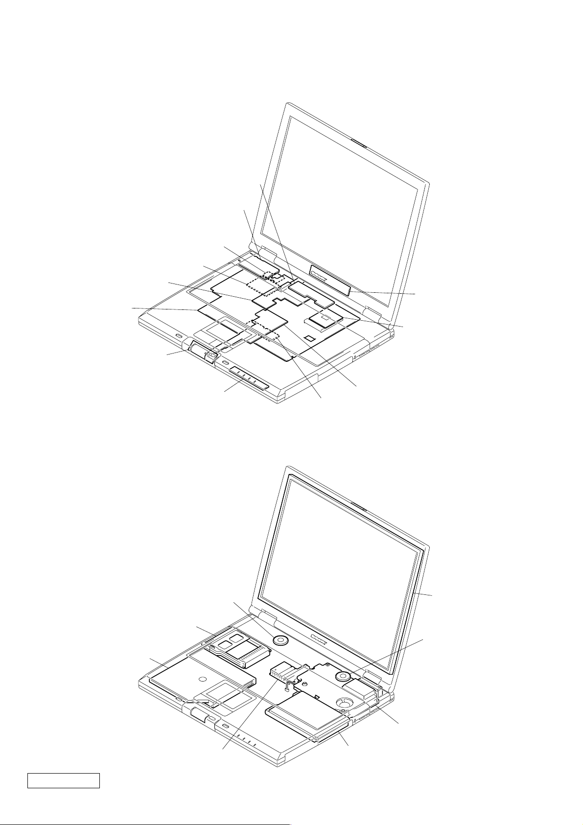
1-2. Main Electrical Parts Location Diagram
SWX-78 Board
IFX-159 Board
CNX-140 Board
Modem Card
VIF-17 Board
MBX-55 Board
SWX-79 Board
Inverter Unit
CPU
PC Card Connector
Combination Drive
LEX-31 Board
Speaker
PWS-16 Board
SO-DIMM
LCD Unit
Speaker
Heat Sink (AL)
Confidential
PCG-GR150/GR150K/GR170/GR170K (AM)
DC Fan
HDD
1-2
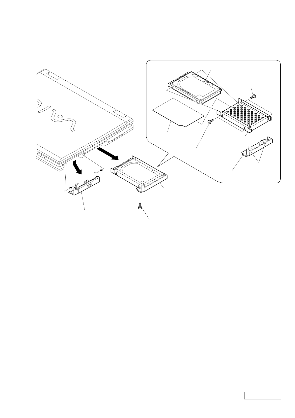
1-3. Removal
2 Battery Door
3 Screw M3 (Black)
3 Screw M3X4
(X2) (Gold)
5 HDD Bracket
HDD Sheet
4 Screw M3X4
(X2) (Gold)
6 HDD
5 HDD Assy
4
1
1 Two Claws
2 HDD Door
1. HDD, Battery Door
1-3
Confidential
PCG-GR150/GR150K/GR170/GR170K (AM)
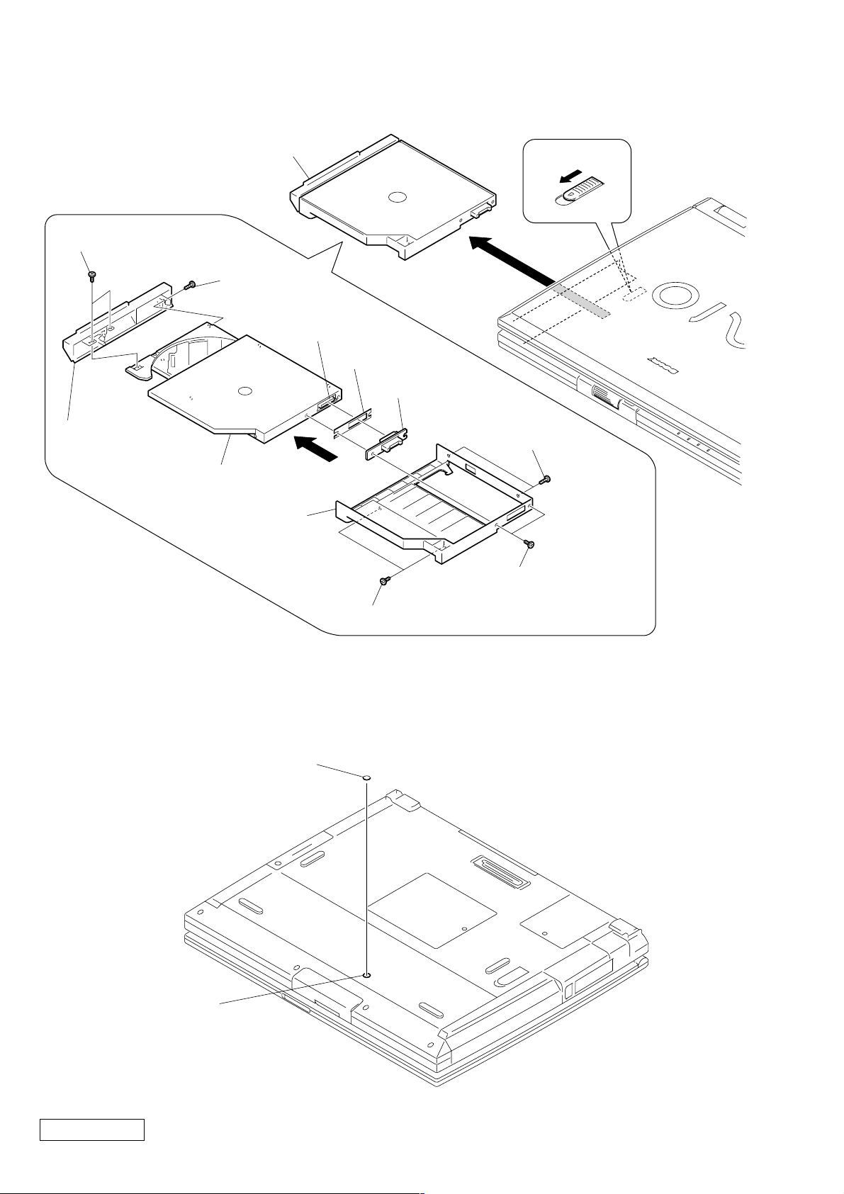
2. Combination Drive, CNX-143 Board
3 DVD-RW Assy
8 Screw
(M1.7X3.5) (X2) (Black)
9 CD Bay Bezel
q; Combination Drive
5 Bay Case
1
2
7 Screw
(M1.7X3.5)
(Black)
CN7501
Bay Board Sheet
6 CNX-143
Board
2 Screw M2
(X2) (Silver)
4
1 Special Head Screw
(M2X4) (X2) (Black)
3 Screw M2 (X2) (Silver)
Note : If the DVD-RW Assy cannot be removed, there is a case that the portion (A) on the rear
of the main unit is secured by screw. Remove the screw blind seal (Cap Bay) and check it.
Cap Bay
A
Confidential
PCG-GR150/GR150K/GR170/GR170K (AM)
1-4
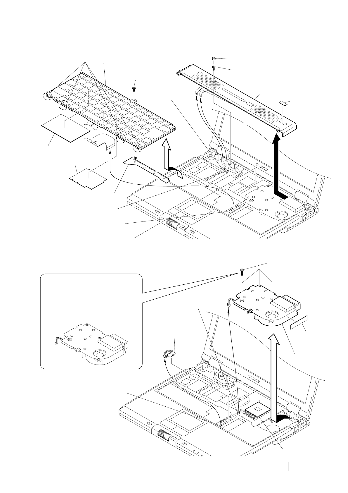
3. Hood Key Board Assy, Keyboard Unit
A
B
C
MBX-55 Board
CN101
MBX-55 Board
CN2610
CPU (
∗1)
1 0 Numbr P3 Kind
Screw (M2) (X3)
(Black)
4 DC Fan
Fan Case
Sheet
6 Nickel Hydrogen
Battery
2
3
5
A
B
C
Note : In both cases of removing
and installing the screws,
follow the order of screwing
starting from A, B and C
in this order.
Four Claws
Plate Keyboard
Plate Keyboard2
q; Bracket Keyboard
MBX-55 Board CN2001
MBX-55 Board CN1901
qa Keyboard Unit
7 Special Head Screw
(M2X4) (Black)
MBX-55 Board
CN1151
9
8
4
1 Cushion (Hood)
2 Special Head Screw
(M2X4) (Black)
6 Hood Key Board Assy
Label ID (U)
5
3
4. DC Fan, Nickel Hydrogen Battery
∗1 When removing the CPU, refer to
“1-4. Replacing the CPU ”.
1-5
Confidential
PCG-GR150/GR150K/GR170/GR170K (AM)
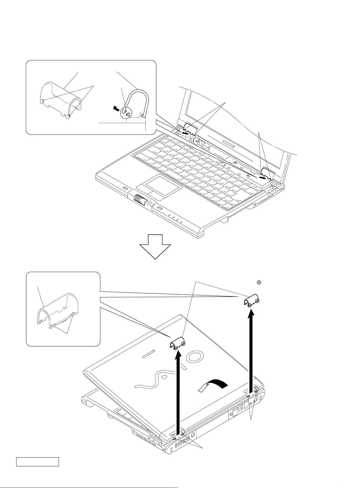
5. Hinge Cover
Hinge Cover
Two Claws
2 Two Claws
1 Two Claws
Hinge Cover
Two Claws
4 Two Hinge Covers
: claw part
3
Two Claws
Confidential
PCG-GR150/GR150K/GR170/GR170K (AM)
Two Claws
1-6
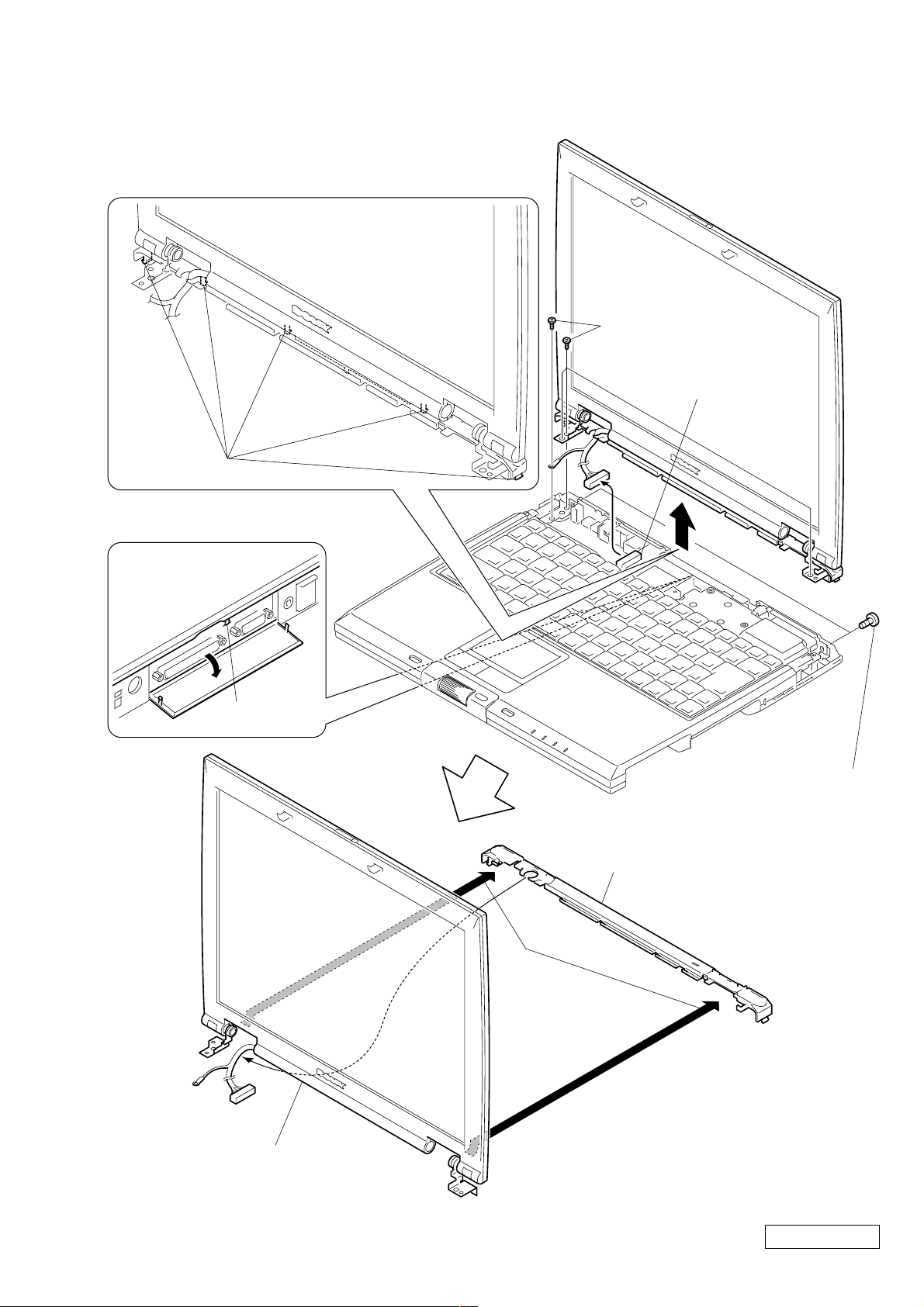
6. Display Base
5 Five Claws
4 Claw
3
1 Screw M3 (X2) (Black)
9 Display Base
Display Assy
8
7
2 Special Head Screw
(M2X6) (X4) (Gold)
VIF-17 Board CN9321
6
1-7
Confidential
PCG-GR150/GR150K/GR170/GR170K (AM)
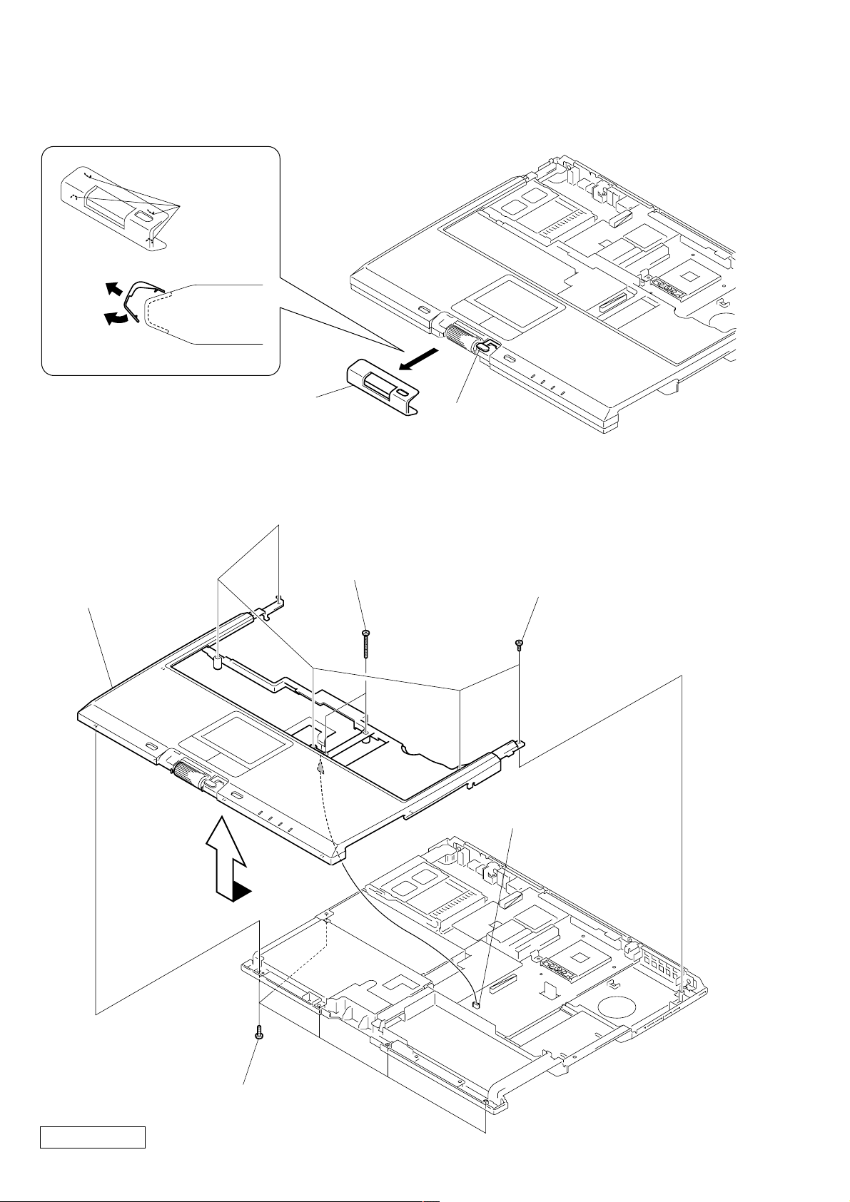
7. Escushion (Jog)
2
1
Four Claws
3 Escushion (Jog)
Note : When removing the Escushion (Jog),
be careful not to damage the Switch (Back).
8. Palm Rest Assy
6 Palm Rest Assy
1
Switch (Back)
4 0 Numbr P3 Kind Screw
(M2X16) (X2) (Black)
3 Special Head Screw
(M2X6) (X5) (Gold)
5
2 Special Head Screw
(M2X4) (X5) (Black)
Confidential
PCG-GR150/GR150K/GR170/GR170K (AM)
MBX-55 Board CN2002
1-8
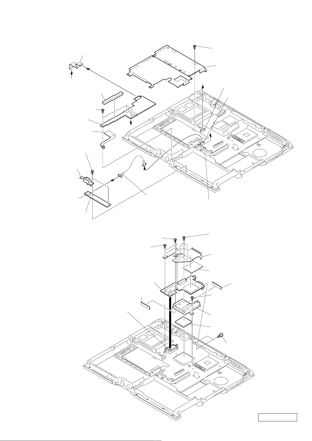
9. Latch Detector Assy, LEX-31 Board, PWS-16 Board
9 Flexible Flat Cable (18p)
8
7
B
Cushion PWS
5 Special Head Screw
(M2X4) (X3) (Black)
qa PWS-16 Board
q; Plate earth
1 Special Head Screw
(M2X4) (X2) (Black)
2 Latch
Detector Assy
PWS-16 Board
CN4001
3
A
6
qs
qd Harness (10p)
qf Special Head Screw
(M2X4) (Black)
qg Bracket Bay Assy
B
MBX-55 Board CN2602
MBX-55 Board CN2003
A
MBX-55 Board CN2601
4 LEX-31 Board
10. Heat Sink (AL) , VIF-17 Board
2 Special Head Screw (M2X6) (Gold)
1 Special Head Screw
(M2X4) (X2) (Black)
7 VIF-17 Board
Filament Tape (W9X30)
MBX-55 Board CN601
6
3 Special Head Screw
(M2X4) (X3) (Black)
4 Plate ATI
Sheet ATI
Filament Tape (W9X30)
8 Special Head Screw
(M2X6) (Gold)
q; Heat Sink (AL)
9 Thermal Sheet AL
5 Screw (Hex) (X2) (Silver)
1-9
Confidential
PCG-GR150/GR150K/GR170/GR170K (AM)
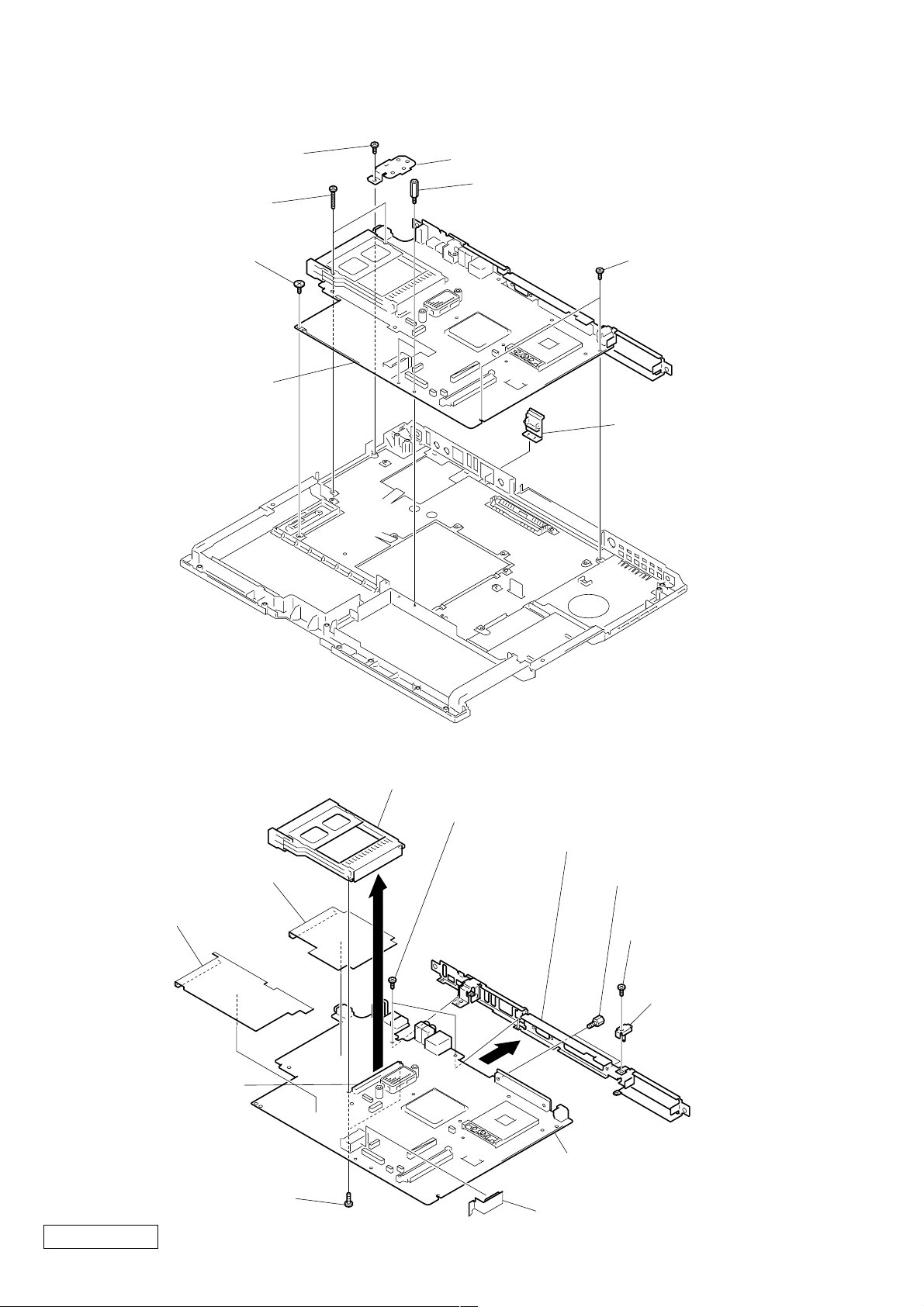
11. MBX-55 Assy
1 Special Head Screw
(M2X4) (Black)
3 0 Numbr P3 Kind Screw
(M2X16) (X2) (Black)
4 Screw (MBX) (Silver)
7 MBX-55 Assy
2 Bracket 1394
5 Spacer (PWS) (X2) (Silver)
6 Special Head Screw
(M2X4) (X2) (Black)
8 Cap Ethernet
12. PC Card Connector, MBX-55 Board, IO Bracket Assy
3 PC Card (Eject, Right) Connector
7 Special Head Screw (M2X4) (X2) (Black)
PC Card Sheet
2
Drive Sheet
8
MBX-55 Board CN1202
1 Special Head Screw
(M2X6) (X2) (Gold)
Confidential
PCG-GR150/GR150K/GR170/GR170K (AM)
1-10
9 IO Bracket Assy
6 Screw (Hex)
(X2) (Silver)
4 Special Head Screw
(M2X4) (Black)
5 Plate (DC)
q; MBX-55 Board
Drive2 Sheet
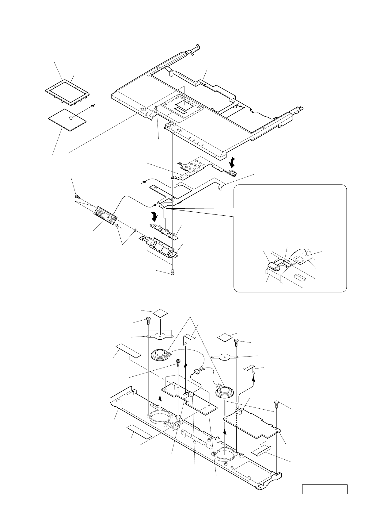
13. SWX-79 Board, Touch Pad
5 Special Head Screw
(M2X4) (X2) (Black)
8 Special Head Screw
(M2X4) (X2) (Black)
q; SWX-79 Board
9 Bracket
(Jog)
3 Button
Holder
7 Flexible PWB
qs Plate (GND)
qd Escushion (TP)
Eight Claws
qf Touch P ad
1 Claw
qg Palm Rest Assy
Jog Ring Sheet
6
4
qa
A
A
2
Flexible
PWB
Palm Rest Assy
Switch (Back)
Note : When assembling, insert the
portion of the Flexible PWB
that is shown in illustration,
in between the Switch (Back)
and the Palm Rest Assy and
align the hole with protrusion
Protrusion
Hole
1 Screw M2X4 (X2) (Black)
9 Screw M2X4
(X3) (Black)
qd Screw M2X4
(X2) (Black)
qf IFX-159 Board
Sheet (MS)
qg Hood Keyboard Assy
qa
q; SWX-78 Board
2 Speaker Holder
4 Speaker Holder
8 Flexible Flat Cable (12p)
qs Flexible Flat Cable (8p)
7
6 Speaker (2.8cm)
5
3 Screw M2X4 (X2) (Black)
Sheet Speaker Holder
Sheet Speaker Holder
SWX-78 Board CN6002
IFX-159 Board CN4502
SWX-78 Board CN6001
Filament Tape
(W12X30)
Filament Tape
(W12X30)
14. Speaker, SWX-78 Board, IFX-159 Board
1-11
PCG-GR150/GR150K/GR170/GR170K (AM)
Confidential
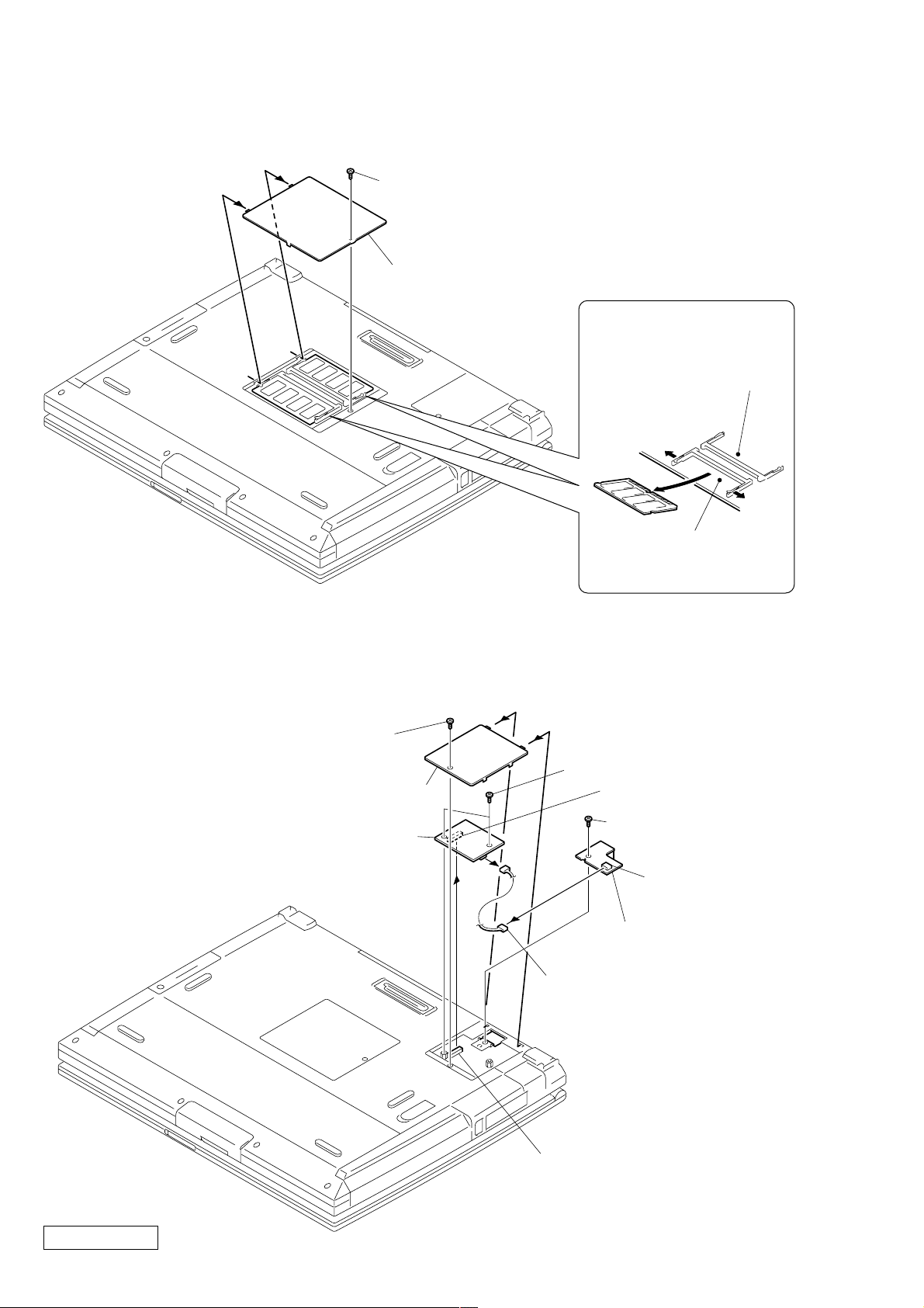
15. SO-DIMM
1 Special Head Screw
(M2X4) (Black)
2 DIMM Door Assy
Removal of SO-DIMM
a → b
PCG-GR170/GR170K
Only
a
b
a
Slot for the standard
memory (Compulsory).
16. Modem Card, CNX-140 Board
1 Special Head Screw
(M2X4) (Black)
2 Modem Door Assy
6 Modem Card
4
5
3 Screw M2 (X2) (Silver)
8
9 Harness (2p)
Modem Card J1
7 Special Head Screw
(M2X4) (Black)
CNX-140 Board
CN5002
q; CNX-140 Board
Confidential
PCG-GR150/GR150K/GR170/GR170K (AM)
MBX-55 Board CN1601
1-12
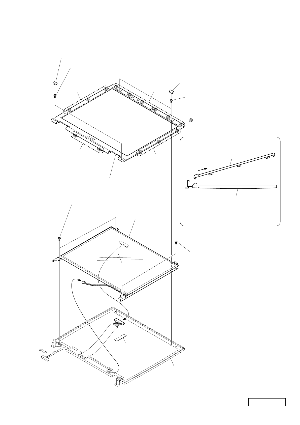
17. LCD Section – Made by SH/HI –
1. Bezel 14 Assy
3 Cover Screw Lower (X2)
4 Special Head Screw
(M2X6) (X2) (Gold)
b
1 Cover Screw Upper (X2)
a
2 Special Head Screw
(M2X4) (X2) (Black)
: claw part
How to release the claw c
c
5 Bezel 14 Assy
6 Special Head Screw
(M2X4) (X2) (Black)
8
b
q; LCD Unit
Bezel 14 Assy
c
Display Assy
Pull the Bezel 14 Assy as shown
to release the claw
c
.
Order of releasing the claws b → a → c
Order of locking the claws c → a → b
7 Special Head Screw
(M2X4) (X2) (Black)
9
Filament Tape
(W19X50)
1-13
Display Assy
Confidential
PCG-GR150/GR150K/GR170/GR170K (AM)
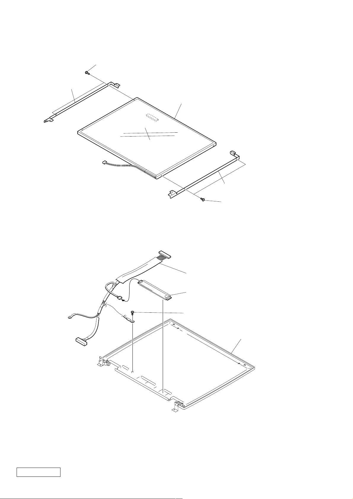
2. LCD Unit, Bracket LCD L (SA), Bracket LCD R (SA)
1 +P M2X3 Lock (X2) (Gold)
2 Bracket LCD L (SA)
5 LCD Unit
4 Bracket LCD R (SA)
3 +P M2X3 Lock (X2) (Gold)
3. Inverter Unit, LCD Harness, Display Assy
1
4 LCD Harness
2 Inverter Unit
3 Special Head Screw
(M2X4) (Black)
Display Assy
Confidential
PCG-GR150/GR150K/GR170/GR170K (AM)
1-14
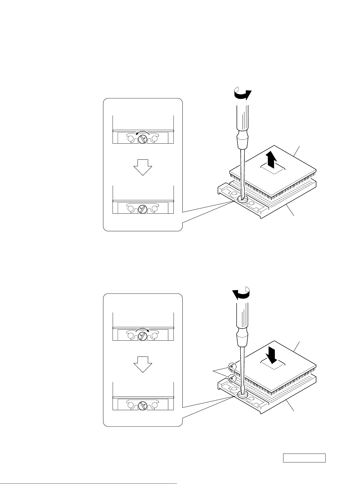
1-4. Replacing the CPU
1. Removing the CPU
1 Insert a flat-blade screwdriver into the notch as shown in the illustration
and rotate it so that the protrusion comes to the lock release position.
2 Pull the CPU gently upward to lift it out of the CPU socket.
1
Lock position
1
CPU
2
Lock release position
2. Installing the CPU
1 Align the triangle reference mark of the CPU with that of the CPU socket and
insert all the pins of the CPU to the corresponding holes of the CPU socket.
2 Insert a flat-blade screwdriver into the notch as shown in the illustration and
rotate it so that the protrusion comes to the lock position.
2
Lock release position
Reference
marks
CPU socket
2
CPU
1
Lock position
NOTE:
Rotate a flat-blade screwdriver to the loc k position securely . If not, the operation of the CPU may become unstable.
CPU socket
Confidential
1-15
PCG-GR150/GR150K/GR170/GR170K (AM)
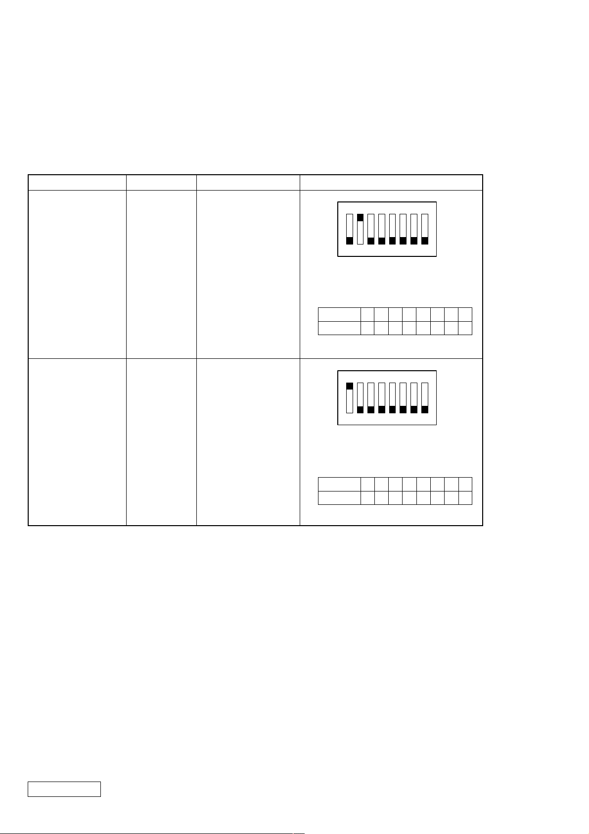
1-5. DIP Switch Setting of the MBX-55 Board
Set the DIP switch on the MBX-55 board (main board) to match with the LCD that is used in this computer,
because several types of LCD are used as shown in the following table and the DIP switch setting differs depending
on the LCD type.
MODEL
GR170/GR170K
GR150/GR150K
Name of LCD
SH
HI
Part No.
A-8066-841-A
1-476-789-11
DIP switch setting
N
O
1234567
The upper position where ON indication is
shown is the ON position . The lower
position is the OFF position.
No.
ON/OFF
12345678
10111111
N
O
1234567
The upper position where ON indication is
shown is the ON position . The lower
position is the OFF position.
8
0 : ON 1: OFF
8
No.
ON/OFF
12345678
01111111
0 : ON 1: OFF
Confidential
PCG-GR150/GR150K/GR170/GR170K (AM)
1-16
(END)

CHAPTER 2.
SELF DIAGNOSTICS
ATTENTION
Please confirm “Self Diagnostics” method which will be informed you with distribution
of “Self Diagnostics” software.
2-1
(END)
Confidential
PCG-GR150/GR150K/GR170/GR170K (AM)
VID
Selector
CPU
VR
Memory Subsystem
PC13 3 SO-DIMM
SO-
DIMM
Socke t 1
Row# 0 , 1
SO-
DIMM
Socke t 2
Row# 2 , 3
CLK GEN
IMIC9870GTD
(CK-Titan)
USB
Port0
USB
Port1
USB
Port2
S MBUS2
2
EEPROM
(Password )
(ROMINFO
3
To Multi Purpose Bay (for future use)
MS
MS
Chipset
To Port Replicator (for future use)
USB
Port4
IFX-159
PC133
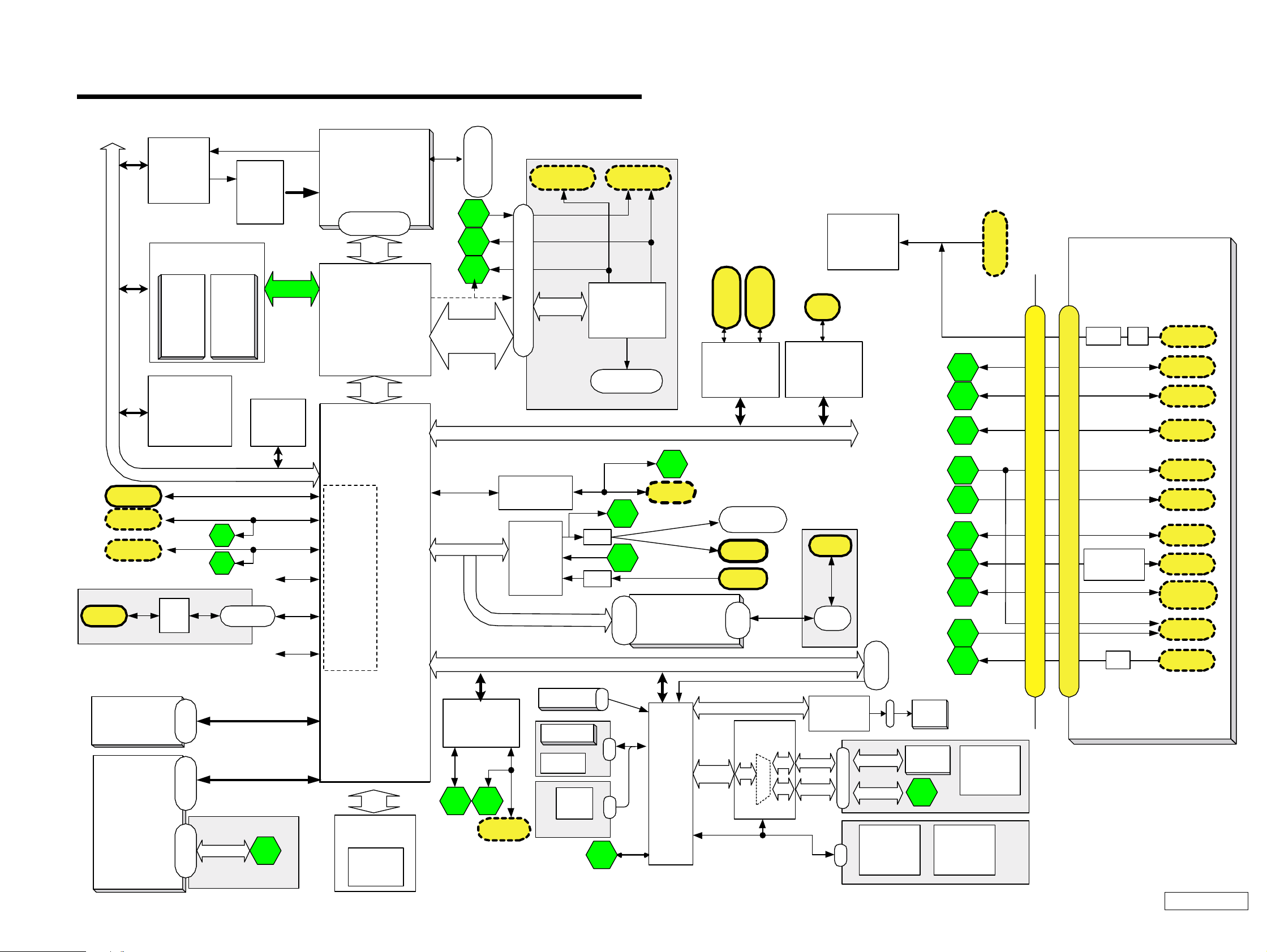
CHAPTER 3.
BLOCK DIAGRAM
PCG-GR Series/PCGA-PRGR1
CPU
Tualatin
(Cache=512kB)
uFCPGA
ctor
Conne
L+
AGT
ITP Connector
10
5
VGA
DSub-15
LINE OUT
TV OUT
A/V OUT
Power
Supply
6
ATI
Mobility M6
Socke t 1
P C Card
Cardbus
Socke t 2
P C Card
Almador-m
GMCH-m
AGP x4
or
DVO_B,C
AGP x4
AGP/DVO-B,C CN
R ICOH
LCD I/F
HL
)
40pin
VIF- 17
PCI
R5C476 II
i.Link
i.LINK
TI
TSB43AA22PDT
ICH3m
4
USB P0
USB P1
USB P2
USB P3
USB P4
USB P5
AC Link
Ether
Kinnerth
Audio
CODEC
AD1881A
10
Amp
11
Amp
MD C
or
Connect
LPC
RJ -45
MDC
AM BIT
Spe aker
(SWX-78)
Headphone
Ext-M
IC
CN
RJ-11
CN
CNX-140
Debug
BLOCK DIAGRAM
Rev. 1.00
USB P1
USB P2
Ether
TVOUT
VGA
Pallarel
Serial
PS/2
LINE
OUT
LINE IN
Port
2
3
4
5
6
7
8
9
10
11
5th/June./'01
DC Jack
100-pin Port Replicator CONNECTOR
PCGA-PRGR1
Port Replicator
CNX-141
FUSE
RS232C
Driver/Receiver
MAX3243
100-pin Port Replicator CONNECTOR
FL
Amp
DC-IN
USB
Port1
USB
Port2
RJ-45
ETHER
S-VIDEO
OUT
VGA
Parallel
DSUB-25
Serial
DSUB-9
PS/2
Mini DIN-6
for KBD
A/V OUT
LINE IN
HDD
MPB
IDE Device
(CD-ROM/CD-RW/DVD)
or
2nd Battery
44pin
MPB
Batt
Header
orConnector
Connect
SMBUS0_2
Primary IDE
Secondary IDE
1
PWS-16
HL
FWH
Flash
BIOS ROM
8 Mbit
Super I/O
LPC47N227
Serial
SMSC
78
Parallel
Dsub-2 5
Int. KBD
Touch Pad
L/R button
Back Button
JogDial
SWX-79
FPC
CN
CN
CN
9
PS/2
EC/KBC/
SPIC
HITACHI
H8S/2149
SMBUS
SMBUS1
I/O Expander
/SMBUS MU X
O2MICRO OZ998
0
ATF Sense
FAN control
ADM1030
SMBUS0_1
SMBUS0_2
CN
CN
CN
LID_SW
POWER_LED
STANDBY_LED
BATT1_LED
BATT2_LED
HDD_LED
FAN
Battery1
1
POWER_SW
MS_LED
NUM_LED
CAPS_LED
SCROLL_LED
SPEAKER
SWX-78LEX-31
Power
Supply
(+3,5VALW/
Batt CHG)
PWS
-16
Confidential
3-23-1
(END)
PCG-GR150/GR150K/GR170/GR170K (AM)
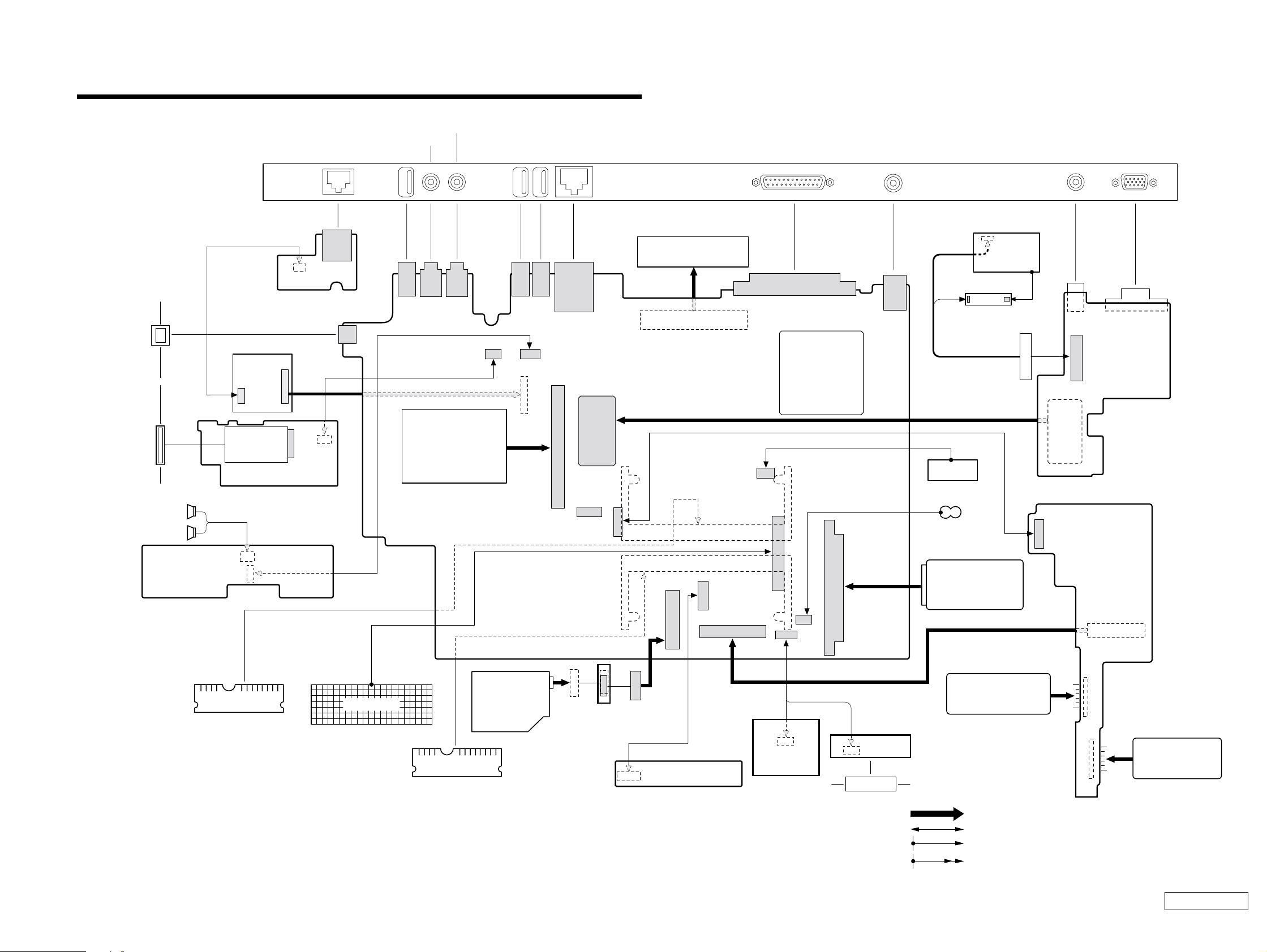
Rear Panel
CHAPTER 4.
FRAME HARNESS DIAGRAM
EXTERNAL MICROPHONE
HEADPHONE
PHONE PRINTER
NETWORK
AV OUT
MONITORDC-INUSB USB USB
IEEE 1394 i.LINK
MEMORY
STICK
SPEAKER
MODEM CARD
Side
CN6002
CN6001
SWX-78 Board
(Side-A)
PCG-GR170/GR170K
: PC133 SO-DIMM 128MB
PCG-GR150/GR150K
: OPTION
HARNESS (2P)
CNX-140 Board
(Side-B)
IFX-159 Board
(Side-A)
41
111
212
RAM
12
CN5002
30
29
J1
2
1
CN4502
CN5001
CN4501
FFC
17
28
FFC
KEY BOARD
CN1301
CN1101
CN1703
CN1141
PC CARD
CONNECTOR
RAM
PC133 SO-DIMM
128MB
CN1701
1
7
2
8
Combination
DRIVE
CN1111
1
2
CN2001
29
1
CN1121
11
12
30
CN1601
2
CN1202
CN1501
78
1
CN601
20
29
1
77 1
154
30
CN3001
49
1
CN7501
17
2
1
50
2
CNX-143 Board
(Side-A)
PCGA-PRGR1
Port Replicator
99
100
MBX-55 Board
(Side-A)
CN2602
18
2
1
2
2
CN2301
60
1
2
59
60
CN7502
HARNESS (10P)
101
CN4001
LEX-31 Board
(Side-A)
CN2901
1
59
21
22
10
CN2003
1
CN2601
1
2
CN101
CN502
CN501
CN1801
12
CN1901
24
143
144
143
144
1
1
1
2
2
CN2002
12 1
J1
TOUCH PAD
CPU
43
21
11
CN2610
12
1
FLEXIBLE PWB
10 1
44
CN2201
2
CN7001
JOG DIAL
CN2801
INVERTER
LCD HARNESS
DC FAN
NICKEL HYDROGEN
BATTERY
HARD DISK
2nd BATTERY PACK
(OPTION)
SWX-79 Board
(Side-B)
From board to connector (direct connection)
Harness (connector at both end)
Harness (soldered at one end)
Connectors soldered on board and appearing on the panel
LCD
FFC
CN9001
1
CN8102
18
J9331
40
2
CN9301
391
CN9321
201
VIF-17 Board
(Side-A)
21
22
CN8101
PWS-16 Board
(Side-B)
CN8121
CN8111
1
2
BATTERY PACK
4-24-1
(END)
Confidential
PCG-GR150/GR150K/GR170/GR170K (AM)

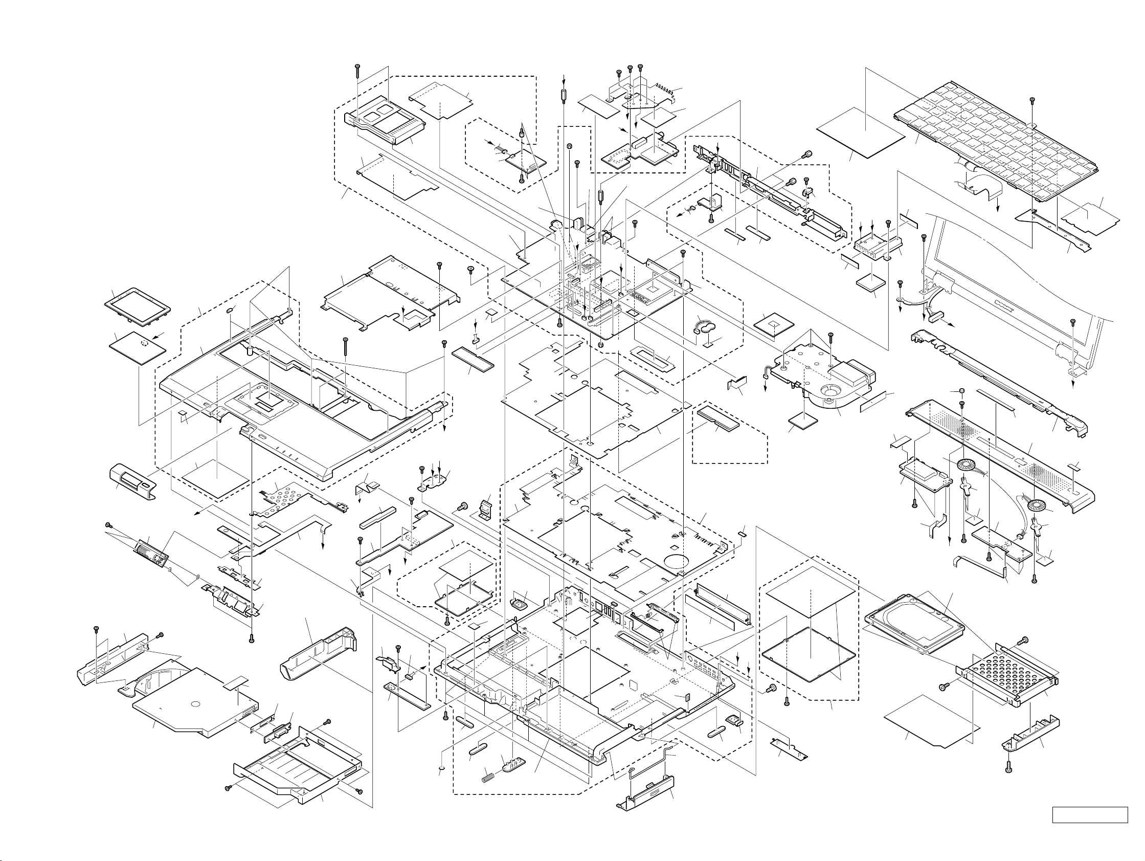
EXPLODED VIEWS AND PARTS LIST
NOTE:
• The mechanical parts with no reference number in the
exploded views are not supplied.
• Items marked “ * ” are not stocked since they are seldom
required for routine service. Some delay should be
anticipated when ordering these items.
• When two or more parts are shown in parallel, use the
part described first as the main part.
CHAPTER 5.
The components identified by mark 0 or
dotted line with mark 0 are critical for safety.
Replace only with part number specified.
Les composants identifiés par une marque
0 sont critiques pour la sécurité.
Ne les remplacer que par une pièce portant
le numéro spécifié.
5-1
Confidential
PCG-GR150/GR150K/GR170/GR170K (AM)

5-1. Main Section
Ref.No. Part No. Description Ref.No. Part No. Description
1 4-653-760-01 ESCUSHION (TP)
2 1-796-166-11 PAD, TOUCH
3 X-4623-630-2 ASSY PALMREST
4 4-653-746-01 ESCUSHION (JOG)
* 5 4-653-796-11 PLATE GND
60 1-476-788-21 KEY BOARD UNIT (US)
61 4-653-766-12 DISPLAY BASE
62 1-796-184-11 HDD (DK23CA-20F-20G)
63 4-653-801-02 SHEET HDD
* 64 4-653-799-02 BRACKET HDD
6 1-761-425-11 PWB, FLEXIBLE
* 7 4-653-795-11 BUTTON HOLDER
* 8 4-653-756-11 BRACKET (JOG)
9 4-657-720-01 JOG RINGSHEET
10 A-8066-782-A COMPLETE PWB SWX-79
11 X-4624-105-1 ASSY CD BAY BEZEL
12 1-796-072-12 COMBO DRIVE (UJDA710)
13 A-8066-778-A COMPLETE PWB CNX-143
14 4-653-767-02 BAY CASE
15 A-8066-840-A MBX-55 ASSY (S)
16 4-654-621-01 SHEET DRIVE
17 1-815-594-11 CONNECTOR, PC CARD (EJECT,RIGHT)
18 4-655-960-01 SHEET PC CARD
19 1-960-827-31 HARNESS (2 PIN)
20 1-761-380-23 CARD, MODEM
21 4-654-439-01 CUSHION (HOOD)
22 8-749-019-77 IC HYM71V16M635HCT6-H
(PC-133 128MB)
23 A-8066-776-A COMPLETE PWB CNX-140
* 24 X-4623-881-1 ASSY BRACKET IO
25 6-700-584-01 (GR150/GR150K)...
IC RH80530GZ866512 (PentiumIII 866MHz)
25 6-700-583-01 (GR170/GR170K)...
IC RH80530GZ001512 (PentiumIII 1000MHz)
* 26 4-654-119-11 PLATE (DC)
27 A-8066-786-A COMPLETE PWB VIF-17
28 X-4623-884-1 ASSY BRACKET BAY
* 29 1-763-715-11 FAN, DC (WITH HEAT SINK)
30 4-653-770-02 INSULATOR HEATSINK BOTTOM
* 31 4-653-727-12 HEATSINK BOTTOM
32 4-653-761-11 CAP ETHERNET
* 33 4-654-285-11 BRACKET 1394
34 1-823-101-11 CABLE, FLEXIBLE FLAT
35 4-654-952-01 CUSHION PWS
36 A-8066-790-A COMPLETE PWB PWS-16
37 X-4623-631-1 ASSY DOOR MODEM
38 4-653-733-02 FOOT WING
39 X-4623-779-1 ASSY LATCH DETECTOR
40 1-961-255-11 HARNESS (10P)
41 A-8066-784-A COMPLETE PWB LEX-31
42 4-653-718-11 FOOT FRONT
43 4-653-731-02 LATCH BAY
44 4-653-745-01 SPRING BAY
45 4-653-793-02 DOOR BATTERY
46 4-653-794-01 DOOR BATTERY SPRING
47 4-653-726-02 DOOR IO
48 4-653-728-01 SPRING DOOR PORT
49 X-4623-628-1 ASSY DOOR DIMM
50 X-4623-629-1 ASSY HOOD KEYBORD
51 4-654-606-01 SHEET (MS)
52 A-8066-788-A COMPLETE PWB IFX-159
53 1-529-878-21 SPEAKER (2.8CM)
54 4-653-753-12 SPEAKER HOLDER
55 1-823-099-11 CABLE, FLEXIBLE FLAT
56 A-8066-780-A COMPLETE PWB SWX-78
57 1-823-100-11 CABLE, FLEXIBLE FLAT
* 58 4-654-388-01 HEAT SINK (AL)
59 4-655-488-01 THERMAL SHEET AL
65 4-653-800-02 DOOR HDD
66 4-655-681-01 SHEET DRIVE2
67 X-4623-627-2 ASSY BOTTOM
68 4-654-379-01 COVER PORT
69 4-654-523-01 LABEL IO
70 4-654-440-12 CUSHION (PALM)
71 1-756-038-11 BATTERY, NICKEL HYDROGEN
72 4-642-711-01 SHEET (BATTERY), ADHESIVE
74 4-654-350-01 SHEET (CPU), THERMAL
75 4-654-953-01 SHEET PORT
76 X-4624-120-1 ASSY BRACKET KEYBOARD
77 4-655-961-01 SHEET FAN CASE
78 X-4624-119-1 ASSY PLATE KEYBOARD
79 4-654-837-01 SHEET BAY BOARD
80 4-656-169-32 (GR150)...LABEL (ID) (U)
80 4-656-169-22 (GR150K)...LABEL (ID) (U)
80 4-656-169-12 (GR170)...LABEL (ID) (U)
80 4-656-169-02 (GR170K)...LABEL ID (U)
81 4-654-380-11 CAP BAY
82 4-657-284-01 ADHESIVE TAPE
84 4-656-070-01 PLATE (PARM)
85 4-656-207-01 PLATE ATI
86 4-656-220-01 SHEET ATI
87 4-653-792-11 BRACKET LOCK
88 4-656-042-02 BLIND SHEET
89 4-656-960-01 PLATE EARTH
90 4-656-906-02 SHEET AL
91 4-656-925-02 SHEET R
92 4-657-577-01 SHEET SPEAKERHOLDER
94 4-657-784-01 PLATE KEYBOARD2
95 4-657-654-01 GASKET USB
96 4-657-655-01 GASKET VGA
97 4-657-657-01 GASKET TV
98 4-657-855-01 LABEL COMBO DRIVE
99 FILAMENT TAPE (W9X30) (∗1)
100 1-779-745-41 JACK, DC
101 1-785-842-11 CONNECTOR, USB (VERTICAL TYPE)
102 1-793-162-11 JACK, SMALL TYPE
103 1-695-514-21 JACK (SMALL TYPE) 1P
104 4-658-513-01 SPACER CE
105 4-654-442-01 ICON SHEET
B1 4-654-387-01 SCREW (MBX)
B2 4-641-726-41 SCREW (M2), SPECIAL HEAD
B3 4-641-726-11 SCREW (M2), SPECIAL HEAD
B4 4-639-112-01 SCREW M2X4
B5 4-645-177-01 SCREW (M1.7X3.5)
B6 4-635-301-01 SCREW M3X4
B7 4-635-966-01 SCREW (HEX)
B8 4-656-703-01 SCREW M2
B10 4-654-386-01 SPACER (PWS)
B11 4-654-385-01 SPACER (VIF)
B12 4-651-989-01 SPACER (MBX)
B13 4-644-899-01 SCREW (M2), 0 NUMBER P3 KIND
B14 4-654-811-01 SCREW M3
B15 7-622-205-05 NUT M2 TYPE2
∗1 Use the FILAMENT TAPE.
Confidential
PCG-GR150/GR150K/GR170/GR170K (AM)
5-2
E
B2
C
B11
101
B15
B3
N
D
102
P
B3
B3
75
27
M
85
86
B3
71
B3
100
23
B
72
95
96
24
25
B7
B7
B3
26
99
B13
78
N
P
59
B2
B2
O
58
99
60
B2
F
B3
94
E
76
B2
C
B13
18
B12
M
Q
17
B3
B2
B1
L
19
20
B8
101
Supplied
with 15
91
16
15
28
1
3
2
K
Supplied
with 3
70
B13
J
B10
90
B15
B3
103
H
I
B2
B5
B3
22
B6
53
B
21
62
B4
B3
B4
54
92
B14
56
57
105
B6
50
G
61
80
53
54
92
B4
64
65
D
66
82
84
89
B3
H
34
35
36
B3
5
4
K
10
6
I
7
9
11
B5
12
B8
8
804
(Refer to Page 5-6.)
B3
98
79
13
B8
14
39
Q
41
B3
B3
J
Supplied
with 37
B3
40
L
O
81
F
B3
B3
33
37
A
42
B14
42
44
32
88
43
31
38
Supplied
with 67
104
30
48
Supplied
with 67
87
GR170/GR170K
Only
46
45
69
67
22
42
47
G
38
74
97
A
B14
B3
68
29
Supplied
with 49
49
77
51
52
B4
55
63
Confidential
PCG-GR150/GR150K/GR170/GR170K (AM)5-3 5-4
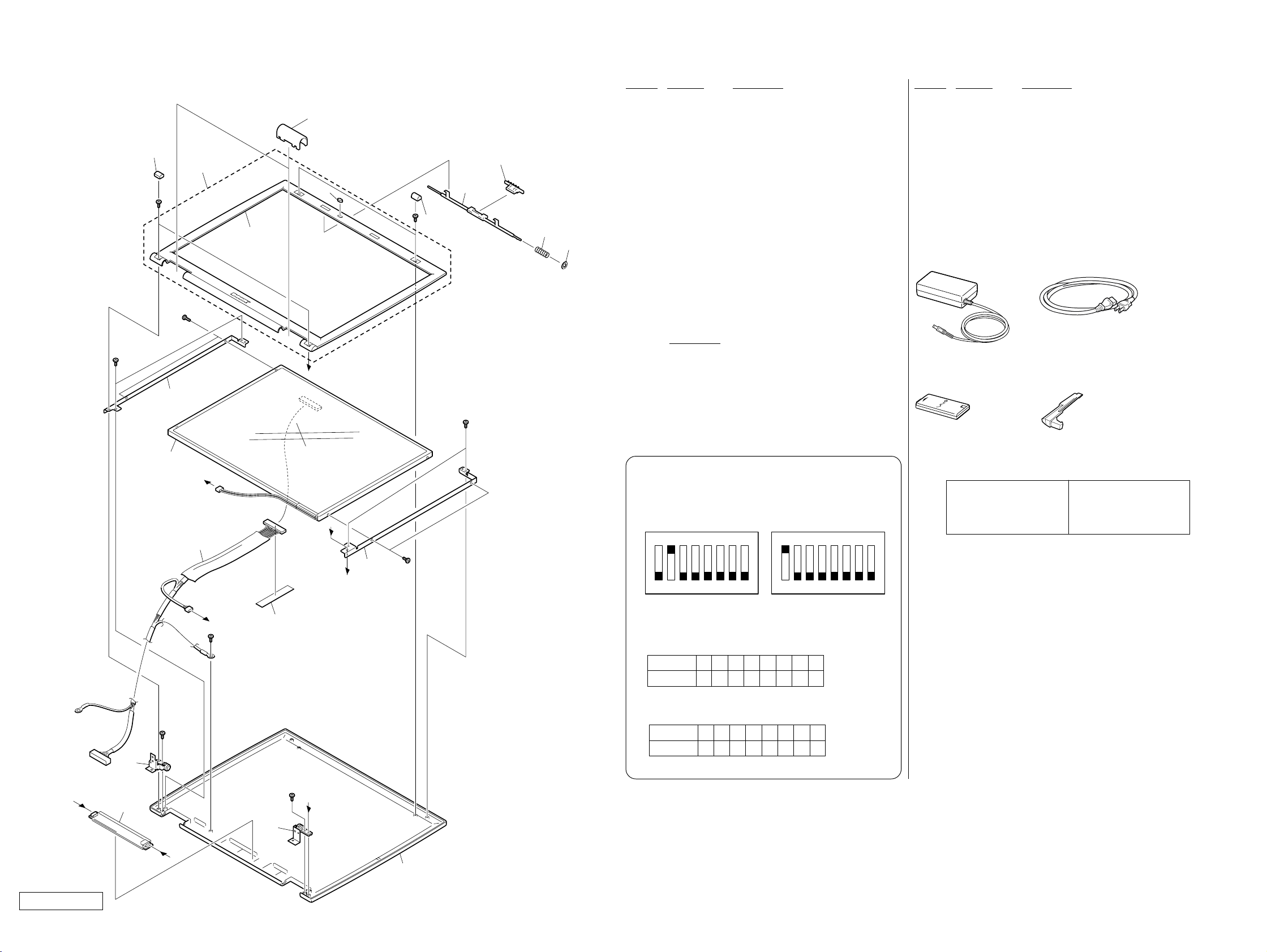
5-2. LCD Section – Made by SH /HI–
403
401
402
404
B2
Supplied
with 402
B3
405
406
407
408
409
Ref.No. Part No. Description Ref.No. Part No. Description
401 4-653-722-01 COVER SCREW LOWER
402 X-4624-046-1 ASSY BEZEL 14 (EXP)
ACCESSORIES
************
403 4-653-754-01 COVER HINGE
404 4-654-794-01 CUSHION LATCH
405 4-653-723-01 COVER SCREW UPPER
0 800 1-476-161-21 ADAPTOR, AC
801 1-756-198-11 BATTERY, LITHIUM ION (L)
0 802 1-757-562-21 CORD, POWER
406 4-653-730-11 HOOK DISPLAY
407 4-653-738-11 LATCH DISPLAY
804 4-653-768-01 WEIGHT SAVER (Refer to page 5-3.)
4-655-646-01 QUICK START,XG
408 4-637-903-01 SPRING LATCH
409 4-656-034-01 WASHER LATCH
* 410 4-653-735-11 BRACKET LCD L (SA)
411 A-8066-841-A (GR170/GR170K)...
ASSY LCD 14SXGA-SH (S)
411 1-476-789-11 (GR150/GR150K)...
LCD UNIT (14.1XGA HI)
* 412 4-653-736-11 BRACKET LCD R (SA)
800
AC Adaptor (1)
802
Power Cord (1)
413 1-961-254-11 (GR170/GR170K)...HARNESS, LCD
413 1-961-256-11 (GR150/GR150K)...HARNESS, LCD
B3
415
410
411
B3
B16
A
413
B3
B
419(∗1)
C
C
D
412
B16
B3
415 X-4623-633-1 HINGE LEFT
416 1-476-735-11 INVERTER UNIT
417 X-4623-634-1 HINGE RIGHT
418 X-4624-047-1 ASSY DISPLAY (EXP)
419 FILAMENT TAPE (W19X50) (
∗1
)
B2 4-641-726-41 SCREW (M2), SPECIAL HEAD
B3 4-641-726-11 SCREW (M2), SPECIAL HEAD
B16 4-642-761-01 +P M2X3 LOCK
∗1 Use the FILAMENT TAPE.
NOTE :
Set the DIP switch on the MBX-55 board (Main board)
to match with the LCD that is used in this computer.
GR170/GR170K GR150/GR150K
N
O
1234567
The upper position where ON indication is shown is the
ON position . The lower position is the OFF position.
GR170/GR170K
No.
ON/OFF
GR150/GR150K
No.
ON/OFF
12345678
10111111
12345678
01111111
8
0 : ON 1: OFF
0 : ON 1: OFF
N
O
1234567
801
Battery Pack (1)
The components identified by
mark 0 or dotted line with mark
0 are critical for safety.
Replace only with part number
specified.
804
Weight Saver (1)
Les composants identifiés par
une marque 0 sont critiques
pour la sécurité.
Ne les remplacer que par une
pièce portant le numéro spécifié.
8
B
416
A
Confidential
PCG-GR150/GR150K/GR170/GR170K (AM)
B3
D
417
418
5-5 5-6
(END)

VAIO® Notebook Quick Start
PCG-GR150/150K PCG-GR170/170K
1

VAIO® Notebook Quick Start
2

Contents
1 Welcome ..........................................................5
Features.......................................................................................... 6
Unpacking Your Notebook..............................................................7
Registering Your Notebook ............................................................9
2 Setting Up Your VAIO® Notebook ...............11
Locating Controls and Ports......................................................... 12
Connecting a Power Source ......................................................... 17
Starting Your Notebook................................................................ 23
Shutting Down Your Notebook..................................................... 24
Using Power Saving Modes.......................................................... 25
3 Adding Memory .............................................27
Precautions and Procedures......................................................... 28
Removing a Memory Module .......................................................30
installing a Memory Module .........................................................31
Viewing the amount of memory ................................................... 32
4 About the Software on Your Notebook .......33
Overview of Software ...................................................................34
Using Your Recovery CDs ............................................................39
5 Troubleshooting............................................43
Troubleshooting the Notebook .....................................................44
Troubleshooting the LCD Screen..................................................48
Troubleshooting the Mouse and Touchpad ..................................49
Troubleshooting Drives, PC Cards, and Peripheral Devices.......... 51
Troubleshooting Software ............................................................53
3

VAIO® Notebook Quick Start
Troubleshooting the Modem.........................................................54
Troubleshooting Audio..................................................................55
Troubleshooting the Printer ..........................................................56
6 Getting Help .................................................. 57
Support Options............................................................................58
VAIO Support Agent......................................................................59
4
 Loading...