

Sony NWZ-A815 User Manual
NW-A805/A806/A808/
NWZ-A815/A816/A818
SERVICE MANUAL
Ver. 1.4 2007.12
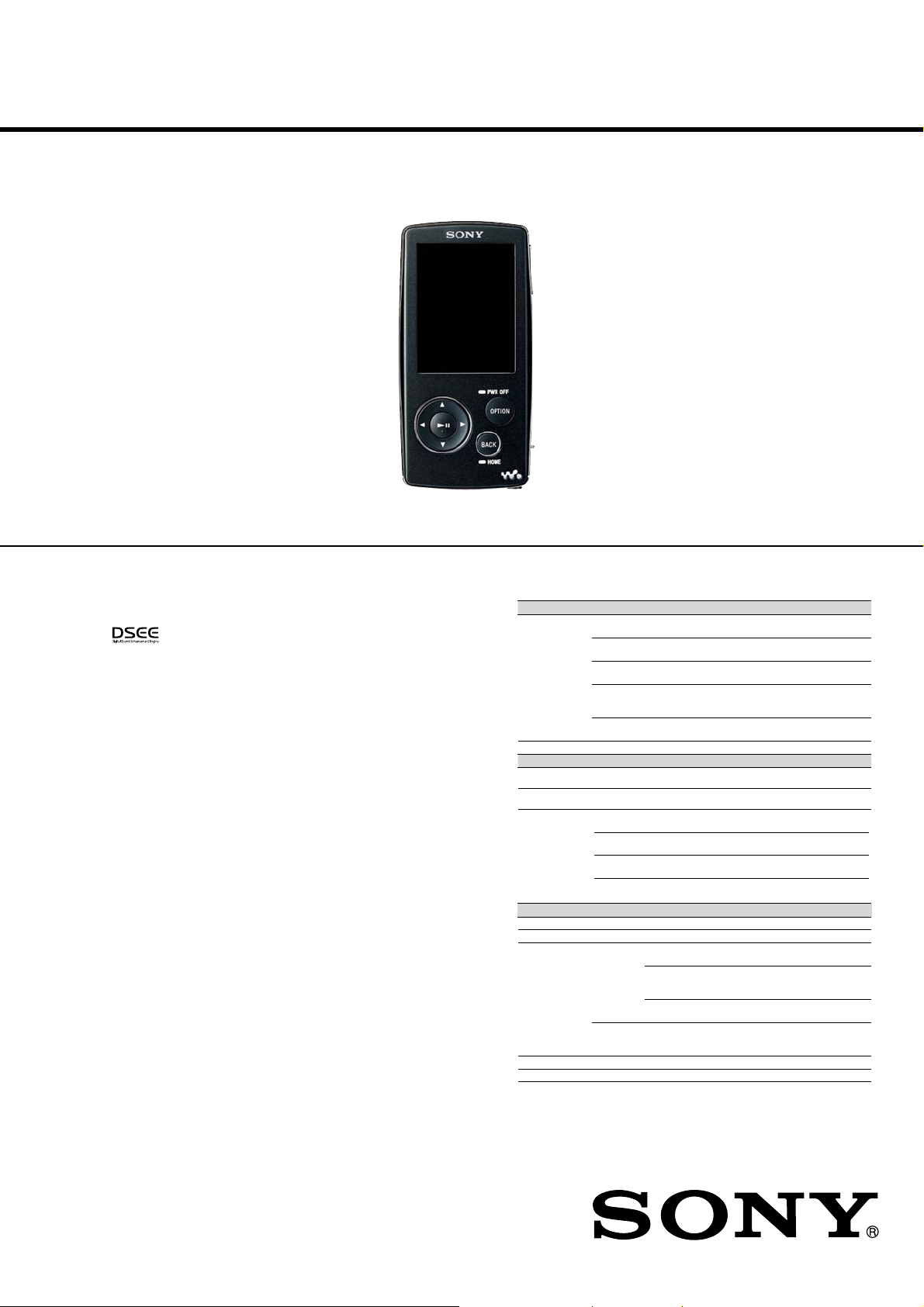
Photo: NW-A808
SonicStage and the SonicStage logo are trademarks or registered trademarks of Sony
•
Corporation.
OpenMG, ATRAC, ATRAC3, ATRAC3plus, ATRAC Advanced Lossless and their logos are
•
trademarks of Sony Corporation.
“WALKMAN”and “WALKMAN” logo are registered trademarks of Sony Corporation.
•
Microsoft, Windows, Windows Vista and Windows Media are trademarks or registered
•
Adobe and Adobe Reader are trademarks or registered trademarks of Adobe Systems
•
MPEG Layer-3 audio coding technology and patents licensed from Fraunhofer IIS and
•
IBM and PC/AT are registered trademarks of International Business Machines Corporation.
•
Macintosh is a trademark of Apple Inc.
•
QuickTime is a trademark or registered trademark of Apple Inc. in the U.S. and/or other
•
Pentium is a trademark or a registered trademark of Intel Corporation.
•
This software is based in part on the work of the Independent JPEG Group.
•
THIS PRODUCT IS LICENSED UNDER THE MPEG-4 VISUAL PATENT PORTFOLIO
•
THIS PRODUCT IS LICENSED UNDER THE AVC PATENT PORTFOLIO LICENSE FOR
•
US and foreign patents licensed from Dolby Laboratories.
•
All other trademarks and registered trademarks are trademarks or registered trademarks of their
•
This product is protected by certain intellectual property rights of Microsoft Corporation.
Use or distribution of such technology outside of this product is prohibited without a license from
from Microsoft or an authorized Microsoft subsidiary.
Program ©2007 Sony Corporation
Documentation ©2007 Sony Corporation
is a trademark of Sony Corporation.
trademarks of Microsoft Corporation in the United States and/or other countries.
Incorporated in the United States and/or other countries.
Thomson.
countries.
LICENSE FOR THE PERSONAL AND NON-COMMERCIAL USE OF A CONSUMER FOR
(i) ENCODING VIDEO IN COMPLIANCE WITH THE MPEG-4 VISUAL STANDARD
(“MPEG-4 VIDEO”) AND/OR
(ii) DECODING MPEG-4 VIDEO THAT WAS ENCODED BY A CONSUMER ENGAGED
IN A PERSONAL AND NON-COMMERCIAL ACTIVITY AND/OR WAS OBTAINED
FROM A VIDEO PROVIDER LICENSED BY MPEG LA TO PROVIDE MPEG-4 VIDEO.
NO LICENSE IS GRANTED OR SHALL BE IMPLIED FOR ANY OTHER USE.
ADDITIONAL INFORMATION INCLUDING THAT RELATING TO PROMOTIONAL,
INTERNAL AND COMMERCIAL USES AND LICENSING MAY BE OBTAINED FROM
FROM MPEG LA, LLC. SEE HTTP://WWW.MPEGLA.COM
THE PERSONAL AND NON-COMMERCIAL USE OF A CONSUMER TO
(i) ENCODE VIDEO IN COMPLIANCE WITH THE AVC STANDARD (“AVC VIDEO”)
AND/OR
(ii) DECODE AVC VIDEO THAT WAS ENCODED BY A CONSUMER ENGAGED IN A
PERSONAL AND
NON-COMMERCIAL ACTIVITY AND/OR WAS OBTAINED FROM A VIDEO PROVIDER
LICENSED TO PROVIDE AVC VIDEO. NO LICENSE IS GRANTED OR SHALL BE
IMPLIED FOR ANY OTHER USE.
ADDITIONAL INFORMATION MAY BE OBTAINED FROM MPEG LA, L.L.C. SEE
HTTP://MPEGLA.COM
TM
respective holders. In this manual,
and ® marks are not specified.
US Model
NWZ-A815/A816/A818
Canadian Model
AEP Model
UK Model
Australian Model
New Zealand Model
Hong Kong Model
Singapore Model
NW-A805/A806/A808/NWZ-A815/A816/A818
E Model
Chinese Model
Tourist Model
NW-A805/A806/A808
SPECIFICATIONS
Supported file format
Music (NW-A805/A806/A808)
Codec MP3 Bit rate: 32 to 320 kbps, variable bit rate-compliant (VBR)
WMA*
ATRAC Bit rate: 48 to 352 kbps (66*
ATRAC
Advanced
Lossless*
AAC*
The number of songsMax. 65,535
Music (NWZ-A815/A816/A818)
File format MP3(MPEG1 Layer3) file format, ASF file format, MP4 file format, Wave-Riff file
File extension File extension MP3 (.mp3), WMA (.wma), AAC-LC*
Codec MP3 Bit rate: 32 to 320 kbps (Supports variable bit rate (VBR))
Video
Video
File format MP4 file format, “Memory Stick” video format
File extension .mp4, .m4v
Codec MP3 MPEG-4
File size Max. 2 GB
The number of files Max. 1,000
format
(.wav)
WMA*2Bit rate: 32 to 192 kbps (Supports variable bit rate (VBR))
AAC-LC*
Linear PCM Bit rate: 1,411 kbps
Audio AAC-LC Channel number: Max. 2 channels
Sampling frequency*
2
Bit rate: 32 to 192 kbps, variable bit rate-compliant (VBR)
Sampling frequency*
Sampling frequency*
Bit rate: 64 to 352 kbps (132 kbps for ATRAC3 base layer)
Sampling frequency*
4
2
Bit rate: 16 to 320 kbps, variable bit rate-compliant (VBR)*
Sampling frequency*1: 8, 11.025, 12, 16, 22.05, 24, 32, 44.1, 48 kHz
Sampling frequency*
Sampling frequency*
2
Bit rate: 16 to 320 kbps (Supports variable bit rate (VBR))*
Sampling frequency*2: 8, 11.025, 12, 16, 22.05, 24, 32, 44.1, 48 kHz
Sampling frequency*
(NW-A805/A806/A808)
AVC
(H.264/AVC)
Frame rate: Max. 30 fps
Resolution: Max. QVGA (320 × 240)
1
: 32, 44.1, 48 kHz
1
: 44.1 kHz
3
, 105*3, 132 kbps for ATRAC3)
1
: 44.1 kHz
1
: 44.1 kHz
5
1
(.mp4, .m4a, .3gp), Linear PCM
2
: 32, 44.1, 48 kHz
2
: 44.1 kHz
2
: 44.1 kHz
Profile: Simple Profile
Bit rate: Max. 2,500 kbps
Profile: Baseline Profile
Level: 1.2, 1.3
Bit rate: Max. 768 kbps
Sampling frequency: 24, 32, 44.1, 48 kHz
Bit rate: Max. 288 kbps per 1 channel
3
– Continued on next page –
DIGITAL MEDIA PLAYER
9-887-631-05
2007L05-1
© 2007.12
Sony Corporation
Audio Business Group
Published by Sony Techno Create Corporation
NW-A805/A806/A808/NWZ-A815/A816/A818
Ver. 1.2
6
Photo*
File format Compatible with DCF 2.0/Exif 2.21file format
File extension .jpg
Codec JPEG (Baseline)
The number of files Max. 10,000
*1 Sampling frequency may not correspond to all encoders.
2
Copyright protected WMA/AAC/AAC-LC files cannot be played back.
*
3
You cannot record songs on CDs in the ATRAC3 66/105 kbps format using SonicStage.
*
4
The bit rate description of ATRAC Advanced Lossless shows the bit rate for the contents
*
which enables fast transfer to ATRAC compatible devices or media.
5
Non-standard bit rates or non-guaranteed bit rates are included depending on the
*
sampling frequency.
6
Some video files cannot be played back, depending on their file formats.
*
Number of pixels: Max. 4,000 × 4,000 pixels (16,000,000 pixels)
Maximum recordable number of songs and time (Approx.)
The approximate times are based on the case in which you transfer or record only 4
minutes songs (not including videos and photos) in the ATRAC*
Other playable audio file format song numbers and times may differ from ATRAC or MP3
format.
1
Except ATRAC Advanced Lossless. Compression rate of ATRAC Advanced Lossless
*
varies depending on songs.
For example, one CD (containing 15 4-minute songs) is approximately 200 to 500 MB.
Bit rate Songs Time Songs Time
48 kbps 1,300 86 hr. 40 min. 2,700 180 hr. 00 min.
64 kbps 980 65 hr. 20 min. 2,000 133 hr. 20 min.
128 kbps 495 33 hr. 00 min. 1,000 66 hr. 40 min.
256 kbps 250 16 hr. 40 min. 515 34 hr. 20 min.
320 kbps 200 13 hr. 20 min. 410 27 hr. 20 min.
Bit rate Songs Time
48 kbps 5,500 366 hr. 40 min.
64 kbps 4,100 273 hr. 20 min.
128 kbps 2,050 136 hr. 40 min.
256 kbps 1,050 70 hr. 00 min.
320 kbps 840 56 hr. 00 min.
Bit rate Songs Time Songs Time
48 kbps 1,150 76 hr. 40 min. 2,450 163 hr. 20 min.
64 kbps 885 59 hr. 00 min. 1,850 123 hr. 20 min.
128 kbps 440 29 hr. 20 min. 925 61 hr. 40 min.
256 kbps 220 14 hr. 40 min. 460 30 hr. 40 min.
320 kbps 175 11 hr. 40 min. 370 24 hr. 40 min.
Bit rate Songs Time
48 kbps 5,050 336 hr. 40 min.
64 kbps 3,750 250 hr. 00 min.
128 kbps 1,850 123 hr. 20 min.
256 kbps 945 63 hr. 00 min.
320 kbps 840 56 hr. 00 min.
NW-A805 NW-A806
NW-A808
NWZ-A815 NWZ-A816
NWZ-A818
1
or the MP3 format.
Maximum recordable time of videos (Approx.)
The approximate recordable times is estimated in the case where only videos are
transferred. The time may differ, depending on the conditions under which the player is
used.
Bit rate Time Time Time
384 kbps 7 hr. 40 min. 15 hr. 40 min. 32 hr. 40 min.
768 kbps 4 hr. 20 min. 9 hr. 20 min. 19 hr. 00 min.
Bit rate Time Time Time
Video Format: 384 kbps
Audio Format: 128 kbps
Video Format: 768 kbps
Audio Format: 128 kbps
NW-A805 NW-A806 NW-A808
NWZ-A815 NWZ-A816 NWZ-A818
7 hr. 10 min. 15 hr. 00 min. 30 hr. 40 min.
4 hr. 00 min. 8 hr. 30 min. 17 hr. 30 min.
Maximum recordable number of photos that can be transferred (Approx.)
Max. 10,000
Recordable number of photos may be less depending on file sizes.
Capacity (User available capacity)*
NW-A805: 2 GB (Approx. 1.81 GB = 1,948,622,848 bytes)
NW-A806: 4 GB (Approx. 3.73 GB = 4,008,198,144 bytes)
NW-A808: 8 GB (Approx. 7.56 GB = 8,127,348,736 bytes)
NWZ-A815: 2 GB (Approx. 1.71 GB = 1,840,775,168 bytes)
NWZ-A816: 4 GB (Approx. 3.57 GB = 3,840,638,976 bytes)
NWZ-A818: 8 GB (Approx. 7.30 GB = 7,840,956,416 bytes)
1
Available storage capacity of the player may vary.
*
A portion of the memory is used for data management functions.
Output (headphones)
•
Output
5 mW + 5 mW (16 Ω)
•
Frequency response
20 to 20,000 Hz (when playing data file, single signal measurement)
1
Interface
Headphone: Stereo mini-jack
WM-PORT (multiple connecting terminal): 22 pins
Hi-Speed USB (USB 2.0 compliant)
Operating temperature
5°C to 35°C (41°F to 95°F)
Power source
•
Built-in rechargeable lithium-ion battery
•
USB power (from a computer via the supplied USB cable)
Charging time
USB-based charging
Approx.3 hours (full charge), Approx.1.5 hours (approx. 80%)
Battery life (continuous playback)
The time below is approximated when “New Song Pop Up”, “Clear Stereo”, “DSEE” and
and “Dynamic Normalizer” are set to “Off,” “Display Time” is set to other than “Always
On”, and screensaver, “Equalizer” and “VPT” are set to “None.”
Furthermore, for videos, the time is approximated when the brightness of the screen is set
to “3.”
The time below may differ depending on ambient temperature or the status of use.
Music
Playback at ATRAC 132 kbps Approximately 30 hours
Playback at ATRAC 128 kbps Approximately 27 hours
Playback at ATRAC 48 kbps Approximately 28 hours
Playback at ATRAC Advanced
Lossless 64 kbps
Playback at MP3 128 kbps Approximately 33 hours
Playback at WMA 128 kbps Approximately 33 hours
Playback at AAC 128 kbps Approximately 32 hours
Video
Playback at MPEG-4 384 kbps Approximately 8 hours
Playback at MPEG-4 768 kbps Approximately 7 hours
Playback at AVC 384 kbps Approximately 6.5 hours
Playback at AVC 768 kbps Approximately 6.5 hours
Music
Playback at MP3 128 kbps Approximately 33 hours
Playback at WMA 128 kbps Approximately 33 hours
Playback at AAC-LC 128 kbps Approximately 32 hours
Playback at Linear PCM 1,411 kbps Approximately 35 hours
Video
Playback at MPEG-4 768 kbps Approximately 7 hours
Playback at MPEG-4 384 kbps Approximately 8 hours
Playback at AVC 768 kbps Approximately 6.5 hours
Playback at AVC 384 kbps Approximately 6.5 hours
NW-A805/A806/A808
Approximately 27 hours
NWZ-A815/A816/A818
Display
2.0-inch, low-temperature poly-silicon TFT color display with white LED-backlight,
QVGA (240 × 320 dots), 0.1275 mm dot pitch, 262,144 colors
Dimensions (w/h/d, projecting parts not included)
43.8 × 88.0 × 9.1 (Thinnest part 8.3) mm (1 3/4 × 3 1/2 × 3/8 (Thinnest part 11/32) inches)
Dimension (w/h/d)
44.5 × 88.0 × 9.6 mm (1 13/16 × 3 1/2 × 13/32 inches)
Mass
Approx. 53 g (Approx. 1.9 oz)
Supplied Accessories
Headphones (1)
Headphone extension cord (1)
Earbuds (Size S, L) (1)
1
USB cable*
Attachment (1)
Use when connecting the player to the optional cradle, etc.
CD-ROM*
− SonicStage software
− Image Converter software*
− Operation Guide (PDF file)
CD-ROM*
− MP3 Coversion Tool
(1)
2
(1) (NW-A805/A806/A808)
3
4
(1) (NWZ-A815/A816/A818)
− Windows Media Player 11
− Operation Guide (PDF file)
Quick Start Guide (1)
1
Do not use any USB cable other than the supplied USB cable or the specified
*
optional dedicated cables.
2
Do not attempt to play this CD-ROM in an audio CD player.
*
3
Use this player together with the supplied Image Converter software (version
*
3.0 or later). This software is referred as Image Converter in this manual.
4
Depending on the country/region in which you have purchased the player,
*
the supplied software may be different.
Design and specifications are subject to change without notice.
2

NW-A805/A806/A808/NWZ-A815/A816/A818
MinimumSystem Requirements (for the player)
•
Computer
IBM PC/AT or compatible computer preinstalled with the following Windows operating
systems:
Windows 2000 Professional (Service Pack 4 or later)/Windows XP Home Edition (Service
Pack 2 or later)/Windows XP Professional (Service Pack 2 or later)/Windows XP Media
Center Edition (Service Pack 2 or later)/Windows XP Media Center Edition 2004 (Service
Pack 2 or later)/Windows XP Media Center Edition 2005 (Service Pack 2 or later)/Windows
Vista Home Basic/Windows Vista Home Premium/Windows Vista Business/Windows Vista
Ultimate
Not supported by 64 bit version OS.
Not supported by OSs other than above.
•
CPU: Pentium III 733 MHz or higher (For Windows Vista, Pentium III 800 MHz or higher)
•
RAM: 128 MB or more (For Windows XP, 256 MB or more; for Windows Vista, 512 MB
or more)
•
Hard Disk drive: 240 MB or more of available space (1.5 GB or more is recommended)
More space may be required, depending on the version of the operating system.
Additional space is required for storing music, video and photo data.
•
Display:
− Screen Resolution: 800 × 600 pixels (or higher) (recommended 1,024 × 768 or higher)
− Colors: High Color (16 bit) (or higher) (SonicStage and Image Converter may not operate
properly at color settings at or below 256 colors.)
•
CD-ROM drive (supporting Digital Music CD playback capabilities using WDM)
To create original CDs or to back up audio CDs, a CD-R/RW drive is required.
•
Sound board
•
USB port (Hi-Speed USB is recommended)
•
Internet Explorer 6.0 or later and DirectX version 9.0b or later need to be installed.
•
Internet connection is required to use the CD Data Base (CDDB) or Electronic Music
Distribution (EMD) or to restore the backup data with SonicStage.
•
When converting Windows Media format videos, it is required to have installed the latest
Windows Media Player.
•
When converting QuickTime or M4V format videos, it is required to have installed the latest
QuickTime.
We do not guarantee operation for all computers even if they meet the above System
Requirements.
Not supported by the following environments:
− Personally constructed computers or operating systems
− An environment that is an upgrade of the original manufacturer-installed operating system
− Multi-boot environment
− Multi-monitor environment
− Macintosh
SECTION 1
Ver. 1.2
SERVICING NOTES
TABLE OF CONTENTS
1. SERVICING NOTES ............................................... 3
2. GENERAL ................................................................... 6
3. DISASSEMBLY
3-1. Disassembly Flow ........................................................... 7
3-2. Rear Cabinet Assy ........................................................... 7
3-3. MAIN Board.................................................................... 8
3-4. Holder Connector ............................................................ 8
3-5. NAND Board, SVX Switch Flexible (PWB Assy).......... 9
3-6. Note When Installing The SVX Switch Flexible
(PWB Assy) ..................................................................... 9
3-7. Front Button .................................................................... 10
3-8. SVX LCD Assy (LCD801), Battery Assy....................... 10
3-9. Front Cabinet Assy .......................................................... 11
4. TEST MODE.............................................................. 12
5. DIAGRAMS
5-1. Block Diagram ................................................................ 18
5-2. Printed Wiring Boards – MAIN Section (1/2) –.............. 20
5-3. Printed Wiring Boards – MAIN Section (2/2) –.............. 21
5-4. Schematic Diagram – MAIN Section (1/6) – .................. 22
5-5. Schematic Diagram – MAIN Section (2/6) – .................. 23
5-6. Schematic Diagram – MAIN Section (3/6) – .................. 24
5-7. Schematic Diagram – MAIN Section (4/6) – .................. 25
5-8. Schematic Diagram – MAIN Section (5/6) – .................. 26
5-9. Schematic Diagram – MAIN Section (6/6) – .................. 27
UNLEADED SOLDER
Boards requiring use of unleaded solder are printed with the leadfree mark (LF) indicating the solder contains no lead.
(Caution: Some printed circuit boards may not come printed with
the lead free mark due to their particular size)
: LEAD FREE MARK
Unleaded solder has the following characteristics.
• Unleaded solder melts at a temperature about 40 ˚C higher
than ordinary solder.
Ordinary soldering irons can be used but the iron tip has to be
applied to the solder joint for a slightly longer time.
Soldering irons using a temperature regulator should be set to
about 350 ˚C.
Caution: The printed pattern (copper foil) may peel away if
the heated tip is applied for too long, so be careful!
• Strong viscosity
Unleaded solder is more viscou-s (sticky, less pr one to flow)
than ordinary solder so use caution not to let solder bridges
occur such as on IC pins, etc.
• Usable with ordinary solder
It is best to use only unleaded solder but unleaded solder may
also be added to ordinary solder.
NOTE THE IC301, IC302, IC501, IC503, IC505, IC506,
IC509, IC601, IC602, IC701, IC802, IC803, IC901 AND
IC903 ON THE MAIN BOARD REPLACING
When IC301, IC302, IC501, IC503, IC505, IC506, IC509, IC601,
IC602, IC701, IC802, IC803, IC901 and IC903 on the MAIN board
is damaged, exchange the new MAIN board for the MAIN board
which IC damaged.
6. EXPLODED VIEWS
6-1. Rear Cabinet Section (NW-A805/A806/A808)............... 41
6-2. Rear Cabinet Section (NWZ-A815/A816/A818) ............ 42
6-3. MAIN Board, NAND Board Section
(NW-A805/A806/A808).................................................. 43
6-4. MAIN Board, NAND Board Section
(NWZ-A815/A816/A818) ............................................... 44
6-5. Front Cabinet Section ...................................................... 45
7. ELECTRICAL PARTS LIST................................ 46
Notes on chip component replacement
• Never reuse a disconnected chip component.
• Notice that the minus side of a tantalum capacitor may be
damaged by heat.
Flexible Circuit Board Repairing
• Keep the temperature of the soldering iron around 270 ˚C
during repairing.
• Do not touch the soldering iron on the same conductor of the
circuit board (within 3 times).
• Be careful not to apply force on the conductor when soldering
or unsoldering.
CAUTION
Danger of explosion if battery is incorrectly replaced.
Replace only with the same or equivalent type.
NOTE THE CN601 ON THE MAIN BOARD
REPLACING
When CN601 on the MAIN board is damaged, exchange the new
MAIN board for the MAIN board which connector damaged.
3
NW-A805/A806/A808/NWZ-A815/A816/A818
Ver. 1.3
NOTE THE MAIN BOARD REPLACING
When the MAIN board is replaced, format it according to the
following.
Formatting Memory
You can format the built-in flash memory of the player.
If the memory is formatted, all music, video and photo data, etc., will be
erased.
Be sure to verify the data stored in memory prior to formatting and export
any important data to SonicStage or the hard disk of your computer.
Note
•
This function is only available in the pause mode.
1
Press and hold the BACK/HOME button in the pause mode until the
Home menu appears.
2
Press the f/F/g/G button to select
the 7 button to conrm.
3
Press the f/F/g/G button to select “Common Settings,” and then
press the 7 button to conrm.
The list of Common Settings options appears.
4
Press the f/F/g/G button to select “Format,” and then press the
7 button to conrm.
“All data including songs will be deleted. Proceed?” appears.
Settings
(Format)
5-way button
BACK/HOME
button
(Settings), and then press
5
Press the f/F button to select “Yes,” and then press the 7 button
to conrm.
“All data will be deleted. Proceed?” appears.
6
Press the f/F button to select “Yes,” and then press the 7 button
to conrm.
While the memory is being formatted, an animated display appears.
When initialization finishes, “Memory formatted.” appears.
To cancel the operation
Select “No” in step 5 or 6 and press the 7 button to confirm.
To return to the previous menu
Press the BACK/HOME button.
Note
•
Do not format the built-in flash memory using Windows Explorer.
ABOUT THE BLUE COLOR TYPE OF THE NWZ-A816
US MODEL
Blue color type of NWZ-A816 US model is using parts of violet
color type.
4
NW-A805/A806/A808/NWZ-A815/A816/A818
COLOR VARIATION
Model Destination
CND zz
AEP, UK z zzz
FR z zzz
NW-A805 EE z zzz
E, AUS, JE zz
MX z
CH z zzz
CND zz
AEP, UK z zzz
FR zz
NW-A806 EE zz
E, AUS, JE z zzz
MX zz
CH zz
CND z
AEP, UK zz
FR z
NW-A808 EE z
E, AUS, JE z
MX z
CH z
US zzzz
US (CircuitCity) zz z
NWZ-A815 CND, AEP, UK, NZ, HK, SP, AUS zz
FR zz
EE zz
US zzzzz (Note)
US (BestBuy) zzz
NWZ-A816
NWZ-A818
Note: Blue color type of NWZ-A816 US model is using parts of violet color type.
US (CircuitCity) z
CND, AEP, UK, NZ, HK, SP, AUS z zzzz
FR z zzzz
EE z zzzz
US zz
CND, AEP, UK, NZ, HK, SP, AUS z zzz
FR z
EE z zzz
BLACK VIOLET WHITE PINK SILVER BLUE
COLOR
Ver. 1.4
• Abbreviation
AUS: Australian model
CH : Chinese model
CND : Canadian model
EE : East European model
FR : French model
HK : Hong kong model
JE : Tour ist model
MX : Mexican model
NZ : New Zealand model
SP : Singapore model
5
NW-A805/A806/A808/NWZ-A815/A816/A818
SECTION 2
GENERAL
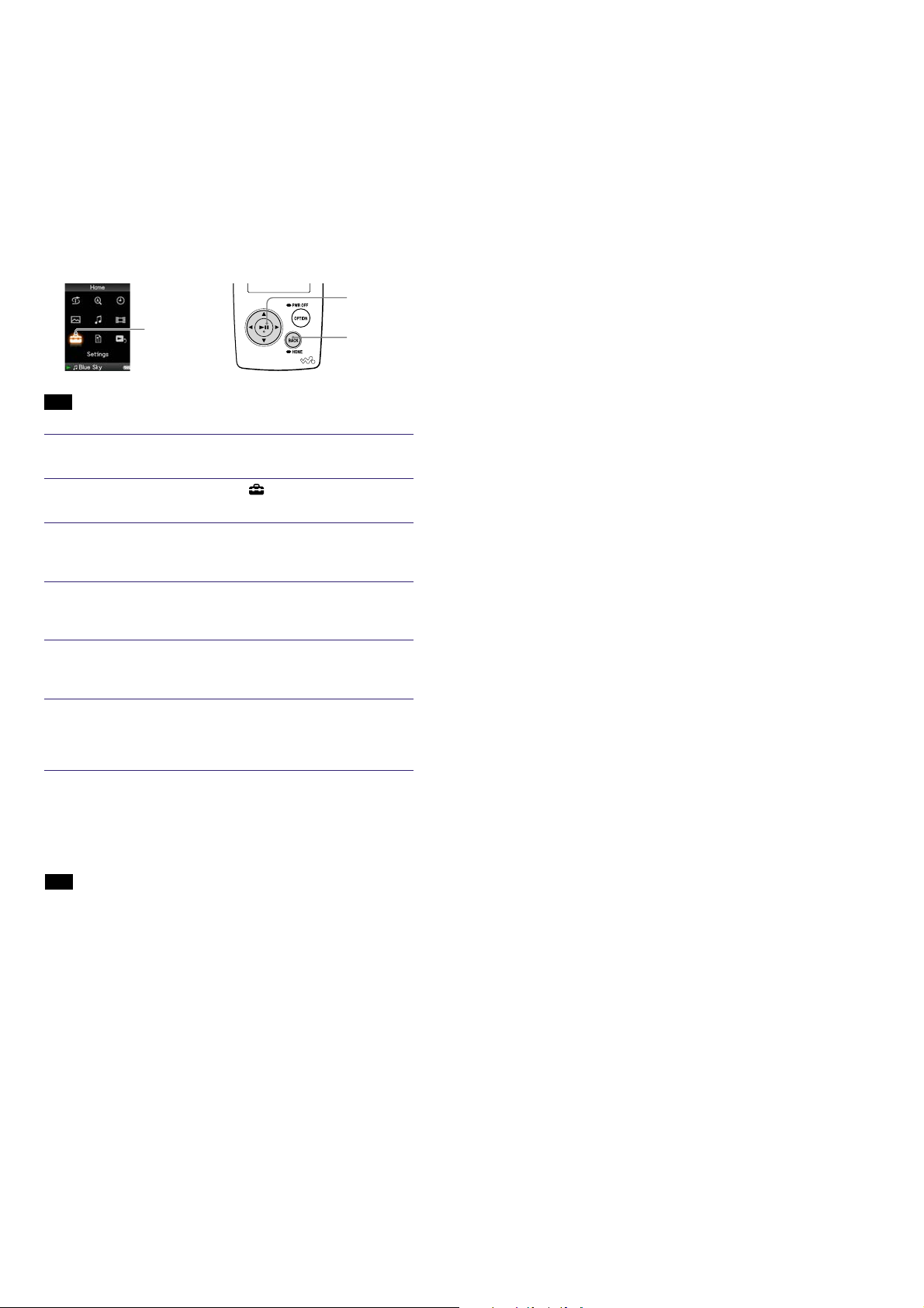
Parts and Controls
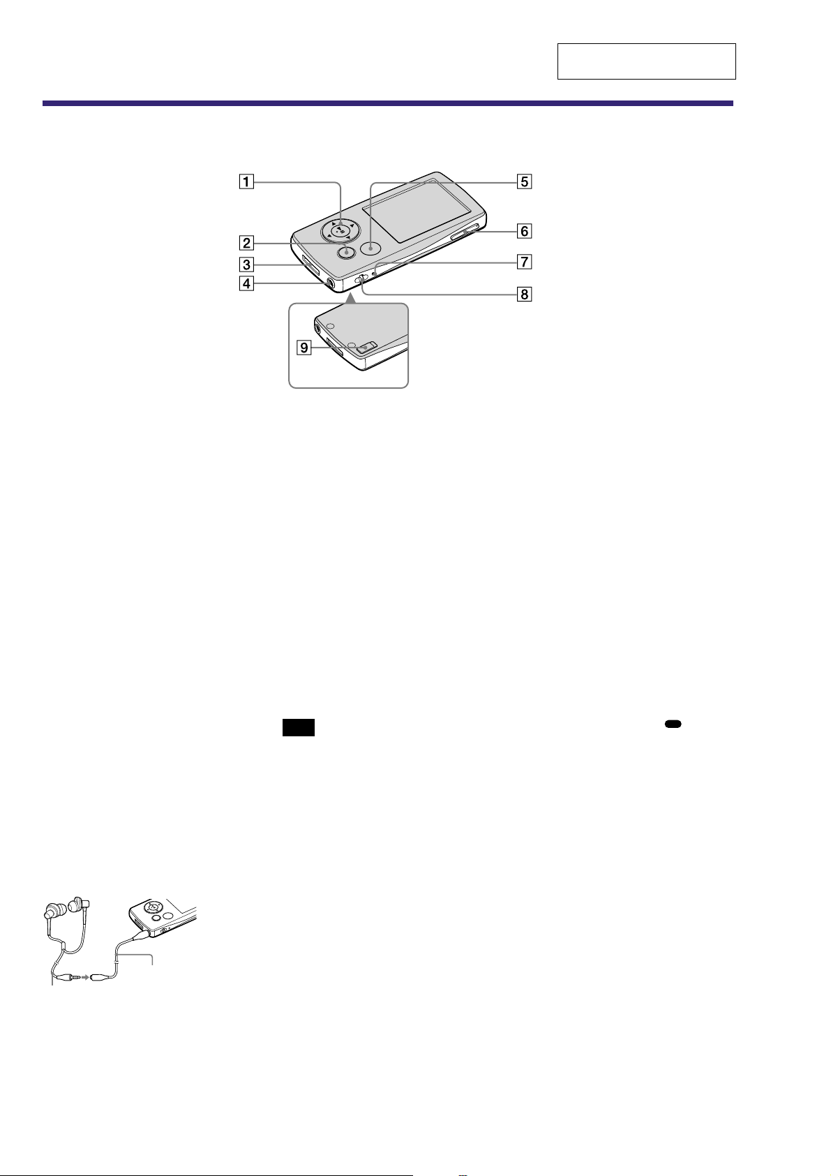
Front
Rear
This section is extracted from
instruction manual.
5-way button*
1
1
Starts playback and enables
navigation of the player’s on-screen
menus.
BACK/HOME button*
2
2
Press to go up one list screen level,
or to return to the previous menu.
Press and hold the BACK/HOME
button to display the Home menu.
WM-PORT jack
3
Use this jack to connect the supplied
USB cable, or optional peripheral
devices, such as supported
accessories for the WM-PORT.
Headphone jack
4
For connecting the headphones or the
headphone extension cord. Insert the
jack pin until it clicks into place. If
the headphones are connected
improperly, the sound from the
headphones may not sound right.
Whenusing the headphone
extension cord
OPTION/PWR OFF button*
5
2
Displays the Option menu.
If you press and hold the OPTION/
PWR OFF button, the screen turns
off and the player enters the standby
mode. If you press any button while
the player is in the standby mode,
the Now Playing screen appears and
the player is ready for operation.
Furthermore, if you leave the player
in the standby mode for about a day,
the player turns completely off
automatically. If you press any button
when the player is turned off, the
start up screen appears first, then the
Now Playing screen appears.
Note
The player consumes the battery very
•
slightly even when it is in the standby
mode. Therefore, the player might
turn completely off in a short time,
depending on the power remaining in
the battery.
1
VOL+ *
6
/-- button
Adjusts the volume.
Strap hole
8
This is used to attach a strap (sold
separately).
HOLD switch
9
You can protect the player against
accidental operation by using the
HOLD switch when carrying it. By
sliding the HOLD switch in the
direction of the arrow, all operation
buttons are disabled. If you slide the
HOLD switch to the opposite
position, the HOLD function is
released.
1
There are tactile dots. Use them to help
*
with button operations.
2
Functions of marked with on the
*
player are activated if you press and hold
the corresponding buttons.
Headphones
6
Headphone
extension cord
RESET button
7
Resets the player when you press the
RESET button with a small pin, etc.

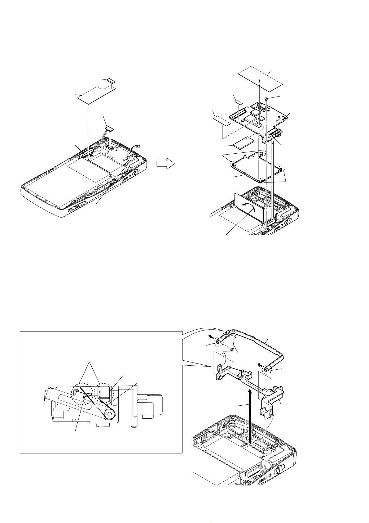
• This set can be disassembled in the order shown below.
3-2. REAR CABINET ASSY
(Page 7)
3-3. MAIN BOARD
(Page 8)
3-4. HOLDER CONNECTOR
(Page 8)
3-5. NAND BOARD,
SVX SWITCH FLEXIBLE (PWB ASSY)
(Page 9)
3-6. NOTE WHEN INSTALLING THE SVX SWITCH FLEXIBLE (PWB ASSY)
(Page 9)
3-7. FRONT BUTTON
(Page 10)
3-8. SVX LCD ASSY (LCD801),
BATTERY ASSY
(Page 10)
3-9. FRONT CABINET ASSY
(Page 11)
SET
3-1. DISASSEMBLY FLOW
NW-A805/A806/A808/NWZ-A815/A816/A818
SECTION 3
DISASSEMBLY
Ver. 1.3
Note: Follow the disassembly procedure in the numerical order given.
3-2. REAR CABINET ASSY
Note 1:Adhesive (rear) cannot re-used.
Please replace to brand-new part
once adhesive (rear) is removed.
Note 2:On installation of hold button,
adjust the position of hold
switch (S602) hold button.
hold switch (S602)
hold button
4
two claws
8
3
claw
(BLACK, SILVER,
VIOLET, BLUE models only)
5
6
adhesive (rear)
hold switch (S602)
2
claw
hold button
6
adhesive (rear)
Note 3:Blue color type of NWZ-A816 US model
is using parts of violet color type.
rear cabinet assy
7
spacer (belt)
3
claw
1
two ornament pins
7
NW-A805/A806/A808/NWZ-A815/A816/A818
3-3. MAIN BOARD
1
cushion (connector)
2
sheet (harness)
4
battery assy connector
(CN901)
3
LCD flexible board
(CN801)
qa
spacer (IC)
qf
spacer (SRAM)
qs
Remove
two solders.
qd
shield case (main)
q;
spacer (PWB)
9
insulating sheet (main)
6
screw (M1.4)
qg
MAIN board
8
connector
(CN601)
qs
Remove
two solders.
5
Unsolder three places of the
HP flexible board,
– rear view –
and turn it up without applying
an excessive force.
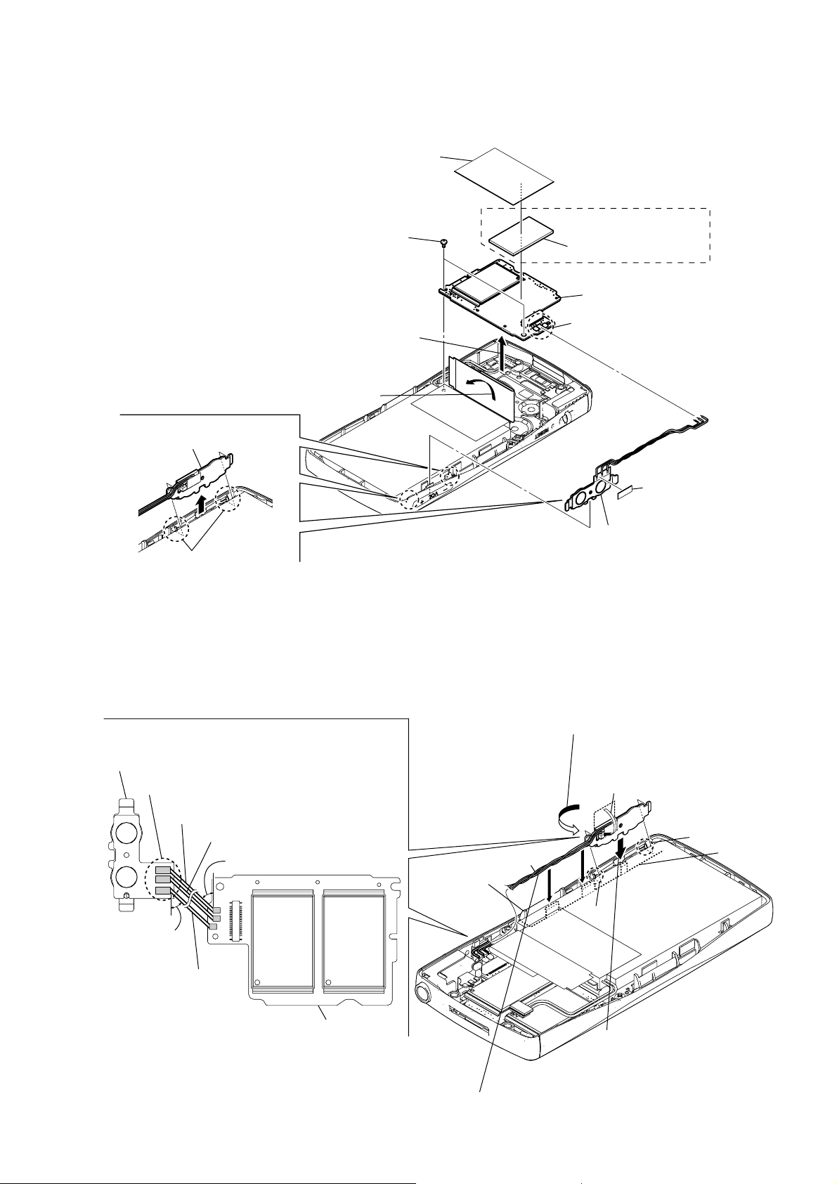
3-4. HOLDER CONNECTOR
NOTE WHEN INSTALLING THE SPRING (DOOR)
Note: Hook the spring (door) on the part A of connector door assy
and the part
B
of holder connector as shown in the figure.
holder connector
spring (door)
A
B
7
Turn up the LCD flexible board.
– rear view –
2
3
6
4
shaft
1
Lift up the
holder connector.
5
spring (door)
connector door assy
4
shaft
7
holder connector
connector door assy
– side view –
– rear view –
8
NW-A805/A806/A808/NWZ-A815/A816/A818
4
Turn up the LCD flexible board.
1
two claws
2
Lift up the
SVX swtch flexible (PWB assy).
5
Lift up the NAND board.
3
two screws (M1.4)
9
sheet (NAND)
qa
NAND board
q;
spacer (NAND)
6
Remove three solders.
8
SVX swtch flexible (PWB assy)
7
insulating sheet
(NW-A805/A806/
NWZ-A815/A816 only)
– rear view –
2
Holding the bent part,
rotate the
SVX swtch flexible (PWB assy)
by 3 or 4 turns in the arrow direction,
and twist to bind the lead wires.
About 45
°
1
Bend the switch flexible board.
4
Push the lead wires completely into a space
between front cabinet assy and LCD holder.
3
Holding the bent part, push in the
SVX swtch flexible (PWB assy)
until it gets stuck by two claws
of the front cabinet assy.
Note: Route the lead wires as shown in the figure,
and solder them at the angle shown in the figure.
Note: The soldering height
should be less than 0.8 mm.
About 45
°
SVX swtch flexible (PWB assy)
NAND board
lead wire (red)
lead wire (gray)
lead wires
front cabinet assy
claw
lead wire (black)
claw
LCD holder
– rear view –
3-5. NAND BOARD, SVX SWITCH FLEXIBLE (PWB ASSY)
Ver. 1.4
3-6. NOTE WHEN INSTALLING THE SVX SWITCH FLEXIBLE (PWB ASSY)
Note: Follow the assembly procedure in the numerical order given.
9
NW-A805/A806/A808/NWZ-A815/A816/A818
n
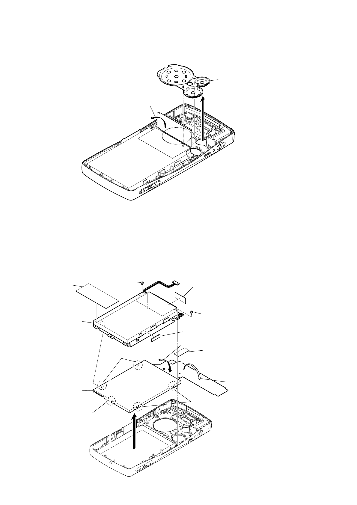
3-7. FRONT BUTTON
1
Turn up the LCD flexible board.
2
front butto
– rear view –
3-8. SVX LCD ASSY (LCD801), BATTERY ASSY
1
q;
spacer (rear)
qa
battery assy
screw (B1.4)
7
two claws
4
adhesive (LCD)
Note: Adhesive (LCD) cannot re-used.
Please replace to brand-new part
ones adhesive (LCD) is removed.
1
screw (B1.4)
9
cushion (BATT)
3
Turn down the LCD flexible board.
6
adhesive (LCD)
Note: Adhesive (LCD) cannot re-used.
Please replace to brand-new part
ones adhesive (LCD) is removed.
10
8
SVX LCD assy
(LCD801)
7
claw
2
– rear view –
7
two claws
5
Open the LCD flexible board.

3-9. FRONT CABINET ASSY
)
NW-A805/A806/A808/NWZ-A815/A816/A818
VOL button
front cabinet assy
Note: The VOL button should be oriented
as shown in the figure when it is installed.
1
VOL button
rear cabinet assy
front cabinet assy back view
2
gasket (rear)
Note: Gasket (rear) cannot re-used.
Please replace to brand-new part
ones gasket (rear) is removed.
Note: NAND gasket cannot re-used.
Please replace to brand-new part
ones NAND gasket is removed.
3
NAND gasket
4
conductive sheet (jack
5
front cabinet assy
– side view –
11
NW-A805/A806/A808/NWZ-A815/A816/A818
SECTION 4
TEST MODE
Note: Information on the test mode must correspond in enough securi-
ty. When the leakage has been revealed by an y chance, the source
of information is specified.
1. SETTING THE TEST MODE
Note: Perform the test mode in the state of 3.6 V or more in the
battery voltage.
Setting method:
1. Turn the power on.
2. Press the [BACK] key for 1.5 seconds or more, the home menu
is displayed.
3. Slide the [HOLD] key to set the hold on.
4. While pressing the [OPTION] key, press the key as follow-
ing order.
v → B → V → b → v → u → v → b → V → B → v → u
5. The set reboots when the [HOLD] key is slided to set the hold
off, and the color bar is displayed in the liquid crystal display .
6. Enter the test mode when the [BACK] key is pressed in the
state of step 5.
Note: The destination setting and sound pressure regulation set-
ting cannot be executed by this test mode.
2. RELEASING THE TEST MODE
1. Display the major item selection screen.
2. Press the v / V key to select the “EXITTEST”, and press the
B key to select the “SURE ?”.
3. Press the u key, turn the power off and release the test mode.
3. CONFIGURATION OF THE TEST MODE
Major item
[ ]
key
Bb
[ ]
Major item switching:
[ ]/ [ ]
v
key
key
V
4-1-1. Power supply voltage check
This mode is used in case power supply voltage in the state where
all power supply lines are starting is checked.
Checking method:
1. Enter the test mode.
2. Press the
v / V key to select the “POWER”, and press the B
key to enter the minor item.
3. Press the
v / V key to select the “VCHK”.
4. Press the u key, all power supply lines are started.
liquid crystal display
POWER VCHK
START
In this state, the power supply voltage of each po wer supply line
can be confirmed by measuring the voltage.
5. Press the [BACK] key, return to minor item selection screen.
4-1-2. Consumption current (audio playback) check
This mode is used in case consumption current (audio playback) is
checked in the state where “1 kHz 0 dBs L-ch/R-ch V OLUME: 15”
audio signal is outputed.
Minor item switching:
[ ]/ [ ]
v
V
key
[ ]
key
u
Automatic
Finish
Result
Start
or
Minor item
[BACK]
4. OPERATION OF THE TEST MODE
4-1. Power
liquid crystal display
MPTAPP MENU
POWER VCHK
AUDIO ACHK
VIDEO DSVCHK
OTHER CHGCHK
SHUTDOWN BATTCHK
EXITTEST
key
Checking method:
1. Enter the test mode.
2. Press the v / V key to select the “POWER”, and press the B
key to enter the minor item.
3. Press the v / V key to select the “ACHK”.
4. Press the u ke y, “1 kHz 0 dBs L-ch/R-ch V OLUE: 15” audio
signal is outputed.
liquid crystal display
POWER ACHK
1kHz 0dBs L/Rch
HPOUT [ VOL: 15 ]
START
5. In this state, each time the [OPTION] key is pressed, LCD back
light on/off switch is performed.
6. Press the [BACK] key, return to minor item selection screen.
12
NW-A805/A806/A808/NWZ-A815/A816/A818
4-1-3. Standby current check
This mode is used in case standby current is checked.
Checking method:
1. Enter the test mode.
2. Press the
v / V key to select the “POWER”, and press the B
key to enter the minor item.
3. Press the
4. Press the
v / V key to select the “DSVCHK”.
u key, enter the state of the deep sleep.
5. Press the [BACK] key, release the state of the deep sleep.
liquid crystal display
POWER DSVCHK
OK
6. Press the [BACK] key, return to minor item selection screen.
4-1-4. Charge current check
This mode is used in case charge current is checked.
4-1-5. Battery voltage check
This mode is used in case battery voltage is checked.
Checking method:
1. Enter the test mode.
2. Press the
v / V key to select the “POWER”, and press the B
key to enter the minor item.
3. Press the
4. Press the
v / V key to select the “BATTCHK”.
u key, the battery voltage is displayed.
When the battery voltage cannot be confirmed, “ERROR” is
displayed.
liquid crystal display
POWER BATTCHK
X.XXXV
X.XXXV: Battery voltage
6. Press the [BACK] key, return to minor item selection screen.
Checking method:
1. Enter the test mode.
2. Press the v / V key to select the “POWER”, and press the B
key to enter the minor item.
3. Press the v / V key to select the “CHGCHK”.
4. Press the u key, the charge setting is displayed.
liquid crystal display
POWER CHGCHK
AC
AC
5. In this state, each time the [OPTION] key is pressed, the port
setting for the charge is changed as shown in the table below.
Port control
Display CHG_XCHGEN CHG_PEN CHG_PEN2
AC L H H
USB500 L H H
USB100 L H L
4-2. Audio
While playing the audio track, it's in a repeat state. If [BACK]
pressed, it’s stopped.
Press the [VOL +] key to switch the HP/LINE.
liquid crystal display
MPTAPP MENU
POWER
AUDIO OUTPUT
VIDEO SN
OTHER F1
SHUTDOWN F2
EXITTEST SEPLR
SEPRL
MAXOUT
NMLZR
SPCHK
key is
6. Press the [BACK] key, return to minor item selection screen.
13
NW-A805/A806/A808/NWZ-A815/A816/A818
4-2-1. Output check
“1 kHz 0 dBs L-ch/R-ch VOLUME: 25” audio signal is outputted.
Checking method:
1. Enter the test mode.
2. Press the
v / V key to select the “AUDIO”, and press the B
key to enter the minor item.
3. Press the
4. Press the
v / V key to select the “OUTPUT”.
u key, “1 kHz 0 dBs L-ch/R-ch VOLUME: 25”
audio signal is outputted.
liquid crystal display
AUDIO OUTPUT
1kHz 0dBs L/Rch
HPOUT [ VOL: 25 ]
START
5. Press the [BACK] key, return to minor item selection screen.
4-2-3. Frequency characteristic 1 check
“20 Hz 0 dBs L-ch/R-ch V OLUME: 25” audio signal is outputted.
Checking method:
1. Enter the test mode.
2. Press the
v / V key to select the “AUDIO”, and press the B
key to enter the minor item.
3. Press the v / V key to select the “F1”.
4. Press the u key, “20 Hz 0 dBs L-ch/R-ch VOLUME: 25”
audio signal is outputted.
liquid crystal display
AUDIO F1
20Hz 0dBs L/Rch
HPOUT [ VOL: 25 ]
START
5. Press the [BACK] key, return to minor item selection screen.
4-2-2. S/N check
“Infinity Zero VOLUME: 30” audio signal is outputted.
Checking method:
1. Enter the test mode.
2. Press the v / V key to select the “AUDIO”, and press the B
key to enter the minor item.
3. Press the v / V key to select the “SN”.
4. Press the u key, “Infinity Zero VOLUME: 30” audio signal
is outputted.
liquid crystal display
AUDIO SN
Infinity Zero
HPOUT [ VOL: 30 ]
START
5. Press the [BACK] key, return to minor item selection screen.
4-2-4. Frequency characteristic 2 check
“20 kHz 0 dBs L-ch/R-ch V OLUME: 25” audio signal is outputted.
Checking method:
1. Enter the test mode.
2. Press the v / V key to select the “AUDIO”, and press the B
key to enter the minor item.
3. Press the v / V key to select the “F2”.
4. Press the u key, “20 kHz 0 dBs L-ch/R-ch VOLUME: 25”
audio signal is outputted.
liquid crystal display
AUDIO F2
20kHz 0dBs L/Rch
HPOUT [ VOL: 25 ]
START
5. Press the [BACK] key, return to minor item selection screen.
14
NW-A805/A806/A808/NWZ-A815/A816/A818
4-2-5. CH separation (L-ch) check
“1 kHz 0 dBs L-ch VOLUME: 25” audio signal is outputted.
Checking method:
1. Enter the test mode.
2. Press the
v / V key to select the “AUDIO”, and press the B
key to enter the minor item.
3. Press the
4. Press the
v / V key to select the “SEPLR”.
u key, “1 kHz 0 dBs L-ch VOLUME: 25” audio
signal is outputted.
liquid crystal display
AUDIO SEPLR
1kHz 0dBs Lch
HPOUT [ VOL: 25 ]
START
5. Press the [BACK] key, return to minor item selection screen.
4-2-6. CH separation (R-ch) check
“1 kHz 0 dBs R-ch VOLUME: 25” audio signal is outputted.
Checking method:
1. Enter the test mode.
2. Press the v / V key to select the “AUDIO”, and press the B
key to enter the minor item.
3. Press the v / V key to select the “SEPRL”.
4. Press the u key, “1 kHz 0 dBs R-ch VOLUME: 25” audio
signal is outputted.
liquid crystal display
AUDIO SEPRL
1kHz 0dBs Rch
HPOUT [ VOL: 25 ]
4-2-7. Maximum output check
“1 kHz 0 dBs L-ch/R-ch VOLUME: 30” (Headphone output when
AVLS operates: “1 kHz 0 dBs L-ch/R-ch VOLUME: 13”) audio signal is outputted.
Checking method:
1. Enter the test mode.
2. Press the
v / V key to select the “AUDIO”, and press the B
key to enter the minor item.
3. Press the v / V key to select the “MAXOUT”.
4. Press the u key, “1 kHz 0 dBs L-ch/R-ch VOLUME: 30”
(Headphone output when AVLS operates: “1 kHz 0 dBs L-ch/
R-ch VOLUME: 13”) audio signal is outputted.
liquid crystal display
AUDIO MAXOUT
1kHz 0dBs L/Rch
HPOUT [ VOL: 30 ]
AVLS OFF
START
5. In this state, each time the [OPTION] key is pressed, AVLS on/
off switch is performed.
6. Press the [BACK] key, return to minor item selection screen.
4-2-8. Normalizer check
“1 kHz –24 dBs L-ch/R-ch VOLUME: 30” audio signal is outputted.
Checking method:
1. Enter the test mode.
2. Press the v / V key to select the “AUDIO”, and press the B
key to enter the minor item.
3. Press the v / V key to select the “NMLZR”.
4. Press the u key, “1 kHz –24 dBs L-ch/R-ch VOLUME: 30”
audio signal is outputted.
liquid crystal display
START
5. Press the [BACK] key, return to minor item selection screen.
AUDIO NMLZR
1kHz –24dBs L/Rch
HPOUT [ VOL: 30 ]
START
5. Press the [BACK] key, return to minor item selection screen.
15
NW-A805/A806/A808/NWZ-A815/A816/A818
4-2-9. Sound pressure regulation level check
“1 kHz 0 dBs L-ch/R-ch VOLUME: 30” audio signal is outputted.
Checking method:
1. Enter the test mode.
2. Press the
v / V key to select the “AUDIO”, and press the B
key to enter the minor item.
3. Press the v / V key to select the “SPCHK”.
4. Press the u key, “1 kHz 0 dBs L-ch/R-ch VOLUME: 30”
audio signal is outputted.
liquid crystal display
AUDIO SPCHK
1kHz 0dBs L/Rch
HPOUT [ VOL: 30 ]
START
5. Press the [BACK] key, return to minor item selection screen.
4-3. Video
4-4. Other
liquid crystal display
MPTAPP MENU
POWER
AUDIO
VIDEO
OTHER CLOCK
SHUTDOWN KEY
EXITTEST FORMAT
DEST
SPSET
FWVER
NCAPCHK
4-4-1. Clock check
The movement of an internal clock is confirmed.
Checking method:
1. Enter the test mode.
2. Press the v / V key to select the “OTHER”, and press the B
key to enter the minor item.
3. Press the v / V key to select the “CLOCK”.
4. Press the u key, date and time are displayed.
liquid crystal display
liquid crystal display
MPTAPP MENU
POWER
AUDIO
VIDEO LCD
OTHER
SHUTDOWN
EXITTEST
4-3-1. LCD display check
Liquid crystal display is checked.
Checking method:
1. Enter the test mode.
2. Press the v / V key to select the “VIDEO”, and press the B
key to select the “LCD”.
3. Press the u key, all black is displayed on the liquid crystal
display.
4. In this state, each time the [OPTION] key is pressed, the screen
display changes in the following order .
OTHER CLOCK
XX, XX XX XXXX
##:##:##.######
START
XX, XX XX XXXX : Date
##:##:##.###### : Time
“START” changes into “OK” if the movement of an internal
clock is confirmed.
5. Press the [BACK] key, return to minor item selection screen.
All black (default) → All red → All g reen → All blue → All
white → Color bar → Maximum drawing size confirmation
Maximum drawing size confirmation:
All blue (All sides are red) is displayed. Whether red in all
sides is seen is confirmed.
4. In this state, each time the [VOL ---] key is pressed, LCD back
light brightness min/max/middle switch is performed.
5. Press the [BACK] key, return to minor item selection screen.
16
 Loading...