

Sony NWS-4 Service manual

NW-S4
SERVICE MANUAL
Ver 1.2 2001.07
SPECIFICATIONS
US Model
9-873-071-13 Sony Corporation
2001G0500-1 Personal Audio Company
C 2001.7 Shinagawa Tec Service Manual Production Group
PORTABLE IC AUDIO PLAYER

NW-S4
TABLE OF CONTENTS
1. SERVICING NOTES.................................................. 3
2. GENERAL ...................................................................... 8
3. DISASSEMBLY
3-1. Disassembly Flow .............................................................. 9
3-2. Lower Case Assy................................................................ 9
3-3. Jack Flexible Module,
Jack (Small Type) (Water Proof) (J301).......................... 10
3-4. MAIN Board .................................................................... 10
3-5. SUB Board ....................................................................... 11
4. DIAGRAMS
4-1. Block Diagram ................................................................. 13
4-2. Note for Printed Wiring Boards and
Schematic Diagrams ........................................................ 14
4-3. Printed Wiring Board – MAIN Board – ......................... 15
4-4. Schematic Diagram – MAIN Board (1/2) – ................... 16
4-5. Schematic Diagram – MAIN Board (2/2) – ................... 17
4-6. Printed Wiring Boards – SUB Board – .......................... 18
4-7. Schematic Diagram – SUB Board – ............................... 19
4-8. IC Pin Function Description ............................................ 21
5. EXPLODED VIEWS
5-1. Upper Case Assy .............................................................. 25
5-2. Board Assy ....................................................................... 26
Flexible Circuit Board Repairing
• Keep the temperature of the soldering iron around 270 ˚C during repairing.
• Do not touch the soldering iron on the same conductor of the
circuit board (within 3 times).
• Be careful not to apply force on the conductor when soldering
or unsoldering.
Notes on chip component replacement
• Never reuse a disconnected chip component.
• Notice that the minus side of a tantalum capacitor may be damaged by heat.
6. ELECTRICAL PARTS LIST ................................ 27
Network Walkman is trademark of Sony
Corporation.
OpenMG and its logo are trademarks of Sony
Corporation.
WALKMAN is a registered trademark of Sony
Corporation.
Microsoft, Windows, Windows NT, Windows
Media, Windows Millennium Edition and their
logos are trademarks or registered trademarks of
Microsoft Corporation in the United States and/or
other countries.
US and foreign patents licensed from Dolby
Laboratories.
All other trademarks and registered trademarks are
trademarks or registered trademarks of their
respective holders.
2

NW-S4
SECTION 1
SERVICING NOTES
1-1. Introduction
This document describes the “operation check for inspection (Test mode)” and “adjustment after board replacement for repair”.
In performing these works, connect this set to the PC via a USB cable and use the following tool.
Tool list
Ref. No. Tool name Part code Application
1 Board check (Test mode) and readjustment after board replacement
1-2. Board Repair
1. In performing the work, the set should be in a complete state (all components assembled).
2. Install the “OpenMG Jukebox” and “WMP7 Plug-in” (CD-ROM) in the PC in advance.
3. Do not start up other applications in the PC.
4. This set has the Test mode, and various functions can be checked by using exclusive application (Service Tool) on the PC side.
5. Be sure to replace the MAIN board, if any part listed in Table 1-1 is faulty.
6. The data in Table 1-2 have been written to the MAIN board.
7. In repairing other than above parts, repair as usual.
Table 1-1.
Board name Ref. No
MAIN board IC601, IC602, IC603, IC901
Table 1-2.
Board name Stored data
MAIN board Music data, Equalizer initial values, CODEC programs, and ID/IK codes
1-3. Operation Check for Inspection (Test Mode)
Precautions
1. Be sure to remove the battery from this set. (The power is supplied via USB cable)
Operating the set in the Test mode with the battery loaded could clear necessary information.
2. If operation check was performed for inspection, execute “Play Info Initialize” in qd (see page 7) to return respective functions to
initial positions (see Table 1-5 on page 7). In such a case, record current position of each function before executing “Play Info
Initialize” in qd, if necessary.
3
NW-S4
Work procedure
Preparation:
1. Make sure that no battery is loaded in the set.
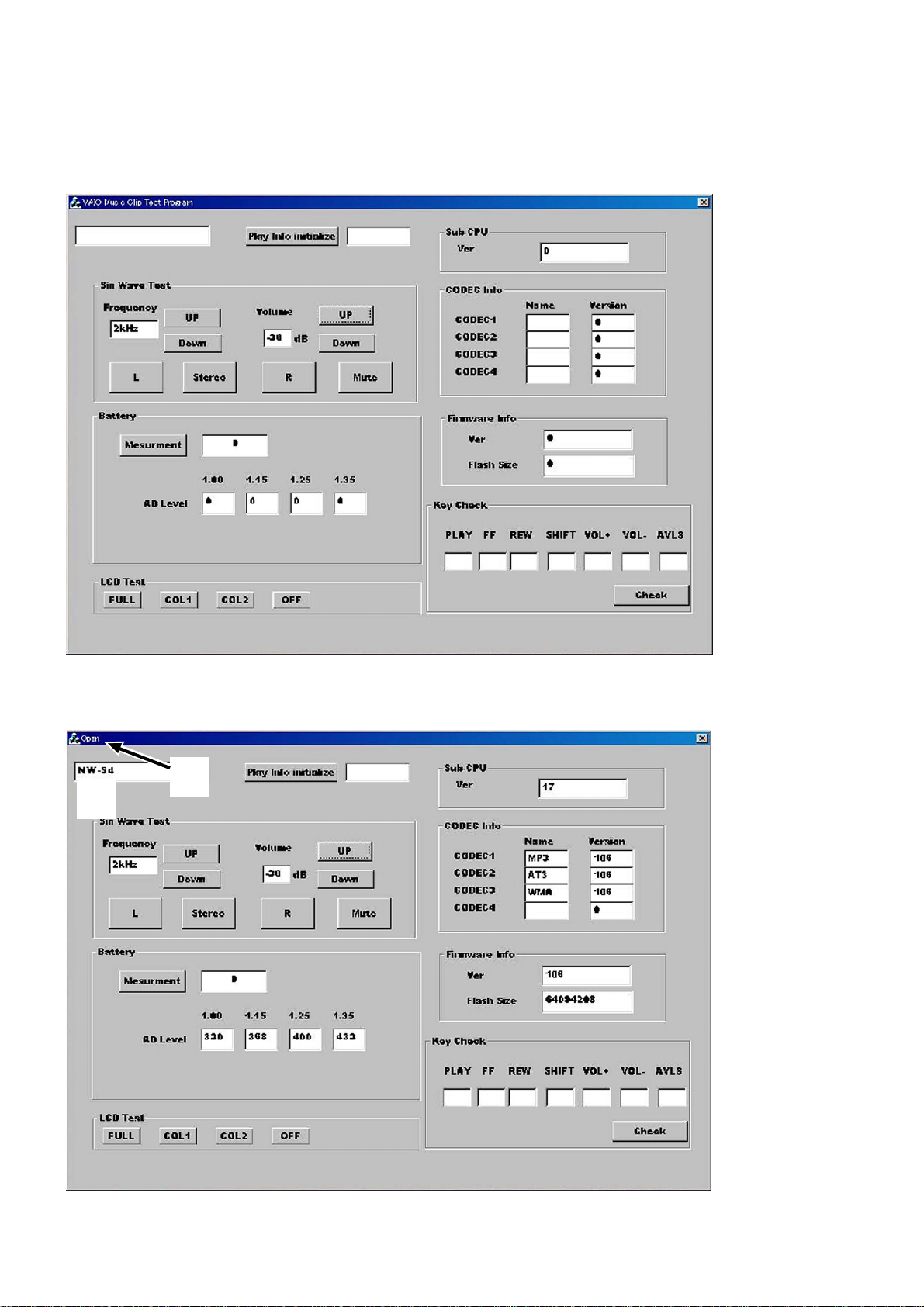
2. Start up the test mode “” of the service tool ( ) from the PC, and check that the following screen
appears.
3. Connect PC to this set with a USB cable. Check that the block 1 of the following screen “open”, and “1PC” is displayed on the LCD
of the set. (The block 1 will “close” if the set is disconnected again)
At this time, a sine wave is outputted from the headphone. Also, the model name is displayed in the block 7 of the screen.
1
7
Note: If the block 1 does not “open”, the circuits in MAIN board will be faulty. A udio signals are outputted from the r eference signal in the DSP of
the set.
4
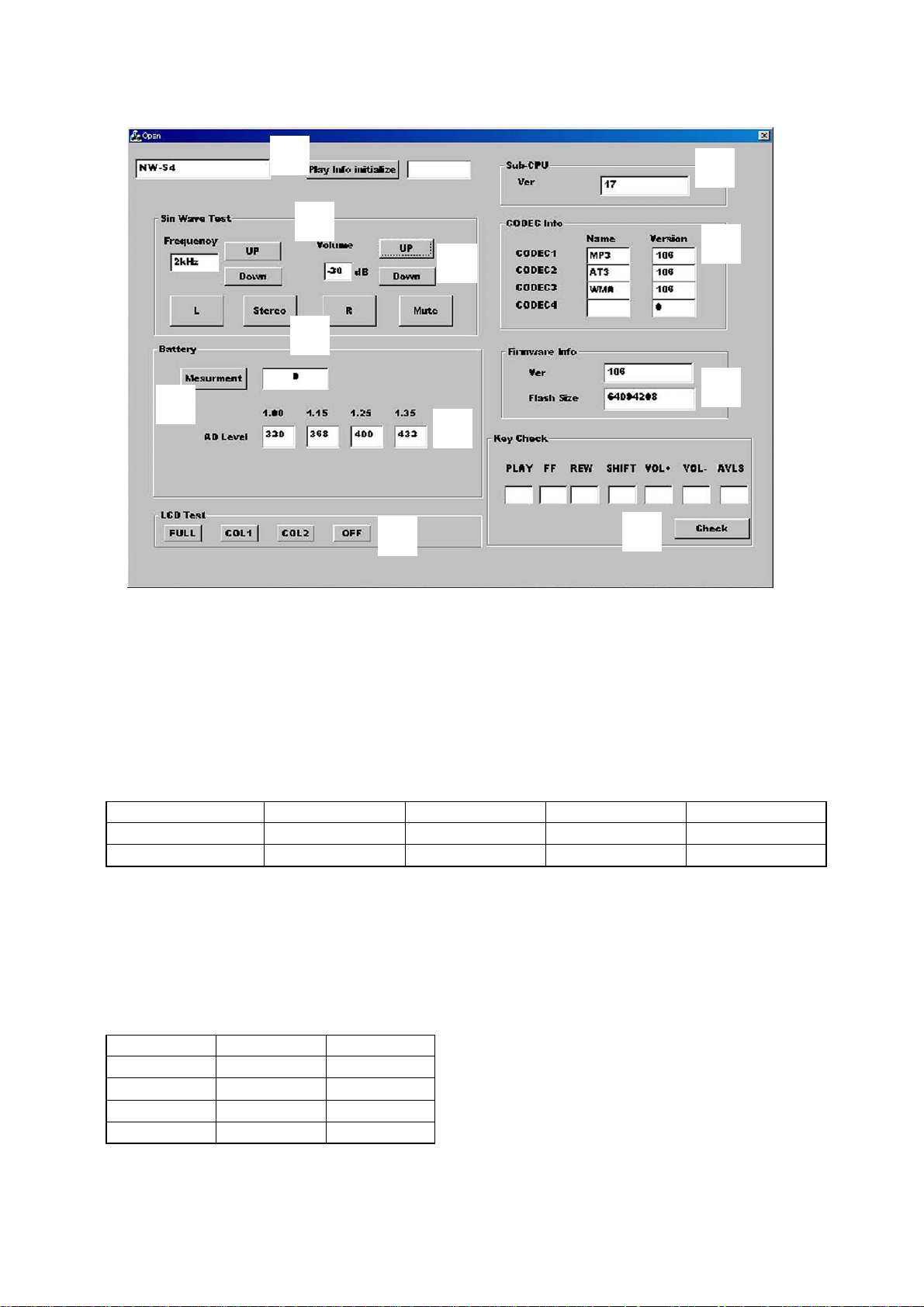
Operational description of Test mode
NW-S4
6
qd
2
4
8
qa
9
3
0
5
qs
1. Audio Block Function Check
Clicking the UP or Down button in block 2 of the screen allows you to check with various output frequencies. Also, clicking the UP or
Down button in block 3 can check variations of volume. Clicking the L, Stereo, R, or Mute button in block 4 can change audio output
status.
2. Battery Threshold Value Check
Connect PC to this set with a USB cable, and the threshold values of battery residual capacity (voltage-con verted v alues) written to the set
at the shipment are displayed in the block 5.
Check that the displayed values are same as listed in Table 1-3.
Table 1-3.
Condition Capacity 1→OFF Capacity 2→1 Capacity 3→2 Capacity 4→3
Voltage set value 1.00V 1.15V 1.25V 1.35V
Converted value (ref.) 320 368 400 432
3. LCD Test
Clicking FULL (full lit), COL1 (column 1), COL2 (column 2), or OFF (full off) in block 8 results in all ON, column 1 ON, column 2 ON,
or all OFF of the LCD on the set respectively.
4. CODEC Info Check
The CODEC programs and their versions written to the set can be checked. (block 9)
The CODEC programs written to the set at the shipment are “MP3”, “ATRAC3”, and “WMA” and their versions are as listed below.
(Versions will vary if updated)
Program No. Name Version
CODEC1 MP3 106
CODEC2 AT3 106
CODEC3 WMA 106
CODEC4 blank 0
5

NW-S4
5. Firmware Info Check
The DSP program version and the flash memory capacity can be checked. (block 0)
The version at the shipment is as follows. (Versions will vary if updated)
Version 106
Flash memory size 64094208
6. Sub-CPU Info Check
The Sub-CPU program version can be checked. (block qa)
The version at the shipment is as follows. (Versions will vary if updated)
Version 17
7. Key Check
Click the block qs while pressing a key on the set, and “ON” is displayed in the block associated with the pressed key, so that the key
operation can be checked.
1-4. Required System Configuration
•IBM PC/AT and compatibles
CPU: MMX
above recommended)
Hard disk drive space: 20 MB and above (Free space is required,
depending on the version of Windows 98 and the size of the audio
data you are using.)
RAM: 64 MB and above
CD-ROM drive
Sound Board: Creative SoundBlaster 16 compatible
Default built-in USB port
• Operating system: The default installation of Windows
version (The product does not work on Windows 95/3.1 or Windows
NT. Not assured trouble-free if you use an upgrade version from
Windows 95/3.1 to Windows 98.)
• Display: SVGA (800 × 600 pixel) (supports High Color (16 bit) and
above)
• Internet access
Pentium 233 MHz and above (Pentium II 400 MHz and
98 English
1-5. Action if MAIN Board was Replaced
If the MAIN board was replaced, perform “1. Execution of Play Info Initialize” in work procedure provided below.
When the MAIN board was replaced, the set status is as listed in Table 1-4.
Table 1-4.
Board name Set status after board replacement
MAIN board Music data and music information data stored in the set are cleared and not restored.
Precautions
1. Do not disconnect the USB cable in the midway of work.
2. If the operation on the PC side is not accepted during work, disconnect the USB cable and close the “” file, then
restart from the beginning.
6

NW-S4
Work procedure
1. Execution of Play Info Initialize
If the MAIN board was replaced for repair, e xecute “Play Info Initialize” in block qd to return respecti ve functions to initial positions (see
Table 1-5).
Note: In executing the “Play Info Initialize”, set the slide switches to the following positions.
AVLS switch ..... NORM
HOLD switch .... OFF
Table 1-5.
Function Position
Play position Head of first music
VOL level 25
MEGA BASS OFF
PLAY MODE OFF
2. Check after Work
(1) After work, check that the set operates normally through the operation in 1-3. “Operation Check for Inspection (T est Mode)” (see page
3).
(2) Make sure that the check-out and check-in can be made using the PC applications “OpenMG Jukebox” (CODEC programs “MP3” and
“ATRAC3”) and “Windows Media Player 7” (CODEC program “WMA”). Also, make sure that the checked out data can be played
normally.
Note: Do not start up the “OpenMG Jukebox” and the “Windows Media Player 7” simultaneously.
(3) For an installation and acquisition method of “Windows Media Player 7” (CODEC program “WMA”), refer to the follo wing instruction.
Using Network Walkman in
combination with Windows
TM
Media
Player 7
If you install Microsoft Windows MediaTM Player 7,
you can transfer a WMA file to your Network
Walkman and play it back. Refer to the online help for
Windows Media Player 7 for detailed operations.
Playing back WMA files with Network
Walkman
Installing Windows Media Player 7 and the
dedicated plug-ins
• Refer to http://www.openmg.com/ for the details
• To use Windows Media Player 7 in combination
Transferring (copying) a WMA file to your
Network Walkman
Network Walkman can only playback those WMA
files that are listed in the "Available File Formats" in
the "Options" dialog box on Windows Media Player 7
and are of 64 to 160 kbps.
Notes
• If you check "Enable Personal Rights Management" on
• It may be impossible to transfer the music contents
on how to obtain Windows Media Player 7.
with your Network Walkman, you need to install
the dedicated plug-in software. This software has
been already installed when the NW-S4 driver was
installed using the enclosed OpenMG Jukebox CDROM.
the "CD Audio" tab in the "Options" dialog box when
recording a CD using Windows Media Player 7, the
music cannot be transferred to Network Walkman. To
enable the music transfer, remove the check mark when
recording the CD.
with copyright management information such as those
purchased via EMD.
Notes
• Songs checked-out
using the OpenMG
Jukebox (ATRAC3
and MP3) can also be
listened on the
Portable Device
screen of Windows
Media Player 7, but
they can not be played
back nor checked-in to
Windows Media
Player 7.
• The transferred
(copied) WMA files to
Network Walkman
from Windows Media
Player 7 are shown on
the OpenMG Jukebox
) mark and
with a (
you can not playback
nor check-in them to
the OpenMG Jukebox.
1
Start Windows Media Player 7 and click on the
"Portable Device" tab.
The "Portable Device" screen appears.
Copy Music button
Portable
Device tab
2
Connect your Network Walkman to the computer
(See page 9).
The computer recognizes your Network Walkman and
the songs downloaded in Network Walkman are
shown on the "Music On Device" window of Windows
Media Player 7. If the computer can not recognize
your Network Walkman, press the F5 key.
3
Transfer (copy) the songs to your Network
Walkman.
Select a WMA file you want to transfer (copy) to your
Network Walkman and click on the "Copy Music"
button on Windows Media Player 7 window.
This starts copying the selected song and its title is
added to the "Music On Device" window.
Refer to the online help of Windows Media Player 7
for details on copying music to a portable device.
Portable
Device
screen
16
17
7

NW-S4
SECTION 2
GENERAL
Parts and controls
Refer to the page numbers indicated in parentheses for details.
This section is extracted from
instruction manual.
1 VOL (volume) +/– (page 10)
2 Display (page 11)
3 SHIFT button (pages 12, 13)
4 N/x (play/stop) button
(page 10)
5 ./> (MEGA BASS/MODE)
buttons (pages 11, 12, 13)
6 Battery compartment
(page 7)
7 Strap holder
8 HOLD switch (page 14)
9 Headphones jack (page 10)
0 AVLS switch (page 14)
qa USB connector (page 9)
6
8
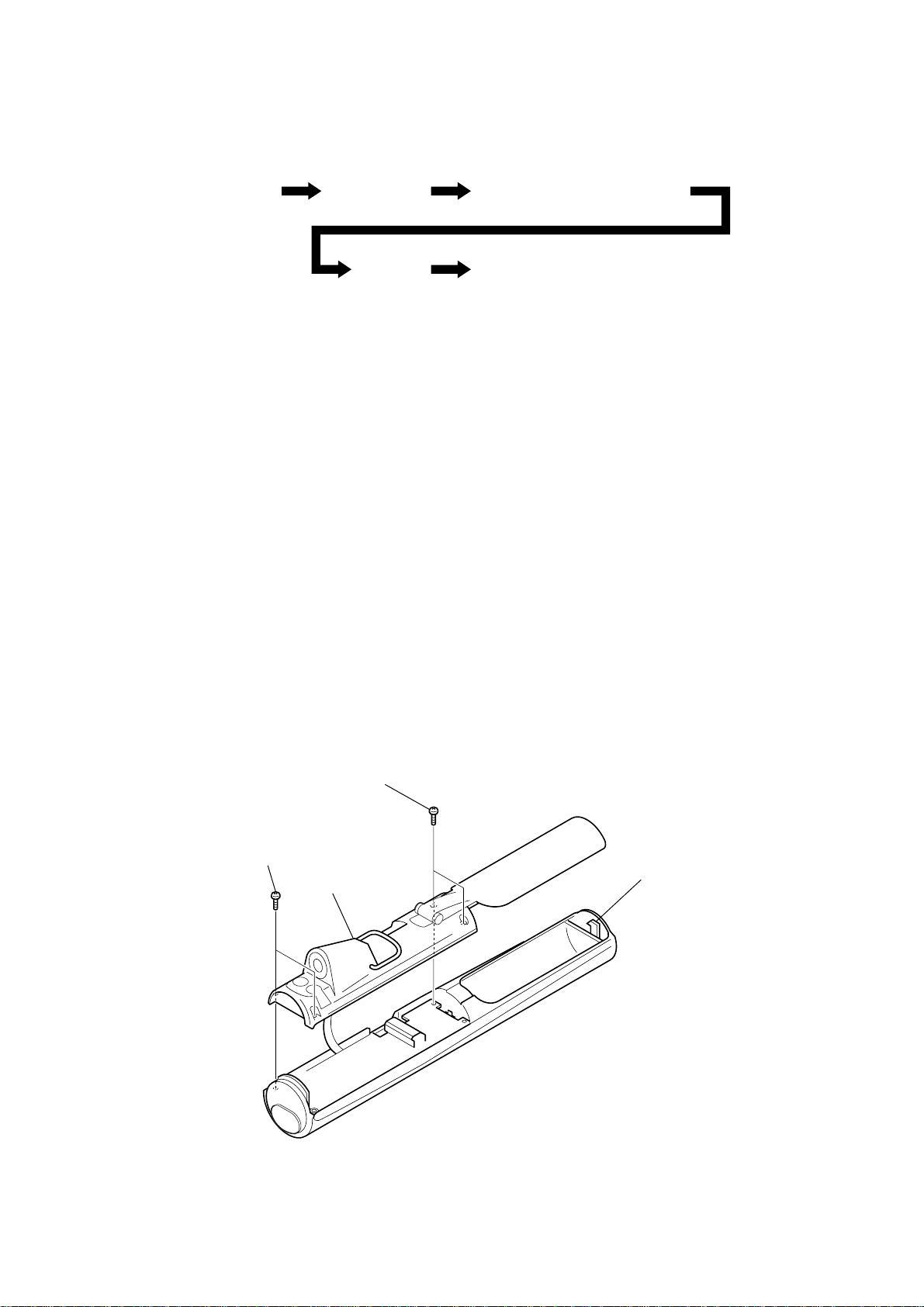
• This set can be disassembled in the order shown below.
d
3-1. DISASSEMBLY FLOW
NW-S4
SECTION 3
DISASSEMBLY
Set Lower case assy
Main board Sub board
Jack flexible module,
Jack (small type) (waterproof) (J301)
Note: Follow the disassembly procedure in the numerical order given.
3-2. LOWER CASE ASSY
1
two screws
(1.7
×
6)
1
two screws
×
6)
(1.7
3
lower case assy
2
lock knob (battery lid)
Note: This set is a drip-proof type.
Make it sure that no gaps on the
exterior of the set or no looseness
of screws exsist after repairing an
re-assembling the set.
Check it again before shipping.
9
NW-S4
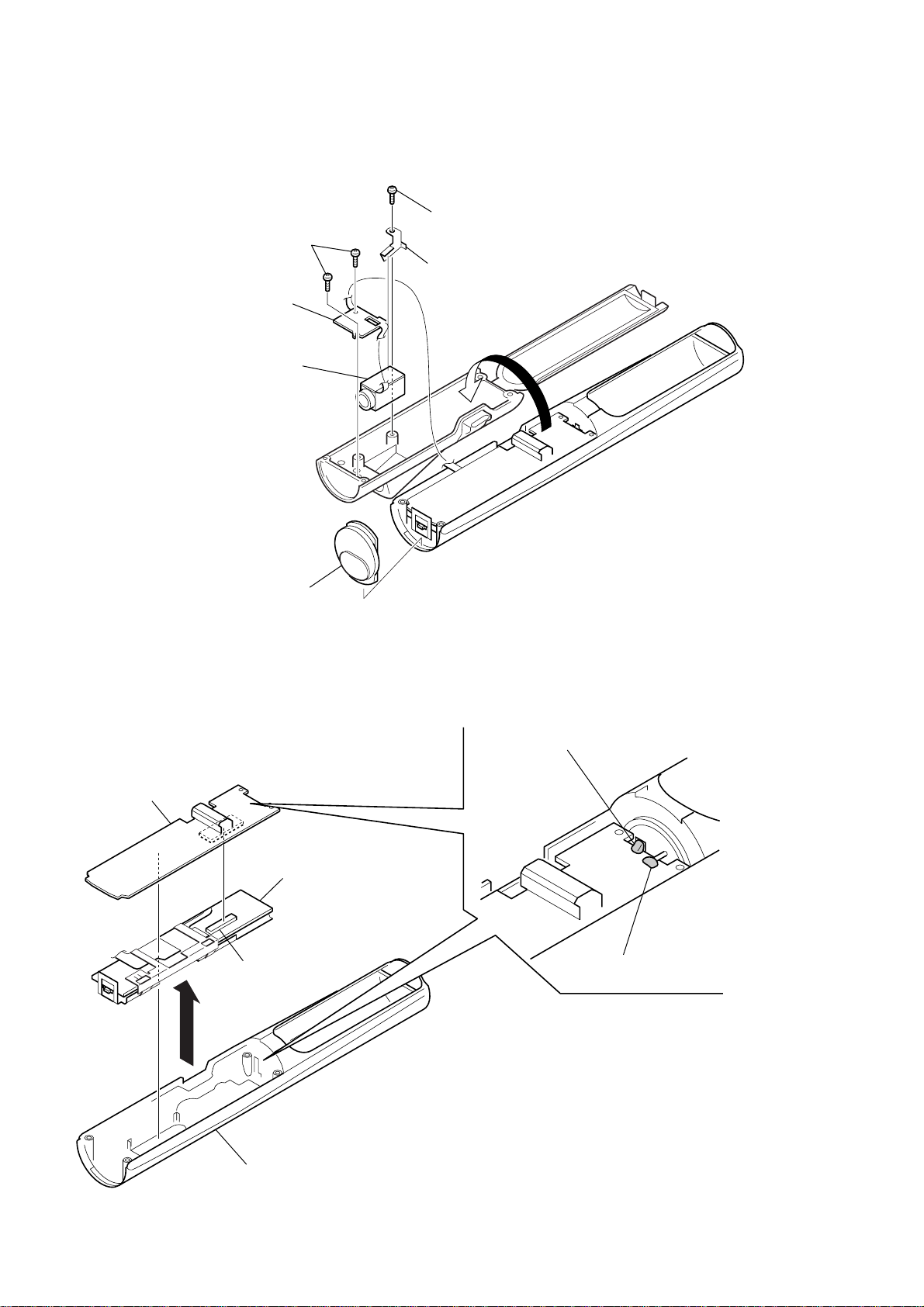
3-3. JACK FLEXIBLE MODULE, JACK (SMALL TYPE) (WATERPROOF) (J301)
5
3
4
jack flexible module
7
jack (small type) (waterproof)
(J301)
two screws
×
2.5)
(1.7
screw
(1.7
6
retainer (jack)
×
2.5)
1
3-4. MAIN BOARD
5
MAIN board
2
3
P cover assy
SUB board
4
connector
(CN802)
1
Remove the solder of battery terminal (+).
2
Remove the solder of battery terminal (–).
10
upper case assy
 Loading...