

Sony NWHD-1 Service manual
NW-HD1
SERVICE MANUAL
Ver 1.0 2004.07
• SonicStage and SonicStage logo are trademarks or registered
trademarks of Sony Corporation.
• OpenMG, ATRAC3, ATRAC3plus and their logos are trademarks
of Sony Corporation.
• Microsoft, Windows, Windows NT and Windows Media are
trademarks or registered trademarks of Microsoft Corporation in
the United States and/or other countries.
• IBM and PC/A T are registered trademarks of International Business
Machines Corporation.
• Macintosh is a trademark of Apple Computer, Inc. in the United
States and/or other countries.
• Pentium is a trademark or a registered trademark of Intel
Corporation.
• Adobe and Adobe Reader are trademarks or registered trademarks
of Adobe Systems Incorporated in the United States and/or other
countries.
• US and foreign patents licensed from Dolby Laboratories.
• All other trademarks and registered trademarks are trademarks or
registered trademarks of their respective holders.
• In this manual, TM and ® marks are not specifi ed.
Maximum recordable number of track
(Approx.)*
ATRAC3 ATRAC3plus
5,000 (132 kbps) 2,500 (256 kbps)
6,000 (105 kbps) 10,000 (64 kbps)
10,000 (66 kbps) 13,000 (48 kbps)
* When transferring four-minute tracks
Sampling frequency
44.1 kHz
Audio compression technology
Adaptive Transform Acoustic Coding3 (ATRAC3),
Adaptive Transform Acoustic Coding3plus
(ATRAC3plus)
Frequency response
20 to 20,000 Hz
(single signal measurement during playback)
Output
i
(headphones)/LINE OUT* :
Stereo minijack/194 mV
* The jack is used for both headphones and LINE
OUT.
Operating temperature
5 to 35ºC (41 to 95ºF)
Power source
DC IN 6 V (from built-in rechargeable battery)
Battery life (continuous playback)
ATRAC3plus format (48 kbps): Approx. 30 hours
SPECIFICATIONS
Dimension
Not including projecting parts:
89.0 × 62.1 × 13.8 (the thinnest part 12.6) mm
(3 5/8 × 2 1/2 × 9/16 (the thinnest part 1/2)
inches) (w/h/d)
Including projecting parts:
89.2 × 63.4 × 14.3 mm
(3 5/8 × 2 1/2 × 19/32 inches) (w/h/d)
Mass
Approx. 110 g (3.9 oz)
US and foreign patents licensed from Dolby
Laboratories.
Supplied accessories
• Headphones (1)
• USB cradle (1)
• Dedicated USB cable (1)
• AC power adaptor (1)
(For the supplied USB cradle)
• Carrying pouch (1)
• CD-ROM (1) *
(SonicStage, PDF of Operating Instructions)
• Quick Start Guide (1)
* Do not play this CD-ROM on an audio CD player.
Design and speci cations are subject to change
without notice.
US Model
AEP Model
UK Model
9-879-079-01
2004G05-1
© 2004.07
PORTABLE HARD DISK AUDIO PLAYER
Sony Corporation
Personal Audio Company
Published by Sony Engineering Corporation

NW-HD1
Notes on the AC power adaptor
Use only the AC power adaptor and USB
cradle supplied with the player. Do not use
any other AC power adaptor since this may
cause the player to malfunction.
The player is not disconnected from the
AC power source (mains) as long as it is
connected to the wall outlet, even if the
player itself has been turned off.
If you are not going to use the player for a
long time, be sure to disconnect the power
supply. To remove the AC power adaptor
from the wall outlet, grasp the adaptor plug
itself; never pull the cord.
Notes on chip component replacement
• Never reuse a disconnected chip component.
• Notice that the minus side of a tantalum capacitor may be
damaged by heat.
Flexible Circuit Board Repairing
• Keep the temperature of the soldering iron around 270 ˚C
during repairing.
• Do not touch the soldering iron on the same conductor of the
circuit board (within 3 times).
• Be careful not to apply force on the conductor when soldering
or unsoldering.
TABLE OF CONTENTS
1. SERVICING NOTES ............................................... 3
2. GENERAL ................................................................... 4
3. DISASSEMBLY
3-1. Disassembly Flow ........................................................... 5
3-2. Cabinet (Upper) Sub Assy............................................... 5
3-3. Cabinet (Lower) Assy...................................................... 6
3-4. Battery Block Sub Assy................................................... 6
3-5. MAIN Board.................................................................... 7
3-6. LCD Block Sub Assy ...................................................... 7
3-7. HDD Unit, HDD Board ................................................... 8
4. TEST MODE.............................................................. 9
5. DIAGRAMS
5-1. Block Diagram –MAIN Section (1/2) – .......................... 16
5-2. Block Diagram –MAIN Section (2/2) – .......................... 17
5-3. Block Diagram –KEY/POWER SUPPLY Section – ....... 18
5-4. Printed Wiring Board
– MAIN Section (Component Side) – ............................. 20
5-5. Printed Wiring Board
– MAIN Section (Conductor Side) –............................... 21
5-6. Schematic Diagram –MAIN Section (1/7) – ................... 22
5-7. Schematic Diagram –MAIN Section (2/7) – ................... 23
5-8. Schematic Diagram –MAIN Section (3/7) – ................... 24
5-9. Schematic Diagram –MAIN Section (4/7) – ................... 25
5-10. Schematic Diagram –MAIN Section (5/7) –................... 26
5-11. Schematic Diagram –MAIN Section (6/7) –................... 27
5-12. Schematic Diagram –MAIN Section (7/7) –................... 28
5-13. Printed Wiring Board – HDD Section – ......................... 29
5-14. Schematic Diagram – HDD Section –............................ 29
SAFETY-RELATED COMPONENT WARNING!!
COMPONENTS IDENTIFIED BY MARK 0 OR DOTTED LINE
WITH MARK 0 ON THE SCHEMATIC DIAGRAMS AND IN
THE PARTS LIST ARE CRITICAL TO SAFE OPERATION.
REPLACE THESE COMPONENTS WITH SONY PARTS WHOSE
PART NUMBERS APPEAR AS SHOWN IN THIS MANUAL OR
IN SUPPLEMENTS PUBLISHED BY SONY.
6. EXPLODED VIEW ................................................... 42
7. ELECTRICAL PARTS LIST................................ 43
2

SECTION 1
SERVICING NOTES
NW-HD1
UNLEADED SOLDER
Boards requiring use of unleaded solder are printed with the leadfree mark (LF) indicating the solder contains no lead.
(Caution: Some printed circuit boards may not come printed with
the lead free mark due to their particular size)
: LEAD FREE MARK
Unleaded solder has the following characteristics.
• Unleaded solder melts at a temperature about 40 ˚C higher
than ordinary solder.
Ordinary soldering irons can be used but the iron tip has to be
applied to the solder joint for a slightly longer time.
Soldering irons using a temperature regulator should be set to
about 350 ˚C.
Caution: The printed pattern (copper foil) may peel away if
the heated tip is applied for too long, so be careful!
• Strong viscosity
Unleaded solder is more viscou-s (sticky, less prone to flow)
than ordinary solder so use caution not to let solder bridges
occur such as on IC pins, etc.
• Usable with ordinary solder
It is best to use only unleaded solder but unleaded solder may
also be added to ordinary solder.
• Replacement of CXR704060-201GA (IC1003),
MBM29SL800BE-90PBT (IC1101), S1R72003BOOA100
(IC2001), CXR710160-211GH (IC3001), CXD1616GH
(IC7001) and EDL1216CASA-10L-E (IC7002) used in this
set requires a special tool.
System requirements
Computer
Operating System
Display
Others
Notes
•
SonicStage is not supported by the following environments:
– Operating systems other than those the indicated above
– Personally constructed PCs or operating systems
– An environment that is an upgrade of the original manufacturer-installed operating system
– Multi-boot environment
– Multi-monitor environment
– Macintosh
•
We do not guarantee trouble-free operation on all computers that satisfy the system requirement.
•
The NTFS format of Windows XP/Windows 2000 Professional can be used only with the standard (factory)
settings.
•
For Windows 2000 Professional users, install Service Pack 3 or later version before using the software.
•
We do not guarantee trouble-free operation of the system suspend, sleep, or hibernation function on the
computers.
IBM PC/AT or Compatible
• CPU: Pentium II 400 MHz or higher (Pentium III 450 MHz or higher is
recommended.)
• Hard disk drive space: 200 MB or more (1.5 GB or more is recommended.) (The
amount of space will vary according to the Windows version and the number of
music les stored on the hard disk.)
• RAM: 64 MB or more (128 MB or more is recommended.)
Others • CD drive (capable of digital playback by WDM)
• Sound Board
• USB port (Hi-Speed USB is supported.)
Factory installed:
Windows XP Media Center Edition 2004/Windows XP Media Center Edition/
Windows XP Professional/Windows XP Home Edition/Windows 2000 Professional/
Windows Millennium Edition/Windows 98 Second Edition
High Color (16 bit) or higher, 800 600 dots or better (1024 × 768 dots or better is
recommended.)
• Internet access: for Web registration, EMD services and CDDB
• Windows Media Player (version 7.0 or higher) installed for playing WMA les
3
NW-HD1
SECTION 2
GENERAL
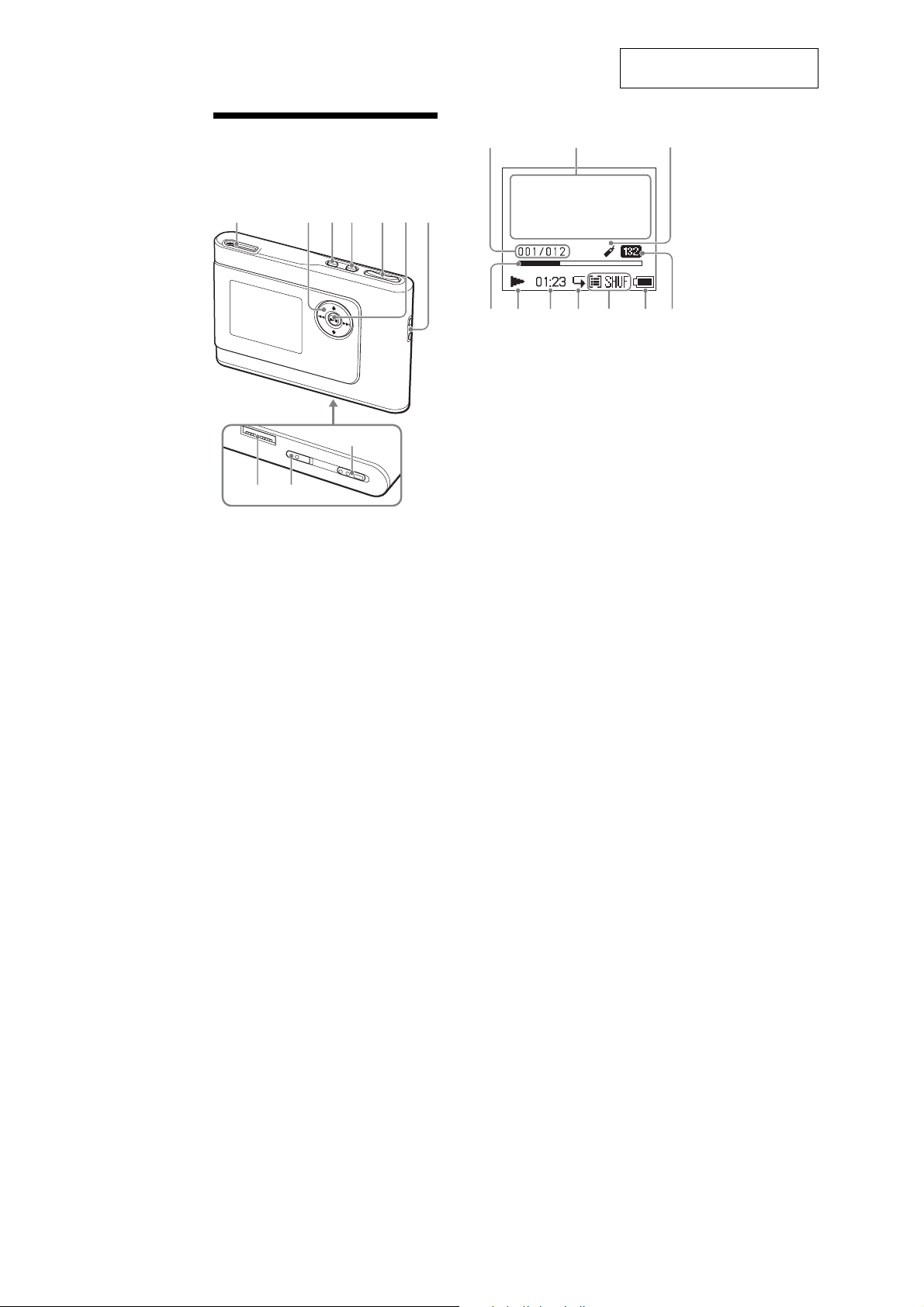
Guide to Parts and
Controls
Player
1234567
q;
8
9
1i
(headphones)/LINE OUT jack
2M, m, ., >
3
MENU button
4
MODE button
5
VOLUME +*/– buttons
6Nx
(play/stop) button
7
Hole for hand strap**
8
USB cradle connector
9
BUILT-IN BATTERY switch
q;
HOLD switch
* This button has a tactile dot.
** You can attach your own hand strap.
buttons
This section is extracted from
instruction manual.
Player display
qa qs
qf qg qh qj qk w;ql
qa
Track number indicator
qs
Character information display
qd
Bookmark indicator
qf
Playback progress bar
qg
Playback indicator
qh
Playing time
qj
Repeat indicator
qk
Play mode indicator
Sound indicator
ql
Battery indicator
w;
Bit rate
qd
About the serial number
The serial number provided for this player is
required for the customer registration. The
number is on a label on the rear of the player.
4
• This set can be disassembled in the order shown below.
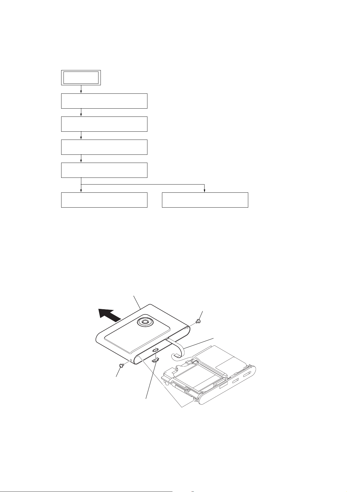
3-1. DISASSEMBLY FLOW
SET
3-2. CABINET (UPPER) SUB ASSY
(Page 5)
3-3. CABINET (LOWER) ASSY
(Page 6)
3-4. BATTERY BLOCK SUB ASSY
(Page 6)
3-5. MAIN BOARD
(Page 7)
NW-HD1
SECTION 3
DISASSEMBLY
3-6. LCD BLOCK SUB ASSY
(Page 7)
Note: Follow the disassembly procedure in the numerical order given.
3-7. HDD UNIT, HDD BOARD
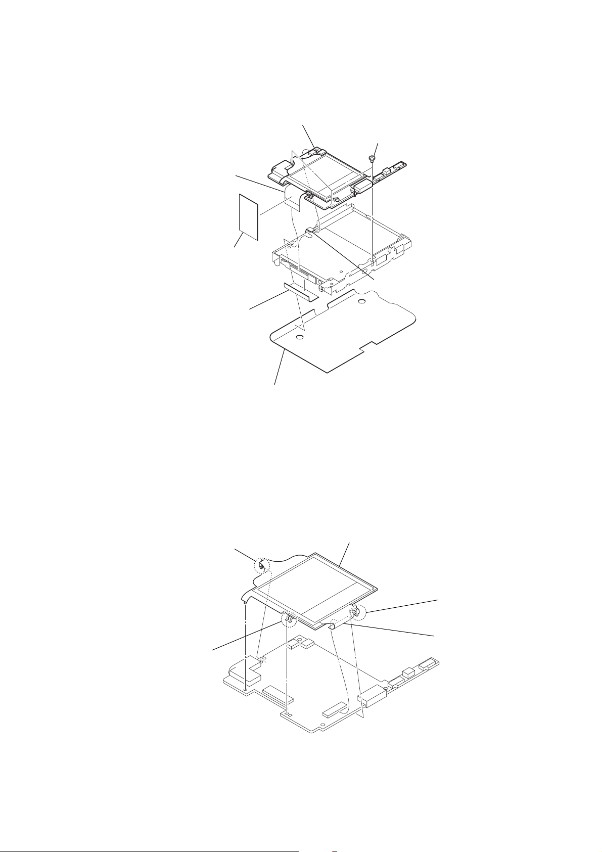
3-2. CABINET (UPPER) SUB ASSY
6
cabinet (upper) sub assy
3
(Page 8)
2
screw (M1.4)
5
flexible board
(CN5002)
1
screw (M1.4)
4
escutcheon (cradle)
5
NW-HD1
)
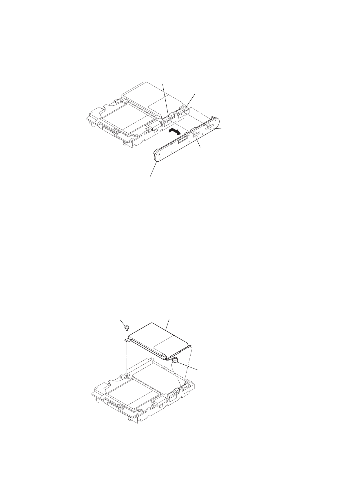
3-3. CABINET (LOWER) ASSY
Note :When install the cabinet (lower) assy,
adjust the position of two switches (S5009, S9501)
and knob (batt, hold).
S9501
S5009
1
Remove the cabinet (lower)
assy in the direction of arrow.
knob (hold)
knob (batt)
3-4. BATTERY BLOCK SUB ASSY
2
toothed lock screw (M1.4)
3
battery block sub assy
1
connector (CN9501
6
3-5. MAIN BOARD
3
sheet (insulating HDD flexible)
4
flexible board
(CN100)
2
7
sheet
(SHIELD HDD)
MAIN board
6
three toothed screws (M1.4)
5
flexible board
(CN5003)
NW-HD1
3-6. LCD BLOCK SUB ASSY
3
1
Remove two solders.
claw
1
sheet (damper)
4
LCD block sub assy
2
claw
5
flexible board
(CN5001)
7

NW-HD1
3-7. HDD UNIT, HDD BOARD
1
Remove the HDD unit in the direction of arrow.
2
HDD board
Note : Extraction and insertion of a HDD board is
performed perpendicularly.
8
SECTION 4
TEST MODE
NW-HD1
1. OUTLINE
For the LCD display , the LCD on the remote commander is shown,
but the contents of LCD display on the main unit are same.
Power supply voltage : 3.65 to 3.75 V
Volume : 24
SOUND EQ : OFF
AVLS : OFF
[HOLD] switch : OFF
Set states : horizontal states
2. SETTING THE TEST MODE
1. Supply power to the set.
2. Switch-on the [HOLD] switch on the main unit.
3. Operate as follows.
• When use only main unit
While pressing the [MODE] key on the main unit, press the key on
the main unit as following order.
> → > → . → . → > → . → > → .
→ M → m
• When use the main unit and remote commander
While pressing the [MODE] key on the main unit, press the key on
the remote commander as following order.
> → > → . → . → > → . → > → .
→ + → –
4. Switch-off the [HOLD] switch on the main unit and enter the
test mode.
3. RELEASING THE TEST MODE
Press the [SET UP] key on the main unit or
commander for 1.5 seconds or more, turn off the power and release
the test mode.
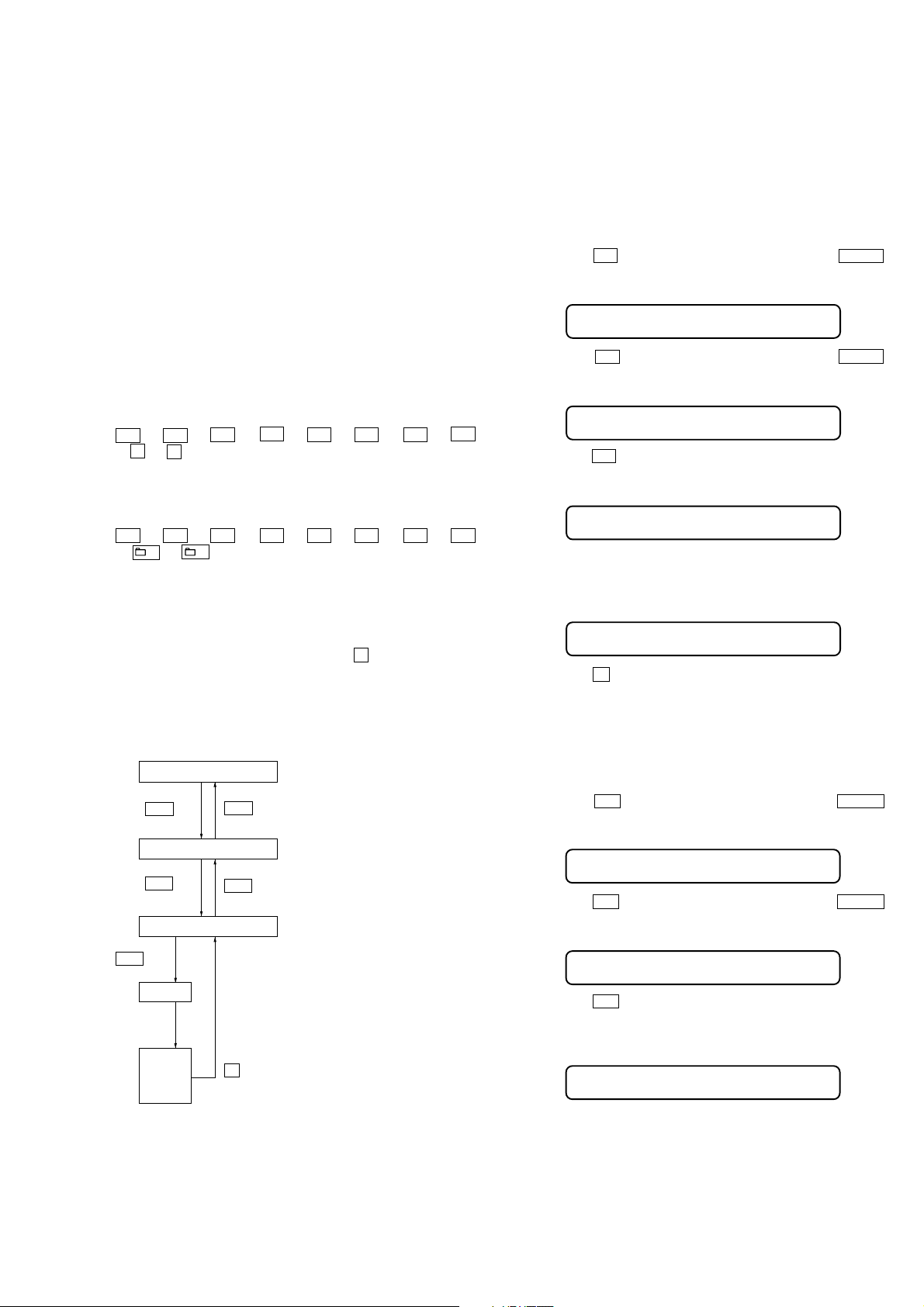
4. CONFIGURATION OF THE TEST MODE
Flow of the test mode:
F/W version display
>
>
u
jog
Start
Automatic
Finish
Result
jog
Major item
jog
Minor item
or
.
.
x
jog
Major item switching:
jog
Minor item switching:
key
x key on the remote
[VOL +/--]
[VOL +/--]
jog
jog
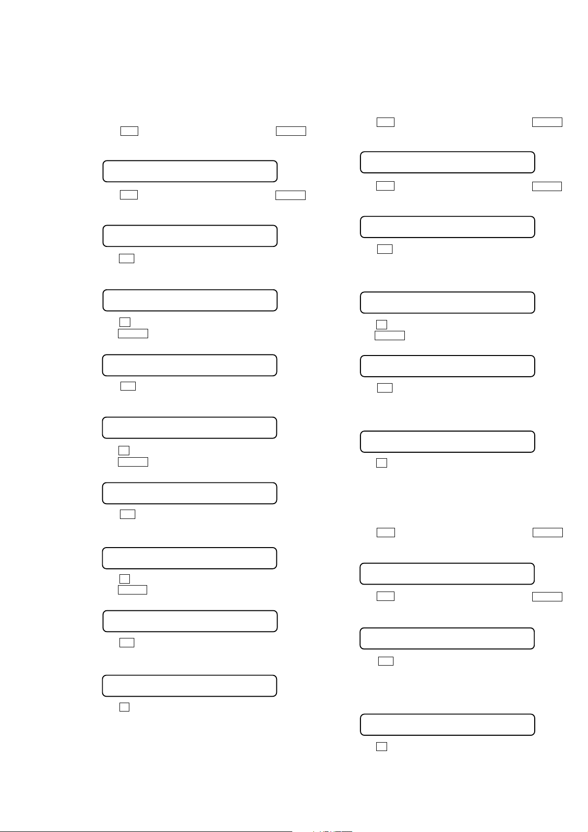
5. OPERATION OF THE TEST MODE
5-1. Power
5-1-1. Power supply voltage check
This mode is used in case power supply voltage in the state where
all power supply lines (1.2 V/1.5 V/1.8 V/2.0 V/2.4 V/3.3 V/VSTBY/
VDC) are starting is checked.
Checking method:
1. Enter the test mode.
2. Press the > jog to display major item, and turn the VOL +/–
jog to select the “POWER”.
LCD display of the remote commander
POWER
3. Press the > jog to display minor item, and turn the VOL +/–
jog to select the “V CHK”.
LCD display of the remote commander
V CHK
4. Press the u jog, “START” is displayed and all power supply
lines are started.
LCD display of the remote commander
START
5. Press the [DISPLAY] key, “HD OFF/ON” is displayed. Each time
[DISPLAY] key is pressed, hard disk drive power supply ON/
OFF switch is performed.
LCD display of the remote commander
HD OFF/ON
6. Press the x key, return to minor item selection screen.
5-1-2. Consumption current (read state) check
This mode is used in case consumption current (read state) in the
state where the hard disk drive has booted is checked.
Checking method:
1. Enter the test mode.
2. Press the > jog to display major item, and turn the VOL +/–
jog to select the “POWER”.
LCD display of the remote commander
POWER
3. Press the > jog to display minor item, and turn the VOL +/–
jog to select the “A RD”.
LCD display of the remote commander
A RD
4. Press the u jog, “READY?” is displayed. In this state, Each
time [DISPLAY] key is pressed, EL back light ON/OFF switch
is performed.
LCD display of the remote commander
READY?
9

NW-HD1
5. Press the u jog, “READ” is displayed and hard disk drive
becomes read state.
After 10 seconds, “FIN” is displayed automatically and read
state is completed.
LCD display of the remote commander
READ
r
FIN
6. Press the x key, return to minor item selection screen.
5-1-3. Consumption current (write state) check
This mode is used in case consumption current (write state) in the
state where the hard disk drive has booted is checked.
Checking method:
1. Enter the test mode.
2. Press the
jog to select the “POWER”.
> jog to display major item, and turn the VOL +/–
LCD display of the remote commander
POWER
3. Press the > jog to display minor item, and turn the VOL +/–
jog to select the “A WR”.
LCD display of the remote commander
A WR
4. Press the u jog, “READY?” is displayed. In this state, Each
time [DISPLAY] key is pressed, EL back light ON/OFF switch
is performed.
LCD display of the remote commander
READY?
5. Press the u jog, “WRITE” is displayed and hard disk drive
becomes write state.
After 10 seconds, “FIN” is displayed automatically and write
state is completed.
LCD display of the remote commander
WRITE
r
FIN
6. Press the x key, return to minor item selection screen.
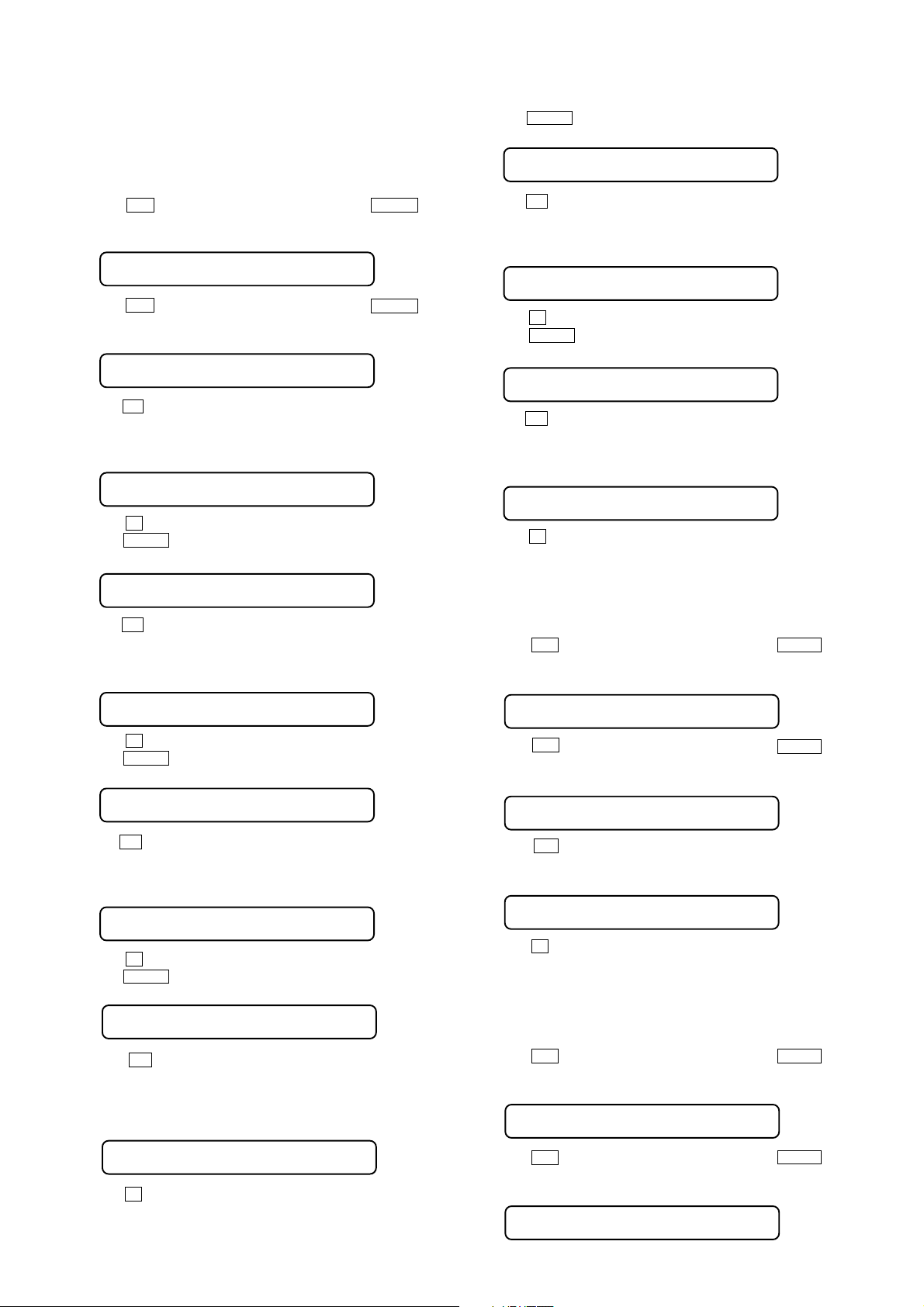
5-2. Audio
The VOLUME + key on the main unit or [PLAY MODE] on the remote
commander performs switch of HP/LINE.
While playing the audio track, it's in a repeat state. If x key is
pressed, it’s stopped.
Setting method of the audio test mode:
1. The data for audio test mode is copied to hard disk drive.
2. Enter the test mode.
3. Press the > jog to display major item, and turn the VOL +/–
jog to select the “AUDIO”.
LCD display of the remote commander
AUDIO
4. Press the
jog to select the “TESTLD”.
> jog to display minor item, and turn the VOL +/–
LCD display of the remote commander
TESTLD
5. Press the u jog, “START” is displayed. Then automatically
reboot.
LCD display of the remote commander
START
6. After reboot, narrowing-down screen “Artist” is checked and
enter the test mode.
Audio test mode (5-2-1 to 5-2-8) is performed in this state.
5-2-1. Output check
“1 kHz 0 dBs L-ch/R-ch” audio signal is outputted.
Checking method:
1. Enter the audio test mode.
2. Press the
jog to select the “AUDIO”.
> jog to display major item, and turn the VOL +/–
LCD display of the remote commander
AUDIO
3. Press the > jog to display minor item, and turn the VOL +/–
jog to select the “OUTPUT”.
LCD display of the remote commander
OUTPUT
4. Press the u jog, “START” is displayed and “1 kHz 0 dBs
L-ch/R-ch” audio signal is outputted. In this state, Each time
[DISPLAY] key is pressed, MUTE ON/OFF switch is performed.
LCD display of the remote commander
START
5. Press the x key, return to minor item selection screen.
5-2-2. S/N check
“Infinity Zero” audio signal is outputted.
Checking method:
1. Enter the audio test mode.
2. Press the > jog to display major item, and turn the VOL +/–
jog to select the “AUDIO”.
LCD display of the remote commander
AUDIO
3. Press the > jog to display minor item, and turn the VOL +/–
jog to select the “SN”.
LCD display of the remote commander
SN
4. Press the u jog, “START” is displayed and “Infinity Zero”
audio signal is outputted.
LCD display of the remote commander
START
5. Press the x key, return to minor item selection screen.
10
NW-HD1
5-2-3. Frequency characteristic check
“20 Hz/20 kHz/100 Hz/10 kHz 0 dBs L-ch/R-ch” audio signal is
outputted.
Checking method:
1. Enter the audio test mode.
2. Press the
jog to select the “AUDIO”.
> jog to display major item, and turn the VOL +/–
LCD display of the remote commander
AUDIO
3. Press the > jog to display minor item, and turn the VOL +/–
jog to select the “F 1”.
LCD display of the remote commander
F 1
4. Press the u jog, “START” is displayed and “20 Hz 0 dB s
L-ch/R-ch” audio signal is outputted.
LCD display of the remote commander
START
5. Press the x key , retur n to minor item selection screen.
6. Turn the VOL +/– jog to select the “F 2”.
LCD display of the remote commander
5-2-4. Channel separation check
“1 kHz 0 dBs L-ch/1 kHz 0 dBs R-ch” audio signal is outputted.
Checking method:
1. Enter the audio test mode.
2. Press the
jog to select the “AUDIO”.
> jog to display major item, and turn the VOL +/–
LCD display of the remote commander
AUDIO
3. Press the > jog to display minor item, and turn the VOL +/–
jog to select the “SEP LR”.
LCD display of the remote commander
SEP LR
4. Press the u jog, “START” is displayed and “1 kHz 0 dBs
L-ch” audio signal is outputted. In this state, Each time
[DISPLAY] key is pressed, V -SUR switch is perfor med.
LCD display of the remote commander
START
5. Press the x key , return to minor item selection screen.
6. Turn the VOL +/– jog to select the “SEP RL”.
LCD display of the remote commander
F 2
7. Press the u jog, “START” is displayed and “20 kHz 0 dBs
L-ch/R-ch” audio signal is outputted.
LCD display of the remote commander
START
8. Press the x key , retur n to minor item selection screen.
9. Turn the VOL +/– jog to select the “F 3”.
LCD display of the remote commander
F 3
10. Press the u jog, “START” is displayed and “100 Hz 0 dBs
L-ch/R-ch” audio signal is outputted.
LCD display of the remote commander
START
11. Press the x key, return to minor item selection screen.
12. Turn the VOL +/– jog to select the “F 4”.
LCD display of the remote commander
F 4
13. Press the u jog, “START” is displayed and “10 kHz 0 dBs
L-ch/R-ch” audio signal is outputted.
LCD display of the remote commander
START
14. Press the x key, return to minor item selection screen.
SEP RL
7. Press the u jog, “START” is displayed and “1 kHz 0 dBs
R-ch” audio signal is outputted. In this state, Each time
[DISPLAY] key is pressed, V -SUR switch is perfor med.
LCD display of the remote commander
START
8. Press the x key , return to minor item selection screen.
5-2-5. Maximum output check
“1 kHz 0 dBs L-ch/R-ch VOLUME: 30” audio signal is outputted.
Checking method:
1. Enter the audio test mode.
2. Press the > jog to display major item, and turn the VOL +/–
jog to select the “AUDIO”.
LCD display of the remote commander
AUDIO
3. Press the > jog to display minor item, and turn the VOL +/–
jog to select the “MAXOUT”.
LCD display of the remote commander
MAXOUT
4. Press the u jog, “START” is displayed and “1 kHz 0 dBs
L-ch/R-ch VOLUME: 30” audio signal is outputted. In this
state, Each time [DISPLAY] key is pressed, AVLS ON/OFF
switch is performed.
LCD display of the remote commander
START
5. Press the x key , return to minor item selection screen
11
NW-HD1
5-2-6. SOUND EQ check
“100 Hz/250 Hz/630 Hz/1.6 kHz/4 kHz/10 kHz –20 dBs L-ch/Rch” audio signal is outputted.
Checking method:
1. Enter the audio test mode.
2. Press the
jog to select the “AUDIO”.
> jog to display major item, and turn the VOL +/–
LCD display of the remote commander
AUDIO
3. Press the > jog to display minor item, and turn the VOL +/–
jog to select the “EQ 1”.
LCD display of the remote commander
EQ 1
4. Press the u jog, “ST ART” is displayed and “100 Hz –20 dBs L-
ch/R-ch” audio signal is outputted. In this state, Each time [DISPLAY]
key is pressed, EQ MAX/MIN switch is performed.
LCD display of the remote commander
START
5. Press the x key, return to minor item selection screen..
6. Turn the VOL +/– jog to select the “EQ 2”.
LCD display of the remote commander
EQ 2
7. Press the u jog, “ST ART” is displayed and “250 Hz –20 dBs L-
ch/R-ch” audio signal is outputted. In this state, Each time [DISPLAY]
key is pressed, EQ MAX/MIN switch is performed.
LCD display of the remote commander
15. Turn the
VOL +/– jog to select the “EQ 5”.
LCD display of the remote commander
EQ 5
16. Press the u jog, “START” is displayed and “4 kHz –20 dBs L-
ch/R-ch” audio signal is outputted. In this state, Each time [DISPLAY]
key is pressed, EQ MAX/MIN switch is performed.
LCD display of the remote commander
START
17. Press the x key, return to minor item selection screen..
18. Turn the VOL +/– jog to select the “EQ 6”.
LCD display of the remote commander
EQ 6
19. Press the u jog, “ST AR T” is displayed and “10 kHz –20 dBs L-
ch/R-ch” audio signal is outputted. In this state, Each time [DISPLAY]
key is pressed, EQ MAX/MIN switch is performed.
LCD display of the remote commander
START
20. Press the x key, return to minor item selection screen.
5-2-7. BEEP check
BEEP sound is outputted.
Checking method:
1. Enter the audio test mode.
2. Press the
jog to select the “AUDIO”.
> jog to display major item, and turn the VOL +/–
LCD display of the remote commander
START
8. Press the x key, return to minor item selection screen..
9. Turn the VOL +/– jog to select the “EQ 3”.
LCD display of the remote commander
EQ 3
10. Press the u jog, “STAR T” is displayed and “630 Hz –20 dBs Lch/R-ch” audio signal is outputted. In this state, Each time [DISPLAY]
key is pressed, EQ MAX/MIN switch is performed.
LCD display of the remote commander
START
11. Press the x key, return to minor item selection screen..
12. Turn the VOL +/– jog to select the “EQ 4”.
LCD display of the remote commander
EQ 4
13. Press the u jog, “START” is displayed and “1.6 kHz –20
dBs L-ch/R-ch” audio signal is outputted. In this state, Each
time [DISPLAY] key is pressed, EQ MAX/MIN switch is
performed.
LCD display of the remote commander
START
14. Press the x key, return to minor item selection screen..
AUDIO
3. Press the > jog to display minor item, and turn the VOL +/–
jog to select the “BEEP”.
LCD display of the remote commander
BEEP
4. Press the u jog, “START” is displayed and BEEP sound is
outputted.
LCD display of the remote commander
START
5. Press the x key, return to minor item selection screen.
5-2-8. Sound pressure regulation level check
“1 kHz 0 dBs L-ch/R-ch” audio signal is outputted.
Checking method:
1. Enter the audio test mode.
2. Press the
jog to select the “AUDIO”.
> jog to display major item, and turn the VOL +/–
LCD display of the remote commander
AUDIO
3. Press the > jog to display minor item, and turn the VOL +/–
jog to select the “SPL”.
LCD display of the remote commander
12
SPL
NW-HD1
4. Press the u jog, “START” is displayed and “1 kHz 0 dBs
L-ch/R-ch” audio signal is outputted.
LCD display of the remote commander
START
5. Press the x key , retur n to minor item selection screen.
5-3. Others
5-3-1. G-sensor check
X/Y/Z-axis direction is checked.
Checking method:
1. Enter the test mode.
2. Press the
jog to select the “OTHERS”.
> jog to display major item, and turn the VOL +/–
LCD display of the remote commander
OTHERS
3. Press the > jog to display minor item, and turn the VOL +/–
jog to select the “G TEST”.
LCD display of the remote commander
G TEST
4. Press the u jog, X-axis direction is displayed.
LCD display of the remote commander
3. Press the > jog to display minor item, and turn the VOL +/–
jog to select the “CLOCK”.
LCD display of the remote commander
CLOCK
4. Press the u jo g, “STAR T” is displayed. Then “OK” or “NG”
is displayed automatically.
LCD display of the remote commander
START
r
OK
5. Press the x key , return to minor item selection screen.
5-3-3. Key check
LCD display corresponding to the pushed key is performed.
Checking method:
1. Enter the test mode.
2. Press the
jog to select the “OTHERS”.
> jog to display major item, and turn the VOL +/–
LCD display of the remote commander
OTHERS
X: ***
***
: A/D value (hexadecimal)
Note: “NG” is displayed when the G-sensor has broken (press the x key,
return to minor item selection screens).
LCD display of the remote commander
NG
5. Press the u jog, Y-axis direction is displayed (press the x
key, return to minor item selection screens).
LCD display of the remote commander
Y: ***
***
: A/D value (hexadecimal)
6. Press the u jog, Z-axis direction is displayed (press the x
key, return to minor item selection screens).
LCD display of the remote commander
Z: ***
***
: A/D value (hexadecimal)
7. Press the x key , retur n to minor item selection screen.
5-3-2. Clock check
Clock operation is checked.
Checking method:
1. Enter the test mode.
2. Press the > jog to display major item, and turn the VOL +/–
jog to select the “OTHERS”.
LCD display of the remote commander
OTHERS
3. Press the > jog to display minor item, and turn the VOL +/–
jog to select the “KEY CH”.
LCD display of the remote commander
KEY CH
4. Press the u jog, “START” is displayed and LCD display
corresponding to the pushed key is performed.
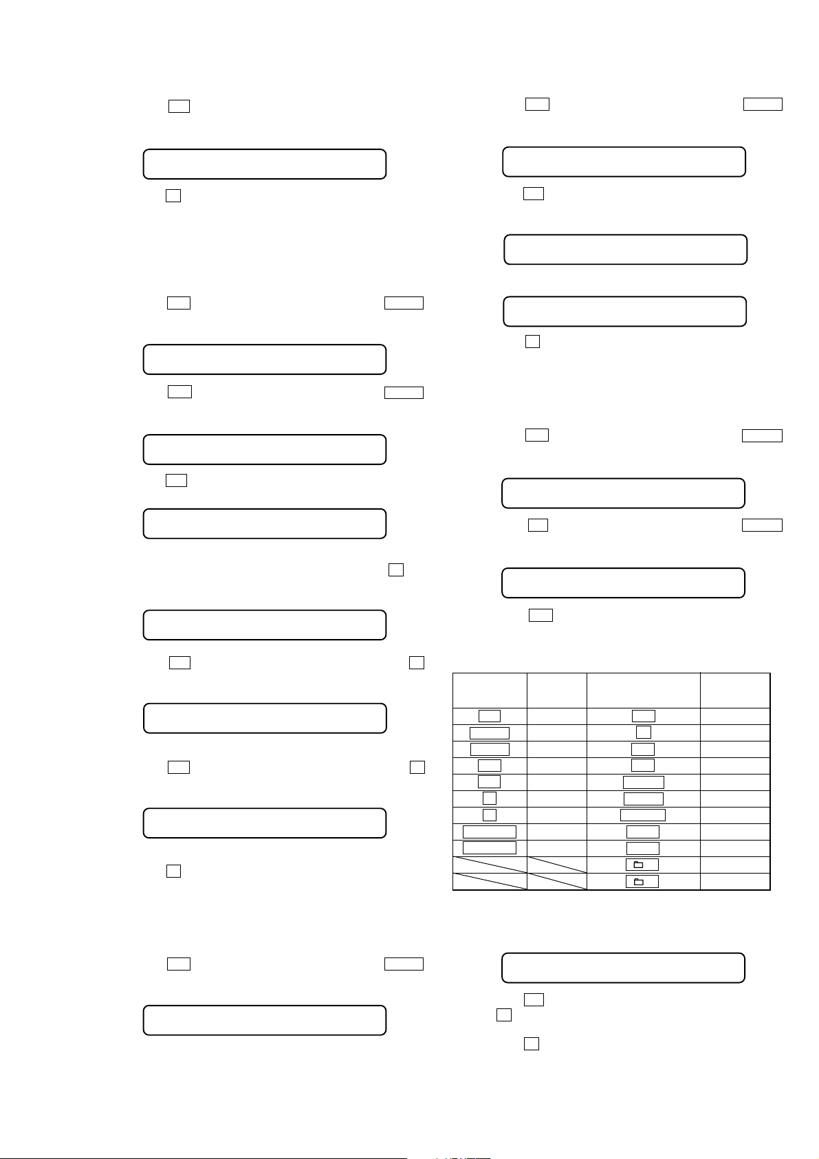
Press on all the keys of main unit displays “SET OK”.
Press on all the keys of remote commander displays “RMC OK”.
Key of LCD Key of LCD
main unit display remote commander displa y
Bx PLAY u R PLAY
SET UP SETUP x R STOP
MODE MODE > R FR
> FF . R REW
. REW P MODE R PMD
M UP SOUND R SND
m DOWN DISPLAY R DISP
VOLUME + VOL+ VOL + R VOL+
VOLUME – VOL– VOL – R VOL–
+R FDUP
– R FDDW
5. Switch-on the [HOLD] switch on the main unit. Then Switch-of f
the [HOLD] switch on the main unit, “FMTOK?” is displayed.
LCD display of the remote commander
FMTOK?
6. Press the u jog, format of hard disk drive is performed (press
the x key , return to minor item selection screens). Then “OK”
or “NG” is displayed automatically.
7. Press the x key , return to minor item selection screen.
13
NW-HD1
5-3-4. LCD display check
LCD display is checked.
Checking method:
1. Enter the test mode.
2. Press the
jog to select the “OTHERS”.
> jog to display major item, and turn the VOL +/–
LCD display of the remote commander
OTHERS
3. Press the > jog to display minor item, and turn the VOL +/–
jog to select the “LCD 1”.
LCD display of the remote commander
LCD 1
4. Press the u jog, LCD all segments of main unit and remote
commander are turned on.
5. Press the x key to display minor item, and turn the VOL +/– jog
to select the “LCD 2”.
LCD display of the remote commander
LCD 2
6. Press the u jog, LCD all segments of main unit and remote
commander are turned off.
7. Press the x key to display minor item, and turn the VOL +/– jog
to select the “LCD 3”.
LCD display of the remote commander
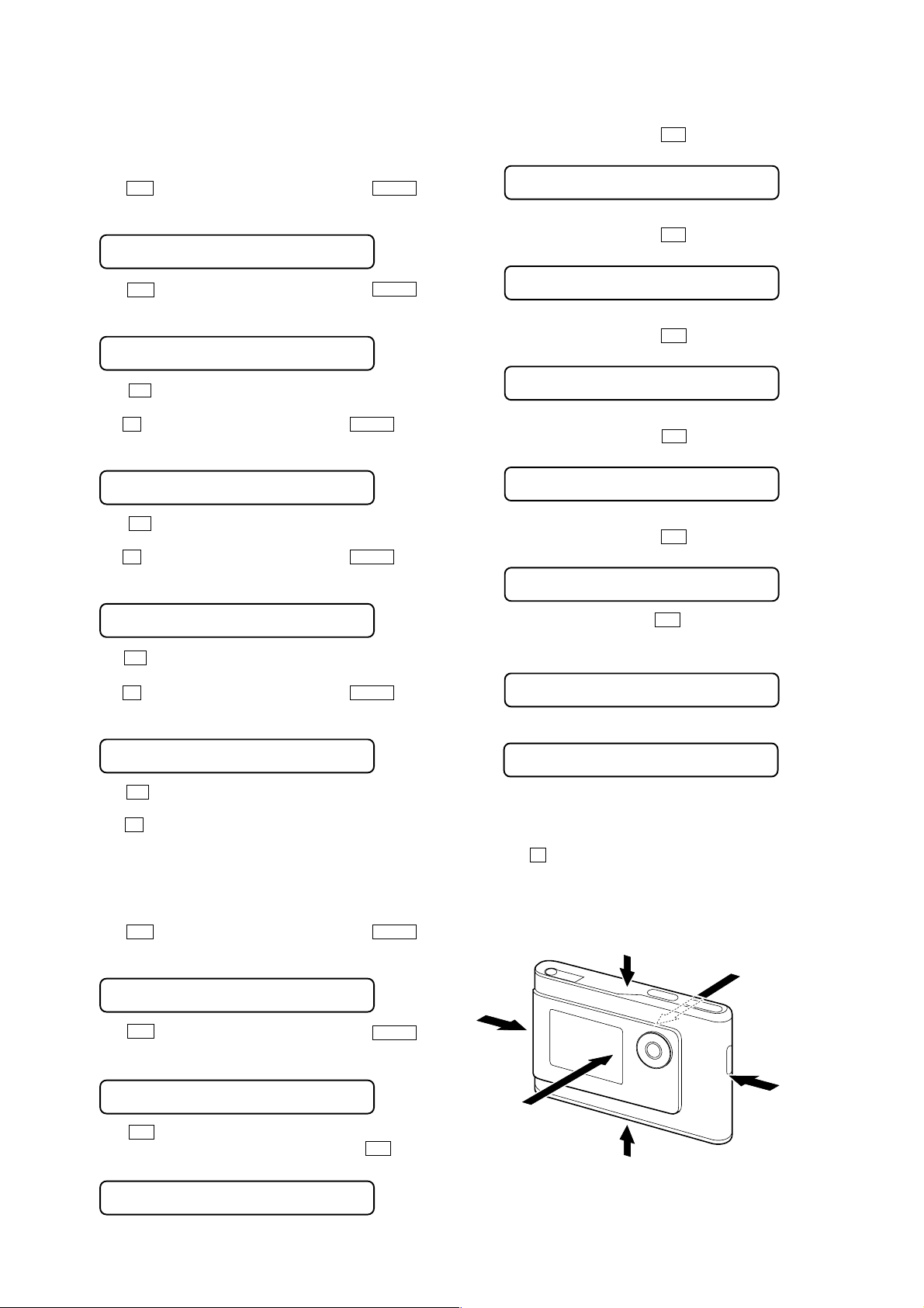
5. “–X” is displayed. Main unit is fixed so that 2 of fig.1 may
become downward and press the u jog.
LCD display of the remote commander
-X
6. “+Y” is displayed. Main unit is fixed so that 3 of fig.1 may
become downward and press the u jog.
LCD display of the remote commander
+Y
7. “–Y” is displayed. Main unit is fixed so that 4 of fig.1 may
become downward and press the u jog.
LCD display of the remote commander
-Y
8. “+Z” is displayed. Main unit is fixed so that 5 of fig.1 may
become downward and press the u jog.
LCD display of the remote commander
+Z
9. “–Z” is displayed. Main unit is fixed so that 6 of fig.1 may
become downward and press the u jog.
LCD display of the remote commander
-Z
LCD 3
8. Press the u jog, monochrome lattice is displayed on the LCD
of main unit.
9. Press the x key to display minor item, and turn the VOL +/– jog
to select the “LCD 4”.
LCD display of the remote commander
LCD 4
10. Press the u jog, monochrome lattice (reverse version of step
8) is displayed on the LCD of main unit.
11. Press the x key , return to minor item selection screen.
5-3-5. G-sensor adjustment
X/Y/Z-axis direction is adjusted.
Adjustment method:
1. Enter the test mode.
2. Press the > jog to display major item, and turn the VOL +/–
jog to select the “OTHERS”.
LCD display of the remote commander
OTHERS
3. Press the > jog to display minor item, and turn the VOL +/–
jog to select the “G CLB”.
LCD display of the remote commander
G CLB
4. Press the u jog, “+X” is displayed. Main unit is fixed so
that 1 of f ig.1 may become downward and press the u jog.
LCD display of the remote commander
10 . “CALIB” is displayed. Press the u jog, G-sensor is adjusted.
Then “FIN”, “DAT NG” or “SEN NG” is displayed automatically.
LCD display of the remote commander
CALIB
r
FIN
FIN : adjusted normally.
DAT NG : The data for performing a calibration is faulty.
SEN NG : The value acquir ed from the G-sensor is f aulty.
11. Press the
2
x key , r eturn to minor item selection screen.
Fig.1 Axis direction of G-sensor adjustment
4
6
1
5
3
14
+X

NW-HD1
5-3-6. G-sensor adjustment check
this mode checks that G-sensor adjustment is performed or not
performed.
Checking method:
1. Enter the test mode.
2. Press the
jog to select the “OTHERS”.
LCD display of the remote commander
> jog to display major item, and turn the VOL +/–
OTHERS
3. Press the > jog to display minor item, and turn the VOL +/–
jog to select the “G CHK”.
LCD display of the remote commander
G CHK
4. Press the u jog, “STAR T” is displayed. Then “OK” or “YET”
is displayed automatically.
LCD display of the remote commander
START
r
OK
5. Press the x key , retur n to minor item selection screen.
5-3-7. Hard disk drive format
This mode is used when performing the format of hard disk drive.
Checking method:
1. Enter the test mode.
2. Press the > jog to display major item, and turn the VOL +/–
jog to select the “OTHERS”.
LCD display of the remote commander
OTHERS
3. Press the > jog to display minor item, and turn the VOL +/–
jog to select the “SC RD1”
LCD display of the remote commander
SC RD1
4. Press the u jog, “READY?” is displayed .
LCD display of the remote commander
READY?
5. Press the u jog, “READ” is displayed and first 1/3 sector of
hard disk drive is read. This operation takes about 50 minutes.
Then the number of error sector is displayed automatically.
LCD display of the remote commander
READ
r
******
******
6. Press the x key to display minor item, and turn the VOL +/– jog
to select the “SC RD2”
LCD display of the remote commander
: number of error sector
SC RD2
7. Press the u jog, “READY?” is displayed .
LCD display of the remote commander
READY?
8. Press the u jog, “READ” is displayed and last 2/3 sector of
hard disk drive is read. This operation takes about 100 minutes.
Then the number of error sector is displayed automatically.
LCD display of the remote commander
Press the x key when canceling.
5-3-10. Language setting
Setting the language.
Checking method:
1. Enter the test mode.
2. Press the
jog to select the “OTHERS”.
LCD display of the remote commander
> jog to display major item, and turn the VOL +/–
OTHERS
3. Press the
jog to select the “LANG”.
LCD display of the remote commander
> jog to display minor item, and turn the VOL +/–
LANG
4. Press the u jog. Press the [DISPLAY] key, language (JAP/
ENG/FRE/GER/ITA/SPA) is selected.
Press the u jog, distination is entered.
Press the x key when canceling.
5-3-11. Sound pressure regulation setting
Setting the sound pressure regulation.
Checking method:
1. Enter the test mode.
2. Press the > jog to display major item, and turn the VOL +/–
jog to select the “OTHERS”.
LCD display of the remote commander
OTHERS
3. Press the > jog to display minor item, and turn the VOL +/–
jog to select the “SP SET”.
LCD display of the remote commander
SP SET
5. Press the x key, return to minor item selection screen.
5-3-13. SDRAM check
This mode is used for the check of SDRAM.
Checking method:
1. Enter the test mode.
2. Press the
jog to select the “OTHERS”.
LCD display of the remote commander
> jog to display major item, and turn the VOL +/–
OTHERS
3. Press the
jog to select the “RAMCHK”.
LCD display of the remote commander
> jog to display minor item, and turn the VOL +/–
RAMCHK
4. Press the u jog, “STAR T” is displayed and SDRAM is checked.
This operation takes about 20 seconds. After check ed, “OK” or
“NG” is displayed automatically.
LCD display of the remote commander
START
r
OK
5. Press the x key, return to minor item selection screen.
NW-HD1
3. Press the > jog to display minor item, and turn the VOL +/–
jog to select the “FORMAT”.
LCD display of the remote commander
FORMAT
4. Press the u jog, “START” is displayed and format of hard
disk drive is performed. After performing format, “OK” or “NG”
is displayed automatically.
LCD display of the remote commander
START
r
OK
5. Press the x key , retur n to minor item selection screen.
5-3-8. Hard disk drive all sector read
All sector of hard disk drive is read.
Checking method:
1. Enter the test mode.
2. Press the
jog to select the “OTHERS”.
LCD display of the remote commander
> jog to display major item, and turn the VOL +/–
OTHERS
READ
r
******
******
9. Press the x key, retur n to minor item selection screen.
5-3-9. Destination setting
Setting the destination.
Checking method:
1. Enter the test mode.
2. Press the
jog to select the “OTHERS”.
LCD display of the remote commander
: number of error sector
> jog to display major item, and turn the VOL +/–
OTHERS
3. Press the > jog to display minor item, and turn the VOL +/–
jog to select the “DEST”.
LCD display of the remote commander
DEST
4. Press the u jog. Press the [DISPLAY] key, destination (J1/
U2/CEX/CEK) is selected.
Press the u jog, destination is entered.
4. Press the u jog. Press the [DISPLAY] key, sound pressure
regulation ON/OFF is selected and press the u jog, sound
pressure regulation ON/OFF is entered.
Press the x key when canceling.
5-3-12. Factory setting
Factory setting is performed.
Checking method:
1. Enter the test mode.
2. Press the
jog to select the “OTHERS”.
> jog to display major item, and turn the VOL +/–
LCD display of the remote commander
OTHERS
3. Press the > jog to display minor item, and turn the VOL +/–
jog to select the “SHIP”.
LCD display of the remote commander
SHIP
4. Press the u jog , factory setting is performed. After the setting,
“FIN” is displayed.
LCD display of the remote commander
FIN
1515
 Loading...