

Sony NWE-8-P Service manual
NW-E8P
SERVICE MANUAL
Ver 1.0 2001.10
SPECIFICATIONS
Recording time
Approx. 60 min. (132kbps)
Approx. 80 min. (105kbps)
Approx. 120 min. (66kbps)
Sampling frequency response
44.1kHz
Recording format
ATRAC3
Frequency response
20 to 20,000 Hz (single signal measurement)
Signal-to-noise ratio (S/N)
More than 80dB (excluding 66 kbps)
Dynamic range
More than 85dB (excluding 66 kbps)
Operating temperature
5°C to 35°C (-41°F to 95°F)
Power source
LR03 (Size AAA) alkaline battery
AEP Model
E Model
Battery life
Approx. 7 hours
Mass (approx.)
90g (3.2 oz) (battery included)
Memory capacity
64MB (including the system software: 60.6MB
available)
Supplied accessories
LR03 (Size AAA) alkaline battery (1)
Attachments (1 for left, 1 for right)
Dedicated USB cable (1)
Carrying pouch (1)
CD-ROM (OpenMG Jukebox installation disc) (1)
NW-E8P Operating Instructions (1)
OpenMG Jukebox Operating Instructions (1)
Design and specifications are subject to change without notice.
9-873-342-01
2001J0200-1
© 2001.10
NETWORK WALKMAN
Sony Corporation
Personal Audio Company
Published by Sony Engineering Corporation

NW-E8P
TABLE OF CONTENTS
Specifications ............................................................................... 1
1. SERVICING NOTE ..........................................................2
2. GENERAL .......................................................................... 3
3. DISASSEMBLY
3-1. Driver ASSY (SP2), Arm Lid (R), Holder Lid (R) ......... 6
3-2. Main Board, Power Board, LCD Unit ............................6
3-3. Driver ASSY (SP1), Arm Lid (L), Holder Lid (L) ......... 7
4. TEST MODE...................................................................... 8
5. DIAGRAMS
5-1. Block Diagrams ............................................................10
5-2. Printed Wiring Boards (Main Section) ......................... 11
5-3. Schematic Diagram (Main Section (1/2)) ..................... 12
5-4. Schematic Diagram (Main Section (2/2)) ..................... 13
5-5. Printed Wiring Boards (Power Section)........................ 14
5-6. Schematic Diagram (Power Section) ............................ 15
6. EXPLODED VIEW
6-1. L-CH Section ................................................................ 17
6-2. R-CH Section ................................................................ 18
7. ELECTRICAL PARTS LIST ....................................... 19
SECTION 1
SERVICING NOTE
z
UNLEADED SOLDER
Boards requiring use of unleaded solder are printed with the
lead-free mark (LF) indicating the solder contains no lead.
(Caution: Some printed circuit boards may not come printed
with the lead free mark due to their particular size.)
: LEAD FREE MARK
Unleaded solder has the following characteristics.
• Unleaded solder melts at a temperature about 40°C higher
than ordinary solder.
Ordinary soldering irons can be used but the iron tip has to
be applied to the solder joint for a slightly longer time.
Soldering irons using a temperature regulator should be set
to about 350°C.
Caution: The printed pattern (copper foil) may peel away if
the heated tip is applied for too long, so be careful!
• Strong viscosity
Unleaded solder is more viscous (sticky, less prone to
flow) than ordinary solder so use caution not to let solder
bridges occur such as on IC pins, etc.
• Usable with ordinary solder
It is best to use only unleaded solder but unleaded solder
may also be added to ordinary solder.
Flexible Circuit Board Repairing
• Keep the temperature of the soldering iron around 270°C during
repairing.
• Do not touch the soldering iron on the same conductor of the
circuit board (within 3 times).
• Be careful not to apply force on the conductor when soldering or
unsoldering.
Notes on chip component replacement
• Never reuse a disconnected chip component.
• Notice that the minus side of a tantalum capacitor may be damaged by heat.
• Replacement of CXD9644GG (IC710) used in the set requires a special
tool.
z
USABLE FORMAT
Use ISO9660 Level 1 format.
2
SECTION 2
GENERAL
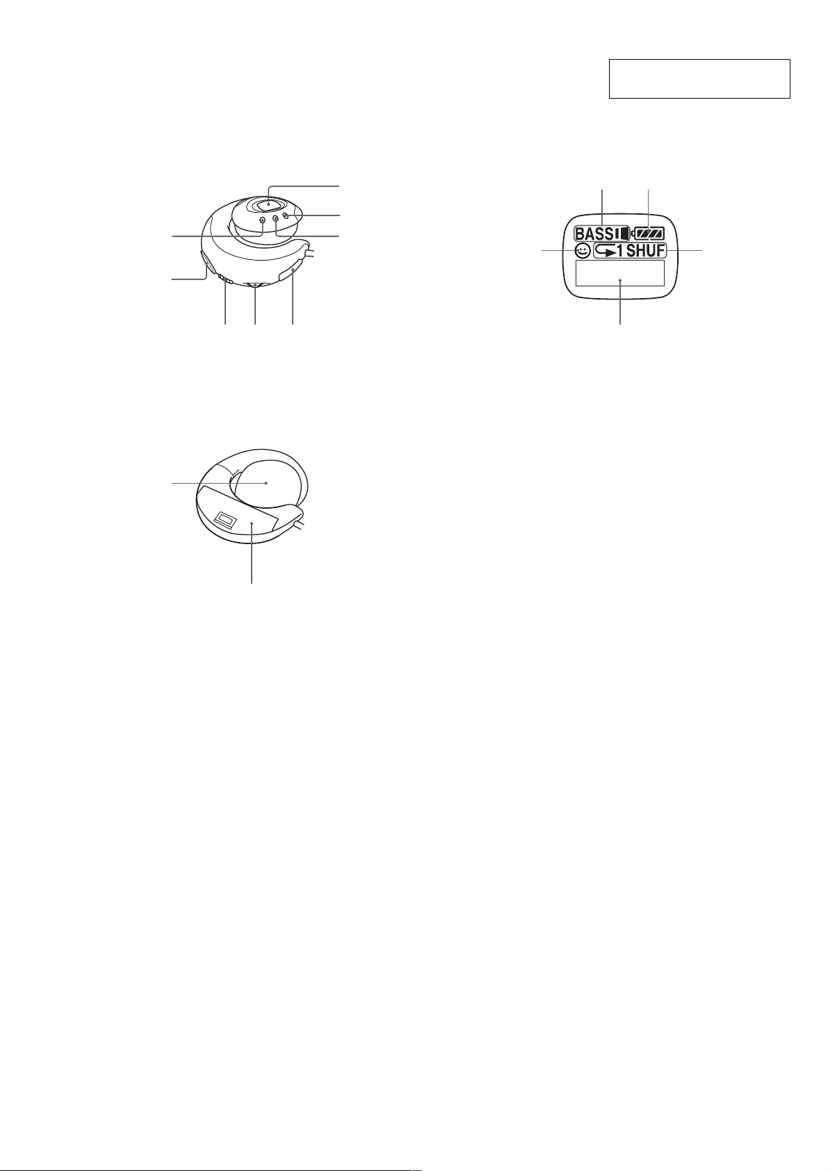
LOCATION AND FUNCTION OF CONTROLS
(front of the right player) Display
NW-E8P
This section is extracted from
instruction manual.
1
2
(rear of the left player)
9
34 5
6
7
8
2
1
1 AVLS indication
2 MEGA BASS indication
3 Battery remain indication
4 Play mode indication
5 T ext/graphic information display
3
5
4
0
1 DISPLAY button
2 VOLUME+/– button
3 HOLD switch
4 Jog lever
5 Dedicated USB jack
6 Display
7 MEGA BASS/AVLS button
8 P.MODE button
9 Ear pad
0 Battery compartment
3
NW-E8P
Basic Operations
Transferring songs from the computer to
Network Walkman (Check-out)
In order to check out digital audio files from your computer, first you must install the supplied
OpenMG Jukebox software and then import digital audio files to OpenMG Jukebox.
For details, refer to the OpenMG Jukebox operating Instructions.
1
Connect Network Walkman to your computer
Connect the narrow connector of the supplied dedicated USB cable into the dedicated USB jack on
Network Walkman, then the wide connector to the USB jack of your computer.
“CONNECT” appears in the display.
to the dedicated
USB jack
Dedicated USB cable (supplied)
Notes
• Do not connect more than two USB devices (player) to your computer. Normal operation will not be
guaranteed.
• If you use this player with a USB hub or a USB extension cable normal operation is not guaranteed.
• A malfunction may occur depending on the USB devices connected at any one time.
• Be sure to insert a fresh Alkaline battery into the unit. If the battery is not inserted, or battery power is
exhausted, the unit will not be identified by the computer.
• When connecting Network Walkman to your computer for the first time, the USB driver Installer window
appears. Please follow the instructions in the Installer window.
• Connect Network Walkman only as necessary. Disconnect the dedicated USB cable when not needed.
to the USB jack
Listening to music with Network
Walkman
Please insert the battery before use (see page 7).
Note
When using Network Walkman, be sure to disconnect it from the computer.
1 Putting the player on your ears
The attaching
part of this player
would be open
(be apart)
flexibly.
1 Pinch the center of
the player with your
thumb and middle
finger, and then open
the attaching part
with your forefinger.
2 Hook the cured part
around the back of your
ear and twist it to the
earlobe direction to sit it
on your ear. If your hair
hangs over your ear,
please push back your
hair before attaching it.
k
Notes
• Please remove earrings.
• If you wear the glasses, remove your glasses before
putting on this player and put them on again.
• Be sure not to open the attaching part more than
2 cm. Otherwise, this player may deform and
2cm
might not sit on your ears comfortably. Note that
if you press the player to opposite side, it also
may deform.
Hook the
edge of the
attaching part
to the back of
k
your ear and
twist it.
Basic Operations
2
Transfer the music file to Network Walkman (Check-out)
For details on how to operate, refer to the OpenMG Jukebox Operating Instructions.
Tip
To transfer the song back to the computer (check-in), refer to the OpenMG Jukebox software instruction manual
or the online help.
8
Listening to music with Network Walkman (continued)
2
Release the HOLD function
If the HOLD switch is in the arrow direction ( the yellow mark is
visible), slide it to the opposite direction to release the HOLD function.
3
Start playback
2 VOLUME
+/– button to adjust
the volume.
HOLD switch
1 Press the Jog lever
Bx. Playback starts.
When playback ends,
the playback
automatically stops
(in the case the player
is set to REPEAT OFF).
If playback does not start
Make sure the HOLD function is released.
To stop playback
Press the Jog lever Bx.
Tip
If you do not operate the player for 3 seconds while in stop mode, the display automatically turns off.
3 Adjust the position of
the player to fix it
comfortably.
If you cannot attach the player to your ear comfortably
Confirm the position of the player with a mirror. In the correct position, your ears should appear as
illustrated. if your ears are small and not visible as shown, use the supplied attachments (see page 15).
To remove the player from your ears
Twist the player to the opposite direction when attaching it, and remove it.
H
O
L
D
F
F
On other operations
Jog lever
FF direction
REW direction
To
Go to the beginning
of the next track
Go to the beginning
of succeeding
1)
tracks
Go to the beginning
of the current track
Go to previous
1)
tracks
Go forward
Go backward
Operation of
the Jog lever
Press in the FF direction
once.
Press in the FF direction
repeatedly.
Press in the REW direction
once.
Press in the REW direction
repeatedly.
2)
During playback, press in
the FF direction and hold .
2)
During playback, press in
the REW direction and
hold.
1)
While in stop mode, press the Jog lever in the FF
direction and hold, you can go to the beginning of
the next track and succeeding tracks continuously.
While in stop mode press the Jog lever in the REW
direction and hold, you can go to the beginning of
the current track and previous tracks continuously.
2)
If you press and hold in the FF or REW direction
for more than 5 seconds, the search speed
increases.
continued
9
Basic Operations
continued
10
11
4
NW-E8P
m
Listening to music with Network Walkman (continued)
On the display
3
2
1
1 AVLS indication (page 13)
The indication lights up while the AVLS
function is activated.
2 MEGA BASS indication (page 13)
The indication lights up while the MEGA
BASS function is activated.
3 Battery remain indication (page 7)
The remaining battery power is
displayed.
4 Play mode indication (page 14)
The selected play mode is displayed.
Play status/Track number display
5
The following information is displayed
according to the display mode.
Play status Play status
Play status
During playback:
displayed alternately.
In stop mode:
While locating tracks: > or
. is displayed.
While searching a point in a track:
M or m is displayed.
When you play back songs for
more than 15 seconds, a wave
pattern is displayed.
5
or is
is displayed.
12
4
Track
number
Volume
indication
(Displayed
numerically.
Max. volume is
31)
Changing the display mode
Press the DISPLAY button while the wave is
displayed during playback and the track
number is displayed.
About the backlight
If you perform the following operation, the
backlight lights up for a few seconds.
• Press the buttons (VOLUME+/--, DISPLAY,
P.MODE, MEGABASS/AVLS)
• Operate the Jog lever
Note
In a bright place, the backlight may not be
apparent.
DISPLAY
button
Track
number
Attaching the attachments
If your ears are small and you cannot attach the player correctly, use the supplied attachments.
Example for left ear
1
2 Turn the attachment to click into place.
To remove the attachment
1 Pull the edge of the attachment in
For left ear For right ear
LR
Engage the pin in the slot as shown, and
insert the attachment.
the direction of the arrow.
pin
3 Press the point shown by the arrow to
secure it.
2 Lift its edge and turn it in the
direction of the arrow to remove it.
Advanced Operations
15
5
NW-E8P
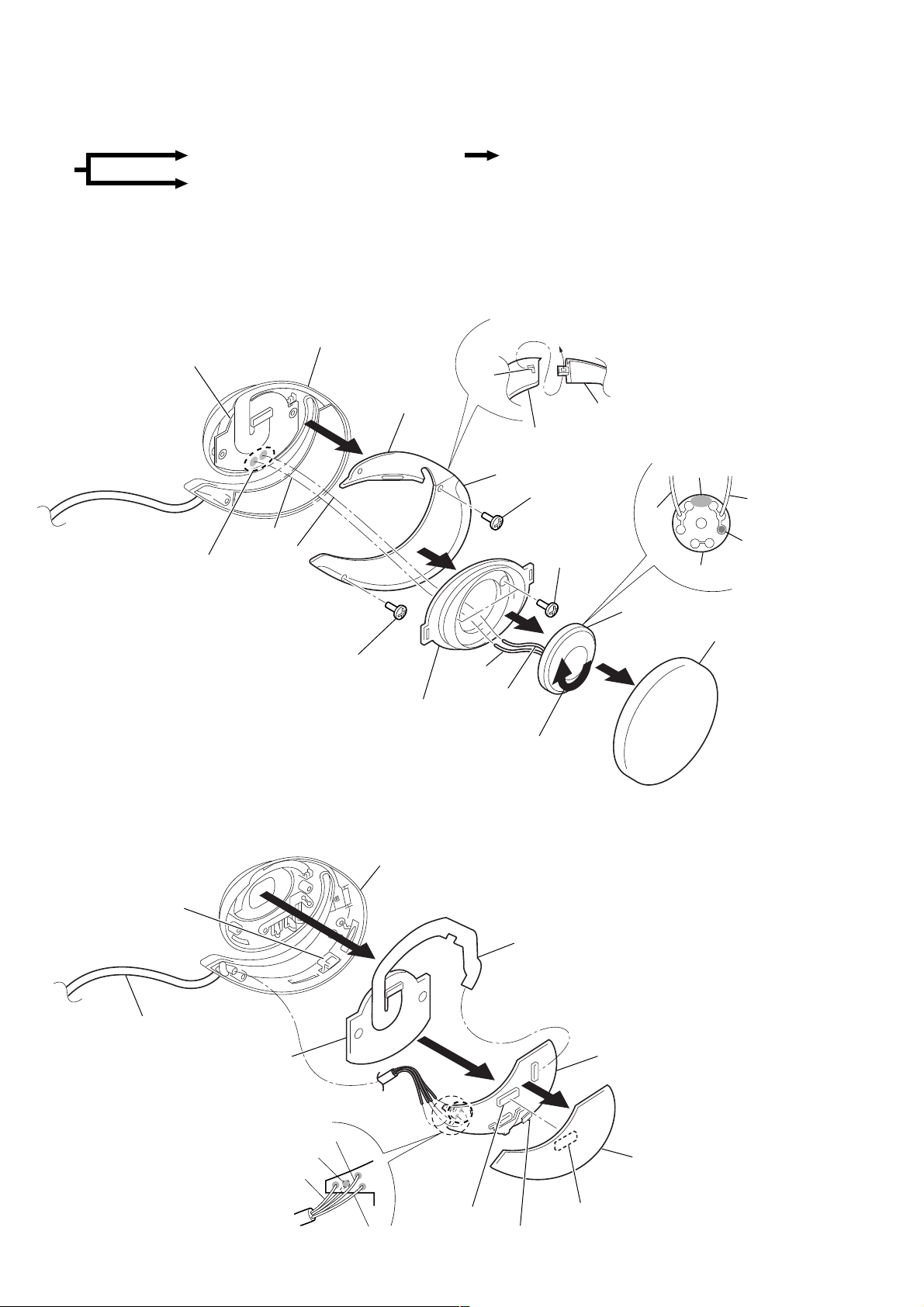
SECTION 3
DISASSEMBLY
z
The equipment can be removed using the following procedure.
<R-CH section>
Set
<L-CH section>
Note : Follow the disassembly procedure in the numerical order given.
<R-CH section>
3-1. DRIVER ASSY (SP2), ARM LID (R), HOLDER LID (R)
Driver ASSY (SP2), Arm lid (R), Holder lid (R)
Driver ASSY (SP1), Arm lid (L), Holder lid (L)
Holder (R) ASSY
LCD unit
Main board, Power board, LCD unit
• Installation of holder lid (R)
and arm lid (R)
Claw
8
Red
4
Remove solder
(2 places)
Black
7
Screw
B1.7x5
<R-CH section>
3-2. MAIN BOARD, POWER BOARD, LCD UNIT
Arm lid (R)
Front plate
Holder lid (R) (rear side)
Holder lid (R)
7
6
3
Red
Black
2
Turn to clockwise
to release lock.
Arm lid (R) (rear side)
Screw B1.7x5
5
Screws
B1.7x5
• Connection of driver ASSY
Glue
Red
Black
Marking (red)
Driver ASSY
Driver ASSY (SP2)
Ear pad
1
Holder (R) ASSY
Knob (HOLD)
Cord (4 core)
LCD unit
4
Remove solder
(4 places)
Red/clear (rear side)
Green/clear
5
3
Red
CN704
Green
2
LCD flexible board
(Power board: CN705)
1
CN702
HOLD switch
(S704)
Power board
z
Caution during assembly
Align HOLD switch (S704) with
the position of knob (HOLD).
Main board
6
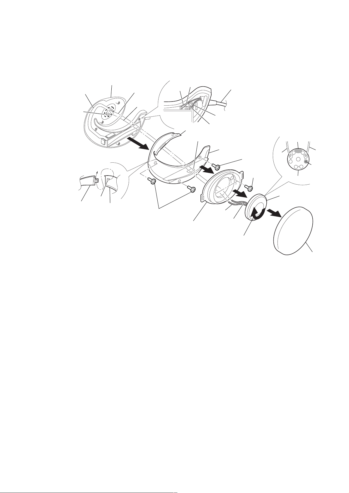
<L-CH section>
Y
3-3. DRIVER ASSY (SP1), ARM LID (L), HOLDER LID (L)
NW-E8P
MDD flexible board
4
Remove solder
(2 places)
Note:
When soldering,
paying attention as
holder (L) doesn’t
transform it by a heat.
• Installation of holder lid (L)
and arm lid (L)
Lid (L), arm
(rear side)
Holder (L) ASSY
Claw
Holder lid (L)
Red
Black
9
8
Screws B1.7x5
• Wiring of cord (4 core)
Red
Green
Arm lid (L)
Front plate
Green/clear
7
Open the battery lid.
6
Cord (4 core)
Red/clear
Holder lid (L)
3
Black
Red
2
Turn to clockwise
to release lock.
8
Screw
B1.7x5
5
Screws
B1.7x5
• Connection of driver ASS
Glue
Black
Driver ASSY
Driver ASSY (SP1)
1
Red
Marking
(red)
Ear pad
7

NW-E8P
)
C
7
7
SECTION 4
TEST MODE
Setting the Test Mode
To enter the test mode, two methods are available :
1. Entering method with key input.
Turn the HOLD switch to ON. While holding down the Bx key, press the following keys in the following order :
VOLUME + t VOLUME – t VOLUME – t VOLUME + t VOLUME – t MEGA BASS t MEGA BASS t DISPLAY
Note : Push each key for less than 3 seconds.
2. Entering method by shorting the test point.
Solder brige the test point SL701 (TEST) on the main board and turn on the power.
MAIN BOARD (SIDE B)
TP3
Test mode
Short : Test mode
( )
Open : Normal mode
P701
D781
R764
TP701
R705
R769
R703
R767
R783
TP702
TP703
(TEST)
1
3
2
5
4
C704
IC820
C703
JC722
X701
5
1
2
1
R7
R77R7
4
3
CN701
USB
CONNECTOR
1-681-242-
5
(13)
13
Releasing the TEST mode
1. When test mode was entered with key input, turn off the power supply.
2. When test mode was entered by shorting the test point, turn off the power supply and open the solder brige of SL701 (TEST) on the main
board.
Connection
regulated
Set
Battery terminal
CN701
(USB Connector)
DC power supply
Connecting cable
supplied with the set
USB Connector
(1-784-009-11 or 1-779-676-11
regulated
DC power supply
4
1
Configuration of Test Mode
The test mode has the configuration given below.
Bx : Play/stop key
(+) : VOLUME + key
(–) : VOLUME – key
LCD
Check
Bx
(+)
(–)
Flash memory
bad block
check
(+)
(–)
Destination
setting
(+)
(–)
Contrast
adjustment
(+)
Ver. /
destination
display
Bx
All display
lit
Bx
All display
off
Bx
Supply 0.9V DC to battery
terminal and press (–) key.
(–)
Low voltage
check
Supply 1.24V DC to battery
terminal and 7V DC to USB
connector and press (+) key.
High DC
detection
(–)
check
Supply 1.24V DC to battery
terminal and 4V DC to USB
connector and press (+) key.
Low DC
detection
(–)
check
8
 Loading...