

Sony NP50C3MF01, NP50C4MF01, KE-50MR1 AEP, KE-50MR1 K, KE-50MR1E HK Service Manual
...
PANEL MODULE SERVICE MANUAL
PDP Module Name
FLAT PANEL COLOR TV
KE-50MR1/50MR1E/MR50M1
NP50C3MF01
NP50C4MF01
KE-50MR1 AEP Model
KE-50MR1 K Model
KE-50MR1E HK Model
KE-50MR1E ME Model
KE-MR50M1 CH Model

Contents
1. Confirmation Common Manual ・・・・・・・・・・・・・・・・・・・・・・・ P1~P20
2. Confirmation Manual ・・・・・・・・・・・・・・・・・・・・・・・・・・・・・・ P21~P44
3. Repair Manual ・・・・・・・・・・・・・・・・・・・・・・・・・・・・・・・・・・・・ P45~P63
4.THE PARTS INFORMATION・・・・・・・・・・・・・・・・・・・・・・・・・・・・・ P64~P65

1
PDP (NP series) Confirmation Common
Manual
Ver.1
2
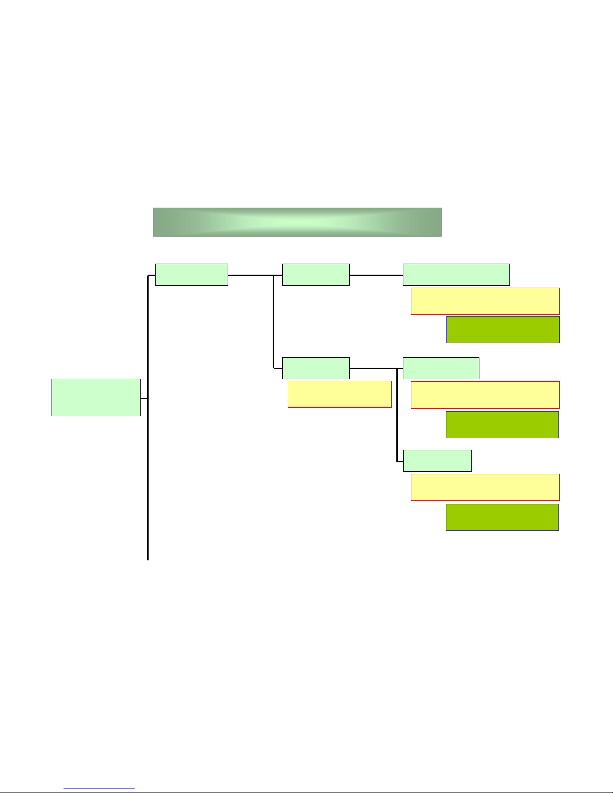
Malfunction
Phenomenon
No Picture Power-off
Power-on
Alarm protection
No Priming
No Signal
When you turn-on the main power,
the LED light-off after few minutes.
Go to Page 8
due to check more details.
The priming does not appear on
screen.
The LED is lighting, but
not appear pictures.
PDP Malfunction Phenomenon
Go to Page 10
due to check more details.
The priming is on screen, but not
appear pictures.
Go to Page 10
due to check more details.
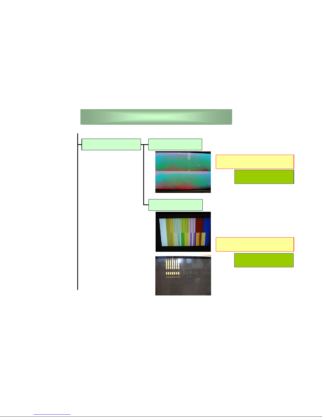
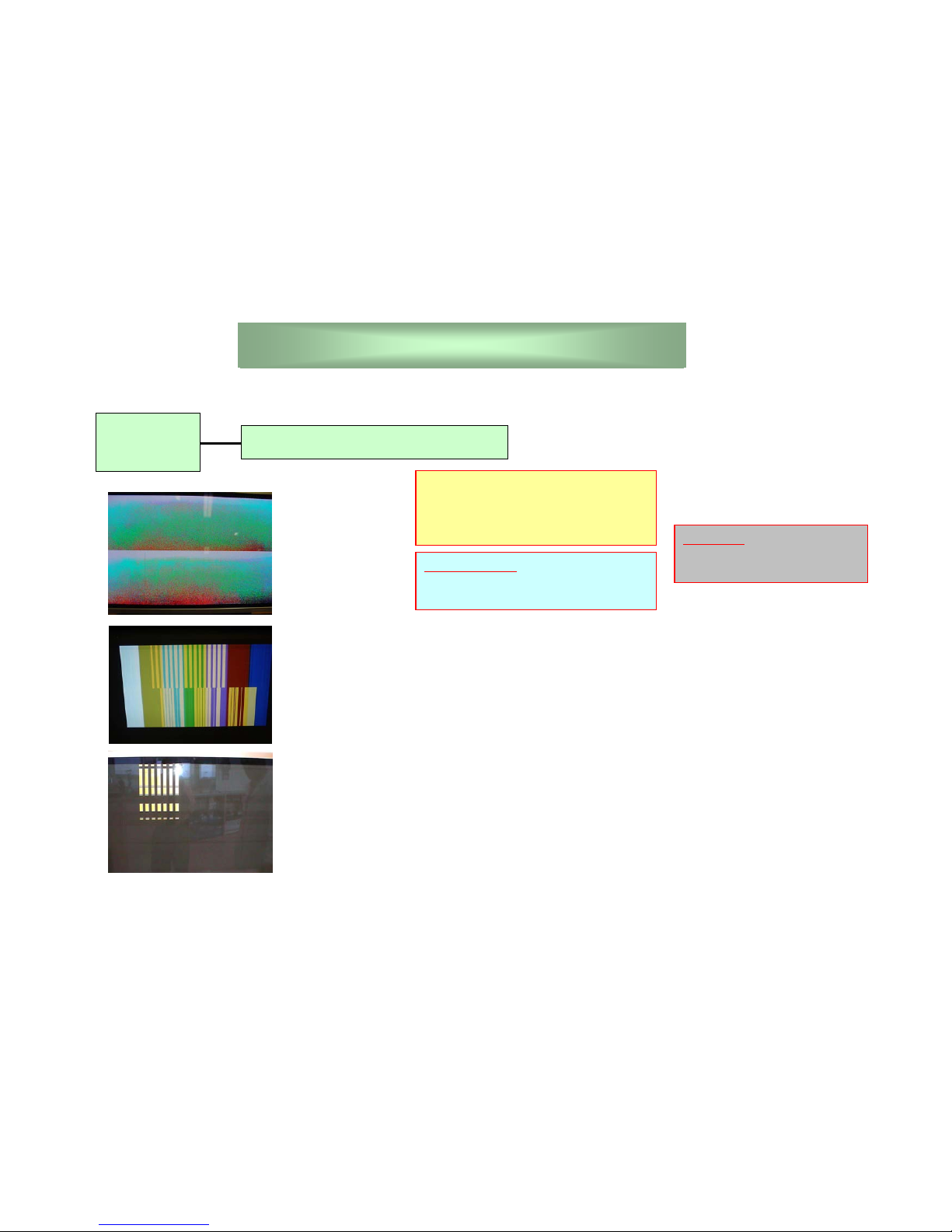
3
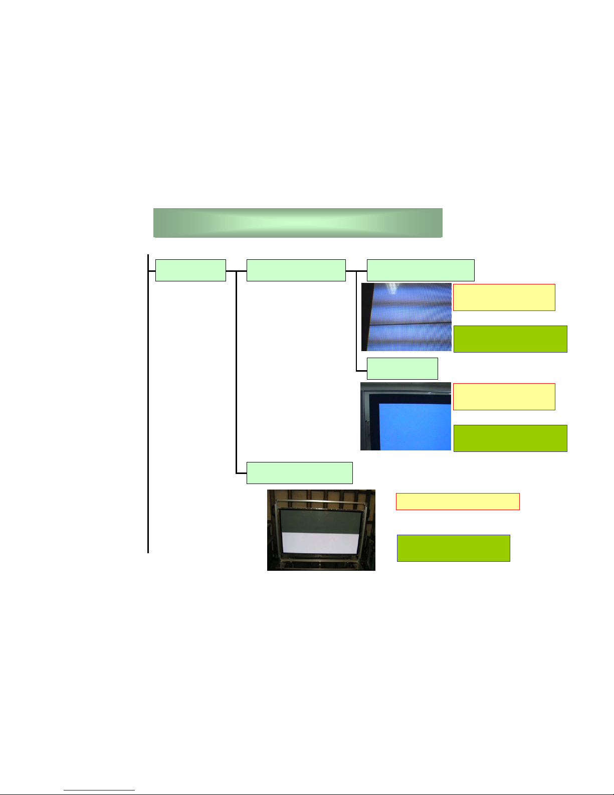
No lighting sell are on screen at
white pattern.
Go to Page 11
due to check more details.
Colorful blocks appear on screen at
color bar pattern.
PDP Malfunction Phenomenon
Go to Page 11
due to check more details.
Abnormal Screen Abnormal Color
Abnormal Block
4
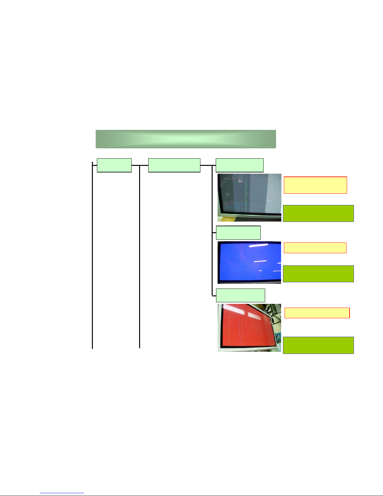
PDP Malfunction Phenomenon
Vertical Vertical Line Single Line
Two Lines
Many Lines
Only one line is always
lighting.
Go to Page 12
due to check more details.
two lines are lighting.
Go to Page 13
due to check more details.
Many lines are lighting.
Go to Page 14
due to check more details.
5
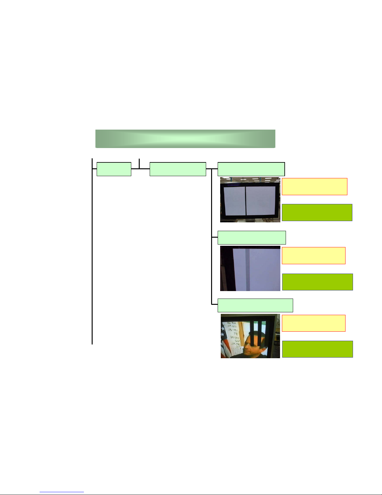
PDP Malfunction Phenomenon
Vertical Vertical Block One Black Block
One Zebra Block
Many Black Blocks
One block is always nolighting by one IC.
Go to Page 15
due to check more details.
Zebra block appears
by one IC.
Go to Page 16
due to check more details.
Many block appear by
one data relay board.
Go to Page 16
due to check more details.
6
PDP Malfunction Phenomenon
Horizontal Horizontal Line
Horizontal Block
One Black Block
One black line appears
on screen.
Go to Page 17
due to check more details.
Two Lines
Two lines appear on
screen.
Go to Page 18
due to check more details.
Half block does not go out.
Go to Page 19
due to check more details.
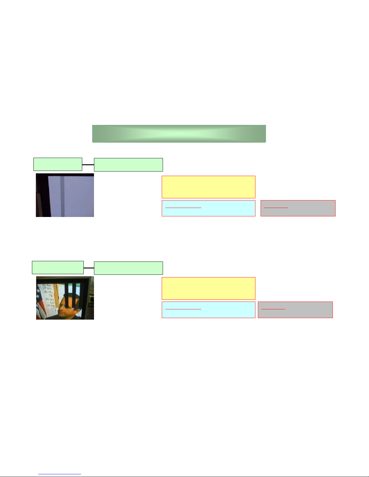
7
Lighting strip
PDP Malfunction Phenomenon
Check our specification .
Screen Defect
Black strip
Check our specification .
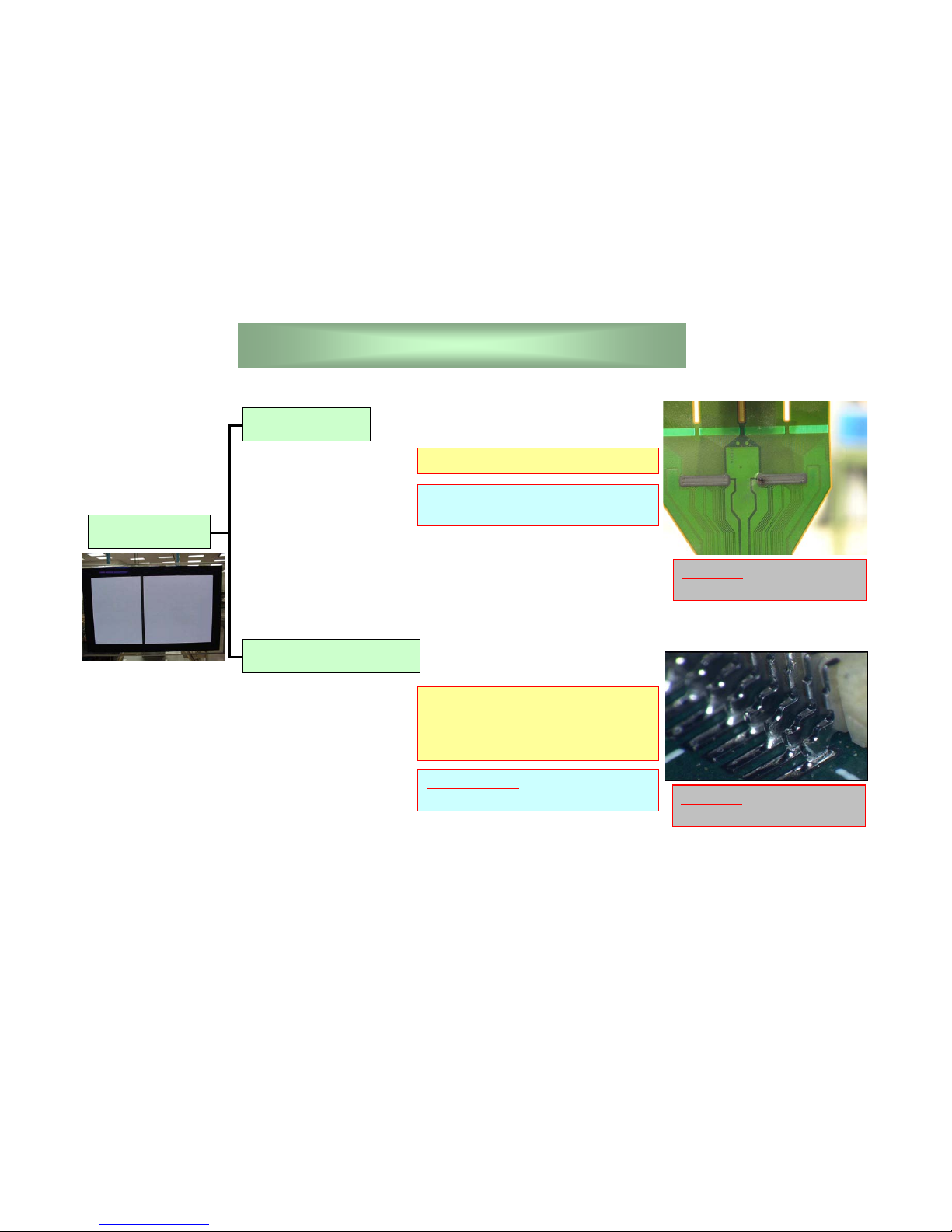
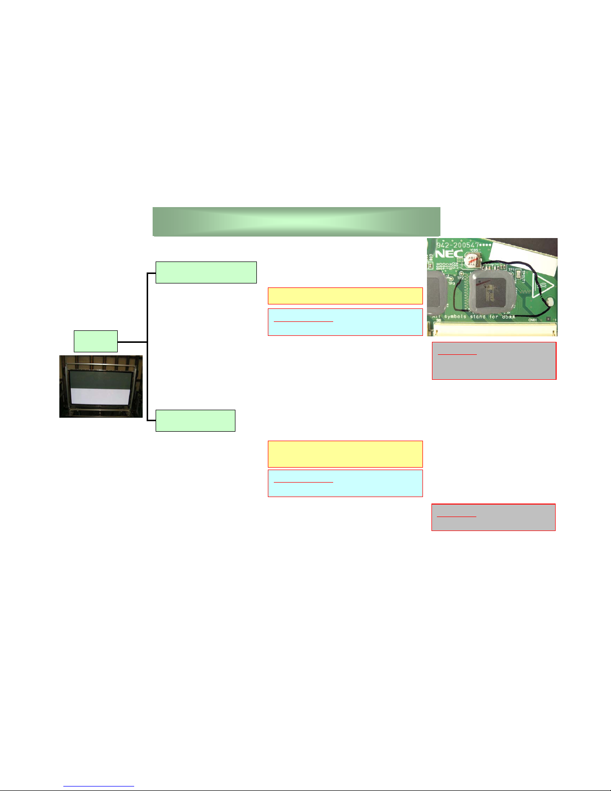
8
Alarm
Protection
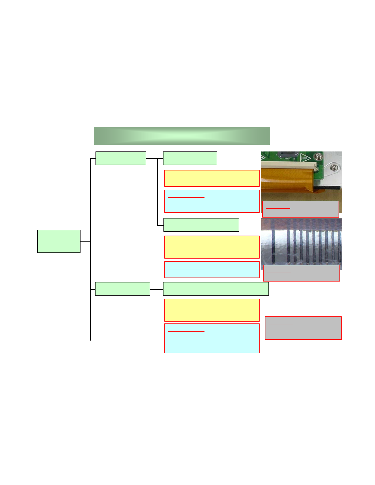
Panel Alarm FPC Opened
No Picture
Panel alarm line go through the edge
of the FPC.
Vs Protection
Panel Grid Opened
High Voltage Circuit Broken
Panel alarm line go through the edge
of panel.
This case is caused by sulfur issue.
Next parts will be broken, Scan
Board, Common Board, High Voltage
Board, Scan Relay Board.
CHECK POINT
FPC cutting at scan side and TCP
side.
CHECK POINT
Panel Grid condition.
CHECK POINT
Fuse on boards, Power HIC,
Between NEGA and POSI on scan
relay board
REWORK
Change the Scan, Common
board and Scan relay board.
REWORK
We can not rework this.
REWORK
We can not rework this.

9
Alarm
Protection
No Picture
In case of shortage between Vd line
and GND in TCP, Vd protection will
be worked.
Vd Protection
5V Protection
TCP Broken
Data Relay Board Broken
Digital Board Broken
CHECK POINT
Shortage between Vd line and GND,
TCP surface
In case of shortage between Vd line
and GND in data relay board, Vd
protection will be worked.
CHECK POINT
Shortage between Vd line and GND
on data relay board.
In case of no supply from supply
board, 5V protection will be worked.
CHECK POINT
Fuse on digital board
REWORK
We can not rework this.
REWORK
Change the data relay board.
REWORK
Change the digital board.
10
No Priming
No Signal
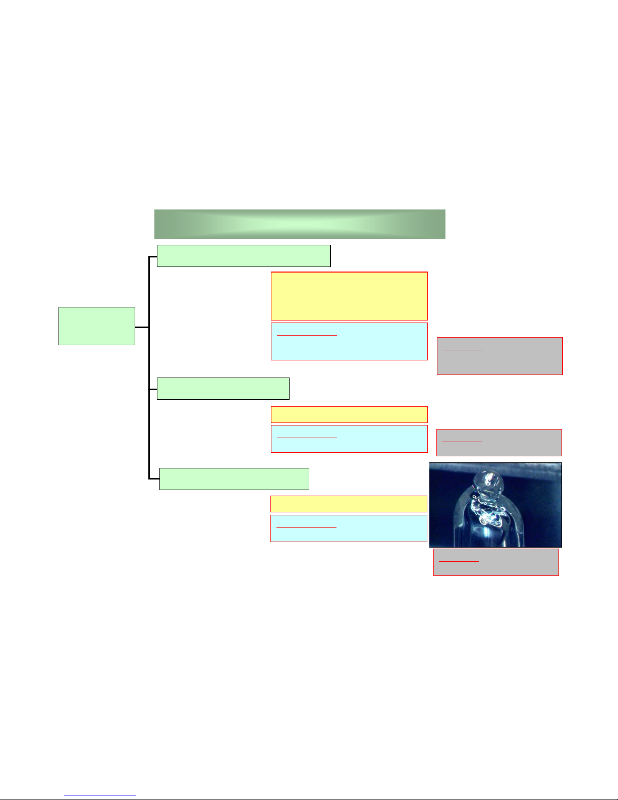
High Voltage Circuit Broken
No Picture
Digital Board Broken
Digital is not working.
CHECK POINT
Fuse on board, Vp, Vbw and Vsw
line of Power HIC.
CHECK POINT
fuse on digital board, LVDS cable
Next parts will be broken, Vp or Vbw
line on Scan Board, Vsw line on
Common Board, (High Voltage
Board).
REWORK
Change the scan or common
board (High voltage board).
REWORK
Change the digital board.
Vacuum Tube Cracking
With big noise.
CHECK POINT
Vacuum tube
REWORK
We can not rework this.
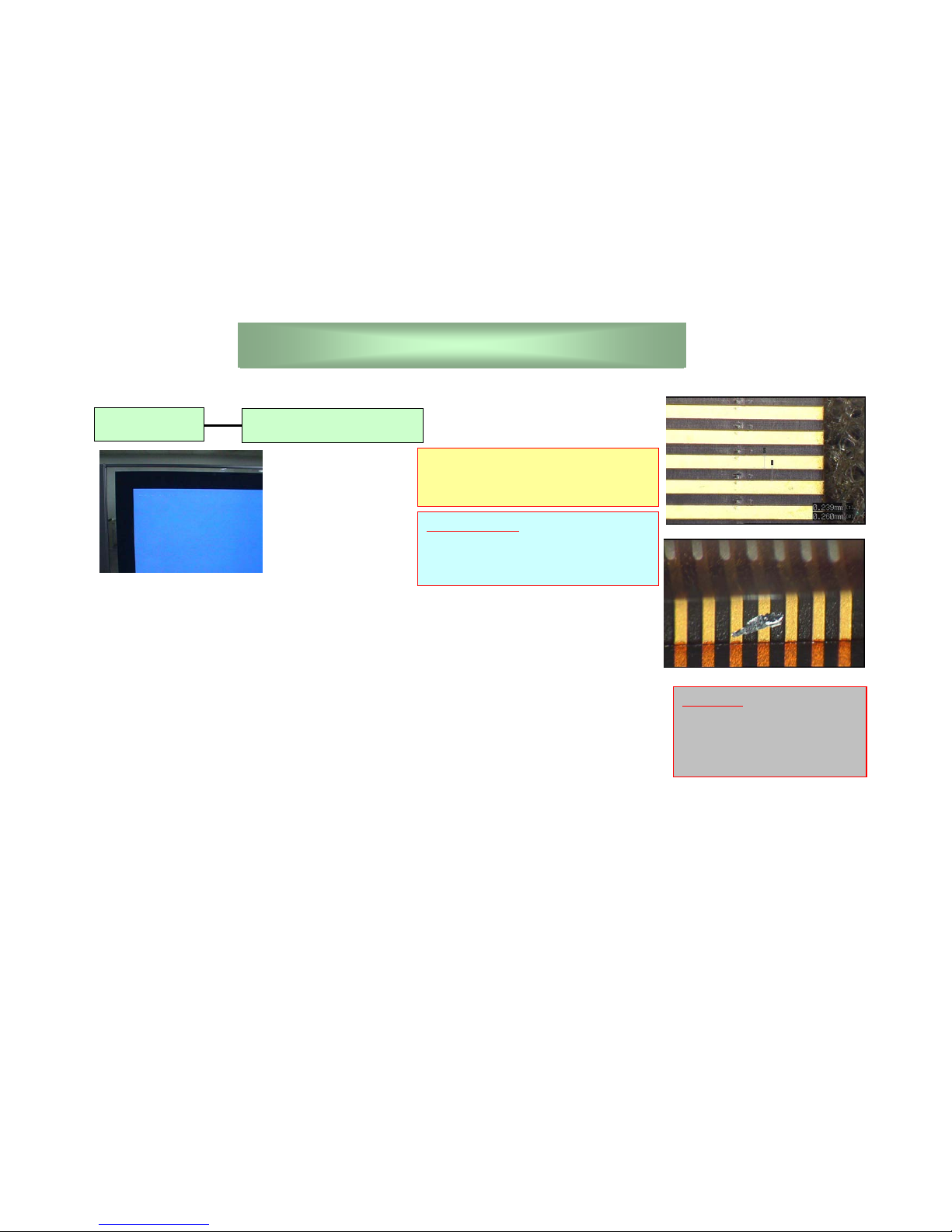
11
No Picture
Abnormal
screen
High Voltage Circuit Broken
CHECK POINT
fuse on board, Vbw or Vsw line on
board.
Next parts will be broken, Vbw line
on Scan Board, Vsw line on
Common Board, (High Voltage
Board).
REWORK
Change the scan or common
board (High voltage board).
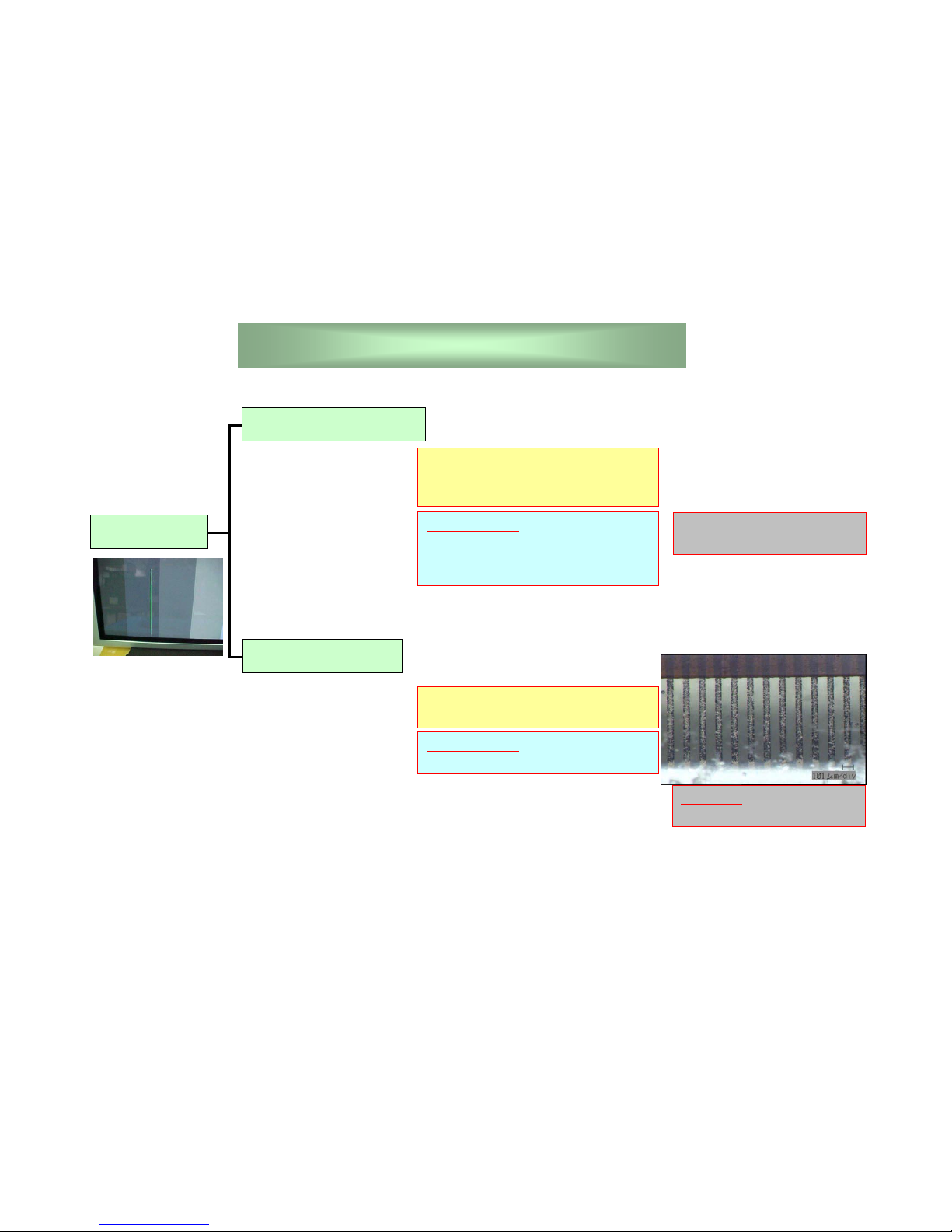
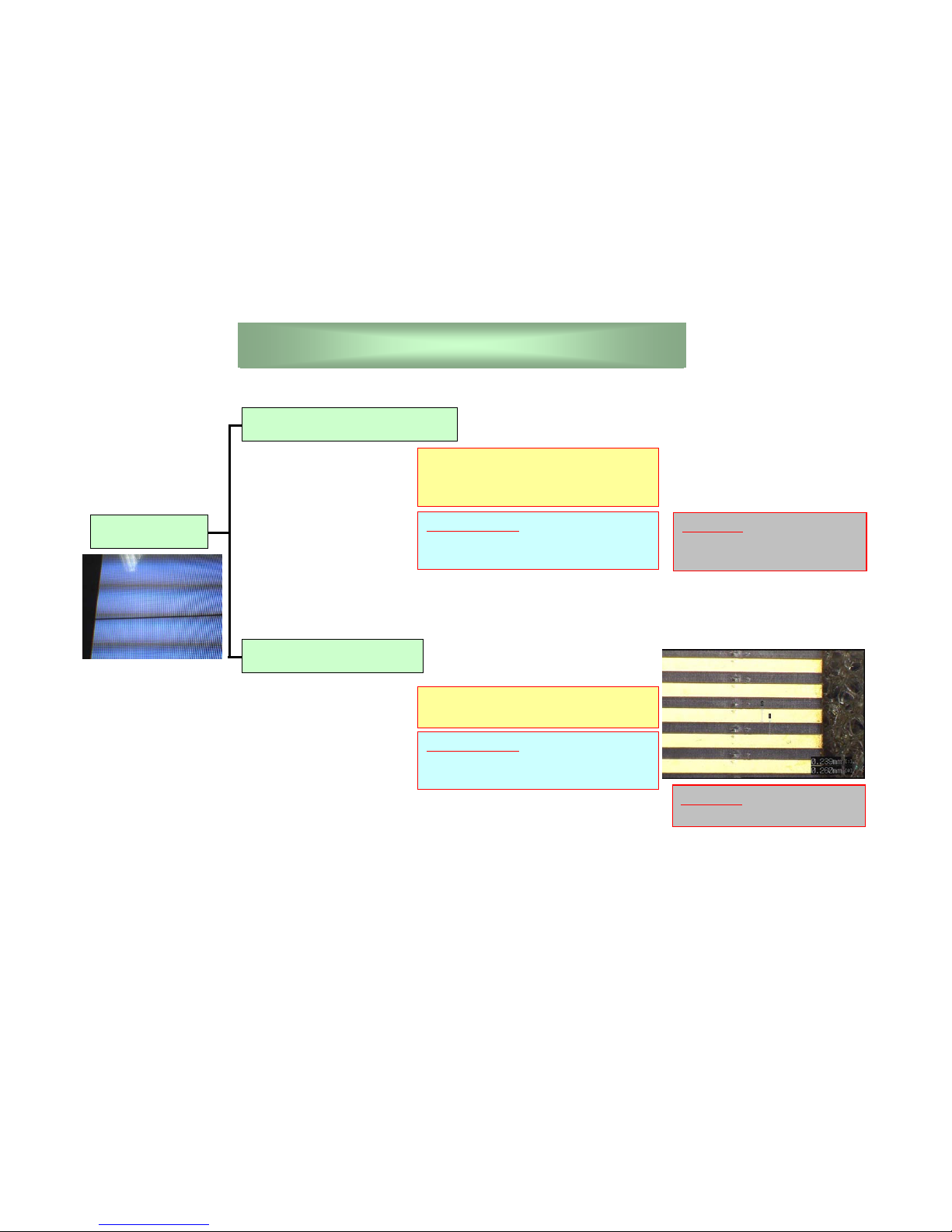
12
Single Line
The output of TCP
Vertical
Data Grid Open
Damaged data grid in panel
EX) Sulfur, scratch
CHECK POINT
One line is no-lighting or lighting at
any pure color signal (red, green
blue and black)
CHECK POINT
The surface condition of panel grid.
The output of TCP is fixed at low
level or high level.
This line is very clear and constant.
REWORK
We can not rework this.
REWORK
We can not rework this.
13
Two Lines
The output of TCP
Vertical
Data Grid Shortage
The grids of panel are shortage due
to foreign material.
CHECK POINT
Two lines are lighting at two colors.
CHECK POINT
The surface condition of panel grid.
The closed outputs of TCP are
Shortage.
REWORK
We can not rework this.
REWORK
We can not rework this.
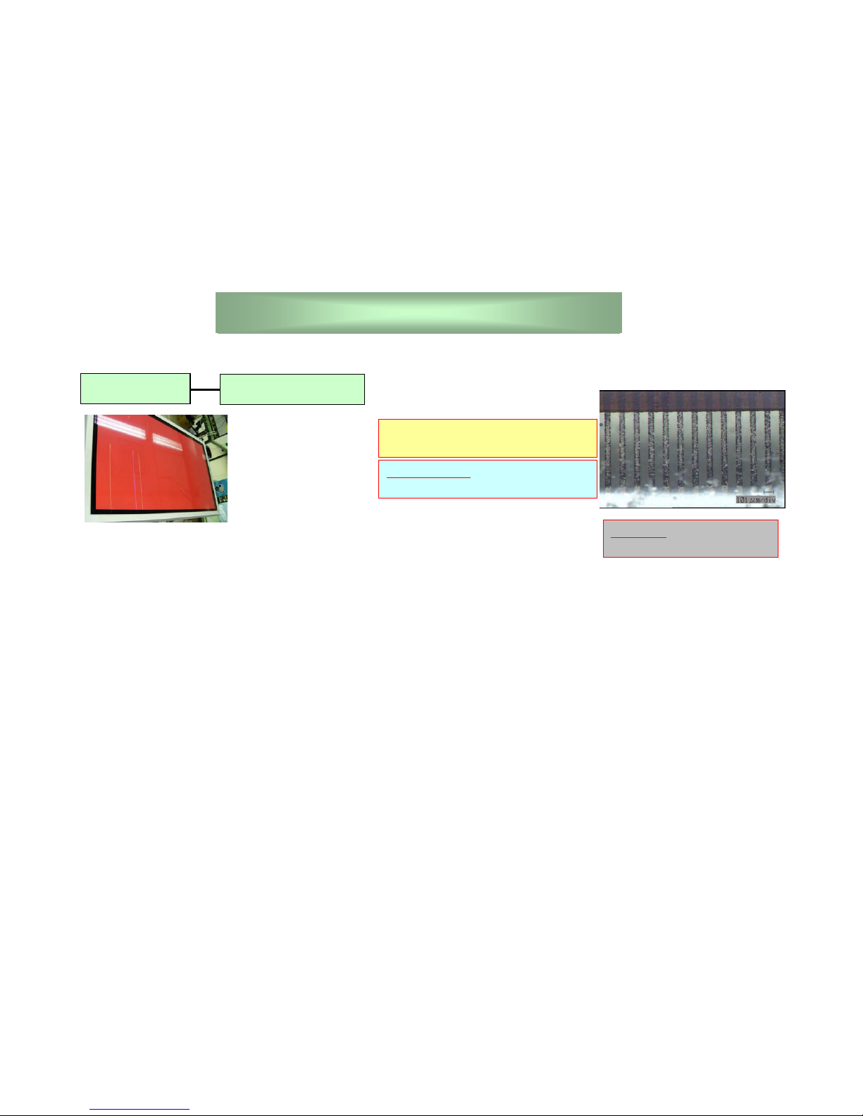
14
Many Lines
Vertical
Data Grid Open
Damaged data grid in panel
EX) Sulfur, scratch
CHECK POINT
The surface condition of panel grid.
REWORK
We can not rework this.
15
Black Block
TCP Broken
Vertical
Data Relay Board
The buffer IC is not working on signal
lines.
The connector on data relay board is
opened by the cracking of solder.
CHECK POINT
The surface of TCP is damaged.
CHECK POINT
Input signal condition.
TCP is not working.
REWORK
We can not rework this.
REWORK
Change the data relay board.
16
Zebra Block
Vertical
Data Relay Board
The lead of the buffer IC or the
connector on data relay board are
shortage by foreign material.
CHECK POINT
Input signal condition.
REWORK
Change the data relay board.
Many Blocks
Data Relay Board
The lead of the buffer IC or the
connector on data relay board are
shortage by foreign material.
CHECK POINT
Input signal condition.
REWORK
Change the data relay board.
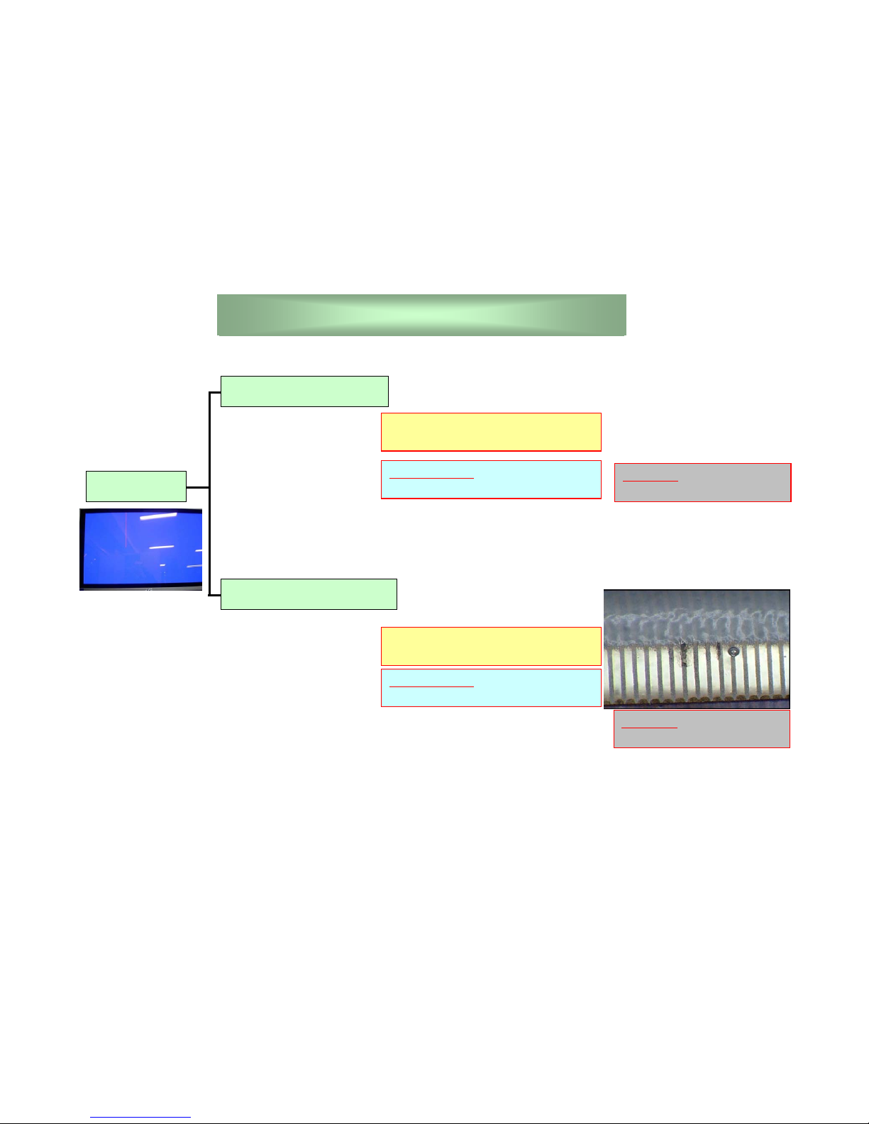
17
Single Line
The output of Scan IC
Horizontal
Scan Relay Board
Mis-contact between FPC and the
connector of scan relay board.
CHECK POINT
One line is no-lighting or lighting at
white signal.
CHECK POINT
The output of scan IC.
Reconnection.
The output of scan IC is fixed at low
level or high level.
This line is very clear and constant.
REWORK
Change the scan relay
board.
REWORK
Reconnect the FPC.
18
Two Lines
Horizontal
Scan Relay Board
CHECK POINT
FPC insert shifting.
Foreign material in connector.
The lead of scan IC.
The output of scan IC are shortage.
This line is not clear and not
constant.
REWORK
Clean in the connector.
Reconnect the FPC.
Change the scan relay
board.
19
Block
Scan IC broken
Horizontal
The output of scan board is not
working.
CHECK POINT
The surface of scan IC.
CHECK POINT
The output of Scan Board.
Scan IC is not working.
REWORK
Change the scan relay
board.
REWORK
Change the scan board.
Scan Board
 Loading...