

Sony NAVITUS RM-NX7000 Software Manual

Features
NAVITUS Design is a software application that lets you edit the RM-NX7000 settings on your PC. NAVITUS Design makes it easy to program
Action lists or set the Zapping function. Furthermore, NAVITUS Design makes it easy to enjoy a wide range of customizing options such as
importing favorite images from a PC and using them as key skins or the Remote Commander's wallpaper.
Programming the Remote Commander is intuitive
NAVITUS Design provides an easy to use GUI (Graphical User Interface) for programming the Remote Commander's hard keys and LCD
functions. You can change, assign, and arrange the functions and look of each key and the entire LCD. It is fast and easy to create custom
screens as well as macro functions by using NAVITUS Design.
Customizing the key skins and the Remote Commander wallpaper is fun and easy
NAVITUS Design makes it possible to select the skin (appearance and color) of each key and the Remote Commander wallpaper from a
wide variety of designs. To truly customize the display, it is possible to import and apply pictures from a PC for button designs and
wallpaper.
Easier editing Action lists
NAVITUS Design allows you to check/edit Action lists programmed for the keys and buttons on a list, which makes it easier to check/edit the
Action list than you do with the Remote Commander.
By connecting the Remote Commander to your PC with the USB cable, you can also check the remote control signals of the Action list on
NAVITUS Design.
Checking the operations of the Remote Commander on your PC (EMULATE mode)
NAVITUS Design provides the "EMULATE" mode, in addition to the EDIT mode for editing the Remote Commander settings. The EMULATE
mode makes it possible to check how the Remote Commander will work when the Remote Commander's key or button is pressed on
NAVITUS Design.
Note
In the EMULATE mode, you can only check the visual aspects of the Remote Commander, like page transitions when a key or button is
pressed, or a key's appearance on the page (assignment, skin, label, etc.). Using NAVITUS Design, you cannot check how AV components
will respond to buttons being pressed on the Remote Commander.
Exchanging data through the USB cable or a Memory Stick media
NAVITUS Design allows you to exchange data between the Remote Commander and your PC through the supplied USB cable or an
optional Memory Stick via the Memory Stick slot. It is possible to upload the Remote Commander settings to NAVITUS Design and change
the settings, or download the NAVITUS Design settings to the Remote Commander.
Saving the Remote Commander settings to your PC (Project)
Save the settings made with NAVITUS Design as a "project" on the hard disk of a PC to ensure a back up always exists. There is no limit to
the number of projects that can be created.
Downloading the latest data from Web sites
After downloading the following data provided from the NAVITUS Web site (http://www.sony.com/nxremotesupport), you can import it to
NAVITUS Design.
Preset table (preset code list)
Component data (the settings of a specific component)
Kernel (the Remote Commander's basic program)
Downloading of the above data keeps your RM-NX7000 up-to-date.
Page 1
About Help
This help section is designed to explain how to use NAVITUS Design.
With Help, you can find information relating to a specific subject by using the "Contents" tab, or find information from a list of predetermined keyw ords by using
the "Index" tab. Furthermore, you can submit a Keyw ord search by clicking the "Search" tab and typing in your keyw ord(s).
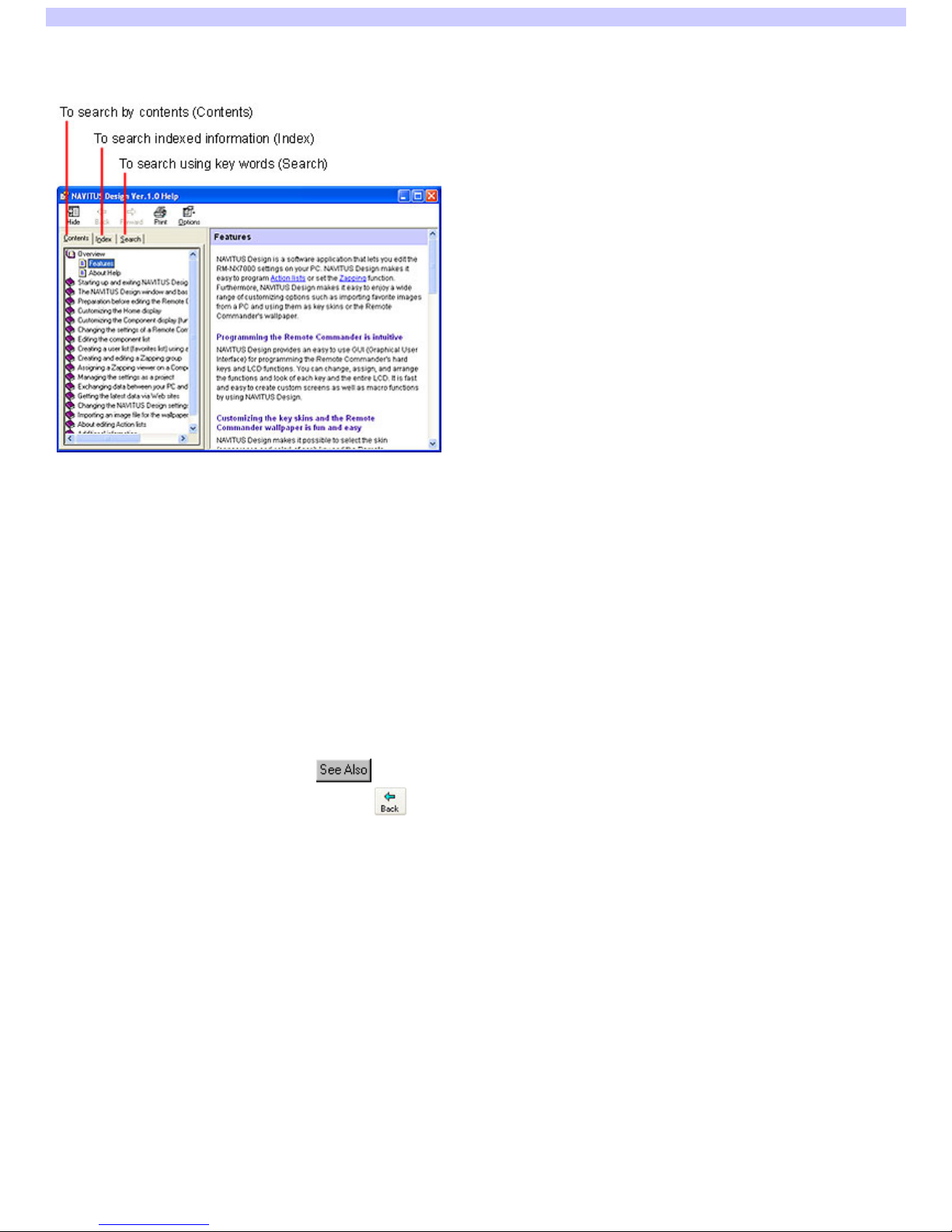
To search by contents (Contents)
When you select the "Contents" tab in the left frame, a table of contents (Contents) w ill appear. The topic titles are listed in the left frame (e.g., "Creating a
Component key" and "Changing the w allpaper of the Home display," etc.). If you click a topic you w ant to look at, the explanation of the topic appears in the
right frame.
To search indexed information (Index)
When you click the "Index" tab, a list of predetermined keyw ords appears in the left frame. If you type in the first several letters of the keyw ord in the "Type in
the keyw ord to find" field (or select a keyw ord from the list) and click "Display," the explanation relating to the keyw ord is show n in the right frame.
To search using key words (Search)
When you click the "Search" tab, the display is sw itched to "Search" in the left frame. If you enter a w ord or phrase into the "Type in the keyw ord to find" field
and click "Display," a list of items containing the w ord(s) will appear in the left frame. If you click an item on this list, the explanation w ill be show n in the right
frame.
The w ord(s) you entered is highlighted in the explanation.
To toggle between related information and the currently viewed explanation
When you click an underlined character string or , you may see detailed information of the topic in the right frame. If you w ant to return to the
previous screen after reading through the explanation, click at the top of the w indow . The previous screen reappears.
Page 2

Starting up NAVITUS Design
1.
Click the "Start" button on Window s, and point to "All Programs." The n click "Sony NAVITUS" follow ed by "NAVITUS De sign 1.0."
NAVITUS Design starts up.
Hints
If you are using an operating system other than Window s XP, click the "Start" button on Window s, and point to "Programs." Then click "Sony NAVITUS"
follow ed by "NAVITUS Design 1.0."
NAVITUS Design can also be started up in the follow ing w ays:
If (the shortcut icon of NAVITUS Design) is show n on the desktop of Window s, double-click the icon. (Depending on the setting, Window s XP
deletes icons from the desktop if they have not been used for a certain period of time. If is not show n on the desktop, use the "Start" button to
start up NAVITUS.)
After displaying the files in the NAVITUS Design project folder using Window s Explorer, etc., double-click the NAVITUS Design file w ith an .nxe
extension. (In this case, NAVITUS Design starts up, opening the project associated w ith the NAVITUS Design file you double-clicked.)
Page 3

Exiting NAVITUS Design
1.
Click in the uppe r right corner of NAVITUS De s ign.
Alternative ly, click "File" from the m e nu bar, then s ele ct "Exit."
NAVITUS Design closes.
Hint
If you try to exit NAVITUS Design w ithout saving the project you are editing, a dialog box appears to confirm the saving. To save the project you are editing,
click "Save." If you do not w ant to save the project, click "Don't save."
Page 4
The NAVITUS Design window reference
When you start up NAVITUS Design and open a project, the follow ing display appears.
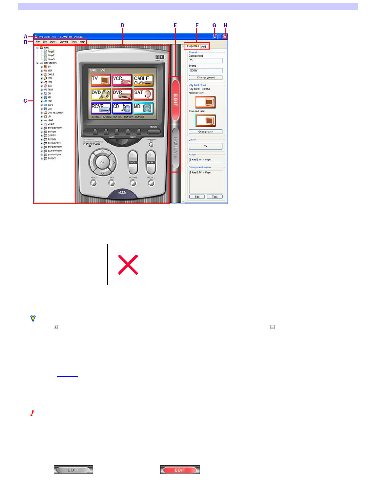
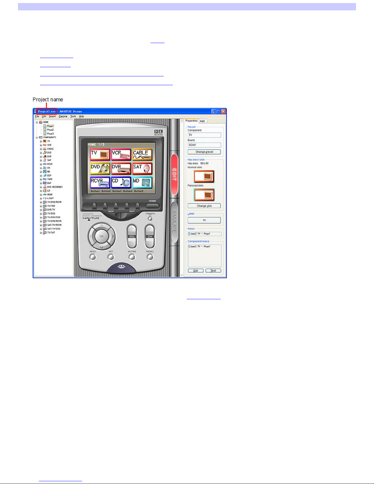
A Title bar
Displays "Project name - NAVITUS Design" w hen a project on NAVITUS Design is open.
When no project is open, the title bar displays only "NAVITUS Design." The project name is not displayed.
B Menu bar
Displays the NAVITUS Design menu.
C Page tree vie w
Displays every page of the Home display and each Component display in a tree view . If you click the page you w ant to edit from the Page tree view , keys
on the page (Component keys, function keys, etc.) are displayed on the editor in the center of the w indow .
Hint
If you click on the left side of each item, the items under the selected item (pages, etc.) are displayed. If you click , the items under the selected item
are hidden.
D Editor
The keys and buttons you w ant to edit are illustrated by a graphic image similar to the Remote Commander.
The top of the editor (touch panel s creen part of the Re mote Com m ander)
The keys (Component keys, function keys, etc.) on the selected page are displayed. If you click a key on the editor, you can edit the key settings (skin,
label, and Action list, etc.) w ith the "Properties" tab on the right side of the w indow .
You can also change the assignment of a key or delete a key on the editor.
The bottom of the editor
The function buttons of the Remote Commander are illustrated. If you click the button on the editor, you can edit its Action list, etc., w ith the "Properties"
tab on the right side of the w indow .
Note
The follow ing function buttons cannot be edited, so you cannot select them on the editor.
HOME button
BACK button/NEXT button
COMMANDER OFF button
E EDIT sw itch/EM ULATE sw itch
Sw itches betw een the EDIT mode and the EMULATE mode.
If you click , the sw itch display changes to , and NAVITUS Design is set to the EDIT mode. You can edit the settings
of the Remote Commander's keys and function buttons.
Page 5

If you click , the sw itch display changes to , and NAVITUS Design is set to the EMULATE mode. You can check how
the Remote Commander w ill w ork w hen the Remote Commander's key or function button is pressed, on NAVITUS Design.
Note
If function keys are not programmed for a particular action, they are not displayed in the EMULATE mode or w hen you w ork w ith the Remote Commander.
F Propertie s tab/Add tab
Propertie s tab
You can edit the settings (skin, label, Action list, etc.) of the keys and function buttons selected on the editor.
When no keys or buttons are selected on the editor (but a page is selected), you can set the w allpaper for the Home display or the Component display.
Add tab
You can create a key, w hen you drag and drop a key icon on the Add tab (Component key, function key, or Zapping view er) to w here nothing is
assigned in the upper part of the editor.
G Minimize button
Minimizes the NAVITUS Design display so it is displayed as an icon on the Window s taskbar.
H Close button
Exits NAVITUS Design.
Page 6
Basic operations
NAVITUS Design lets you edit by the follow ing procedures.
(1) Display the project you want to edit on NAVITUS Design
To edit on NAVITUS Design, first you need to display the project you w ant to edit.
Right after you start up NAVITUS Design, no project is displayed. Display a project in one of the follow ing w ays:
Create a project
Open a project
Upload the Remote Commander settings to NAVITUS Design
Import the settings saved on a Memory Stick to NAVITUS Design
When the project is displayed, its name appears on the title bar, and you are ready to edit the Remote Commander settings on NAVITUS Design.
(2) Edit the Remote Commander settings in the EDIT mode
When the project is displayed, follow the steps below to edit the keys and function buttons.
Page 7
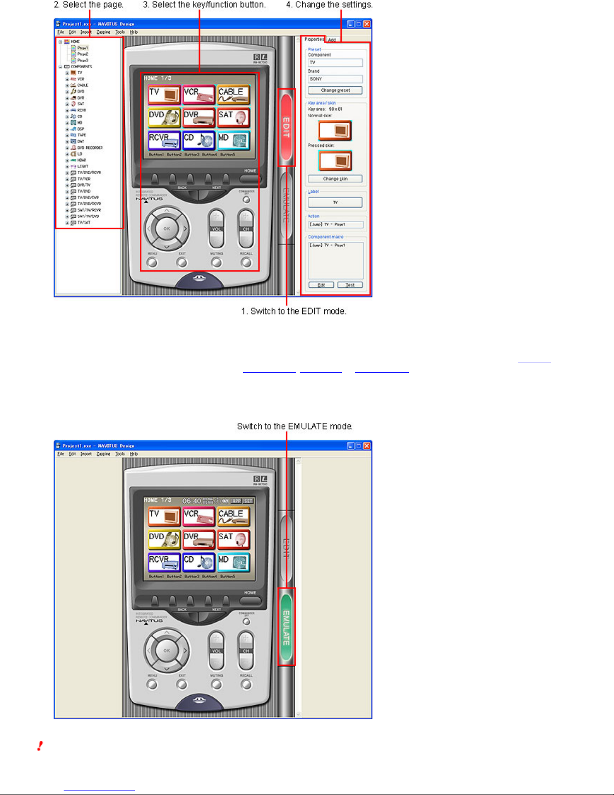
1.
Click the EDIT sw itch to sw itch to the EDIT mode.
2.
Click the page you want to edit from the Page tre e vie w .
3.
Click the k ey or function button you want to edit on the editor.
4.
Edit the s ettings of the ke y or function button w ith the "Properties" tab.
The "Properties" tab allow s you to edit the various settings of the key or function button, such as the skin appearance, label text, or Action list.
By using the "Add" tab, you can also create a key (Component key, function key, or Zapping view er).
(3) Check the operations of the Remote Commander in the EMULATE mode
When editing is complete, click the EMULATE sw itch to sw itch to the EMULATE mode.
In the EMULATE mode, you can check the operations performed w hen the key or function button is pressed, on NAVITUS Design.
If the key or function button does not w ork properly, return to the EDIT mode to change the settings again.
Notes
In the EMULATE mode, you can only check the visual aspects of the Remote Commander, like page transitions w hen a key or button is pressed or a key's
appearance on the page (assignment, skin, label, etc.). Using NAVITUS Design, you cannot check how AV components w ill respond to buttons being
pressed on the Remote Commander. To check the actual operations, check the remote control signal of the Action list programmed for each key and button.
Page 8

For further details, see the follow ing topics:
Checking the operations of a Component macro
Checking the operations of the Action list of a function key
Checking the operations of the Action list of a function button
Checking the operations of the Action list of a list element
Checking the operations of the Action list of a Zapping element
Function keys that have no actions programmed for them are not displayed in the EMULATE mode or w hen you w ork w ith the Remote Commander.
Page 9
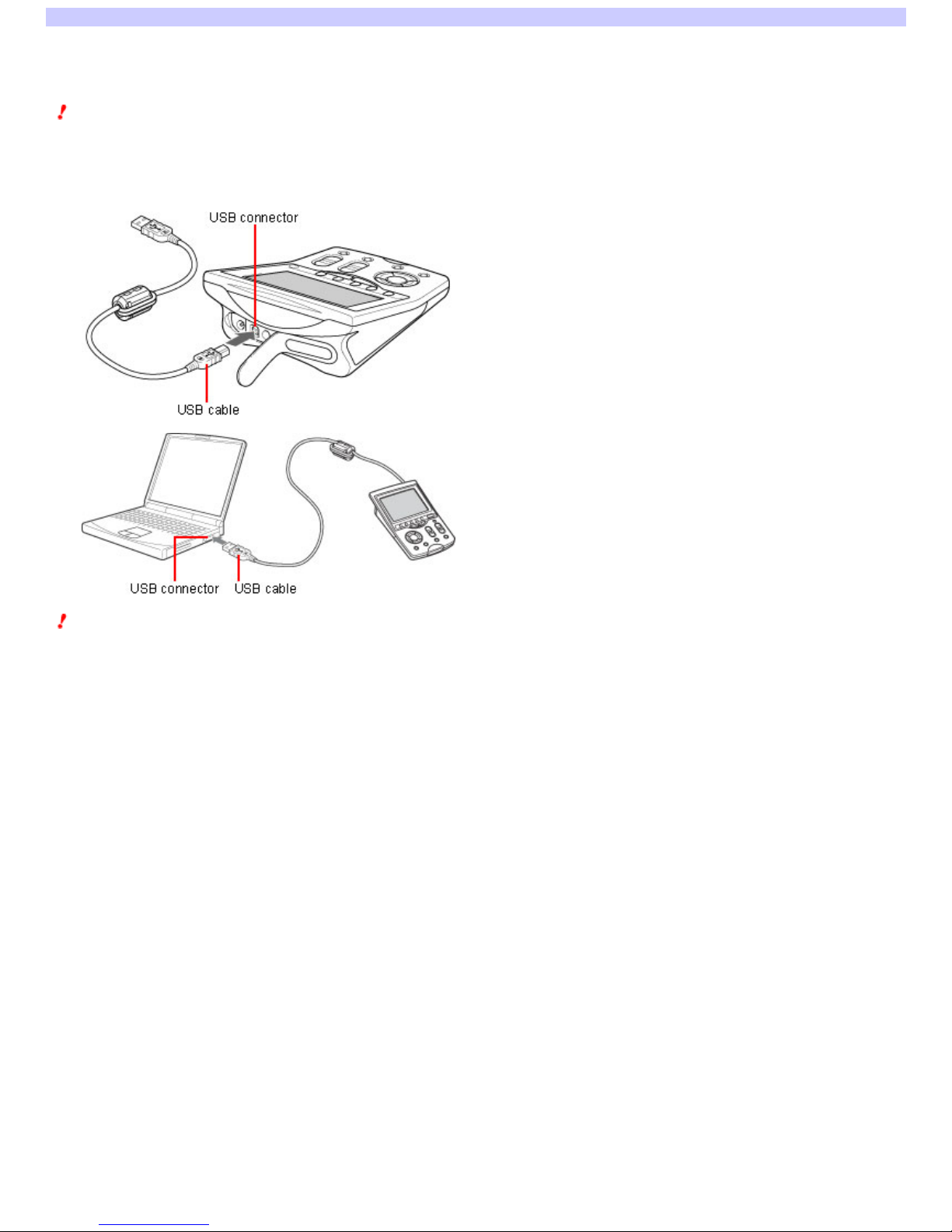
Connecting the Remote Commander to your PC
You can connect the Remote Commander (RM-NX7000) to your PC w ith the supplied USB cable. When you check the remote control signal of the Action list
programmed for the keys and buttons, or w hen you exchange setting data betw een your PC and the Remote Commander, connect the Remote Commander to
your PC.
Notes
Before connecting the Remote Commander to your PC, be sure to connect the supplied AC pow er adaptor to the Remote Commander.
Do not disconnect the USB cable from your PC w hile your PC is communicating w ith the Remote Commander, as a malfunction may occur.
Do not connect several Remote Commanders to your PC at the same time, as your PC w ill not be able to communicate w ith the Remote Commander.
1.
Connect the USB cable to the USB conne ctor of the Re m ote Com m ande r (RM-NX7000).
2.
Connect the USB cable to the USB conne ctor of your PC.
Note
When you connect the Remote Commander (RM-NX7000) to your PC for the first time, the USB driver install w izard appears. For further installation details,
refer to the supplied operating instructions.
Page 10
Uploading the Remote Commander settings to NAVITUS Design
You can upload the Remote Commander settings to NAVITUS Design w ith the USB cable and save them as a project.
1.
Connect the Re m ote Commander to your PC w ith the USB cable.
Notes
o
Before connecting the Remote Commander to your PC, be sure to connect the supplied AC pow er adaptor to the Remote Commander.
o
Do not disconnect the USB cable from your PC until uploading of the Remote Commander settings is complete, as a malfunction may occur.
o
Do not connect several Remote Commanders to your PC at the same time, as you w ill not be able to upload the Remote Commander settings. Connect
only the RM-NX7000.
2.
Click "File" of the m e nu bar, then s ele ct "Upload from NX7000."
The "Upload from NX7000" dialog box appears.
Hint
If the project you are editing is not saved, a dialog box appears to confirm the saving before the "Upload from NX7000" dialog box appears. To save the
project, click "Save." If you do not w ant to save the project, click "Don't save."
3.
Click "Upload."
Uploading of the Remote Commander settings starts. When uploading is complete, the "Save uploaded data as" dialog box appears, w hich allow s you to
save the Remote Commander settings as a project.
4.
Ente r a project folde r nam e on the right side of in "Input a project folde r nam e."
5.
Click .
A dialog box appears to select a folder.
6.
Select the folder in which you want to save the proje ct, then click "OK."
The display returns to the "Save uploaded data as" dialog box, and the selected folder is displayed on the left side of .
7.
Click "OK."
The "Save uploaded data as" dialog box closes, and the uploaded settings are saved under the project name entered in step 4. They are also displayed
on NAVITUS Design.
Page 11
Importing the settings saved on a Memory Stick to NAVITUS Design
You can import the settings saved on a Memory Stick to NAVITUS Design. The setting data you can import is as follow s:
Full data set
Includes all the Remote Commander settings.
See "Importing all the Remote Commander settings."
Component data
Includes the settings of a specific component.
See "Adding the settings of a specific component to a current project."
Pres et table
Includes the preset code list (preset table).
See "Importing the preset code list to NAVITUS Design."
Notes
A single Memory Stick can contain only one of the above.
Do not remove the Memory Stick from the Memory Stick slot w hile importing data. Doing so may cause a malfunction.
Importing all the Remote Commander settings (Full data set)
1.
Inse rt the M e m ory Stick that contains the Full data se t into an available Mem ory Stick slot of your PC.
2.
Click "File" of the m e nu bar and point to "Me m ory Stick," the n sele ct "Im port from Mem ory Stick."
All the Memory Stick slots that are available on your PC are searched. When the Memory Stick that contains the Remote Commander settings is found,
the "Import from Memory Stick" dialog box appears.
The "Import from Memory Stick" dialog box displays the setting data type (Full data set) and the last date of setting data.
Hint
If several Memory Sticks containing the setting data are found, a dialog box appears to select a Memory Stick before the above dialog box appears. In
this dialog box, select the Memory Stick from w hich you w ant to import the data, then click "OK" to display the "Import from Memory Stick" dialog box.
3.
Confirm the type (Full data se t) and the last date of data setting, then click "Im port."
Importing of the data settings saved on the Memory Stick starts. When importing is complete, the "Save as" dialog box appears, w hich allow s you to
save the settings from the Memory Stick as a project.
Hint
If the project you are editing is not saved, a dialog box appears to confirm the saving before importing of the setting data starts. To save the project,
click "Save." If you do not w ant to save the project, click "Don't save."
4.
Ente r a project folde r nam e on the right side of in "Input a project folde r nam e."
5.
Click .
A dialog box appears to select a folder.
6.
Select the folder in which you want to save the proje ct, then click "OK."
The display returns to the "Save as" dialog box, and the selected folder is displayed on the left side of .
7.
Click "OK."
The "Save as" dialog box closes, and the imported settings are saved under the project name entered in step 4. They are also displayed on NAVITUS
Design.
Adding the settings of a specific component to a current project (Component data)
1.
Open the project in which you want to add the com ponent se ttings.
2.
Inse rt the M e m ory Stick that contains the Component data into an available Mem ory Stick slot of your PC.
3.
Click "File" of the m e nu bar and point to "Me m ory Stick," the n sele ct "Im port from Mem ory Stick."
All the Memory Stick slots that are available on your PC are searched. When the Memory Stick that contains the Remote Commander settings is found,
the "Import from Memory Stick" dialog box appears.
The "Import from Memory Stick" dialog box displays the setting data type (Component data) and the last date of setting data.
Hint
If several Memory Sticks containing the setting data are found, a dialog box appears to select a Memory Stick before the above dialog box appears. In
this dialog box, select the Memory Stick from w hich you w ant to import the data, then click "OK" to display the "Import from Memory Stick" dialog box.
4.
Confirm the type (Component data) and the last date of data setting, then click "Im port."
Importing of the setting data saved on the Memory Stick starts. When importing is complete, the imported settings are added to the displayed project.
Importing the preset code list to NAVITUS Design (Preset table)
1.
Close any currently open project files on NAVITUS Design.
2.
Inse rt the M e m ory Stick that contains the Pres et table into an available Mem ory Stick slot of your PC.
Page 12

3.
Click "File" of the m e nu bar and point to "Me m ory Stick," the n sele ct "Im port from Mem ory Stick."
All the Memory Stick slots that are available on your PC are searched. When the Memory Stick that contains the Remote Commander settings is found,
the "Import from Memory Stick" dialog box appears.
The "Import from Memory Stick" dialog box displays the setting data type (Preset table) and the last date of data setting.
Hint
If several Memory Sticks containing the setting data are found, a dialog box appears to select a Memory Stick before the above dialog box appears. In
this dialog box, select the Memory Stick from w hich you w ant to import the data, then click "OK" to display the "Import from Memory Stick" dialog box.
4.
Confirm the type (Pres et table ) and the last date of se tting data, then click "Im port."
The Preset table saved on the Memory Stick is imported to NAVITUS Design.
Page 13

About editing the Home display and Component keys
The Home display is first show n w hen you turn on the Remote Commander. Keys to select an AV component you w ant to operate w ith the Remote
Commander (Component keys) are displayed in a line in the Home display. When you click a Component key of the AV component you w ant to control, the
display to control the AV component (Component display) appears.
NAVITUS Design allow s the follow ing editing options for Component keys and Home display:
Editing the Compone nt ke ys
Changing the skin (key appearance and color)
Changing the label
Changing the preset
Editing the Action list (Component macro)
Checking the operations of a Component macro
Creating a Component key
Creating an Alias Component key by combining existing function keys
Changing the assignment
Copying a Component key
Deleting a Component key
Editing the Hom e display
Adding a page
Changing the w allpaper
Deleting a page
See also
About editing the Component display and function keys
About editing function buttons
About the component list
About the Zapping function
Page 14
Changing the skin (key appearance and color) of a Component key
You can change the skin (key appearance and color) of a Component key. You can also customize the skin of a Component key by importing your favorite
image from your PC.
1.
Click the EDIT sw itch in the cente r of the w indow to s w itch to the EDIT m ode.
2.
Click the page that includes the Com ponent ke y you w ant to edit from the Page tre e vie w on the left.
The Component keys of the selected page appear on the editor in the center of the w indow .
3.
Click the Com ponent k ey w hose s k in you w ant to change on the e ditor.
4.
Click the "Properties" tab in the upper right of the w indow.
5.
Click "Change s kin" on the right side of the w indow .
The "Change skin" dialog box appears.
The normal skin (as show n w hen the key is not clicked) is displayed on the left side of the "Change skin" dialog box. The pressed skin (w hen the key is
clicked) is displayed on the right side.
Hint
If you click "Import skin" at the bottom of the "Change skin" dialog box, the "Import skin" dialog box appears and you can import an image file for the skin.
The imported image file can be selected as the skin of the Component key etc.
6.
Click "Sele ct bitm ap" of "Norm al skin."
The "Bitmap selection" dialog box appears.
7.
Select the new sk in from the s k in list.
Hint
To select the imported image file, click of "Skin type" and select "Imported files" from the drop-dow n list. The imported image files are displayed on
the skin list.
Notes
The skin list displays only the same-sized skin (key area size) as the old key. You cannot select a different-sized skin from the old key.
The key area size of the Component key is fixed at 98 x 61 pixel. You cannot change the key area size.
8.
Click "OK."
The display returns to the "Change skin" dialog box, and the skin selected in step 7 is displayed in the normal skin preview .
9.
Click "Sele ct bitm ap" of "Press ed s kin."
The "Bitmap selection" dialog box appears.
10.
Click the new sk in from the sk in lis t.
Hint
To select the imported image file, click of "Skin type" and select "Imported files" from the drop-dow n list. The imported image files are displayed on
the skin list.
Notes
The skin list displays only the same-sized skin (key area size) as the old key. You cannot select a different-sized skin from the old key.
The key area size of the Component key is fixed at 98 x 61 pixel. You cannot change the key area size.
11.
Click "OK."
The display returns to the "Change skin" dialog box, and the skin selected in step 10 is displayed in the pressed skin preview .
12.
Click "OK."
The "Change skin" dialog box closes, and the skin of the Component key (selected in step 3) is changed.
Hints
You can check in the EMULATE mode if the changed skin is displayed properly. To sw itch to the EMULATE mode, click the EMULATE sw itch in the center of
the w indow .
The image file for the skin can also be imported by clicking "Import" of the menu bar, then selecting "Skin" or "Skin (Package Import)."
Page 15
Changing the label of a Component key
You can change the label (name) of a Component key.
1.
Click the EDIT sw itch in the cente r of the w indow to s w itch to the EDIT m ode.
2.
Click the page that includes the Com ponent ke y you w ant to edit from the Page tre e vie w on the left.
The Component keys of the selected page appear on the editor in the center of the w indow .
3.
Click the Com ponent k ey w hose labe l you w ant to change on the e ditor.
4.
Click the "Properties" tab in the upper right of the w indow.
5.
Click the button of "Label" on the right side of the w indow .
The "Input label" dialog box appears, w hich allow s you to set the follow ing items:
o
Label
o
Enter the characters to be displayed as the label. You can enter up to 32 letters and can start a new line.
o
Furthermore, you can enter symbols such as (record) or (stop) in the "Symbol select" dialog box. The "Symbol select" dialog box can be
displayed by clicking "Symbol." (One symbol is counted as four standard letters.)
Notes
The label cannot be left blank. Be sure to enter at least one letter.
You cannot set the same label as an existing Component key.
Hint
You can copy and paste text in the text box of "Label" by using the shortcut menu (right-click menu) or by using the shortcut keys.
o
Font size
o
Select the font size from the drop-dow n list by clicking .
o
You can select "Small," "Medium," or "Large."
o
Text color
The text color is displayed in the text color box. You can select another color for the label by clicking "Change color" to display the "Color select"
dialog box.
o
Text align
o
Select the alignment of text in the Component key from the drop-dow n list by clicking .
o
You can select either "Center" or "Top - Left."
o
Pres s gap
o
Select the Component key gap (the direction/distance the label moves to w hen the Component key is pressed) from the drop-dow n list by clicking
.
o
The gap value ranges from -5 to 5. If the value is below zero, the label moves to the upper left w hen the Component key is pressed. If the value is
above zero, the label moves to the low er right w hen the Component key is pressed.
o
Dis play label on the s kin
o
Select w hether to display the characters (that you entered in the "Label" box) on the Component key. If you uncheck this box, the characters are
hidden.
Hint
If you change the label settings, the changed label is displayed in the "Preview " area in the low er left of the dialog box.
6.
Click "OK."
The "Input label" dialog box closes, and the label of the Component key (selected in step 3) is changed.
Hint
You can check in the EMULATE mode if the changed label is displayed properly. To sw itch to the EMULATE mode, click the EMULATE sw itch in the center of
the w indow .
Page 16
Changing the preset of a Component key
You can change the presets (the brands of AV components and the preset codes) programmed for the Component keys.
This operation allow s you to change only preset actions (Preset action or Preset_empty action) programmed for the keys and function buttons assigned to the
component. The contents you edited on the Component display (addition/change/deletion of keys, and addition/deletion of pages) cannot be changed.
Change the preset of the Component key w hen you buy a new AV component, or create new projects, etc.
Note
You cannot change the setting of a component (category of AV components) from the factory-preset code for the Component key.
1.
Click the EDIT sw itch in the cente r of the w indow to s w itch to the EDIT m ode.
2.
Click the page that includes the Com ponent ke y you w ant to edit from the Page tre e vie w on the left.
The Component keys of the selected page appear on the editor in the center of the w indow .
3.
Click the Com ponent k ey w hose pre set you want to change on the editor.
4.
Click the "Properties" tab in the upper right of the w indow.
5.
Click "Change preset" of "Pre set" on the right side of the w indow.
The "Change preset" dialog box appears, w hich allow s you to change brands (AV component brand) and code sets (preset code.)
o
Brands
o
Select the new brand name of AV component from the drop-dow n list by clicking .
o
Code s e ts
o
Select the new preset code from the drop-dow n list by clicking .
Hint
If several preset codes are displayed in "Code sets," you can check the remote control signal of the selected preset code by clicking "Test your
code set." Follow steps 6 to 10 and specify the preset code of your AV component.
How ever, if the display show s only one preset code in "Code sets," or you already know the preset code of your AV component, you do not need
to check the remote control signal. Go to step 11.
6.
Connect your Re m ote Com m ander to your PC using the USB cable.
If the display show s only one preset code in "Code sets" in step 5, or you already know the preset code of your AV component, you do not need to
check the remote control signal. Go to step 11.
Notes
o
Before connecting the Remote Commander to your PC, be sure to connect the supplied AC pow er adaptor to the Remote Commander.
o
While checking the remote control signal, do not disconnect the USB cable from your PC. Doing so may cause a malfunction.
o
Do not connect several Remote Commanders to your PC at the same time, as you w ill not be able to check the remote control signal.
7.
Click "Tes t your code s e t."
The "Test your code set" dialog box appears, w hich allow s you to check the remote control signal of the selected preset code.
8.
Follow the instructions in the "Te st your code s et" dialog box and prepare the AV com ponent for w hich the code is to be
programmed.
9.
Aim the Re m ote Com m ander at the AV com ponent of w hich the code is to be programme d, then click "Se nd IR."
The highlighted action (as appears on a list) is transmitted as the remote control signal. Check if the AV component functions properly.
After the remote control signal is transmitted, the next action on the list w ill be highlighted. By clicking "Send IR," the action is transmitted as the remote
control signal. Check all actions on the list, repeating this operation.
Hint
If you click "Test again," you can recheck the remote control signal from the top of the list.
10.
When the check of the rem ote control signal is complete , click "Clos e ."
The "Test your code set" dialog box closes, and the display returns to the "Change preset" dialog box.
Hint
If the AV component does not respond properly to the remote control signal, return to step 5 to reset the preset code, then recheck the signal.
11.
Click "OK."
The "Change preset" dialog box closes, and the preset of the Component key (selected in step 3) is changed.
Page 17
Editing the Action list of a Component key (Component macro)
You can edit Action lists (Component macros) programmed for the Component keys.
What is a Com ponent macro?
The Component keys on the Home display have their ow n actions (Jump action) to jump to Page 1 of each Component display. This action is performed w hen
the Component keys are briefly pressed.
Furthermore, by programming a "Component macro," you can program a series of actions (Action list) to be performed w hen a Component key is pressed for a
longer time. After that, you can jump to Page 1 of the Component display.
For example, if you program a Component macro for the TV Component key, operations such as turning on the TV and sw itching the Home display to Page 1 of
the TV Component display can be performed automatically by simply pressing the key for longer.
1.
Click the EDIT sw itch in the cente r of the w indow to s w itch to the EDIT m ode.
2.
Click the page that includes the Com ponent ke y you w ant to edit from the Page tre e vie w on the left.
The Component keys of the selected page appear on the editor in the center of the w indow .
3.
Click the Com ponent k ey w hose Action lis t (Com ponent m acro) you w ant to edit on the e ditor.
4.
Click the "Properties" tab in the upper right of the w indow.
5.
Click "Edit" of "Com pone nt macro" on the right s ide of the w indow .
The "Edit actions" dialog box appears, w hich allow s you to set the length of time for w hich you need to press the Component key to execute the Action
list (key-pressed time). You can also add, change or delete the Component key action, or change the action order.
o
Set ke y-pres sed time
o
Select the key-pressed time from the drop-dow n list by clicking .
o
The key-pressed time ranges from 1 to 10 seconds. The default setting is 2.
o
Action list
o
A series of actions, programmed as a Component macro, are displayed as a list. Only the action to jump to Page 1 of the Component display is set as
the default.
o
To edit an action on the Action list, double-click the action, or click the action and press the Enter key on your keyboard.
o
/
o
Change the action order.
o
If you select an action on the Action list and click , the selected action moves one step up.
o
If you select an action on the Action list and click , the selected action moves one step dow n.
Hints
You can also change the action order by dragging and dropping on the Action list.
The action to jump to Page 1 of the Component display alw ays appears on the last of the Action list. You cannot change the action order.
o
Alias
o
Add an Alias action to the Action list.
o
When you click "Alias," the "Alias" dialog box appears, w hich allow s you to program the Component key to perform the same action as w hen other
keys or function buttons on the Remote Commander are pressed.
Note
You cannot program an Alias action that w ill cause an "alias loop." For further details, see "About alias loops."
o
De lay
o
Add a Delay action to the Action list.
o
When you click "Delay," the "Set delay time" dialog box appears, w hich allow s you to set an interval (delay time) betw een actions.
o
De lete
Delete the selected action on the Action list by clicking "Delete."
Hints
You can also delete an action by selecting it on the Action list and pressing the Delete key on your keyboard.
The action to jump to Page 1 of the Component display cannot be deleted.
6.
Click "OK."
The "Edit actions" dialog box closes, and the Action list of the Component key (selected in step 3) is changed.
Hint
Page 18

You can check if the new Component macro functions properly by clicking "Test" on the "Properties" tab.
Page 19

Checking the operations of a Component macro
You can check the operations of an Action List (Component macro) programmed for a Component key.
After connecting the Remote Commander to your PC and transmitting the remote control signal of the Component macro, check if the AV component functions
as you programmed.
1.
Connect the Re m ote Commander to your PC w ith the USB cable.
Notes
o
Before connecting the Remote Commander to your PC, be sure to connect the supplied AC pow er adaptor to the Remote Commander.
o
While checking the operations of a Component macro, do not disconnect the USB cable from your PC. Doing so may cause a malfunction.
o
Do not connect several Remote Commanders to your PC at the same time, as you w ill not be able to check the remote control signal.
2.
Click the EDIT sw itch in the cente r of the w indow to s w itch to the EDIT m ode.
3.
Click the page that includes the Com ponent ke y you w ant to check from the Page tree vie w on the left.
The Component keys of the selected page appear on the editor in the center of the w indow .
4.
Click the Com ponent k ey w hose action (of a Com ponent macro) you want to check on the e ditor.
5.
Click the "Properties" tab in the upper right of the w indow.
6.
Click "Tes t" of "Com ponent m acro" on the right side of the w indow.
The "Test IR" dialog box appears, and connection w ith the Remote Commander is confirmed. When the confirmation is complete, you can click "Test" in
the dialog box.
7.
Aim the Re m ote Com m ander at the AV com ponent of w hich the operation is to be check ed, then click "Test."
The macro of the Component key (selected in step 4) is transmitted as the remote control signal. Check if the AV component functions as you
programmed.
Hint
If the AV component does not function properly, check the settings of "Component macro" of the "Properties" tab.
If the Component macro settings are not correct, click "Edit" and edit the Action list.
Page 20
Creating a Component key
You can create a Component key by programming the preset code for the AV component.
Create another Component key, w hen you operate another AV component using the RM-NX7000 (for example, w hen you buy a new AV component).
1.
Click the EDIT sw itch in the cente r of the w indow to s w itch to the EDIT m ode.
2.
Click the page on which you w ant to create a Com ponent k ey from the Page tre e vie w on the left.
The selected page appears on the editor in the center of the w indow .
Hint
You can also create a Component key on a new page. To create a new page, click "Edit" of the menu bar, then "Add Blank Page."
3.
Click the "Add" tab in the upper right of the w indow .
The Component key icon appears in the upper right of the w indow .
4.
Drag and drop the Com ponent ke y icon w here nothing is as signed.
The "Add component" w izard appears.
Note
You cannot drag and drop a Component key icon w here a Component key is already assigned.
5.
Click "New com ponent," the n click "Next."
The "Note for adding a new component" display appears.
6.
Click "Next."
The "IR selection" display appears, w hich allow s you to set the follow ing items:
o
Components
o
Select the AV component category for the Component key from the drop-dow n list by clicking .
If you select "(NONE)," an empty Component key that is not programmed w ith the preset code of AV component is created. In this case, after creating
an empty Component key, program the preset code, etc., for the Component key.
o
Brands
o
Select the brand name of AV component for the Component key from the drop-dow n list by clicking .
o
Code s e ts
o
Select the preset code for the Component key from the drop-dow n list by clicking .
Hint
If several preset codes are displayed in "Code sets," you can check the remote control signal of the selected preset code by clicking "Test your
code set." Follow steps 7 to 11 and specify the preset code of your AV component.
How ever, if the display show s only one preset code in "Code sets," or you already know the preset code of your AV component, you do not need
to check the remote control signal. Go to step 12.
7.
Connect your Re m ote Com m ander to your PC with the USB cable .
If the display show s only one preset code in "Code sets" in step 6, or you already know the preset code of your AV component, you do not need to
check the remote control signal. Go to step 12.
Notes
o
Before connecting the Remote Commander to your PC, be sure to connect the supplied AC pow er adaptor to the Remote Commander.
o
While checking the remote control signal, do not disconnect the USB cable from your PC. Doing so may cause a malfunction.
o
Do not connect several Remote Commanders to your PC at the same time, as you w ill not be able to check the remote control signal.
8.
Click "Tes t your code s e t."
The "Test your code set" dialog box appears, w hich allow s you to check the remote control signal of the selected preset code.
9.
Follow the instructions in the "Te st your code s et" dialog box and prepare the AV com ponent for w hich the code is to be
programmed.
10.
Aim the Re m ote Com m ander at the AV com ponent for w hich the code is to be programme d, then click "Se nd IR."
The highlighted action (as appears on the list) is transmitted as the remote control signal. Check if the AV component functions properly.
After the remote control signal is transmitted, the next action on the list w ill be highlighted. By clicking "Send IR," the action is transmitted as the remote
control signal. Check all actions on the list, repeating this operation.
Hint
If you click "Test again," you can recheck the remote control signal from the top of the list.
11.
When the check of the rem ote control signal is complete , click "Clos e ."
The "Test your code set" dialog box closes, and the display returns to the "IR selection" dialog box.
Hint
If the AV component does not respond properly to the remote control signal, return to step 6 to reset the preset code, then recheck the signal.
12.
Click "Next."
The "Label input" display appears, w hich allow s you to set the follow ing items:
o
Label
o
Enter the characters to be displayed as the label. You can enter up to 32 letters and can start a new line.
o
Furthermore, you can enter symbols such as (record) or (stop) in the "Symbol select" dialog box. The "Symbol select" dialog box can be
displayed by clicking "Symbol." (One symbol is counted as four standard letters.)
Notes
Page 21
The label cannot be left blank. Be sure to enter at least one letter.
You cannot set the same label as an existing Component key.
Hint
You can copy and paste text in the text box of "Label" by using the shortcut menu (right-click menu) or by using the shortcut keys.
o
Font size
o
Select the font size from the drop-dow n list by clicking .
o
You can select "Small," "Medium," or "Large." The default setting is "Large."
o
Text color
The text color is displayed in the text color box. You can select another color for the label by clicking "Change color" to display the "Color select"
dialog box.
o
Text align
o
Select the alignment of text in the Component key from the drop-dow n list by clicking . You can select either "Center" or "Top - Left." The default
setting is "Center."
o
Pres s gap
o
Select the Component key gap (the direction/distance the label moves to w hen the Component key is pressed) from the drop-dow n list by clicking
. The gap value ranges from -5 to 5. If the value is below zero, the label moves to the upper left w hen the Component key is pressed. If the value
is above zero, the label moves to the low er right w hen the Component key is pressed. The default setting is 2.
o
Dis play label on the s kin
o
Select w hether to display the characters (that you entered in the "Label" box) on the Component key. If you uncheck this box, the characters are
hidden. This box is checked by default.
Hint
If you change the label settings, the changed label is displayed in the "Preview " area in the low er left of the dialog box.
13.
Click "OK."
The "Add component" w izard closes, and the new Component key is created for the page selected in step 2.
Hint
You can check in the EMULATE mode if the new Component key has been created properly. To sw itch to the EMULATE mode, click the EMULATE switch in the
center of the w indow .
Page 22
Creating an Alias Component key by combining existing function keys
You can create an Alias Component key, by combining existing function keys.
An Alias Component key allow s you to create a multi-component key that can operate multiple AV components in one Component display. For example, to
control a DVD, create an Alias key to operate your DVD, RCVR (Receiver), and TV (all of w hich are needed to w atch a DVD). You can then operate these
three components in one display w ithout sw itching to each component display.
Hint
NAVITUS Design provides an Alias Component key (multi-component key) w ith combination of AV components you often use, by default.
1.
Click the EDIT sw itch in the cente r of the dis play to sw itch to the EDIT mode.
2.
Click the page on which you w ant to create a Com ponent k ey from the Page tre e vie w on the left.
The selected page appears on the editor in the center of the display.
Hint
You can create a Component key on a new page. To create a new page, click "Edit," then "Add Blank Page."
3.
Click the "Add" tab in the upper right of the display.
The Component key icon appears in the upper right of the display.
4.
Drag and drop the Com ponent ke y icon w here nothing is as signed.
The "Add component" w izard appears.
Note
You cannot drag and drop a Component key icon w here a Component key is already assigned.
5.
Click "Alias com ponent," then "Ne xt."
The "Create alias component" display appears.
The "Original component" (source component) page is displayed on the left side of the "Create alias component" display, and the "Alias component"
(reference component) page is on the right side.
6.
Click of "Page" of "Original component" to sele ct the page that include s the function ke y of the original compone nt.
The function keys of the selected page appear on the left side of the display.
7.
Select the function key of the original component, then drag and drop it on the page of "Alias com ponent."
The selected function key appears on the "Alias component" page.
Hints
o
If you click "Add new page," you can add a new page in "Alias component." Click of "Page" to select the new page from the drop-dow n list.
o
If you select an image file for the w allpaper from the drop-dow n list by clicking of "Wallpaper," you can change the w allpaper of "Alias
component." The new w allpaper is applied to all pages of "Alias component."
o
From the drop-dow n list of "Wallpaper," you can also select the w allpaper for the multi-component (w allpaper divided into tw o or more.) How ever,
the selection of the divided w allpaper does not affect the assignment of the function keys.
o
If you select the function key on the "Alias component" page and click "Key clear," you can delete the function key.
o
To add a function key from another AV component, return to step 6.
Note
You cannot select a Zapping view er or LIST key as a reference.
8.
Click "Next."
The "Label input" display appears, w hich allow s you to set the label of the Component key.
o
Label
o
Enter the characters to be displayed as the label. You can enter up to 32 letters and can start a new line.
o
Furthermore, you can enter symbols such as (record) or (stop) in the "Symbol select" dialog box. The "Symbol select" dialog box can be
displayed by clicking "Symbol." (One symbol is counted as four standard letters.)
Notes
The label cannot be left blank. Be sure to enter at least one letter.
You cannot set the same label as an existing Component key.
Hint
You can copy and paste text in the text box of "Label" by using the shortcut menu (right-click menu) or by using the shortcut keys.
o
Font size
o
Select the font size from the drop-dow n list by clicking .
o
You can select "Small," "Medium," or "Large." The default setting is "Large."
o
Text color
The text color is displayed in the text color box. You can select another color for the label by clicking "Change color" to display the "Color select"
dialog box.
o
Text align
o
Select the alignment of text in the Component key from the drop-dow n list by clicking .
o
You can select either "Center" or "Top - Left." The default setting is "Center."
o
Pres s gap
o
Select the Component key gap (the direction/distance the label moves to w hen the Component key is pressed) from the drop-dow n list by clicking
. The gap value ranges from -5 to 5. If the value is below zero, the label moves to the upper left w hen the Component key is pressed. If the value
is above zero, the label moves to the low er right w hen the Component key is pressed. The default setting is 2.
Page 23

o
Dis play label on the s kin
o
Select w hether to display the characters (that you entered in the "Label" box) on the Component key. If you uncheck this box, the characters are
hidden. This box is checked by default.
Hint
If you change the label settings, the changed label is displayed in the "Preview " area in the low er left of the dialog box.
9.
Click "OK."
The "Add component" w izard closes, and the new Alias Component key is created on the page selected in step 2.
Hint
You can check in the EMULATE mode if the new Alias Component key has been created properly. To sw itch to the EMULATE mode, click the EMULATE switch
in the center of the display.
Page 24

Changing the assignment of a Component key
You can move a Component key on the same page or to another/new page.
You can assign a Component key you often use to Page 1 of the Home display, or assign AV components used together to nearby keys.
To move a key on the same page
To move a key to another/new page
To move a key on the same page
1.
Click the EDIT sw itch in the cente r of the w indow to s w itch to the EDIT m ode.
2.
Click the page that includes the Com ponent ke y you w ant to m ove from the Page tre e vie w on the left.
The Component keys of the selected page appear on the editor in the center of the w indow .
3.
Click the Com ponent k ey you w ant to move , then drag and drop it w he re you w ant to m ove it.
If there is no Component key at the place w here you w ant to move the key, the key moves there.
If there is another Component key w here you w ant to move the key, the keys sw ap positions.
Hint
If you change the assignment of a Component key on the Home display, the assignment of the components in the Page tree view is also changed.
To move a key to another/new page
1.
Click the EDIT sw itch in the cente r of the w indow to s w itch to the EDIT m ode.
2.
Click the page that includes the Com ponent ke y you w ant to m ove from the Page tre e vie w on the left.
The Component keys of the selected page appear on the editor in the center of the w indow .
3.
Right-click the Com ponent k ey you w ant to move, then point to "M ove to" of the m e nu and se le ct the page to w hich you w ant to
move the key.
The Component key moves to the selected page. If you select "New page" as the page to w hich you w ant to move the key, a new page is added on the
Home display, and the Component key moves to that page.
Hints
You can move a Component key to another page in the follow ing w ays:
Select the Component key on the editor, then select "Move to" from "Edit" of the menu bar to select the page to w hich you w ant to move the key.
Select the Component key on the editor, then drag and drop it to the page in the Page tree view (of the Home display) to w hich you w ant to move the
key.
If you change the assignment of the Component key on the Home display, the assignment of the components in the Page tree view is also changed.
Note
If there is no empty space on the page to assign the Component key, you cannot move it.
Page 25
Copying a Component key
You can copy a Component key.
By copying a Component key, you can create a Component key that includes the same function keys as the original Component key. This operation is useful to
create a Component key based on existing Component key settings.
1.
Click the EDIT sw itch in the cente r of the w indow to s w itch to the EDIT m ode.
2.
Click the page that includes the Com ponent ke y you w ant to copy from the Page tree view on the le ft.
The Component keys of the selected page appear on the editor in the center of the w indow .
3.
Right-click the Com ponent k ey you w ant to copy, then se le ct "Duplicate" from the m enu.
The "Duplicate" dialog box appears, w hich allow s you to set the follow ing items:
o
Label
o
Enter the characters to be displayed as the label. The text that consists of the original Component key label and a number (numbered consecutively
such as "2, 3, 4...") is displayed as the label by default.
o
You can enter up to 32 letters and can start a new line.
o
Furthermore, you can enter symbols such as (record) or (stop) in the "Symbol select" dialog box. The "Symbol select" dialog box can be
displayed by clicking "Symbol." (One symbol is counted as four standard letters.)
Notes
The label cannot be left blank. Be sure to enter at least one letter.
You cannot set the same label as an existing Component key.
Hint
You can copy and paste text in the text box of "Label" by using the shortcut menu (right-click menu) or by using the shortcut keys.
o
Font size
o
Select the font size from the drop-dow n list by clicking .
o
You can select "Small," "Medium," or "Large." The default setting is "Large."
o
Text color
The text color is displayed in the text color box. You can select another color for the label by clicking "Change color" to display the "Color select"
dialog box.
o
Text align
o
Select the alignment of text in the Component key from the drop-dow n list by clicking .
o
You can select either "Center" or "Top - Left." The default setting is "Top - Left."
o
Pres s gap
o
Select the Component key gap (the direction/distance the label moves to w hen the Component key is pressed) from the drop-dow n list by clicking
. The gap value ranges from -5 to 5. If the value is below zero, the label moves to the upper left w hen the Component key is pressed. If the value
is above zero, the label moves to the low er right w hen the Component key is pressed. The default setting is 2.
o
Dis play label on the s kin
o
Select w hether to display the characters (that you entered in the "Label" box) on the Component key. If you uncheck this box, the characters are not
displayed
o
This box is checked by default.
Hint
If you change the label settings, the changed label is displayed in the "Preview " area in the low er left of the dialog box.
4.
Click "OK."
The "Duplicate" dialog box closes, and the new Component key selected in step 3 is copied.
Hints
The copied Component key is assigned on the follow ing space:
When the re is an empty space on the s am e page on w hich the original Com ponent k ey is as signed
The copied Component key is assigned to the empty space on the same page.
When the re is no em pty s pace on the s am e page on w hich the original Com ponent key is as signe d
The copied Component key is assigned to an empty space on the next available space on a follow ing page.
If there is no empty space on the next available space on a follow ing page, a new page is added on the Home display and the Component key is
assigned to that page.
If you select the Component key, then select "Duplicate" from "Edit" of the menu bar, you can also copy the Component key.
Page 26

Deleting a Component key
You can delete a Component key w hen the existing Component key is no longer necessary, such as w hen you buy a new AV component.
Note
If you delete a Component key, the corresponding component pages and function keys on its pages are also deleted.
1.
Click the EDIT sw itch in the cente r of the w indow to s w itch to the EDIT m ode.
2.
Click the page that includes the Com ponent ke y you w ant to dele te from the Page tree view on the left.
The Component keys of the selected page appear on the editor in the center of the w indow .
3.
Right-click the Com ponent k ey you w ant to delete, then se lect "Dele te" from the m e nu.
A dialog box appears to confirm the deletion.
4.
Click "Yes ."
The Component key selected in step 3 is deleted. The corresponding component pages and function keys on its pages are also deleted.
Hint
You can also delete a Component key in the follow ing w ays:
Select the Component key, then select "Delete" from "Edit" of the menu bar.
Select the Component key, then press the Delete key on your keyboard.
Page 27

Adding a page to the Home display
You can add a new page to the Home display.
Create a page w hen you w ant to create a Component key but there is no space to assign it on the existing pages, or w hen you w ant to group existing
Component keys by page.
1.
Click the EDIT sw itch in the cente r of the w indow to s w itch to the EDIT m ode.
2.
Click any page of the Hom e display from the Page tre e vie w on the left.
3.
Click "Edit" of the m e nu bar, then s elect "Add Blank Page ."
A new page is added as the last page of the Home display, and a message dialog box appears.
4.
Click "OK."
Hints
You can also add a new page on the Home display by right-clicking any page of the Home display from the Page tree view , then selecting "Add Blank Page"
from the menu.
Furthermore, you can also add a new page w hen:
You select "New page" as the page w here you w ant to move a Component key.
You copy a Component key on an existing page having no empty space.
Page 28

Changing the wallpaper of the Home display
You can change the w allpaper (screen background) of the Home display.
An image of your choice can be imported from your PC and used as the w allpaper.
1.
Click the EDIT sw itch in the cente r of the w indow to s w itch to the EDIT m ode.
2.
Click any page of the Hom e display from the Page tre e vie w on the left.
3.
Click the "Properties" tab in the upper right of the w indow.
4.
Click of "Wallpaper" on the right s ide of the w indow , then se lect the ne w im age file .
The w allpaper of all pages of the Home display is changed.
Hint
By clicking "Import" of "Wallpaper," or by selecting "Wallpaper" from "Import" of the menu bar, you can import an image file for the w allpaper. The imported
image file can be selected as the w allpaper.
Page 29

Deleting a page of the Home display
You can delete a blank page of the Home display.
Delete any unnecessary pages created after deleting the Component keys of that page.
Notes
You can only delete a blank page. You cannot delete a page on w hich a Component key is assigned.
You cannot delete Page 1 of the Home display.
1.
Click the EDIT sw itch in the cente r of the w indow to s w itch to the EDIT m ode.
2.
Click the page of the Hom e display that you w ant to dele te from the Page tree vie w on the left.
3.
Click "Edit" of the m e nu bar, then s elect "De le te Page ."
The page selected in step 2 is deleted, and a message dialog box appears.
4.
Click "OK."
Hint
You can also delete a blank page of the Home display by right-clicking the page of the Home display from the Page tree view , and then selecting "Delete page"
from the menu.
Page 30
 Loading...