

Sony MSW-M2100, MSW-M2100E, MSW-M2100EP, MSW-M2100P Operation Manual

DIGITAL VIDEOCASSETTE PLAYER
MSW-M2100
MSW-M2100P
MSW-M2100E
MSW-M2100EP
OPERATION MANUAL
1st Edition (Revised 5)
[English]

Before operating the unit, please read this manual
thoroughly and retain it for future reference.
WARNING
To reduce the risk of fire or electric
shock, do not expose this apparatus to
rain or moisture.
To avoid electrical shock, do snot open
the cabinet. Refer servicing to qualified
personnel only.
THIS APPARATUS MUST BE EARTHED.
CAUTION
The apparatus shall not be exposed to dripping or
splashing and no objects filled with liquid, such as vases,
shall be placed on the apparatus.
The unit is not disconnected from the AC power source
(mains) as long as it is connected to the wall outlet, even if
the unit itself has been turned off.
WARNING
Excessive sound pressure from earphones and
headphones can cause hearing loss. In order to use this
product safely, avoid prolonged listening at excessive
sound pressure levels.
For the customers in the USA
This equipment has been tested and found to comply with
the limits for a Class A digital device, pursuant to Part 15 of
the FCC Rules. These limits are designed to provide
reasonable protection against harmful interference when
the equipment is operated in a commercial environment.
This equipment generates, uses, and can radiate radio
frequency energy and, if not installed and used in
accordance with the instruction manual, may cause harmful
interference to radio communications. Operation of this
equipment in a residential area is likely to cause harmful
interference in which case the user will be required to
correct the interference at his own expense.
You are cautioned that any changes or modifications not
expressly approved in this manual could void your authority
to operate this equipment.
All interface cables used to connect peripherals must be
shielded in order to comply with the limits for a digital
device pursuant to Subpart B of Part 15 of FCC Rules.
This symbol is intended to alert the user to
the presence of important operating and
maintenance (servicing) instructions in the
literature accompanying the appliance.
WARNING: THIS WARNING IS APPLICABLE FOR USA
ONLY.
If used in USA, use the UL LISTED power cord specified
below.
DO NOT USE ANY OTHER POWER CORD.
Using this unit at a voltage other than 120V may require
the use of a different line cord or attachment plug, or
both. To reduce the risk of fire or electric shock, refer
servicing to qualified service personnel.
WARNING: THIS WARNING IS APPLICABLE FOR
OTHER COUNTRIES.
1. Use the approved Power Cord (3-core mains lead)/
Appliance Connector/Plug with earthing-contacts that
conforms to the safety regulations of each country if
applicable.
2. Use the Power Cord (3-core mains lead)/Appliance
Connector/Plug conforming to the proper ratings
(Voltage, Ampere).
If you have questions on the use of the above Power
Cord/Appliance Connector/Plug, please consult a
qualified service personnel.
For the customers in Europe, Australia and New
Zealand (for MSW-M2100P)
WARNING
This is a Class A product. In a domestic environment, this
product may cause radio interference in which case the
user may be required to take adequate measures.
For the customers in Europe (for MSW-M2100P)
This product with the CE marking complies with the EMC
Directive issued by the Commission of the European
Community.
Compliance with this directive implies conformity to the
following European standards:
• EN55103-1: Electromagnetic Interference
(Emission)
• EN55103-2: Electromagnetic Susceptibility
(Immunity)
This product is intended for use in the following
Electromagnetic Environment: E4 (controlled EMC
environment, ex. TV studio).
The manufacturer of this product is Sony Corporation, 17-1 Konan, Minato-ku, Tokyo, 108-0075 Japan.
The Authorized Representative for EMC and product
safety is Sony Deutschland GmbH, Hedelfinger Strasse
61, 70327 Stuttgart, Germany.
This apparatus shall not be used in the residential area.
For kundene i Norge
Dette utstyret kan kobles til et IT-strømfordelingssystem.
Apparatet må tilkoples jordet stikkontakt
Suomessa asuville asiakkaille
Laite on liitettävä suojamaadoituskoskettimilla
varustettuun pistorasiaan
För kunderna i Sverige
Apparaten skall anslutas till jordat uttag
For the customers in Taiwan only
Plug Cap Parallel blade with ground pin
Cord Type SJT, three 16 or 18 AWG wires
Length Miminum 1.5 m (4 ft 11 in)
Rating Minimum 10 A, 125 V
(NEMA 5-15P Configuration)
Less than 2.5 m (8 ft 3 in)

Table of Contents
Chapter 1
Overview
Chapter 2
Location and Function of
Parts
Chapter 3
Preparations
1-1 Features ........................................................................................... 1-1
1-2 Example System Configuration .................................................... 1-4
1-3 MPEG-4 Visual Patent Portfolio License ..................................... 1-6
1-4 MPEG-2 Video Patent Portfolio License ...................................... 1-6
2-1 Control Panels ................................................................................ 2-1
2-1-1 Upper Control Panel .............................................................. 2-2
2-1-2 Lower Control Panel .............................................................. 2-4
2-1-3 Switch Panel ........................................................................ 2-13
2-2 Connector Panel ........................................................................... 2-14
3-1 Connections to External Devices................................................... 3-1
3-1-1 Connections to Digital Devices ............................................. 3-1
3-1-2 Connections to Analog Devices ............................................. 3-2
3-1-3 Connections Using the SDTI-CP Interface............................3-3
3-1-4 Ethernet Connection .............................................................. 3-4
3-2 Connecting a Reference Video Signal ........................................... 3-5
3-3 Setup ................................................................................................ 3-6
3-4 Superimposed Character Information ......................................... 3-7
3-5 Cassettes .......................................................................................... 3-9
3-5-1 Cassette Types........................................................................ 3-9
3-5-2 Inserting and Ejecting Cassettes ............................................ 3-9
3-5-3 Preventing Accidental Recording of Shot Marks ................3-10
3-6 Using a “Memory Stick” .............................................................. 3-11
3-6-1 Notes on “Memory Stick” ................................................... 3-11
Chapter 4
Playback and File Transfer
Chapter 5
Shot Mark Function
4-1 Preparations for Playback ............................................................. 4-1
4-1-1 Switch and Menu Settings ..................................................... 4-1
4-1-2 Time Data Selection............................................................... 4-2
4-1-3 Playback With SDTI-CP Output........................................... 4-2
4-2 Playback Procedures ...................................................................... 4-3
4-2-1 Normal Playback ................................................................... 4-3
4-2-2 Playback in Jog Mode............................................................ 4-3
4-2-3 Playback in Shuttle Mode ...................................................... 4-4
4-2-4 Playback in Variable Speed Mode ......................................... 4-4
4-2-5 Playback Using the Capstan Override Function .................... 4-5
4-3 Dynamic Motion Control (DMC) Playback ................................. 4-7
4-3-1 Overview................................................................................ 4-7
4-3-2 Storing a Varying Playback Speed in Memory ...................... 4-7
4-3-3 Executing DMC Playback ..................................................... 4-8
4-4 File Transmission (MSW-M2100E/M2100EP Only) ................. 4-10
4-4-1 Preparation for File Transmission........................................ 4-10
4-4-2 File Transmission Using the Control Panel ......................... 4-11
5-1 Overview ......................................................................................... 5-1
5-2 Shot Mark Operation Menu .......................................................... 5-2
5-3 Shot Mark Operations ................................................................... 5-3
5-3-1 Reading Shot Marks .............................................................. 5-3
5-3-2 Writing Post Marks ................................................................ 5-3
5-3-3 Shot Mark List Operations .................................................... 5-4
5-3-4 Cuing Up to Shot Marks ........................................................5-6
5-3-5 Reading In Shot Data ............................................................. 5-7
5-3-6 Sorting Shot Marks ................................................................5-8
Table of Contents 1

Table of Contents
Chapter 6
Tele-File
Chapter 7
UMID Functions
Chapter 8
Essence Marks
Chapter 9
Auto Event Detector
6-1 Overview of Tele-File Functions .................................................... 6-1
6-2 Opening the Tele-File Menu .......................................................... 6-2
6-3 Tele-File Menu ................................................................................ 6-3
6-3-1 Clip Data Display .................................................................. 6-3
6-3-2 Preroll and Cue Up Using Clip Data ..................................... 6-6
6-3-3 Modifying Clip Data .............................................................. 6-7
6-3-4 Undo/Resume Functions...................................................... 6-10
6-3-5 Displaying and Modifying Attribute Data ........................... 6-11
7-1 Overview of UMID Functions ....................................................... 7-1
7-2 UMID Output and Display ............................................................ 7-2
7-2-1 UMID Output Settings........................................................... 7-2
7-2-2 UMID Display ....................................................................... 7-2
8-1 Overview of Essence Mark Functions .......................................... 8-1
8-2 Essence Mark Output .................................................................... 8-1
9-1 Overview of Auto Event Detector Functions ................................ 9-1
9-2 Event Output and Recording ........................................................ 9-1
Chapter 10
Function Menu
Chapter 11
Setup Menus
Chapter 12
Setup Utility Menu
Functions
Chapter 13
Maintenance and
Inspection
10-1 Overview ..................................................................................... 10-1
10-1-1 Function Menu Configuration ........................................... 10-1
10-1-2 Using the Function Menu .................................................. 10-2
10-2 Function Menu Item List ........................................................... 10-3
11-1 Setup Menu Configuration ........................................................ 11-1
11-2 Setup Menu Operations ............................................................. 11-2
11-3 Items in the Basic Setup Menu .................................................. 11-5
11-4 Items in the Extended Setup Menu........................................... 11-8
12-1 Overview of Setup Utility Menu Functions.............................. 12-1
12-1-1 Using “Memory Stick” Data.............................................. 12-1
13-1 Removing a Cassette When Tape Slack Occurs ...................... 13-1
13-2 Head Cleaning ............................................................................ 13-1
13-3 Error Messages ........................................................................... 13-2
13-4 Moisture Condensation .............................................................. 13-4
13-5 Regular Checks........................................................................... 13-5
13-5-1 Digital Hours Meter ........................................................... 13-5
13-5-2 Maintenance Timings ........................................................ 13-6
Appendix
2 Table of Contents
Specifications......................................................................................... A-1
Index ....................................................................................................... I-1
1-1 Features
Chapter 1 Overview
The MSW-M2100/M2100P/M2100E/M2100EP is a
digital videocassette player based on the MPEG IMX
format.
This unit uses large scale integrated circuits for signal
processing, and has a simple internal construction,
allowing it to provide functionality at least equivalent
to a conventional VTR in a compact (4U size),
lightweight, and low power consumption design.
It not only offers playback in MPEG IMX format, but
can also play back tapes recorded in Betacam SX
format, analog Betacam format, or digital Betacam
format.
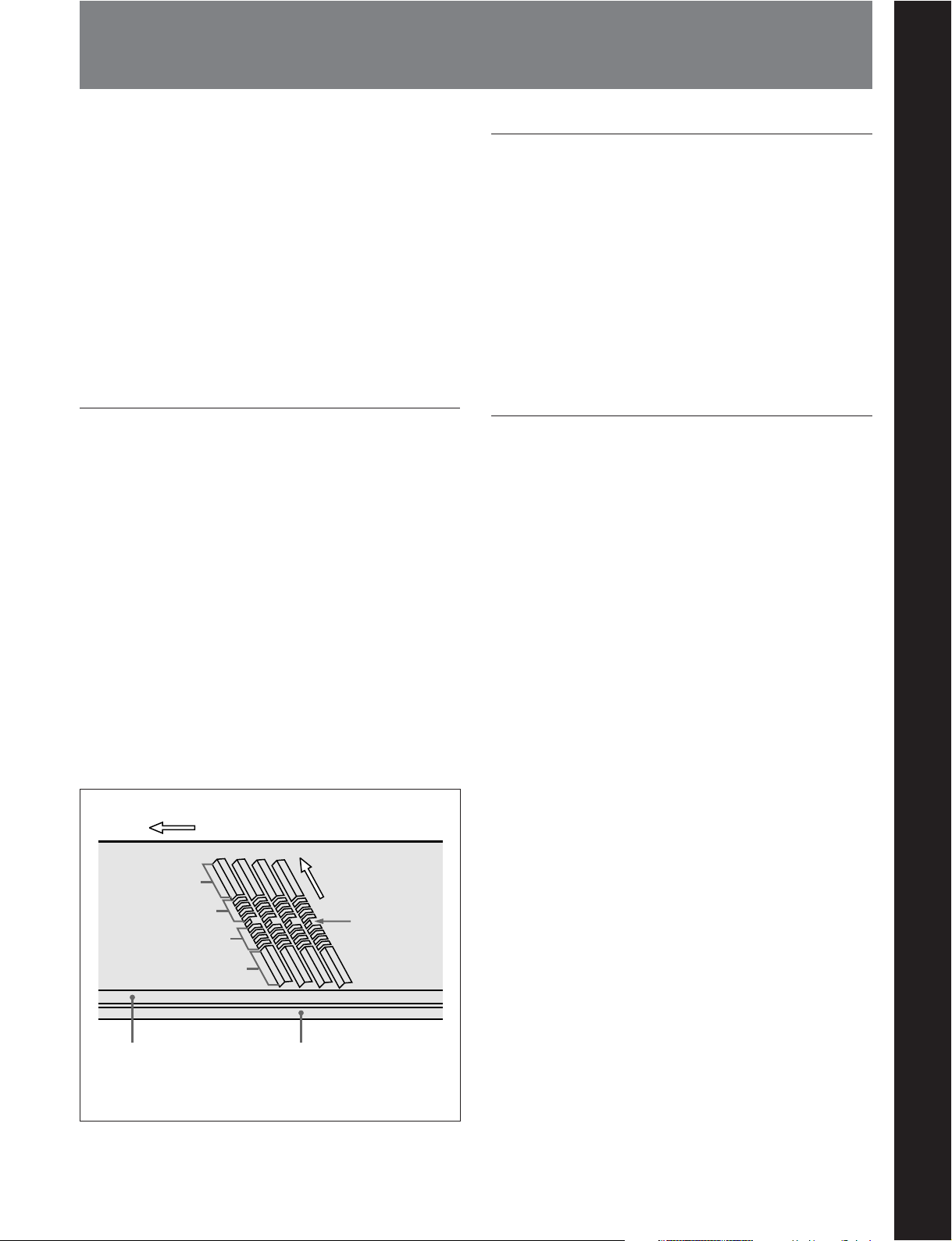
MPEG IMX format
The MPEG IMX format uses the same 12.65-mm
width tape as the conventional Betacam series. This
economical format uses 50 Mbps high image quality
MPEG-2 compression, and offers up to three hours of
recording.
The video signal compression, as in the Betacam SX
format, uses MPEG-2, and compressed data can be
passed directly without loss of quality, not only to
VTRs, but also to other devices with MPEG support,
such as nonlinear editors or servers. There is thus high
compatibility with the next generation of digital
television formats supporting MPEG-2.
The audio tracks allow up to eight channels to be
recorded, and this also provides future extensibility for
multichannel, multilingual broadcasting, data
broadcasting, and so on.
Direction of tape travel
Direction of head
Video
Audio
Audio
motion
SAT
a)
High-performance heads and compatibility
playback function
Chapter 1 Overview
The newly developed high-performance heads and
dynamic tracking (DT) technology provide highdensity playback in narrow tracks with high reliability.
In addition to the MPEG IMX playback heads, this
unit is also equipped with Betacam SX format
playback heads, and analog Betacam DT heads, to
provide compatibility playback functions, and
allowing a wide variety of recorded resources to be
used effectively.
High-precision digital signal processing
and range of interfaces
The MPEG IMX VTR digital video signal processing
uses 4:2:2 component video signals complying with
ITU-R Rec 601/SMPTE 259M, which are compressed
with ISO/IEC 13818-2000 MPEG-2 compression.
While supporting a wide range of signals for output,
all of the VTR internal processing is digital, providing
high stability and reliability.
The audio signals, similarly, are based on AES/EBU
format, and are subjected to digital signal processing
while still uncompressed.
The following interfaces are standard equipment, for
ease of connection to different external devices.
•Analog composite signal input/output
•Analog component signal output
•Analog audio signal output (4 channels)
• Serial Digital Interface SMPTE 259M output
(component digital video/audio, 8 channels)
•AES/EBU serial digital audio output (8 channels)
•SDTI-CP SMPTE 326M output (MPEG video/audio
data)
• Time code output
Video
Control (CTL) track
a) Supplemental Automatic Tracking signal
Time code track
Chapter 1 Overview 1-1

1-1 Features
Chapter Overview
Network interface function (MSW-M2100E/
M2100EP only)
The MSW-M2100E/M2100EP is equipped with an
Ethernet
a 10/100/1000Base-T network to transfer video, audio,
and metadata as MXF files. MXF (Material Exchange
Format) is a file format that stores video, audio, and
metadata in a single package. It enables
communication between network devices such as
VTRs and servers.
a) Ethernet is a trademark of Xerox Corporation.
a)
connector, enabling the VTR to be added to
High image quality MPEG-2 intraframe
encoding at 50 Mbps.
The video signal compression uses MPEG-2
intraframe encoding conforming to 4:2:2 Profile @
Main Level, with a 1:3.3 compression ratio; the data is
then recorded with a bit rate of 50 Mbps. With the
highly efficient MPEG-2 compression, the image
quality is high enough to withstand a range of editing
and dubbing operations.
The recorded MPEG-2 data can be passed directly to
other nonlinear systems, allowing optimum editing
with no loss of image quality.
High quality eight-channel audio
High quality 16 bit/48 kHz digital audio is supported.
There are eight digital audio output channels, and four
analog audio output channels.
To support even higher quality playback, there is a
four-channel mode using 24 bit/48 kHz encoding.
Thus this unit is eminently suitable not only for
multichannel applications, but also for high quality
audio editing.
Playback of SDTI compressed data
This unit is fitted with SDTI-CP output complying
with SMPTE 326M, and can therefore be used for
transferring MPEG-2 data, audio data, metadata, and
so on to a VTR or nonlinear device.
Newly developed multifunction control
panel
While a compact 4U size, this unit has a front panel
which provides a wide range of functions while
maintaining existing operability.
Basic operation buttons and jog/shuttle
dial
The basic buttons and jog/shuttle dial for VTR and
editing operations are provided in the conventional
VTR layout, ensuring continuity with conventional
operating panels.
Time data display
This can be selected to display a CTL counter value,
time code value, or time code user bits. It can also
display edit points and edit durations.
Menu-based control interface
The time data/menu display shows not only various
values and settings, but also the pages of a menu
system for commonly used functions. You can use the
function keys and MULTI CONTROL knob to easily
change settings.
Other operation settings, including interfacing with
external devices, can be set from the control panel by
the same type of setup menu system as on a
conventional VTR.
Eight-channel audio level meters
The unit has independent audio level meters and
playback level controls for all eight channels. The
level meters are on the control panel, so that when the
panel is used remotely from the main unit it is still
easy to check or adjust the audio levels.
1-2 Chapter 1 Overview

High quality variable speed playback and
digital jog sound function
In digital BETACAM or MPEG IMX format playback,
the dedicated playback DT heads allow smooth,
noiseless playback from –1 to +3 times normal speed.
In analog Betacam compatible playback also, similar
dedicated DT heads allow noiseless playback from –1
to +3 times normal speed, and in Betacam SX format
compatible playback, special multi-head playback
technology allows noiseless playback from –1 to +2
times normal speed.
In slow motion operation, the digital jog sound
function provides the same ease of operation as a
conventional analog VTR.
Wide range of editing functions
Using this unit in combination with a recorder, you can
carry out both assemble editing and insert editing
automatically. All of the necessary editing functions
are provided to set and amend edit points, to preview
and review results of editing, and so on.
Rack mounting
Using the optional RMM-131 Rack Mount Adaptor,
you can mount the unit in a standard EIA 19-inch rack.
For details of rack mounting, refer to the Installation
Manual.
Chapter 1 Overview
DMC playback
This allows automatic playback with a varying speed
memorized beforehand for the desired segment.
Tele-File functions
Tele-File enables data writing/reading between
cassettes with memory labels and VTRs. It increases
the efficiency of operations such as cuing up and
playback, and source data management.
Remote control function
This unit can be controlled from an external remote
controller or editor through an interface complying
with RS-422A (serial 9-pin). Since two remote control
connectors are provided, you can also control a
number of VTRs simultaneously.
Additionally, a parallel (50-pin) interface is also fitted
as standard, supporting easy external control through
the parallel interface.
Chapter 1 Overview 1-3
Chapter Overview
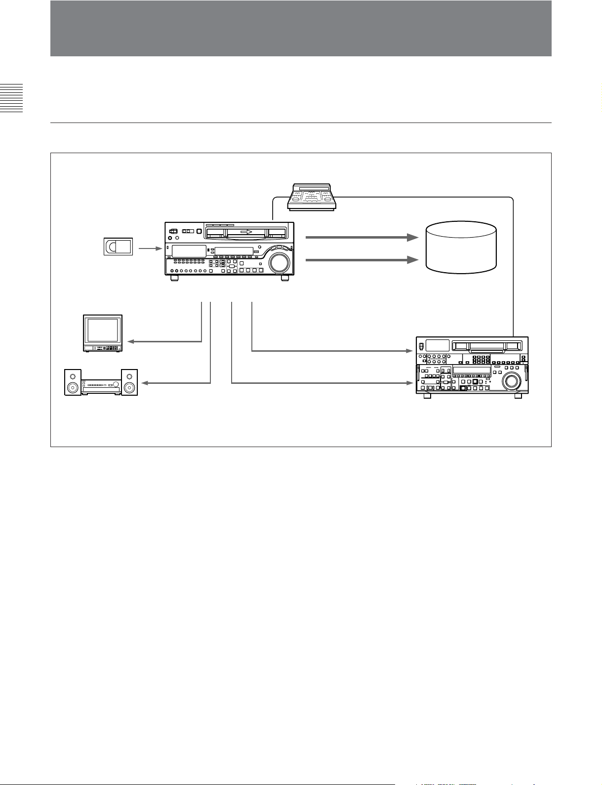
1-2 Example System Configuration
1-1 Features
The following conceptual diagrams show examples of
use.
Basic System
BVE-series editor
Tape control
Digital/analog cassette
Video monitor
Analog composite
Audio monitor
MSW-M2100/M2100P
Analog audio
SDTI-CP
SDI
Analog composite/component
SDI
Audio/video
server
system
VTR with SDTI/SDI
connectors or analog VTR
1-4 Chapter 1 Overview
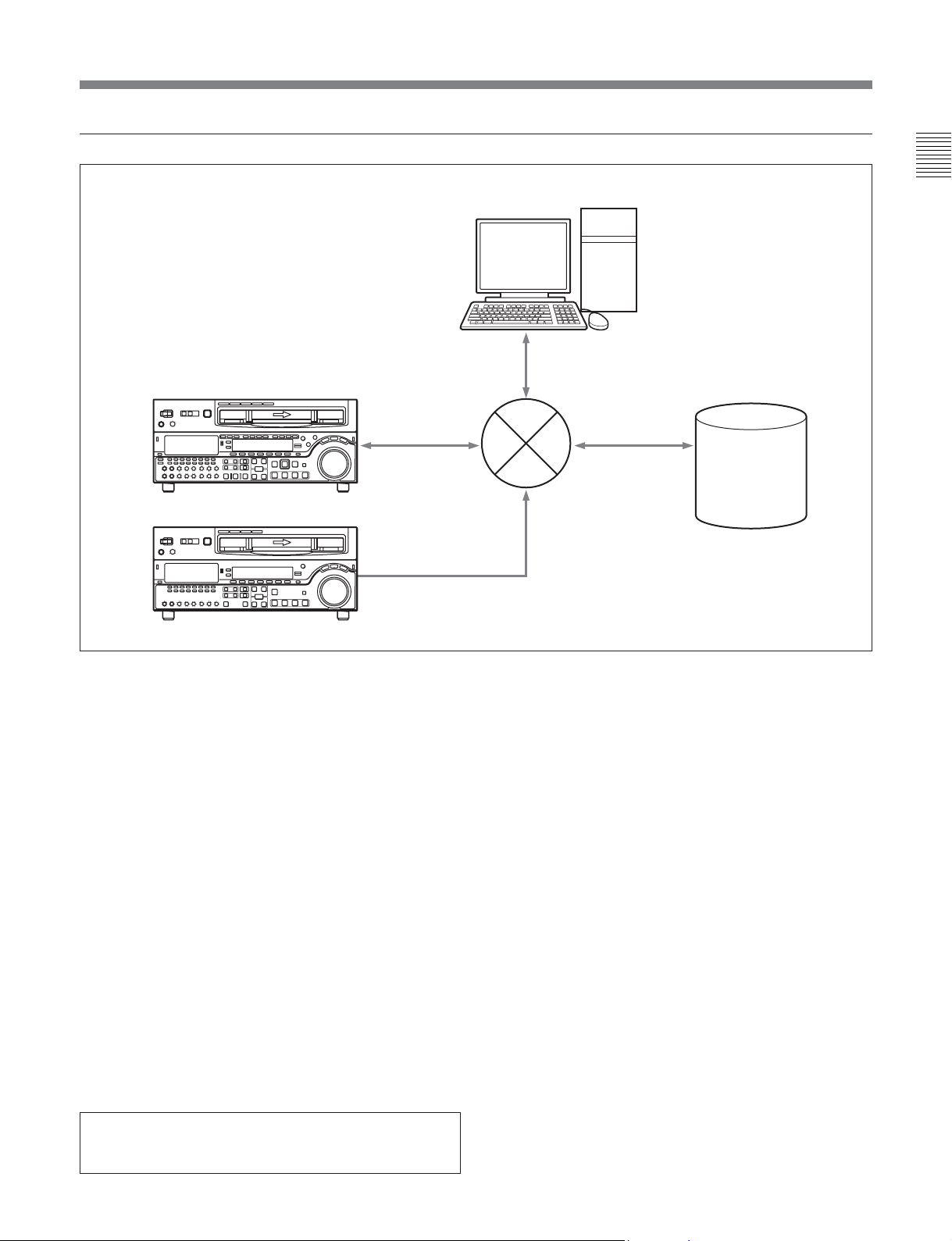
Network System
MSW-M2000E/M2000EP
MSW-M2100E/M2100EP
MXF files
MXF files
Control
PC
Chapter 1 Overview
Network (Eternet)
MXF files
Audio/Video
server
system
Using the Application Software (for users of the MSW-M2100E/M2100EP)
By installing the supplied application software “e-VTR
Manager” on a PC, you can control the VTR from the
PC.
System requirements
The following are required for the PC on which e-VTR
To install the software
1 Insert the CD-ROM in the drive of your PC and
double-click on Setup.exe.
2 Perform the installation, following the instructions
of the Wizard.
Manager is to be installed. If these requirements are
not met, e-VTR Manager may not operate properly.
To start e-VTR Manager
Double-click on the e-VTR Manager icon on the
CPU: 1 GHz or higher
desktop.
Memory: 256 MB or greater
OS: Windows XP/2000
DirectX 8.1b or higher
For details, refer to the BKMW-E3000 Operation Manual
contained on the enclosed CD-ROM.
Language: English
Available hard disk space: 5 MB or more
Monitor resolution: XGA (1024×768) or more
recommended
Microsoft and Windows are registered trademarks of
Microsoft Corporation in the United States and/or other
countries.
Chapter 1 Overview 1-5

1-1 Features
1-3 MPEG-4 Visual Patent Portfolio License
Model: MSW-M2100E/M2100EP
Chapter Overview
This product is licensed under the MPEG-4 Visual
Patent Portfolio License. For the personal and
noncommercial use of a consumer for (i) encoding
video in compliance with the MPEG-4 Visual Standard
(“MPEG-4 Video”) and/or (ii) decoding MPEG-4
Video that was encoded by a consumer engaged in a
personal and non-commercial activity and/or was
obtained from a video provider licensed by MPEG LA
to provide MPEG-4 Video.
No license is granted or shall be implied for any other
use.
Additional information including that relating to
promotional, internal and commercial uses and
licensing may be obtained from MPEG LA, LLC.
See http://www.mpegla.com
1-4 MPEG-2 Video Patent Portfolio License 1-3 MPEG-4 Visual Patent Portfolio License
ANY USE OF THIS PRODUCT OTHER THAN
CONSUMER PERSONAL USE IN ANY MANNER
THAT COMPLIES WITH THE MPEG-2
STANDARD FOR ENCODING VIDEO
INFORMATION FOR PACKAGED MEDIA IS
EXPRESSLY PROHIBITED WITHOUT A LICENSE
UNDER APPLICABLE PATENTS IN THE MPEG-2
PATENT PORTFOLIO, WHICH LICENSE IS
AVAILABLE FROM MPEG LA, L.L.C., 250
STEELE STREET, SUITE 300, DENVER,
COLORADO 80206.
“PACKAGED MEDIA” means any storage media
storing MPEG-2 video information such as DVD
movie which are sold/distributed to general consumers.
Disc replicators or sellers of the PACKAGED MEDIA
need to obtain licenses for their own business from
MPEG LA. Please contact MPEG LA for any further
information. MPEG LA. L.L.C., 250 STEELE
STREET, SUITE 300, DENVER, COLORADO 80206
http://www.mpegla.com
1-6 Chapter 1 Overview
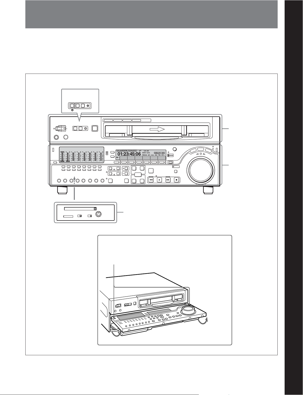
2-1 Control Panels
There are three control panels, as follows:
•Upper control panel
• Lower control panel
•Switch panel
Chapter 2 Location and Function of Parts
MSW-M2100E/M2100EP
REMOTE
NEWORK 1 (9P) 2 (50P) RS-232C
Z
KEY INHI
PANE L SEL
OFF
FRONTREAR
ON
CONTROL PANEL
Chapter 2 Location and Function of Parts
MSW-M2100/M2100P
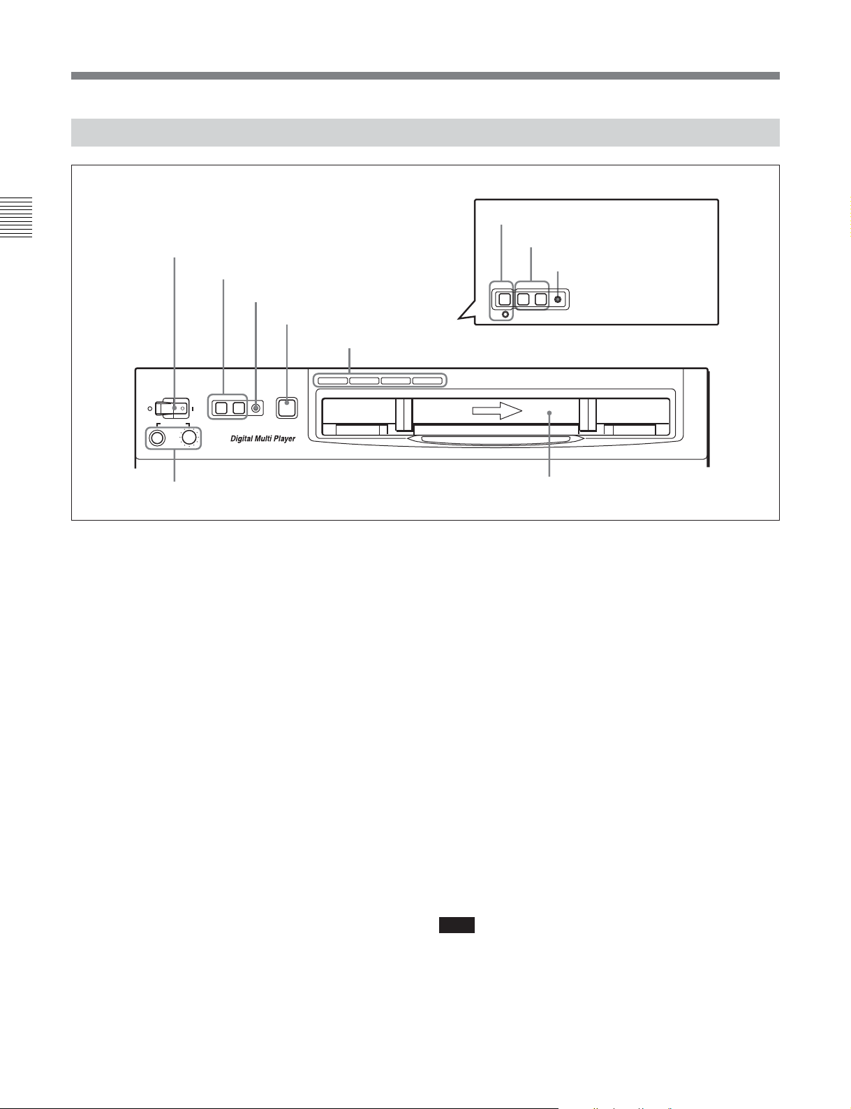
Upper control panel
(see page 2-2)
CTL/TCTCMENU
Lower control panel
(see page 2-4)
Switch panel (access by opening the lower control panel)
(see page 2-13)
Lower control panel unlock buttons
Pushing in these buttons allows you to open the lower control panel.
Chapter 2 Location and Function of Parts 2-1
2-1 Control Panels
2-1-1 Upper Control Panel
Chapter 2 Location and Function of Parts
1 POWER switch
3 REMOTE buttons
POWER
PHONES
REMOTE
1(9P) 2(50P) RS-232C
4 RS-232C indicator
5 EJECT button
6 Format indicators
BETACAM/SP
EJECT
Z
BETACAM SX MPEG IMX
Digital BETACAM
MSW-M2100E/M2100EP
2 NETWORK button and indicator
3 REMOTE buttons
4 RS-232C indicator
REMOTE
NEWORK 1 (9P) 2 (50P) RS-232C
MSW-M2100/M2100P
7 PHONES jack and control
1 POWER switch
Pressing the ‘ ) ’ side of the switch powers the unit on.
When the unit is powered on, the audio setting display
section (see page 2-5) and the time data/menu display
section (see page 2-7) light.
2 NETWORK (network enable) button and
indicator (MSW-M2100E/M2100EP only)
The VTR can send MXF files containing video, audio
and metadata to devices connected via the RJ-45
network. When you press the button, it lights up.
Even when the button is off, web and SNMP
communications are enabled. When you press and
light the button, the REMOTE 1(9P) and 2 (50P)
buttons go dark.
When the VTR is connected by using RJ-45 control,
the NETWORK indicator lights.
The NETWORK indicator flashes during data
connection (MXF file transmission).
For details on the network functions using the NETWORK
button, refer to the Operation Manual of the BKMW-E3000
Network Interface Board.
Cassette compartment
3 REMOTE buttons
Press one of these buttons to select the device
controlling this unit.
1(9P): This unit is controlled by the device connected
to the REMOTE 1-IN(9P) or REMOTE 1OUT(9P) connector. The button lights.
2(50P): This unit is controlled by the device
connected to the REMOTE 2 PARALLEL I/
O(50P) connector. The button lights.
4 RS-232C indicator
This indicator lights when this unit is controlled
through the RS-232C connector.
5 EJECT button
To eject the cassette, press this button. While the
cassette is being ejected, this button lights.
When using the lower control panel as remote control
panel, press the DELETE button and STOP button at
the same time to eject the cassette.
Note
Ejecting with the EJECT button is a local operation. It
is not possible to eject a cassette in another unit by
remote control.
2-2 Chapter 2 Location and Function of Parts

6 Format indicators
The BETACAM/SP, BETACAM SX, MPEG IMX, or
Digital BETACAM indicator lights depending on the
current playback format.
The BETACAM/SP indicator lights when the format is
Betacam or Betacam SP.
7 PHONES jack and control
Connect stereo headphones with an impedance of
8 ohms to monitor the sound during playback.
The control knob adjusts the volume.
It is possible to set an internal board switch so that the
output volume from the MONITOR OUTPUT L and R
connectors is controlled simultaneously.
For details, refer to the Installation Manual.
Chapter 2 Location and Function of Parts
Chapter 2 Location and Function of Parts 2-3
2-1 Control Panels
2-1-2 Lower Control Panel
Chapter 2 Location and Function of Parts
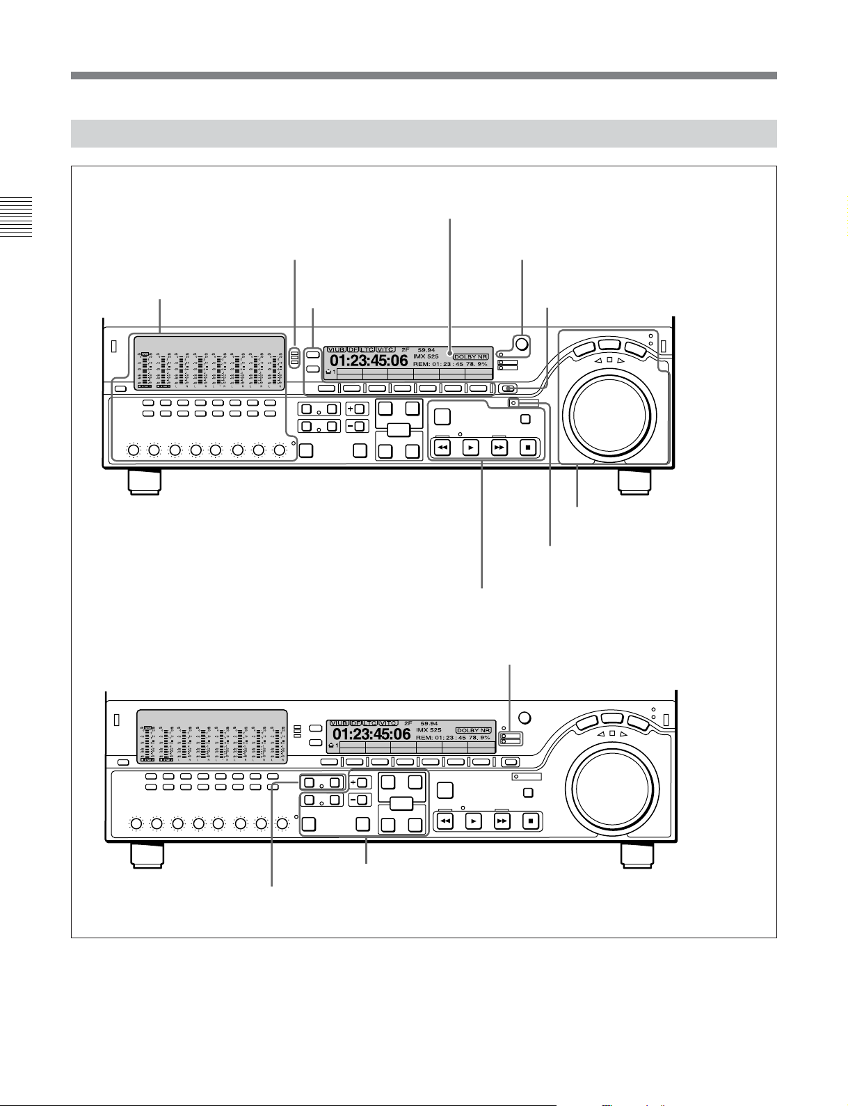
2 CHANNEL CONDITION
indicator
(see page 2-6)
4 Time data/menu display section
(see page 2-7)
5 MULTI CONTROL knob and SHIFT indicator
(see page 2-8)
1 Audio control section
(see page 2-5)
3 Menu control buttons
(see page 2-6)
CTL/TC
TC
6 RESET button
MENU
8 GOOD SHOT REC INHI indicator
9 Tape transport control section
(see page 2-10)
q; ALARM indicator and KEY INHI
indicator
(see page 2-8)
7 Search control section
(see page 2-8)
(see page 2-10)
(see page 2-11)
qs Shot mark section
(see page 2-12)
2-4 Chapter 2 Location and Function of Parts
MENU
CTL/TC
TC
qa DMC playback control section
(see page 2-11)
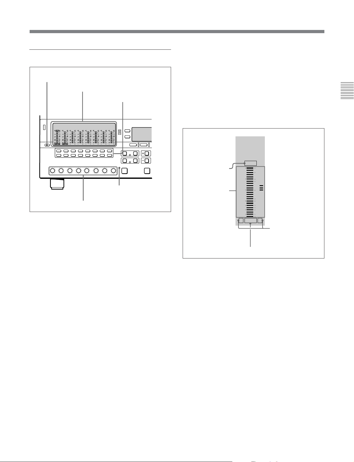
1 Audio control section
1 DISPLAY FULL/FINE button
2 Audio setting display section
3 Audio signal
selection buttons
5 ALL CH indicator
4 PB controls
In the audio control section, you can select and display
output signals for audio channels 1 to 8.
In playback mode, the display changes to the channel
setting indication depending on the number of the
output channels of the audio test signal generator.
FINE: The display is enlarged, with a step of
0.25 dB. A segment indicating the reference level
lights. In this mode only the segment of the
display corresponding to the current audio level
lights. If the audio level exceeds the maximum
display level, the top segment flashes, and if the
audio level goes below the minimum display
level, the bottom segment flashes.
2 Audio setting display section
OVER
OVER indicator
Level meter
dB dB
-10
-20
-30
-40
-60
L R
20
0
2
10
1
0
-1
-10
-20
-2
-40
EMPH
EMPH indicator
Monitor channel L
and R indicators
Chapter 2 Location and Function of Parts
Changing the number of the channels of the audio test
signal generator is performed using the Maintenance
menu.
For details on the Maintenance menu, refer to the
Maintenance Manual, Volume 1.
When a digital Betacam tape is played back, the digital
audio levels are displayed on the level meters for
channels 1 to 4 in the audio setting display section 2.
The level meter for channel 7 displays the cue audio
level always in FULL mode (see the description of the
DISPLAY FULL/FINE button 1).
1 DISPLAY FULL/FINE button
Pressing this button toggles the display mode of the
level meters in the audio setting display section
between FULL and FINE.
FULL: The display covers the range –60 dB to 0 dB
or –40 dB to +20 dB as selected using setup menu
item 806. In this mode the segment of the display
corresponding to the current audio level and all
lower segments light.
OVER indicator: While the unit is in playback
mode, this lights when the level of the audio
signal on the corresponding channel exceeds the
maximum level that can be indicated on the level
meter.
Level meter: Displays the audio signal level when
the unit is in playback mode. You can use the
setup menu to switch the display mode between
PEAK.0 (0 dB is maximum level) and REF.0
(0 dB is the reference level). You can also use the
DISPLAY FULL/FINE button 1 to enlarge the
display only near the reference level.
When a digital Betacam tape is played back, the
level meter for channel 7 displays the cue audio
level.
Monitor channel L and R indicators: Indicate
whether or not the signals of the track are output
to the MONITOR OUTPUT L and R connectors
or the PHONES jack. ‘L’ lights to indicate output
to the left monitor channel, and ‘R’ lights to
indicate output to the right monitor channel.
Chapter 2 Location and Function of Parts 2-5

2-1 Control Panels
EMPH (emphasis) indicator: During playback, this
lights when the emphasis setting is on for the
audio signal on the corresponding track.
3 Audio signal selection buttons (CH1 to CH8)
The buttons in the upper and lower rows select tracks
Chapter 2 Location and Function of Parts
to be output to the MONITOR OUTPUT L and R
connectors on the connector panel or the PHONES
jack on the upper control panel. The buttons in the
upper row (L row) select tracks for output to the
MONITOR OUTPUT L connector, and the buttons on
the lower row (R row) select tracks for output to the
MONITOR OUTPUT R connector. You can obtain the
mixed output of multiple tracks by simultaneously
pressing multiple buttons in the upper or lower rows.
For example, simultaneously press the CH1, CH2, and
CH3 buttons in the upper row to mix the signals of
audio tracks 1, 2, and 3 for output to the MONITOR
OUTPUT L connector.
4 PB (playback) controls
These adjust individually the playback levels on
channels 1 to 8.
During playback, press to protrude the control knobs
and adjust the level while monitoring the audio level
indication on the level meters in the audio setting
display section.
When the control knobs are pushed in, the playback
levels return to the preset levels, and cannot be
adjusted.
When playing back a digital Betacam tape, you can use
the control knob for channel 7 to adjust the cue audio
playback level.
About the CH8/ALL CH (channels) control
You can choose to use the rightmost CH8/ALL CH
control to adjust the playback level of all channels.
This setting is made in setup menu item 132. When
adjustment by the CH8/ALL CH control is enabled,
the CH1 to CH7 controls are disabled.
5 ALL CH (channels) indicator
This indicator lights when adjustment of all audio
channels by the rightmost PB control (CH8/ALL CH)
is selected.
2 CHANNEL CONDITION indicator
A three-color indicator shows the state of the playback
signal.
Green: The state of the playback signal is good.
Yellow: The playback signal is somewhat
deteriorated, but playback is possible.
Red: The playback signal is deteriorated.
When this indicator remains on, head cleaning or
an internal inspection is necessary.
Note
During analog playback, indications are by green and
red only.
3 Menu control buttons
These buttons are used for function menu (see the
following section “Overview of the function menu”)
and setup menu (see Chapter 11) operations. The page
buttons (V, v, and HOME) select menu pages, and the
function buttons (F1 to F6) make function settings.
V: Selects the next page in the order HOME t 1 t
2 t 3 t 4 t 5 t 6 t HOME.
v: Selects the next page in the order HOME t 6 t
5 t 4 t 3 t 2 t 1 t HOME.
When there are setup menu definitions on page 6,
page 6 is displayed between page 5 and the HOME
page.
HOME: Selects the function menu HOME page.
When at least one user-defined function key is set
in the HOME2 page, pressing the HOME button
toggles the menu page display between HOME
and HOME2.
F1 to F6: Make settings for the items displayed in the
upper line of the menu display (the menu item
display line). Pressing one of these buttons
changes the setting for the corresponding item and
displays the setting in the lower line of the menu
display.
If there is no setting displayed in the lower line of
the menu display, even though a menu item is
displayed in the upper line, pressing the
corresponding function button moves to a lower
menu level.
2-6 Chapter 2 Location and Function of Parts
Overview of the function menu
The function menu provides convenient access to
frequently used function settings, such as video signal
output level and time code settings.
For details on the function menu, see Chapter 10.
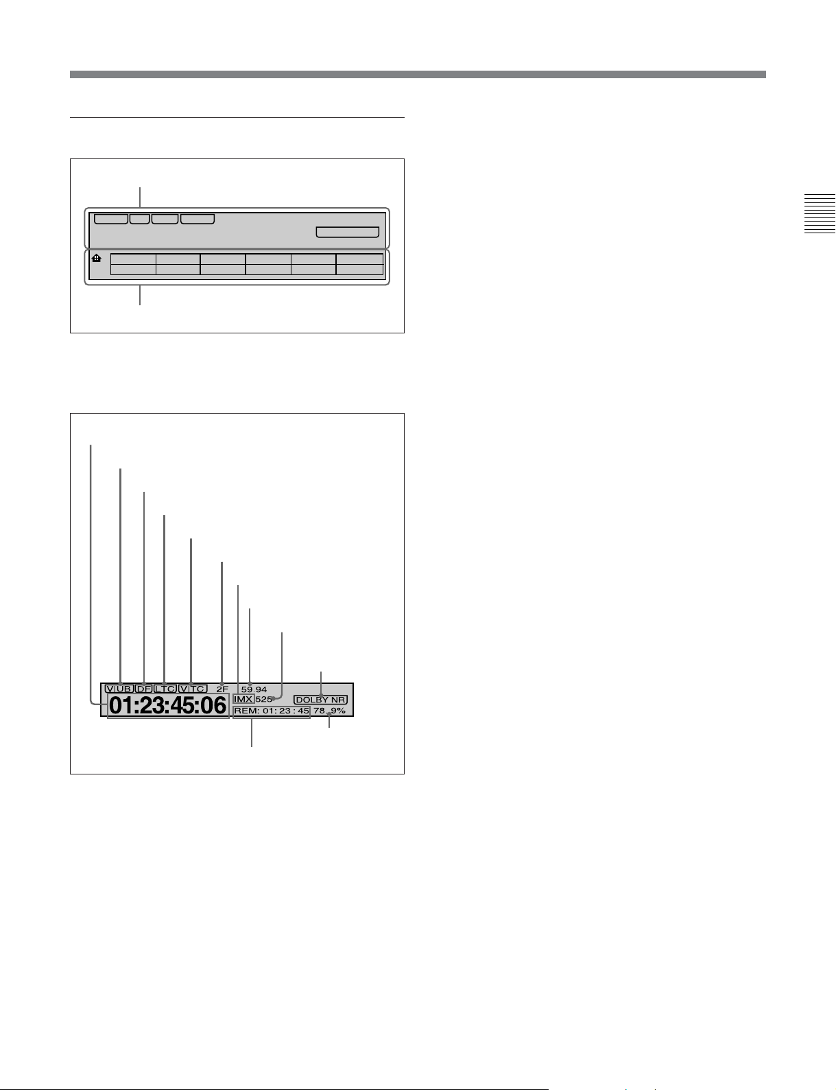
4 Time data/menu display section
1 Time data display
VIUB VITC
DF LTC
01: : :23 45 06
1
2 Menu display
1 Time data display
This displays indicators relating to time data and other
indicators.
2F 59.94
IMX 525
REM: 01: 23 : 45 78. 9%
CTL/TCTCMENU
DOLBY NR
DF (drop-frame) indicator (525-line mode only)
This lights when values of drop-frame mode time code
are displayed.
LTC indicator
Regardless of the display in time data display
area 1, this indicator lights when LTC values are being
read.
VITC indicator
Regardless of the display in time data display
area 1, this indicator lights when VITC values are
being read.
Capstan lock mode indicator
This indicates the capstan lock mode (2F, 4F, or 8F)
set in function menu page 4 or in setup menu item 106.
Chapter 2 Location and Function of Parts
Time data display area 1
Time data type indicator
DF indicator
LTC indicator
VITC indicator
Capstan lock mode indicator
Playback format indicator
System frequency indicator
525/625 indicator
DOLBY NR indicator
Speed indication area
Time data display area 2
Time data display area 1
Normally this displays a CTL count, time code value,
or user bit value according to the setting in function
menu HOME page for F4 (CTL/TC).
Time data type indicator
This indicates the type of data displayed in the time
data display area 1.
LTC (longitudinal time code): Time code recorded
on a longitudinal track on the tape
LUB: LTC user bit values
VITC (vertical interval time code): Time code
recorded in the vertical blanking interval
VIUB: VITC user bit value
Playback format indicator
This indicator shows the current playback format.
DB: Digital BETACAM format
IMX: MPEG IMX format, bit rate 50 Mbps, 8 audio
channels
IMX4: MPEG IMX format, bit rate 50 Mbps, 4 audio
channels
SX: Betacam SX format
SP: Betacam SP format
No display: Betacam format
System frequency indicator
Displays the current playback field frequency, and the
bit rate of recording or SDTI-CP output.
525/625 indicator
This indicator shows the number of scan lines for the
television standard (525 (NTSC) or 625 (PAL))
selected using setup menu item 013.
Time data display area 2
Displays data types and time data such as the time
code of edit points and the total time of that tape.
The following data types are shown.
TOTL: Total time of the tape
REM: Remaining time on the tape
Depending on the setting of F5 (T INFO) on function
menu page 3, either TOTL (TOTAL) or REM
(REMAIN) is displayed.
The values displayed are approximate values
calculated on the basis of the detected tape diameter.
They are not precise to units of seconds.
Chapter 2 Location and Function of Parts 2-7
2-1 Control Panels
BOT: Returned to top of tape
EOT: Reached end of tape
IN: video IN point
OUT: video OUT point
AIN: audio IN point
Chapter 2 Location and Function of Parts
AOUT: audio OUT point
DUR: duration value
DOLBY NR indicator
This lights when the Dolby noise-reduction
functioning.
Speed indication area
This indicates the speed of a DMC playback.
In the time data display area 2, “DMC SPD” is
displayed during a DMC playback.
2 Menu display
This displays the function menu and setup menu.
For details on the function menu, see Chapter 10 and for
details on the setup menu, see Chapter 11.
1)
circuit is
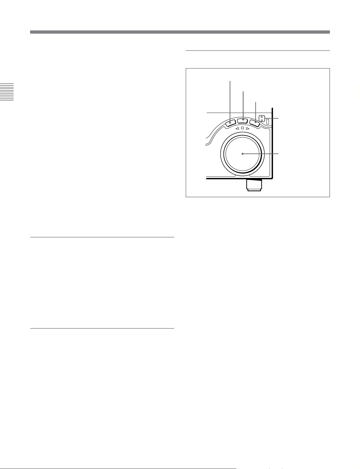
7 Search control section
1 SHUTTLE button
2 JOG button
3 VAR button
SHUTTLE/VAR
SHUTTLE
V
E
R
JOG
E
S
R
E
VAR
FORWARD
JOG
1 SHUTTLE button
To use the search dial for playback in shuttle mode,
press this button, turning it on.
4 SHUTTLE/VAR
and JOG
indicators
5 Search dial
5 MULTI CONTROL knob and SHIFT
For details of playback in shuttle mode, see the description
of the search dial 5.
indicator
2 JOG button
In function menu operations, rotate the MULTI
CONTROL knob to change settings that flash in the
To use the search dial for playback in jog mode, press
this button, turning it on.
menu display section. In setup menu operations, rotate
this knob to select menu items.
The SHIFT indicator lights when you press this knob
For details of playback in jog mode, see the description of
the search dial 5.
in. In this state, the value of the setting changes by a
greater amount when you rotate the knob.
3 VAR (variable) button
To use the search dial for playback in variable speed
mode, press this button, turning it on.
6 RESET button
For details of playback in variable speed mode, see the
To reset the CTL value displayed in time data display
area 1, press this button.
Resetting the CTL value erases all edit points.
..........................................................................................................................................................................................................
description of the search dial 5.
1) Dolby noise reduction: Dolby noise reduction
manufactured under license from Dolby Laboratories
Licensing Corporation. “DOLBY” and the double-D
symbol ; are trademarks of Dolby Laboratories
Licensing Corporation.
2-8 Chapter 2 Location and Function of Parts

4 SHUTTLE/VAR and JOG indicators
Either of the indicators is lit to show the current search
mode or the mode used last. When the unit is turned
on, the SHUTTLE/VAR indicator lights.
When the SHUTTLE/VAR indicator is lit: Shuttle
or variable speed mode
When the JOG indicator is lit: Jog mode
5 Search dial
Turn this to carry out playback in the modes shown in
the following table. Turning the dial clockwise lights
the H indicator and plays back in the forward
direction. Turning the dial counterclockwise lights the
h indicator and plays back in the reverse direction.
When the tape is stopped or the unit is turned on, the
s indicator lights. Pressing the dial toggles between
shuttle and jog modes or between variable speed and
jog modes.
You can carry out noiseless playback in the following
speed ranges depending on the tape format.
Digital Betacam: –1 to +3 times normal speed
MPEG IMX: –1 to +3 times normal speed
Betacam SX: –1 to +2 times normal speed
Betacam/Betacam SP: –1 to +3 times normal speed
Playback modes using the search dial
Playback mode
Shuttle
Jog Press the JOG button or the search
Variable speed Press the VAR button, turning it on,
Capstan override
Operations and functions
Press the SHUTTLE button or the
search dial so that the SHUTTLE
button lights, then turn the search dial.
Playback is carried out at a speed
determined by the position of the
search dial. The playback speed
range is as follows:
• Using a Digital Betacam tape: ±50
times normal speed
• Using an MPEG IMX tape: ±78
times normal speed
• Using a Betacam SX tape: ±78
times normal speed
• Using an analog Betacam tape: ±35
times normal speed for 525/60 mode
or ±42 times normal speed for 625/
50 mode
The search dial has detents at the still
position and at ±5 times normal
speed.
The maximum shuttle mode playback
speed can be changed by changing
the setting of setup menu item 102
(see page 11-8)
dial so that the JOG button lights, then
turn the search dial. Playback is
carried out at a speed determined by
the speed of rotation of the search
dial. The playback speed range is ±1
time normal speed.
The search dial has no detents.
then turn the search dial. You can
control the playback speed finely (a
maximum of 51 steps) in the range in
which noiseless playback is possible.
The search dial has detents at the still
position and at the normal speed
position.
For details on operation, see page
4-5.
.
Chapter 2 Location and Function of Parts
Setting setup menu item 101 (see page 11-8) to KEY enables
you to use only the SHUTTLE, JOG, and VAR buttons to
select shuttle/jog/variable speed modes.
Chapter 2 Location and Function of Parts 2-9
2-1 Control Panels
8 GOOD SHOT REC INHI (shot mark
recording inhibit) indicator
This indicator is on or off according to the
combination of the F5 (RECINH) setting on function
menu page 4 and the record inhibit plug on the
Chapter 2 Location and Function of Parts
cassette, as shown in the following table. When this
indicator is on, writing shot marks on tape is
prohibited.
GOOD SHOT REC INHI indicator indications
RECINH setting
ON
OFF Record inhibit Lit
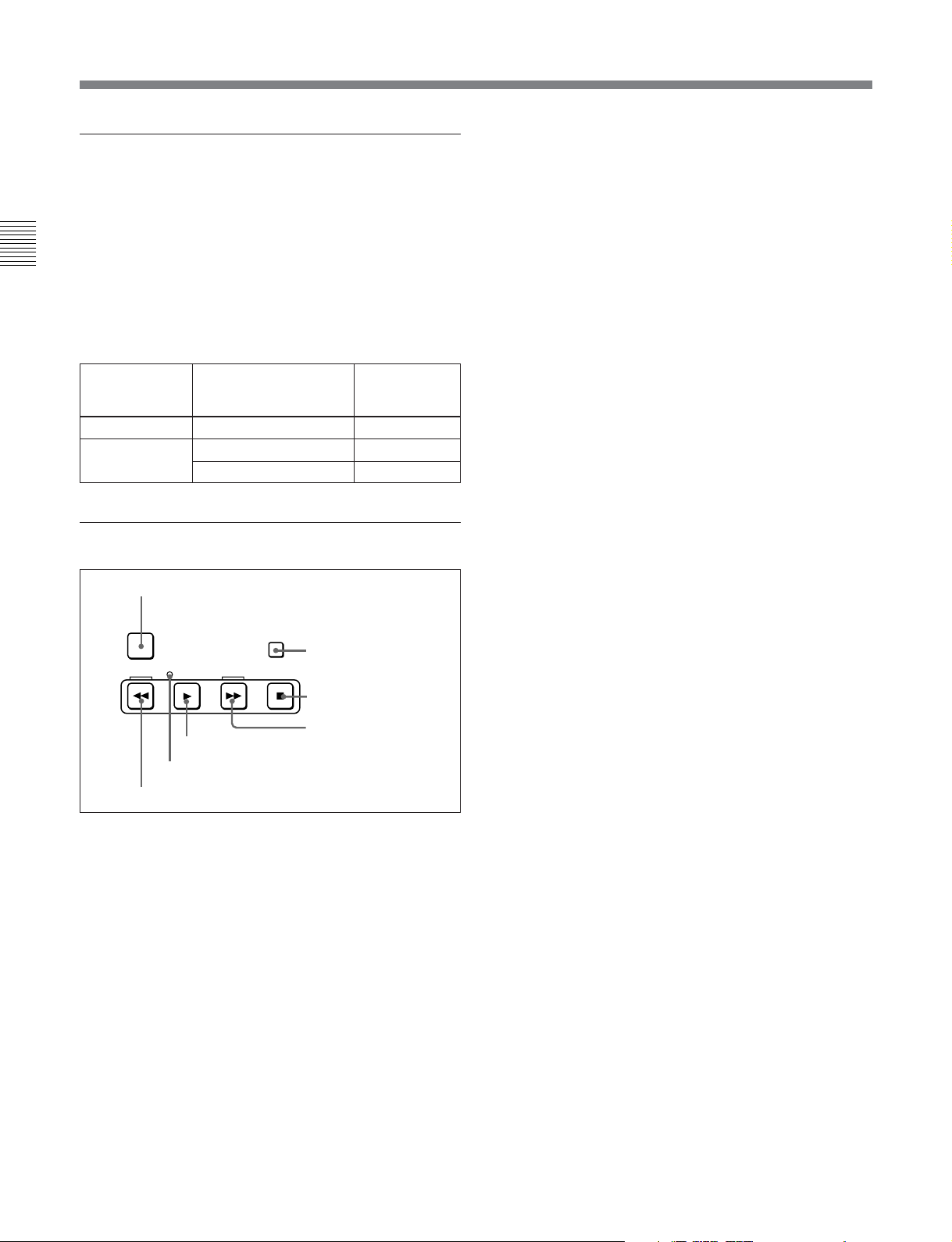
9 Tape transport control section
1 PREROLL button
PREROLL
REW
6 SERVO indicator
7 REW button
1 PREROLL button
Press this button to cue up to the preroll point (before
the IN point by the time set as the preroll time) on the
tape. You can change or select the preroll time and the
state of the unit at the end of preroll (“stop mode”
still playback mode) using setup menu item 001 or
401.
State of the record
inhibit plug on the
cassette
Record inhibit/permit Lit
Record permit
STANDBY
2 STANDBY button
F FWD
PLAY
5 PLAY button
STOP
3 STOP button
4 F FWD button
GOOD SHOT
REC INHI
indicator state
Off
1)
or
2 STANDBY button
When a cassette is inserted and this button is off, to put
the unit in standby mode, press the button, turning it
on.
In standby mode, the drum is rotating and the tape is in
contact with the drum. As a result, playback can start
immediately.
To end standby mode, press the STANDBY button,
turning it off.
If 8 minutes (value can be varied using setup menu
item 501) elapse in standby mode, the unit
automatically switches out of standby mode to protect
the tape.
3 STOP button
To stop playback, press this button, turning it on.
When you stop playback, the unit switches to still
playback.
On the MSW-M2100E/M2100EP, press and light the
button to stop file transmission to the network.
Fault display function
The STOP button flashes when there is no external
reference signal input or the input external reference
signal is not synchronized to the input video signal.
4 F FWD (fast forward) button
To fast forward the tape, press this button, turning it
on.
5 PLAY button
To start playback, press this button, turning it on.
To operate in capstan override mode
Hold down this button, and turn the search dial.
For details of capstan override mode, see page 4-5.
6 SERVO indicator
Lights when the drum servo and capstan servo are
locked.
Cuing up to DMC playback control points
Hold down the STUNT IN, STUNT OUT, PLAY IN,
7 REW (rewind) button
To rewind the tape, press this button, turning it on.
or PLAY OUT button while pressing this button to cue
up to the corresponding DMC playback control point.
..........................................................................................................................................................................................................
1) Stop mode: The state in which the device currently the
subject of operation is stopped, and the STOP button is
lit.
2-10 Chapter 2 Location and Function of Parts

q; ALARM indicator and KEY INHI
indicator
ALARM indicator
This lights when a hardware error is detected on the
unit, and goes off when the error is resolved.
When this indicator is lit, an error message appears in
the time data/menu display section. If you are using the
SDI OUTPUT 3(SUPER) or COMPOSITE VIDEO
OUTPUT 3(SUPER) connector, then when the setting
of F4 (CHARA) in function menu page 4 is ON, the
error message also appears on the monitor screen.
For details on error messages, refer to Section 1-24 in the
Maintenance Manual Volume 1.
KEY INHI (inhibit) indicator
This indicator lights when the KEY INHI switch on
the switch panel (see page 2-13) is set to ON.
qa DMC playback control section
1 DMC/FEED button
2 MEMORY indicator
3 DELETE button
4 TRIM buttons
5 DMC playback control
point setting buttons
TRIM
PLAY
IN OUT
MEMORY
DELETE
ENTRY
CUE/PLAY
STUNT
IN OUT
6 CUE/PLAY button
DMC/FEED
LEARN
7 LEARN button
1 DMC/FEED button
To carry out recording of playback at any speed
between –1 and +3 times normal (between –1 and +2
times normal for Betacam SX), automatic playback,
and automatic editing.
For playback in feed mode, hold down this button and
press the PLAY button.
Playback in feed mode requires a setting of extended
menu item 111.
2 MEMORY indicator
When memorizing the playback speed using the DMC/
FEED button, this indicator flashes as the playback
speed is captured to memory, and lights continuously
once the speed is captured.
3 DELETE button
This deletes an existing DMC playback control point.
Hold down this button and press the STUNT IN,
STUNT OUT, PLAY IN, or PLAY OUT button which
is lit, indicating an existing DMC playback control
point, to delete the corresponding DMC playback
control point. The button either goes off or flashes.
When the button flashes, it is necessary to set the
deleted DMC playback control point again.
To cancel the DMC mode, hold down the DMC/FEED
button and press the DELETE button.
4 TRIM buttons
Use these buttons to trim a DMC playback control
point to single-frame precision.
Hold down the STUNT IN, STUNT OUT, PLAY IN,
or PLAY OUT button, and press one of these buttons.
The ‘+’ button advances the corresponding edit point
by one frame, and the ‘–’ button sets it back by one
frame.
Pressing one of these buttons while holding down the
PLAY button adjusts the tape speed by +8% or –8%
correspondingly. (Capstan override function)
5 DMC playback control point setting buttons
STUNT IN button and STUNT OUT button
To set a speed variation start or end point, hold down
the STUNT IN button or STUNT OUT button, and
press the ENTRY button.
After you have made the setting, pressing the STUNT
IN button or STUNT OUT button displays the speed
variation start or end point set in time data display area
2.
On the MSW-M2100E/M2100EP, you can set IN and
OUT points of an MXF file when sending it via a
network.
PLAY IN button and PLAY OUT button
To set an on-air start or end point, hold down the
PLAY IN button or PLAY OUT button, and press the
ENTRY button.
After you have made the setting, pressing the PLAY
IN button or PLAY OUT button displays the on-air
start or end point set in time data display area 2.
Chapter 2 Location and Function of Parts
Chapter 2 Location and Function of Parts 2-11

2-1 Control Panels
ENTRY button
Use this for setting DMC playback control points and
so on.
• To set a speed variation start or end point: Hold down
the STUNT IN button or STUNT OUT button, and
press this button.
Chapter 2 Location and Function of Parts
• To set an on-air start or end point: Hold down the
PLAY IN button or PLAY OUT button, and press
this button.
• To send MXF files via a network: Hold down this
button, and press the PLAY button (MSW-M2100E/
M2100EP only).
•When the VTR is in File Transmission mode that
uses the control panel and the number of the
destination server has been selected, the host name or
IP address of the destination server can be displayed
in the time data display area 2 by pressing this button.
6 CUE/PLAY (cue up/playback) button
After setting an on-air start point (PLAY IN point) and
an on-air end point (PLAY OUT point), pressing this
button cues up the tape to the on-air start point. The
button then starts flashing to indicate that the unit is
ready for DMC playback operation. To start DMC
playback, press the button again.
qs Shot mark section
1 LIST button
LIST GOOD SHOT MARK
REC/
ERASE
1 LIST button
Use this button to read in and list shot marks.
2 REC/ERASE indicator
This lights in the state in which writing, amending, and
deleting of shot marks is enabled and flashes while a
shot mark is actually being written, amended or
deleted.
3 MARK button
Hold this button down for 2 seconds or more, to enable
writing, amending, and deleting of shot marks.
2 REC/ERASE indicator
3 MARK button
7 LEARN button
After setting a speed variation start point (STUNT IN
point) and a speed variation end point (STUNT OUT
point), pressing this button makes the tape start
running. You can then use the search dial to vary the
tape speed, which is automatically stored in memory.
After thus storing the tape speed variation in memory,
pressing this button starts an automatic playback
between the speed variation start and end points at the
stored speed.
2-12 Chapter 2 Location and Function of Parts
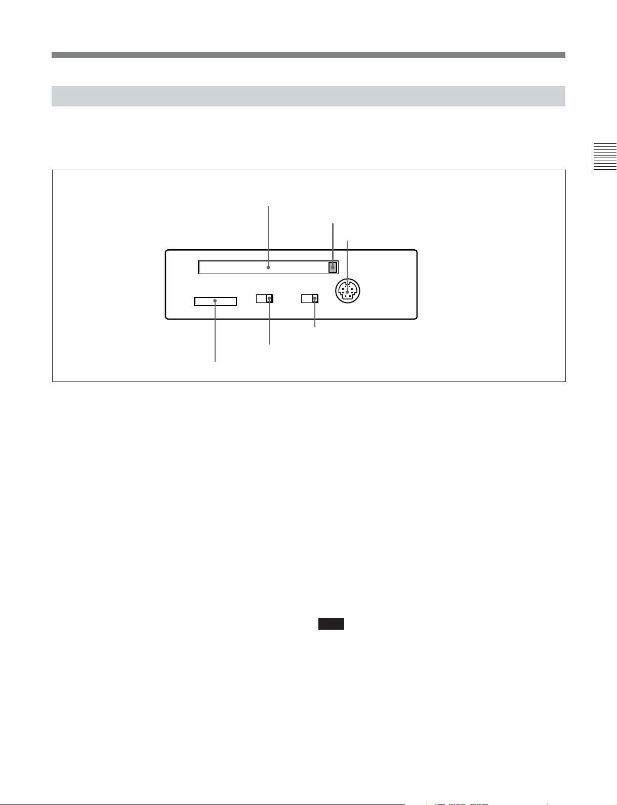
2-1-3 Switch Panel
To access the switch panel, open the lower control
panel.
1 Memory card slot
KEY INHI
OFF
ON
5 KEY INHI switch
6 “Memory Stick” slot
1 Memory card slot
Insert a memory card to update this unit’s firmware.
You can save or load setup menu settings onto the
memory card.
For details on firmware update, refer to the Maintenance
Manual Volume 1.
2 Memory card ejection button
Press to eject a memory card from the memory card
slot.
3 CONTROL PANEL connector (10-pin, round
type)
Plug in the lower control panel connection cable.
4 PANEL SELECT switch
In addition to the lower control panel, you can connect
a similar control panel to this unit. When two control
panels are connected to the unit, the PANEL SELECT
switch is used to specify which panel be enabled to
control the unit.
FRONT: Enables the control panel connected to the
CONTROL PANEL connector on the switch
panel.
On how to open the lower control panel, see the figure on
page 2-1.
Chapter 2 Location and Function of Parts
2 Memory card ejection button
3 CONTROL PANEL connector
CONTROL PANEL
PANEL SEL
FRONTREAR
4 PANEL SELECT switch
REAR: Enables the control panel connected to the
CONTROL PANEL connector on the connector
panel. When setup menu item 117 is set to PARA,
this switch position also enables the control panel
connected to the CONTROL PANEL connector
on the switch panel.
5 KEY INHI switch
Moving this switch to the ON position disables the
controls on the upper and lower control panels.
You can specify which buttons and knobs are disabled
in setup menu item 118.
6 “Memory Stick” slot
Use this to update the firmware. You can also save or
load setup menu settings onto the “Memory Stick”.
Note
After inserting a “Memory Stick” or memory card,
allow at least five seconds to elapse before removing
it.
For details on firmware update and save or load setup menu
settings, refer to the Maintenance Manual Volume 1.
Chapter 2 Location and Function of Parts 2-13

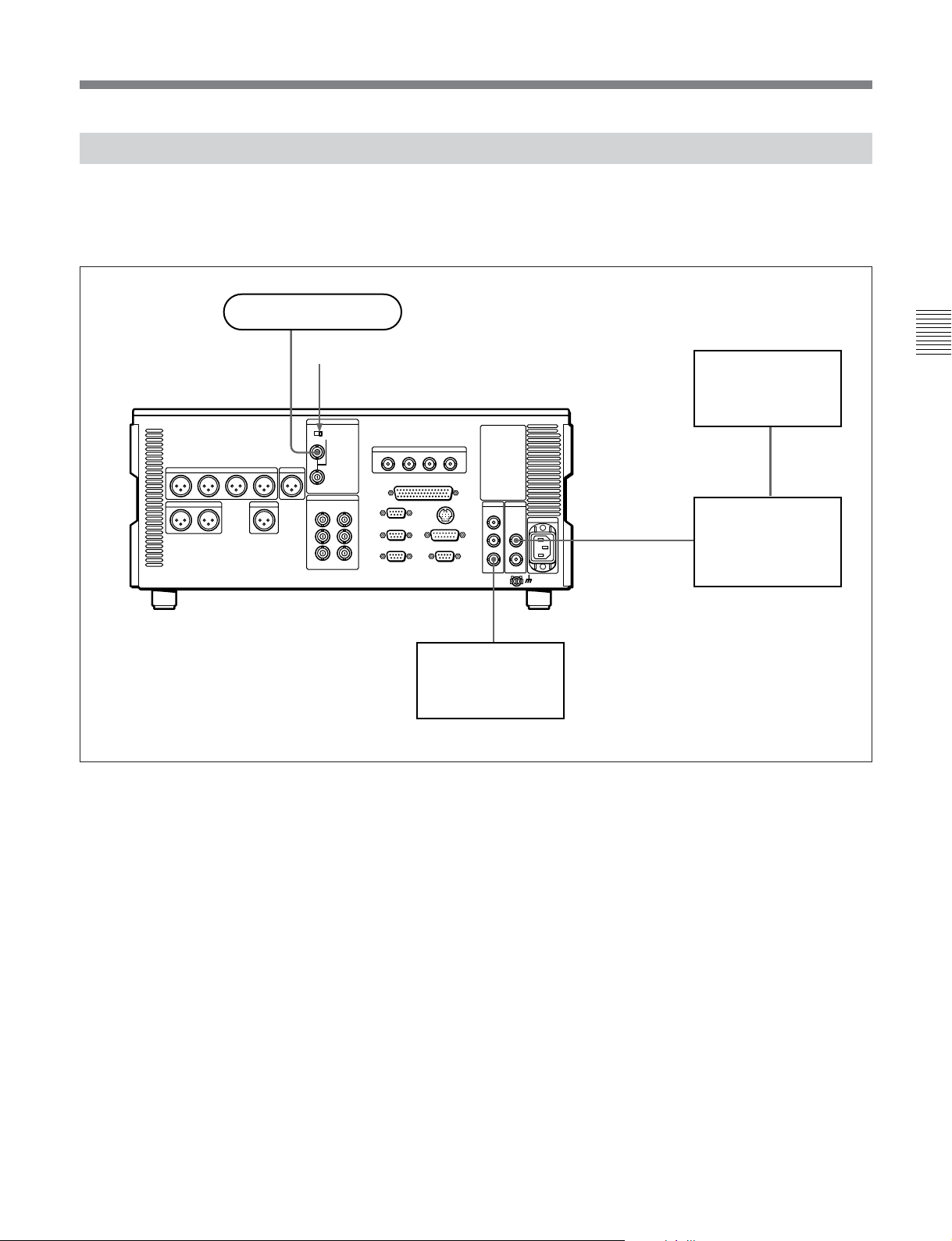
2-2 Connector Panel
Cooling fan
Chapter 2 Location and Function of Parts
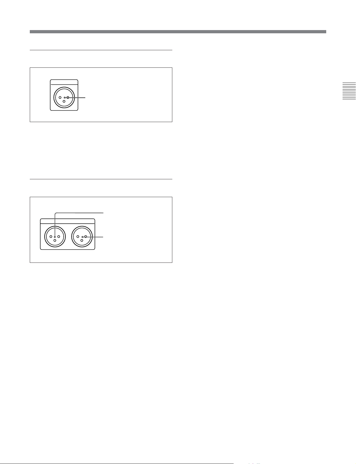
1 Analog audio output section
2 Analog video input/output section
1 Analog audio output
section
75Ω
8 Time code output section
(see page 2-17)
9 Audio monitor signal output section
(see page 2-17)
3 Digital audio output section
(see page 2-15)
4 Network connection section
(see page 2-15)
(MSW-M2100E/M2100EP only)
5 Digital signal output section
(see page 2-15)
Cooling fan
6 Power supply section
(see page 2-16)
7 External device connectors
(see page 2-16)
2 Analog video input/output section
CH1
1 AUDIO OUTPUT CH1 to CH4 connectors
AUDIO OUTPUT CUE
OUTCH2 CH3 CH4
2 CUE OUT connector
1 AUDIO OUTPUT CH1 to CH4 (channels 1 to 4)
connectors (XLR 3-pin, male)
These connectors output analog audio signals for
channels 1 to 4.
2 CUE OUT(cue audio output) connector (XLR 3pin, male)
When playing back a digital Betacam tape, this
connector outputs the cue audio signal.
REF INPUT
REF.VIDEO
OFF ON
VIDEO OUTPUT
COMPOSITE COMPONENT
1
2
3
(SUPER)
Y
R-Y
B-Y
1 REF.VIDEO INPUT
connectors and 75 Ω
termination switch
2 COMPONENT VIDEO
OUTPUT connectors
3 COMPOSITE VIDEO
OUTPUT connectors
2-14 Chapter 2 Location and Function of Parts
1 REF. (reference) VIDEO INPUT connectors
(BNC type) and 75 Ω termination switch
Input a reference video signal. Input a video signal
with chroma burst (VBS) or a monochrome video
signal (VS). When using the loop-through connection
set the switch to the OFF position, and otherwise to the
ON position.
2 COMPONENT VIDEO OUTPUT connectors
(BNC type)
These connectors output analog component video
signals (Y/R–Y/B–Y).
3 COMPOSITE VIDEO OUTPUT connectors
(BNC type)
These connectors output analog composite video
signals.
When the setting of F4 (CHARA) in function menu
page 4 is ON, connector 3 (SUPER) outputs a signal
with superimposed time code, menu settings, alarm
messages, and other text information.
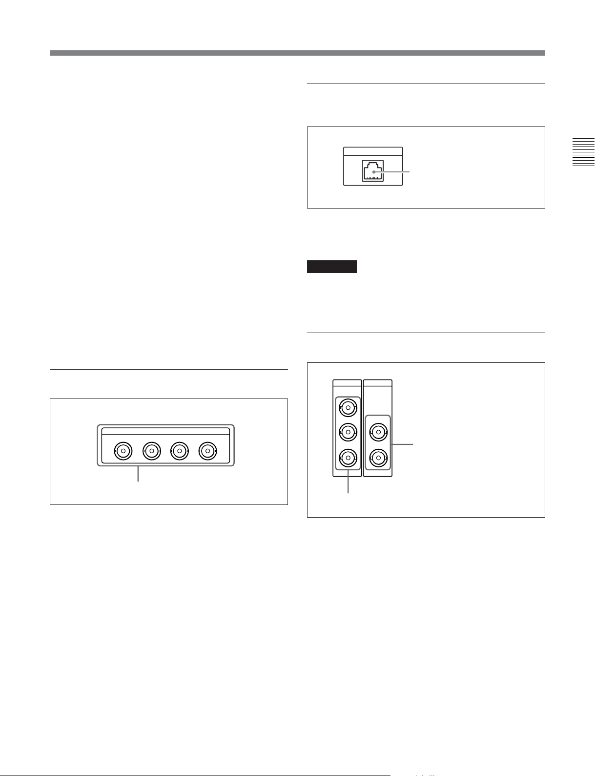
4 Network connection section (MSWM2100E/M2100EP only)
Ethernet
Ethernet connector
Ethenet connector
Connect to a network by 10/100/1000Base-T.
CAUTION
For safety, do not connect the connector for peripheral
device wiring that might have excessive voltage to this
port. Follow the instructions for this port.
5 Digital signal output section
Chapter 2 Location and Function of Parts
3 Digital audio output section
AUDIO OUTPUT(AES/EBU)
CH1/2 CH3/4 CH5/6 CH7/8
AUDIO OUTPUT (AES/EBU) connectors
AUDIO OUTPUT (AES/EBU) connectors (BNC
type)
These connectors output up to four sets (8 channels:
channels 1/2, 3/4, 5/6 and 7/8) of AES/EBU format
digital audio signals.
SDI
SDTI-CP
OUTPUT
1
2
3(
OUTPUT
1
SUPER
)
2
2 SDI OUTPUT connectors
1 SDTI-CP OUTPUT connectors
1 SDTI-CP (Serial Data Transport Interface)
OUTPUT connectors (BNC type)
Output SDTI-CP format video and audio signals.
2 SDI (Serial Digital Interface) OUTPUT
connectors (BNC type)
These connectors output D1 format digital video/audio
signals.
When the setting of F4 (CHARA) in function menu
page 4 is ON, connector 3 (SUPER) outputs a signal
with superimposed time code, menu settings, alarm
messages, and other text information.
Chapter 2 Location and Function of Parts 2-15
2-2 Connector Panel
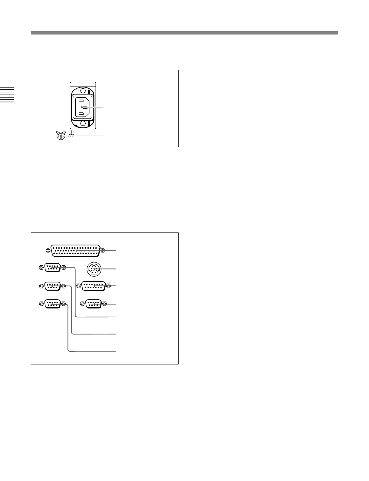
6 Power supply section
Chapter 2 Location and Function of Parts
1 AC IN connector
Use the optional power cord to connect this to an AC
outlet.
2 Ground terminal
Connect this to ground.
7 External device connectors
REMOTE 2 PARALLEL I/O(50P)
REMOTE 1-IN(9P)
REMOTE 1-OUT(9P)
RS232C
1 AC IN connector
2 Ground terminal
CONTROL PANEL
VIDEO CONTROL
(OPTION)
1 REMOTE 2 PARALLEL
I/O(50P) connector
2 CONTROL PANEL
connector
3 VIDEO CONTROL
connector
4 OPTION connector
5 REMOTE 1-IN(9P)
connector
6 REMOTE 1-OUT(9P)
connector
7 RS-232C connector
2 CONTROL PANEL connector (round type, 10-
pin)
In addition to the lower control panel, a similar control
panel can be connected to this unit. To connect such a
second control panel, use this connector. When two
control panels are connected, use the PANEL SELECT
switch on the switch panel (see page 2-13) to specify
which control panel will control this unit.
3 VIDEO CONTROL connector (D-sub 15-pin)
For remote control of the internal digital video
processor, connect an optional BVR-50/50P Remote
Control Unit.
Always power off this unit before connecting the
remote control unit.
4 OPTION connector (D-sub 9-pin)
Not used.
5 REMOTE 1-IN(9P) connector (D-sub 9-pin)
When using this unit together with an MSW-2000series VTR (recorder) or a D-1, D-2, or Betacam VTR,
and a BVE-series BVE-900/910/2000/9000/9000P/
9100/9100P or other editor, connect the optional 9-pin
remote control cable from the other unit to this
connector.
Depending on the setting of setup menu item 211, you
can use this connector alone, or in a loop-through
configuration with the REMOTE 1-OUT(9P)
connector.
6 REMOTE 1-OUT(9P) connector (D-sub 9-pin)
This provides the loop-through output for remote
control signals from the REMOTE 1-IN(9P)
connector.
Depending on the setting of setup menu item 211, you
can use this connector alone, or in a loop-through
configuration with the REMOTE 1-IN(9P) connector.
1 REMOTE 2 PARALLEL I/O(50P) connector
(D-sub 50-pin)
Connect remote control signals from an external
device.
For details, refer to the Installation Manual.
2-16 Chapter 2 Location and Function of Parts
7 RS-232C connector (D-sub 9-pin)
Use this for monitoring and diagnosis of the state of
this unit from an external computer, using ISR
(Interactive Status Reporting).
8 Time code output section
TIME CODE
OUT
TIME CODE OUT connector
TIME CODE OUT connector (XLR 3-pin, male)
This outputs the playback time code.
By setting setup menu item 606, you can also output
the time code from the internal time code generator
locked to the playback time code.
9 Audio monitor signal output section
1 MONITOR OUTPUT R
MONITOR OUTPUT
RL
connector
2 MONITOR OUTPUT L
connector
Chapter 2 Location and Function of Parts
1 MONITOR OUTPUT R connector (XLR 3-pin,
male)
This outputs the audio signals whose output
destination was set to ‘R’ with the audio signal
selection buttons in the audio control section. If
multiple tracks have been set to ‘R’, the signals of
those tracks are mixed for output.
2 MONITOR OUTPUT L connector (XLR 3-pin,
male)
This outputs the audio signals whose output
destination was set to ‘L’ with the audio signal
selection buttons in the audio control section. If
multiple tracks have been set to ‘L’, the signals of
those tracks are mixed for output.
Chapter 2 Location and Function of Parts 2-17
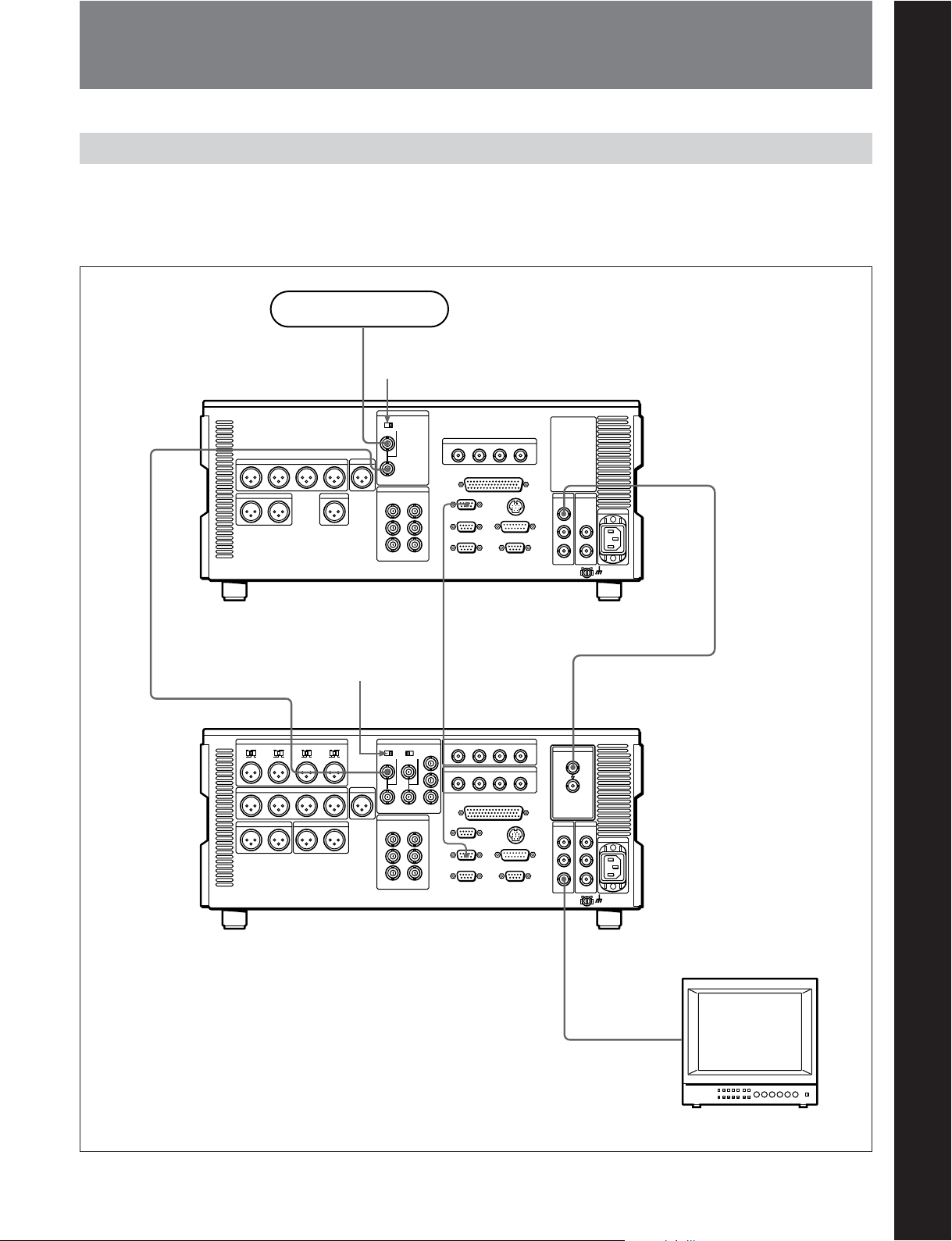
3-1 Connections to External Devices
3-1-1 Connections to Digital Devices
The following example shows the connections with an
MSW-A2000/A2000P/M2000/M2000P unit as a
recorder, with this unit used as a player.
Reference signal
Chapter 3 Preparations
REF. VIDEO INPUT
MSW-M2100/M2100P/M2100E/
M2100EP
REF. VIDEO INPUT
a)
(player)
75Ω termination
switch: ON
75 Ω termination
switch: OFF
REMOTE-IN(9P)
REMOTE 1-OUT(9P)
Chapter 3 Preparations
SDI OUTPUT
SDI INPUT
MSW-A2000/A2000P/M2000/M2000P
(recorder)
a) The figure shows the MSW-M2100/M2100P.
SDI OUTPUT 3
(SUPER)
BVM-1454 series video
monitor
Chapter 3 Preparations 3-1
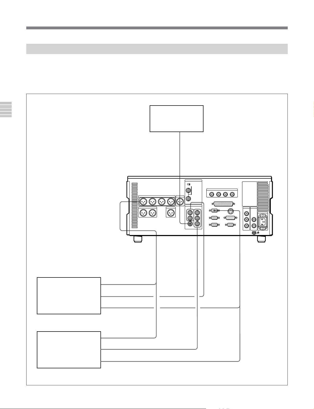
3-1 Connections to External Devices
3-1-2 Connections to Analog Devices
The following example shows the connections with an
analog VTR (a Betacam SP VTR, D2 VTR, 1-inch
VTR, etc.) for recording analog audio and video
signals played back on this unit.
Chapter 3 Preparations
MSW-M2100/M2100P/
M2100E/M2100EP
a)
COMPOSITE
VIDEO OUTPUT
AUDIO OUTPUT
CH1 to CH4
Video monitor
COMPONENT
VIDEO OUTPUT
COMPOSITE
VIDEO OUTPUT
REMOTE 1-IN
(9P)
DVR-28/28P/20/20P D2
VTR, BVH-3000/3000PS
1-inch VTR, etc. (recorder)
BVW-75/70/65/60 series
Betacam SP VTR (recorder)
3-2 Chapter 3 Preparations
AUDIO INPUT
CH1 to CH4
VIDEO INPUT
COMPOSITE
REMOTE (9P)
AUDIO INPUT
CH1 to CH4
VIDEO INPUT
COMPONENT
REMOTE (9P)
a) The figure shows the MSW-M2100/M2100P.
3-1-3 Connections Using the SDTI-CP Interface
The following example shows the connections with
devices that support the SDTI-CP interface for
dubbing video and audio signals.
Reference signal
75Ω termination switch: ON
REF. VIDEO INPUT
MSW-M2100/M2100P /M2100E/M2100EP
SDI OUTPUT 3
a)
VIdeo monitor
VIdeo monitor
SDTI-CP
OUTPUT
SDTI-CP
INPUT
Data storage unit for
nonlinear editing system
(MAV-555, etc.)
a) The figure shows the MSW-M2100/M2100P.
Chapter 3 Preparations
Chapter 3 Preparations 3-3
 Loading...