

Page 1

DIGITAL VIDEOCASSETTE PLAYER
MSW-M2100
MSW-M2100P
OPERATION MANUAL
1st Edition (Revised 2)
[English]
Page 2

WARNING
To prevent fire or shock hazard, do not
expose the unit to rain or moisture.
To avoid electrical shock, do not open
the cabinet. Refer servicing to qualified
personnel only.
This apparatus must be earthed.
WARNING: THIS WARNING IS APPLICABLE FOR
OTHER COUNTRIES.
1. Use the approved Power Cord (3-core mains lead)/
Appliance Connector/Plug with earthing-contacts that
conforms to the safety regulations of each country if
applicable.
2. Use the Power Cord (3-core mains lead)/Appliance
Connector/Plug conforming to the proper ratings
(Voltage, Ampere).
If you have questions on the use of the above Power Cord/
Appliance Connector/Plug, please consult qualified service
personnel.
For the customers in the USA
This equipment has been tested and found to comply with
the limits for a Class A digital device, pursuant to Part 15 of
the FCC Rules. These limits are designed to provide
reasonable protection against harmful interference when
the equipment is operated in a commercial environment.
This equipment generates, uses, and can radiate radio
frequency energy and, if not installed and used in
accordance with the instruction manual, may cause harmful
interference to radio communications. Operation of this
equipment in a residential area is likely to cause harmful
interference in which case the user will be required to
correct the interference at his own expense.
You are cautioned that any changes or modifications not
expressly approved in this manual could void your authority
to operate this equipment.
The shielded interface cable recommended in this manual
must be used with this equipment in order to comply with
the limits for a digital device pursuant to Subpart B of Part
15 of FCC Rules.
This symbol is intended to alert the user to
the presence of important operating and
maintenance (servicing) instructions in the
literature accompanying the appliance.
For the customers in Europe
This product with the CE marking complies with both the
EMC Directive (89/336/EEC) and the Low Voltage Directive
(73/23/EEC) issued by the Commission of the European
Community.
Compliance with these directives implies conformity to the
following European standards:
• EN60950: Product Safety
• EN55103-1: Electromagnetic Interference (Emission)
• EN55103-2: Electromagnetic Susceptibility (Immunity)
This product is intended for use in the following
Electromagnetic Environment (s):
E1 (Residential), E2 (Commercial and light industrial), E3
(Urban outdoors) and E4 (Controlled EMC environment
ex. TV studio)
WARNING: THIS WARNING IS APPLICABLE FOR USA
ONLY.
If used in USA, use the UL LISTED power
cord specified below.
DO NOT USE ANY OTHER POWER CORD.
Plug Cap Parallel blade with ground pin
(NEMA 5-15P Configuration)
Cord Type SJT, three 16 or 18 AWG
wires
Length Less than 2.5 m (8 ft 3 in)
Rating Minimum 10 A, 125 V
Using this unit at a voltage other than 120V
may require the use of a different line cord or
attachment plug, or both. To reduce the risk
of fire or electric shock, refer servicing to
qualified service personnel.
Page 3

Table of Contents
Chapter 1
Overview
Chapter 2
Location and Function of
Parts
Chapter 3
Preparations
Chapter 4
Playback
1-1 Features ........................................................................................... 1-1
1-2 Example System Configuration .................................................... 1-4
2-1 Control Panels ................................................................................ 2-1
2-1-1 Upper Control Panel .............................................................. 2-2
2-1-2 Lower Control Panel .............................................................. 2-3
2-1-3 Switch Panel ........................................................................ 2-12
2-2 Connector Panel ........................................................................... 2-13
3-1 Connections to External Devices ................................................... 3-1
3-1-1 Connections to Digital Devices ............................................. 3-1
3-1-2 Connections to Analog Devices............................................. 3-2
3-1-3 Connections Using the SDTI-CP Interface............................ 3-3
3-2 Connecting a Reference Video Signal .......................................... 3-4
3-3 Setup ................................................................................................ 3-5
3-4 Superimposed Character Information ......................................... 3-6
3-5 Cassettes .......................................................................................... 3-8
3-5-1 Cassette Types ....................................................................... 3-8
3-5-2 Inserting and Ejecting Cassettes ............................................ 3-8
3-5-3 Preventing Accidental Erasure of Recordings ....................... 3-9
4-1 Preparations for Playback ............................................................. 4-1
4-1-1 Switch and Menu Settings ..................................................... 4-1
4-1-2 Time Data Selection .............................................................. 4-2
4-1-3 Playback With SDTI-CP Output ........................................... 4-2
4-2 Playback Procedures ...................................................................... 4-3
4-2-1 Normal Playback ................................................................... 4-3
4-2-2 Playback in Jog Mode ............................................................ 4-3
4-2-3 Playback in Shuttle Mode ...................................................... 4-4
4-2-4 Playback in Variable Speed Mode......................................... 4-4
4-2-5 Playback Using the Capstan Override Function .................... 4-5
4-3 Dynamic Motion Control (DMC) Playback ................................. 4-7
4-3-1 Overview ............................................................................... 4-7
4-3-2 Storing a Varying Playback Speed in Memory ..................... 4-7
4-3-3 Executing DMC Playback ..................................................... 4-8
Chapter 5
Shot Mark Function
5-1 Overview ......................................................................................... 5-1
5-2 Shot Mark Operation Menu .......................................................... 5-2
5-3 Shot Mark Operations ................................................................... 5-3
5-3-1 Reading Shot Marks .............................................................. 5-3
5-3-2 Writing Post Marks ................................................................ 5-3
5-3-3 Shot Mark List Operations .................................................... 5-4
5-3-4 Cuing Up to Shot Marks ........................................................ 5-6
5-3-5 Reading In Shot Data ............................................................. 5-7
5-3-6 Sorting Shot Marks ................................................................ 5-8
Table of Contents 1
Page 4

Table of Contents
Chapter 6
Tele-File
Chapter 7
Function Menu
Chapter 8
Setup Menus
Chapter 9
Maintenance and
Inspection
6-1 Overview of Tele-File Functions .................................................... 6-1
6-2 Opening the Tele-File Menu ........................................................... 6-2
6-3 Tele-File Menu ................................................................................. 6-3
6-3-1 Clip Data Display .................................................................. 6-3
6-3-2 Preroll and Cue Up Using Clip Data ..................................... 6-6
6-3-3 Modifying Clip Data .............................................................. 6-7
6-3-4 Undo/Resume Functions ...................................................... 6-10
6-3-5 Displaying and Modifying Attribute Data ........................... 6-11
7-1 Overview ......................................................................................... 7-1
7-1-1 Function Menu Configuration ............................................... 7-1
7-1-2 Using the Function Menu ...................................................... 7-1
7-2 Function Menu Item List ............................................................... 7-3
8-1 Setup Menu Configuration ............................................................ 8-1
8-2 Setup Menu Operations ................................................................. 8-2
8-3 Items in the Basic Setup Menu ...................................................... 8-5
8-4 Items in the Extended Setup Menu............................................... 8-7
9-1 Removing a Cassette When Tape Slack Occurs .......................... 9-1
9-2 Head Cleaning ................................................................................ 9-1
9-3 Error Messages ............................................................................... 9-2
9-4 Moisture Condensation .................................................................. 9-4
9-5 Regular Checks ............................................................................... 9-5
9-5-1 Digital Hours Meter ............................................................... 9-5
9-5-2 Maintenance Timings ............................................................ 9-6
Appendix
Specifications......................................................................................... A-1
Index ....................................................................................................... I-1
2 Table of Contents
Page 5
1-1 Features
Chapter 1 Overview
The MSW-M2100/M2100P is a digital videocassette
player based on the MPEG IMX format.
This unit uses large scale integrated circuits for signal
processing, and has a simple internal construction,
allowing it to provide functionality at least equivalent
to a conventional VTR in a compact (4U size),
lightweight, and low power consumption design.
It not only offers playback in MPEG IMX format, but
can also play back tapes recorded in Betacam SX
format, analog Betacam format, or digital Betacam
format.
MPEG IMX format
The MPEG IMX format uses the same 12.65-mm
width tape as the conventional Betacam series. This
economical format uses 50 Mbps high image quality
MPEG-2 compression, and offers up to three hours of
recording.
The video signal compression, as in the Betacam SX
format, uses MPEG-2, and compressed data can be
passed directly without loss of quality, not only to
VTRs, but also to other devices with MPEG support,
such as nonlinear editors or servers. There is thus high
compatibility with the next generation of digital
television formats supporting MPEG-2.
The audio tracks allow up to eight channels to be
recorded, and this also provides future extensibility for
multichannel, multilingual broadcasting, data
broadcasting, and so on.
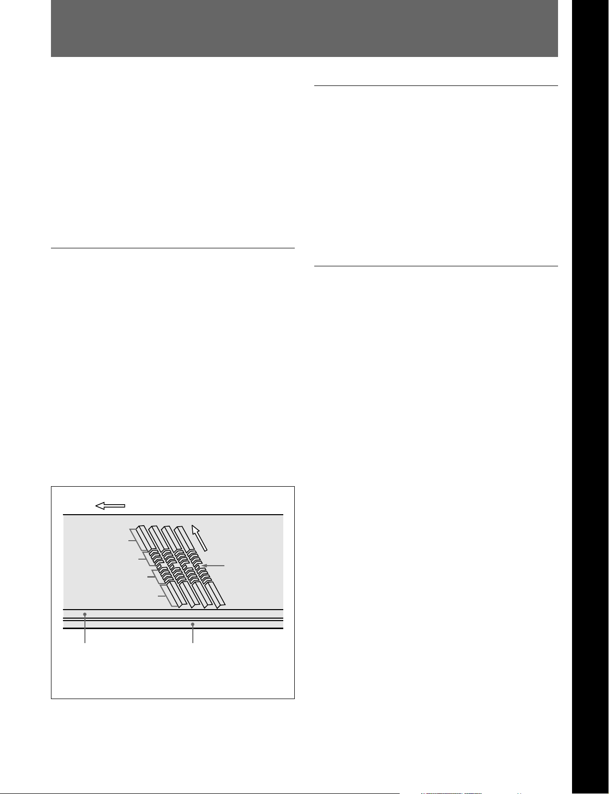
Direction of tape travel
Direction of head
Video
Audio
Audio
Video
motion
SAT
a)
High-performance heads and compatibility
playback function
Chapter 1 Overview
The newly developed high-performance heads and
dynamic tracking (DT) technology provide highdensity playback in narrow tracks with high reliability.
In addition to the MPEG IMX playback heads, this
unit is also equipped with Betacam SX format
playback heads, and analog Betacam DT heads, to
provide compatibility playback functions, and
allowing a wide variety of recorded resources to be
used effectively.
High-precision digital signal processing
and range of interfaces
The MPEG IMX VTR digital video signal processing
uses 4:2:2 component video signals complying with
ITU-R Rec 601/SMPTE 259M, which are compressed
with ISO/IEC 13818-2000 MPEG-2 compression.
While supporting a wide range of signals for output,
all of the VTR internal processing is digital, providing
high stability and reliability.
The audio signals, similarly, are based on AES/EBU
format, and are subjected to digital signal processing
while still uncompressed.
The following interfaces are standard equipment, for
ease of connection to different external devices.
• Analog composite signal input/output
• Analog component signal output
• Analog audio signal output (4 channels)
• Serial Digital Interface SMPTE 259M output
(component digital video/audio, 8 channels)
• AES/EBU serial digital audio output (8 channels)
• SDTI-CP SMPTE 326M output (MPEG video/audio
data)
• Time code output
Control (CTL) track
a) Supplemental Automatic Tracking signal
Time code track
Chapter 1 Overview 1-1
Page 6

1-1 Features
Chapter 1 Overview
High image quality MPEG-2 intraframe
encoding at 50 Mbps.
The video signal compression uses MPEG-2
intraframe encoding conforming to 4:2:2 Profile @
Main Level, with a 1:3.3 compression ratio; the data is
then recorded with a bit rate of 50 Mbps. With the
highly efficient MPEG-2 compression, the image
quality is high enough to withstand a range of editing
and dubbing operations.
The recorded MPEG-2 data can be passed directly to
other nonlinear systems, allowing optimum editing
with no loss of image quality.
High quality eight-channel audio
High quality 16 bit/48 kHz digital audio is supported.
There are eight digital audio output channels, and four
analog audio output channels.
To support even higher quality playback, there is a
four-channel mode using 24 bit/48 kHz encoding.
Thus this unit is eminently suitable not only for
multichannel applications, but also for high quality
audio editing.
Playback of SDTI compressed data
Basic operation buttons and jog/shuttle
dial
The basic buttons and jog/shuttle dial for VTR and
editing operations are provided in the conventional
VTR layout, ensuring continuity with conventional
operating panels.
Time data display
This can be selected to display a CTL counter value,
time code value, or time code user bits. It can also
display edit points and edit durations.
Menu-based control interface
The time data/menu display shows not only various
values and settings, but also the pages of a menu
system for commonly used functions. You can use the
function keys and MULTI CONTROL knob to easily
change settings.
Other operation settings, including interfacing with
external devices, can be set from the control panel by
the same type of setup menu system as on a
conventional VTR.
This unit is fitted with SDTI-CP output complying
with SMPTE 326M, and can therefore be used for
transferring MPEG-2 data, audio data, metadata, and
so on to a VTR or nonlinear device.
Newly developed multifunction control
panel
While a compact 4U size, this unit has a front panel
which provides a wide range of functions while
maintaining existing operability.
Eight-channel audio level meters
The unit has independent audio level meters and
playback level controls for all eight channels. The
level meters are on the control panel, so that when the
panel is used remotely from the main unit it is still
easy to check or adjust the audio levels.
1-2 Chapter 1 Overview
Page 7

High quality variable speed playback and
digital jog sound function
In digital BETACAM or MPEG IMX format playback,
the dedicated playback DT heads allow smooth,
noiseless playback from –1 to +3 times normal speed.
In analog Betacam compatible playback also, similar
dedicated DT heads allow noiseless playback from –1
to +3 times normal speed, and in Betacam SX format
compatible playback, special multi-head playback
technology allows noiseless playback from –1 to +2
times normal speed.
In slow motion operation, the digital jog sound
function provides the same ease of operation as a
conventional analog VTR.
Wide range of editing functions
Using this unit in combination with a recorder, you can
carry out both assemble editing and insert editing
automatically. All of the necessary editing functions
are provided to set and amend edit points, to preview
and review results of editing, and so on.
Rack mounting
Using the optional RMM-131 Rack Mount Adaptor,
you can mount the unit in a standard EIA 19-inch rack.
For details of rack mounting, refer to the Installation
Manual.
Chapter 1 Overview
DMC playback
This allows automatic playback with a varying speed
memorized beforehand for the desired segment.
Tele-File functions
Tele-File enables data writing/reading between
cassettes with memory labels and VTRs. It increases
the efficiency of operations such as cuing up and
playback, and source data management.
Remote control function
This unit can be controlled from an external remote
controller or editor through an interface complying
with RS-422A (serial 9-pin). Since two remote control
connectors are provided, you can also control a
number of VTRs simultaneously.
Additionally, a parallel (50-pin) interface is also fitted
as standard, supporting easy external control through
the parallel interface.
Chapter 1 Overview 1-3
Page 8
Chapter 1 Overview
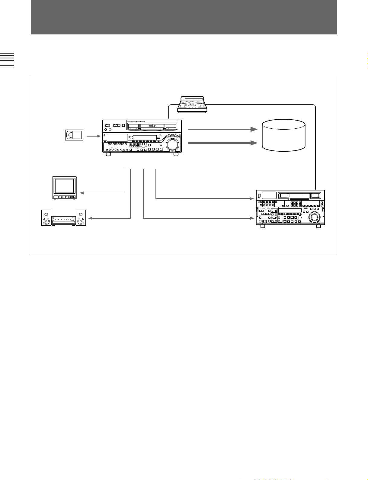
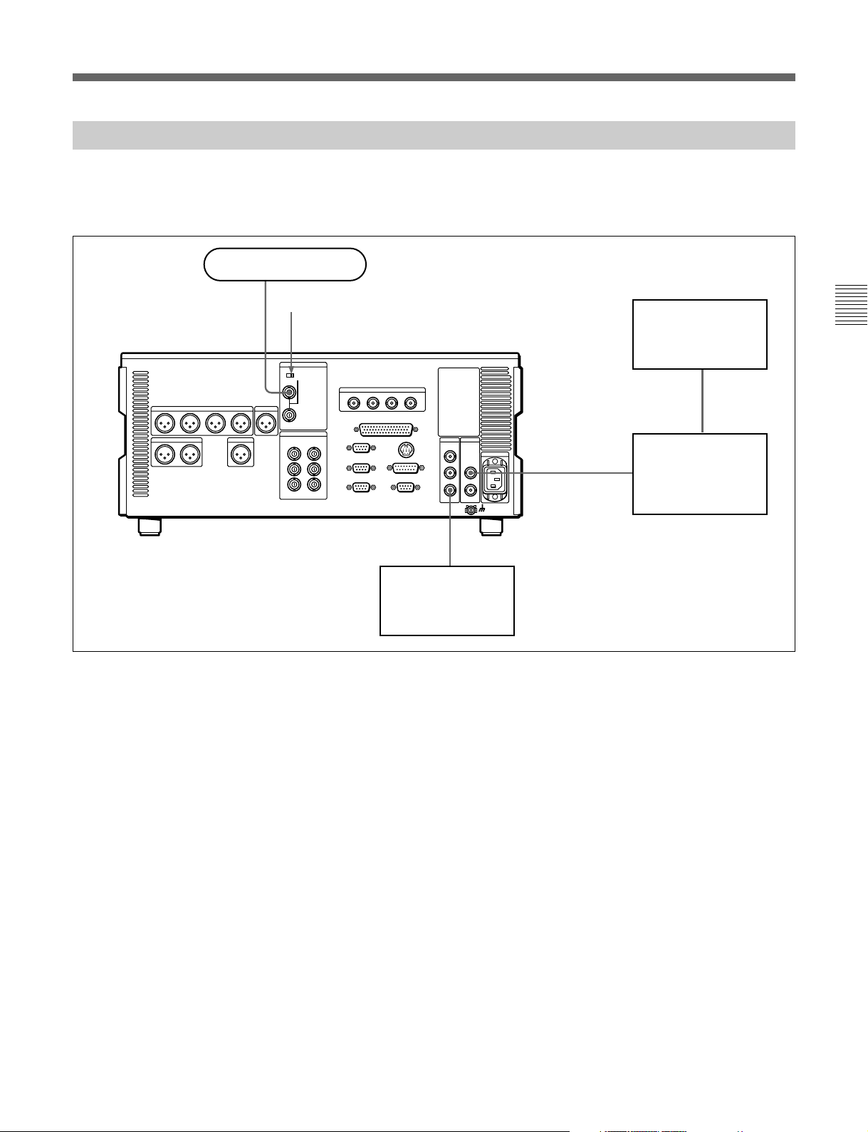
1-2 Example System Configuration
1-1 Features
The following conceptual diagram shows an example
of use.
BVE-series editor
Tape control
Digital/analog cassette
Video monitor
Analog composite
Audio monitor
MSW-M2100/M2100P
Analog audio
SDTI-CP
SDI
Analog composite/component
SDI
Audio/video
server
system
VTR with SDTI/SDI
connectors or analog VTR
1-4 Chapter 1 Overview
Page 9
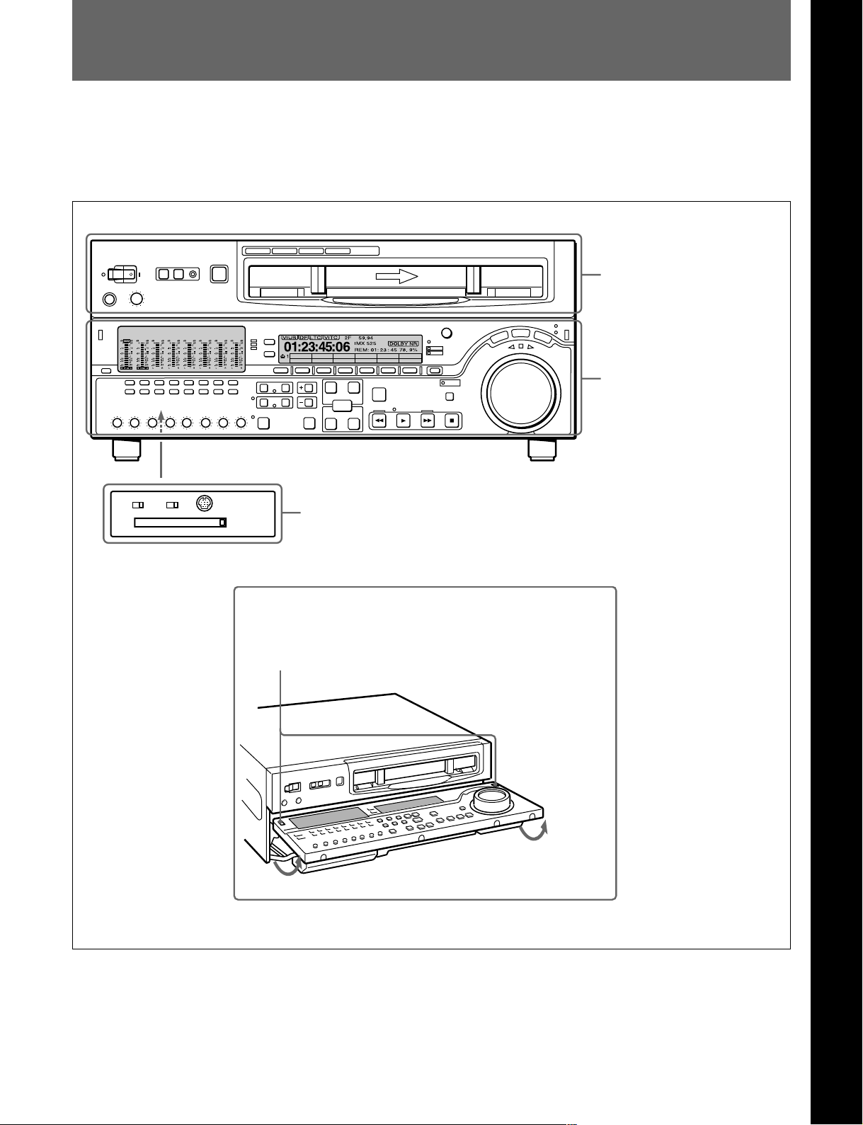
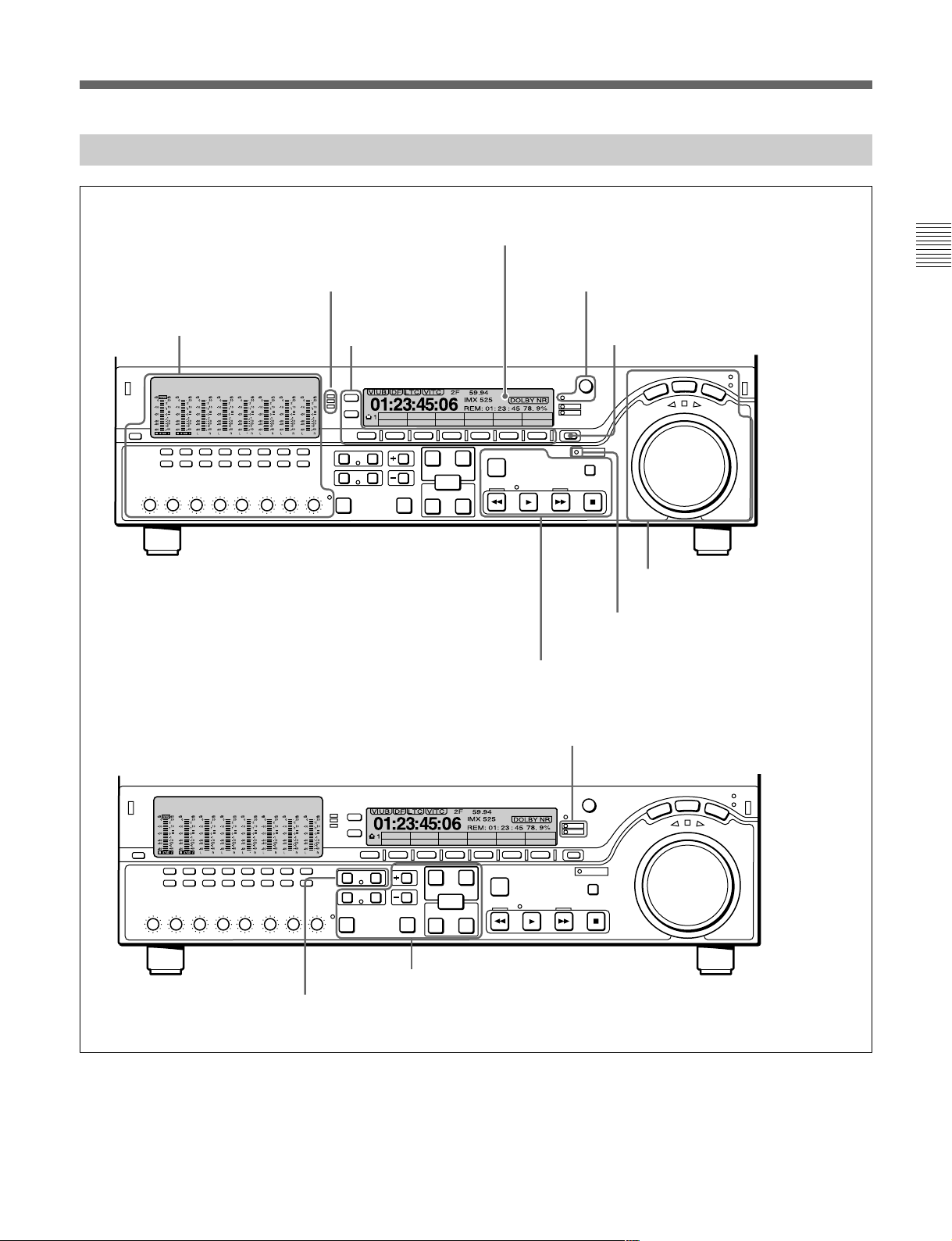
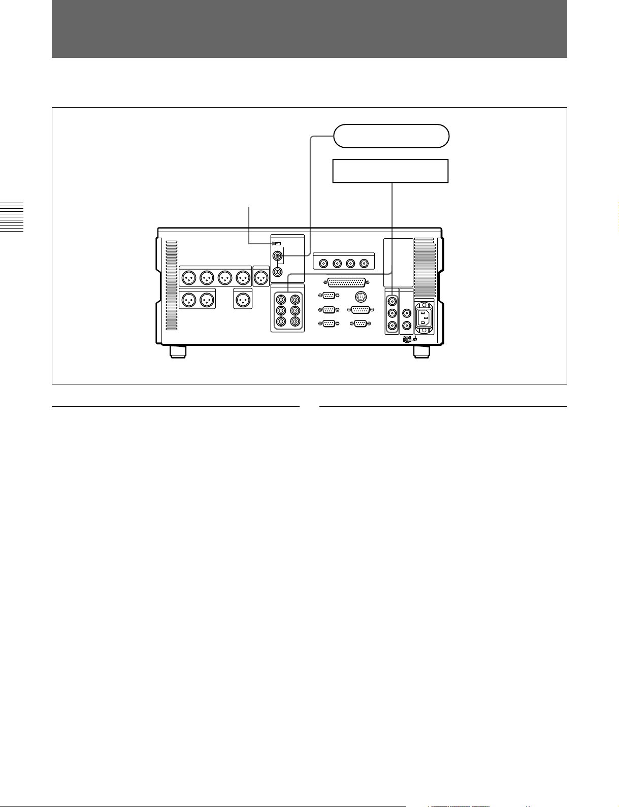
2-1 Control Panels
There are three control panels, as follows:
• Upper control panel
• Lower control panel
• Switch panel
Z
CTL/TC
TC
MENU
Upper control panel
Lower control panel
Chapter 2 Location and Function of Parts
Chapter 2 Location and Function of Parts
(see page 2-2)
(see page 2-3)
KEY INHIBIT
PANEL SELECT CONTROL PANEL
OFF
ON
FRONTREAR
Switch panel (access by opening the lower control panel)
Lower control panel unlock buttons
Pushing in these buttons allows you to open the lower control panel.
(see page 2-12)
Chapter 2 Location and Function of Parts 2-1
Page 10
2-1 Control Panels
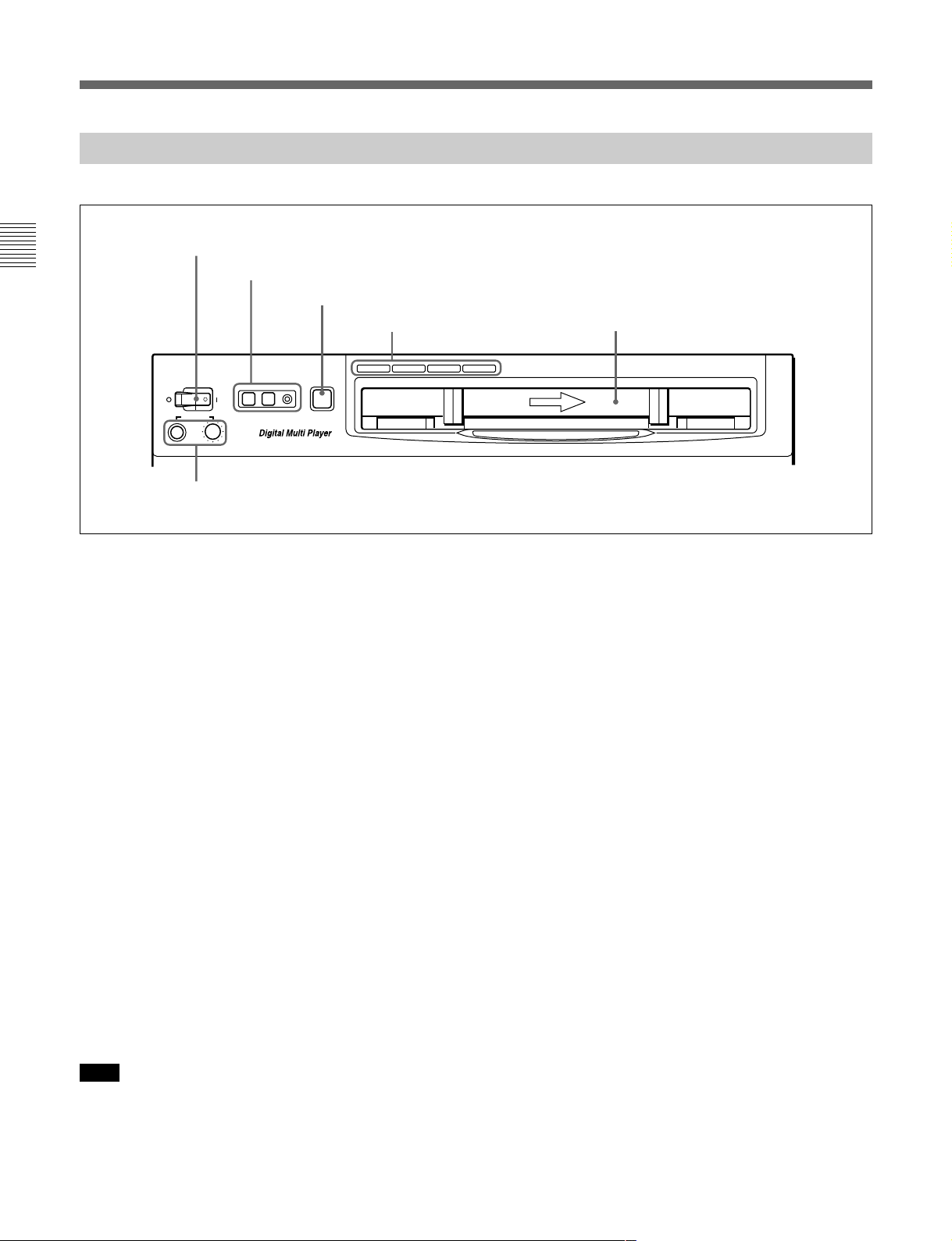
2-1-1 Upper Control Panel
Chapter 2 Location and Function of Parts
1 POWER switch
2 REMOTE buttons and RS-232C indicator
3 EJECT button
POWER
PHONES
5 PHONES jack and control
REMOTE
1(9P) 2(50P) RS-232C
EJECT
Z
4 Format indicators
BETACAM/SP
BETACAM SX MPEG IMX
Cassette compartment
Digital BETACAM
1 POWER switch
Pressing the ‘ ) ’ side of the switch powers the unit on.
When the unit is powered on, the audio setting display
section (see page 2-4) and the time data/menu display
section (see page 2-6) light.
2 REMOTE buttons and RS-232C indicator
Press one of these buttons to select the device
controlling this unit.
1(9P): This unit is controlled by the device connected
to the REMOTE 1-IN(9P) or REMOTE 1OUT(9P) connector. The button lights.
2(50P): This unit is controlled by the device
connected to the REMOTE 2 PARALLEL I/
O(50P) connector. The button lights.
RS-232C indicator: This indicator lights when this
unit is controlled through the RS-232C connector.
3 EJECT button
To eject the cassette, press this button. While the
cassette is being ejected, this button lights.
When using the lower control panel as remote control
panel, press the DELETE button and STOP button at
the same time to eject the cassette.
4 Format indicators
The BETACAM/SP, BETACAM SX, MPEG IMX, or
Digital BETACAM indicator lights depending on the
current playback format.
The BETACAM/SP indicator lights when the format is
Betacam or Betacam SP.
5 PHONES jack and control
Connect stereo headphones with an impedance of
8 ohms to monitor the sound during playback.
The control knob adjusts the volume.
It is possible to set an internal board switch so that the
output volume from the MONITOR OUTPUT L and R
connectors is controlled simultaneously.
For details, refer to the Installation Manual.
Note
Ejecting with the EJECT button is a local operation. It
is not possible to eject a cassette in another unit by
remote control.
2-2 Chapter 2 Location and Function of Parts
Page 11
2-1-2 Lower Control Panel
1 Audio control section
(see page 2-4)
2 CHANNEL CONDITION
indicator
(see page 2-5)
3 Menu control buttons
(see page 2-5)
4 Time data/menu display section
5 MULTI CONTROL knob and SHIFT
indicator
6 RESET button
MENU
CTL/TC
TC
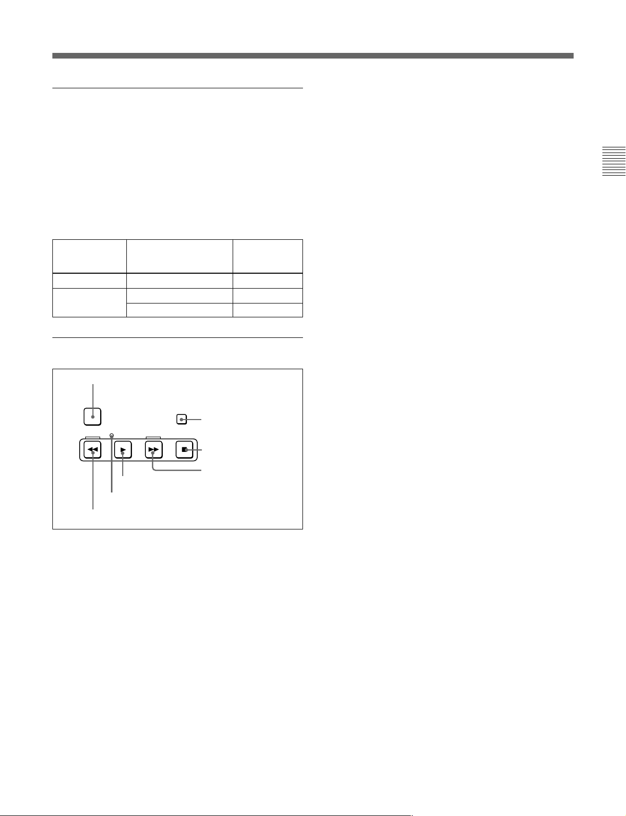
8 GOOD SHOT REC INHI indicator
9 Tape transport control section
(see page 2-6)
(see page 2-7)
(see page 2-7)
7 Search control section
(see page 2-9)
(see page 2-9)
Chapter 2 Location and Function of Parts
(see page 2-7)
qa DMC playback control section
qs Shot mark section
CTL/TC
TC
(see page 2-11)
MENU
q; ALARM indicator and KEY INHI
indicator
(see page 2-10)
(see page 2-10)
Chapter 2 Location and Function of Parts 2-3
Page 12
2-1 Control Panels
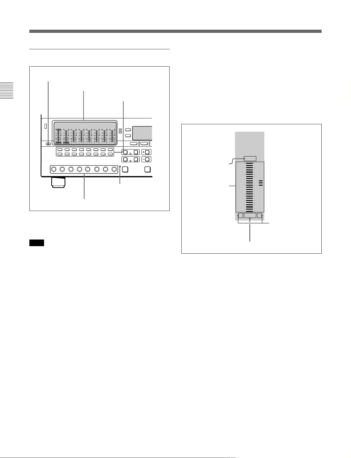
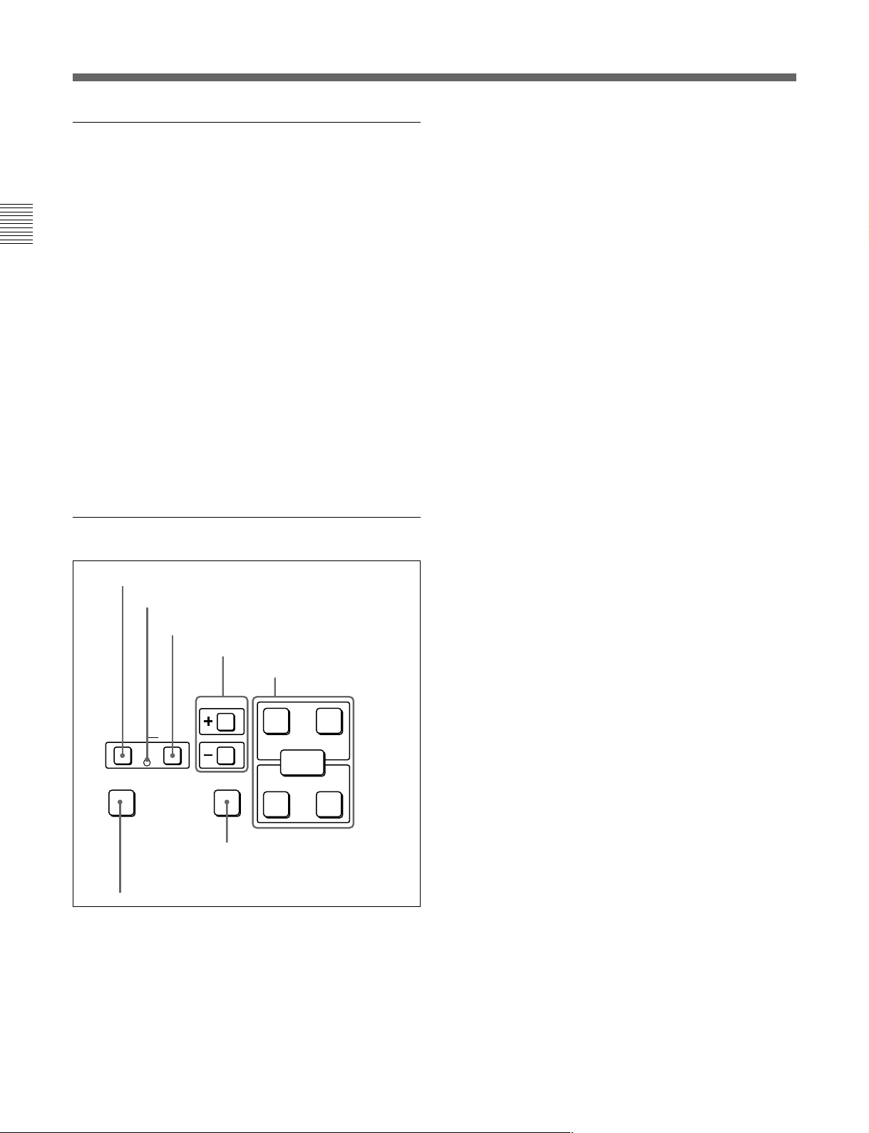
1 Audio control section
1 DISPLAY FULL/FINE button
Chapter 2 Location and Function of Parts
In the audio control section, you can select and display
output signals for audio channels 1 to 8.
2 Audio setting display section
3 Audio signal
selection buttons
5 ALL CH
indicator
4 PB controls
FINE: The display is enlarged, with a step of
0.25 dB. A segment indicating the reference level
lights. In this mode only the segment of the
display corresponding to the current audio level
lights. If the audio level exceeds the maximum
display level, the top segment flashes, and if the
audio level goes below the minimum display
level, the bottom segment flashes.
2 Audio setting display section
OVER
OVER indicator
Level meter
dB dB
-10
-20
-30
-40
-60
L R
0
EMPH
20
2
10
1
0
-1
-10
-20
-2
-40
Monitor channel L
and R indicators
Note
When a tape recorded in MPEG IMX 24-bit/4-channel
mode is played back, the audio setting display section
displays only audio signal settings for channels 1 to 4.
Audio signal settings for channels 5 to 8 are not
displayed.
When a digital Betacam tape is played back, the digital
audio levels are displayed on the level meters for
channels 1 to 4 in the audio setting display section 2.
The level meter for channel 7 displays the cue audio
level always in FULL mode (see the description of the
DISPLAY FULL/FINE button 1).
1 DISPLAY FULL/FINE button
Pressing this button toggles the display mode of the
level meters in the audio setting display section
between FULL and FINE.
FULL: The display covers the range –60 dB to 0 dB
or –40 dB to +20 dB as selected using setup menu
item 806. In this mode the segment of the display
corresponding to the current audio level and all
lower segments light.
EMPH indicator
OVER indicator: While the unit is in playback
mode, this lights when the level of the audio
signal on the corresponding channel exceeds the
maximum level that can be indicated on the level
meter.
Level meter: Displays the audio signal level when
the unit is in playback mode. You can use the
setup menu to switch the display mode between
PEAK.0 (0 dB is maximum level) and REF.0 (0
dB is the reference level). You can also use the
DISPLAY FULL/FINE button 1 to enlarge the
display only near the reference level.
When a digital Betacam tape is played back, the
level meter for channel 7 displays the cue audio
level.
Monitor channel L and R indicators: Indicate
whether or not the signals of the track are output
to the MONITOR OUTPUT L and R connectors
or the PHONES jack. ‘L’ lights to indicate output
to the left monitor channel, and ‘R’ lights to
indicate output to the right monitor channel.
2-4 Chapter 2 Location and Function of Parts
Page 13

EMPH (emphasis) indicator: During playback, this
lights when the emphasis setting is on for the
audio signal on the corresponding track.
3 Audio signal selection buttons (CH1 to CH8)
The buttons in the upper and lower rows select tracks
to be output to the MONITOR OUTPUT L and R
connectors on the connector panel or the PHONES
jack on the upper control panel. The buttons in the
upper row (L row) select tracks for output to the
MONITOR OUTPUT L connector, and the buttons on
the lower row (R row) select tracks for output to the
MONITOR OUTPUT R connector. You can obtain the
mixed output of multiple tracks by simultaneously
pressing multiple buttons in the upper or lower rows.
For example, simultaneously press the CH1, CH2, and
CH3 buttons in the upper row to mix the signals of
audio tracks 1, 2, and 3 for output to the MONITOR
OUTPUT L connector.
4 PB (playback) controls
These adjust individually the playback levels on
channels 1 to 8.
During playback, press to protrude the control knobs
and adjust the level while monitoring the audio level
indication on the level meters in the audio setting
display section.
When the control knobs are pushed in, the playback
levels return to the preset levels, and cannot be
adjusted.
When playing back a digital Betacam tape, you can
use the control knob for channel 7 to adjust the cue
audio playback level.
About the CH8/ALL CH (channels) control
You can choose to use the rightmost CH8/ALL CH
control to adjust the playback level of all channels.
This setting is made in setup menu item 132. When
adjustment by the CH8/ALL CH control is enabled,
the CH1 to CH7 controls are disabled.
5 ALL CH (channels) indicator
This indicator lights when adjustment of all audio
channels by the rightmost PB control (CH8/ALL CH)
is selected.
2 CHANNEL CONDITION indicator
A three-color indicator shows the state of the playback
signal.
Green: The state of the playback signal is good.
Yellow: The playback signal is somewhat
deteriorated, but playback is possible.
Red: The playback signal is deteriorated.
When this indicator remains on, head cleaning or
an internal inspection is necessary.
Note
During analog playback, indications are by green and
red only.
3 Menu control buttons
These buttons are used for function menu (see the
following section “Overview of the function menu”)
and setup menu (see Chapter 8) operations. The page
buttons (V, v, and HOME) select menu pages, and the
function buttons (F1 to F6) make function settings.
V: Selects the next page in the order HOME t 1 t
2 t 3 t 4 t 5 t HOME.
v: Selects the next page in the order HOME t 5 t
4 t 3 t 2 t 1 t HOME.
When there are setup menu definitions on page 6,
page 6 is displayed between page 5 and the HOME
page.
HOME: Selects the function menu HOME page.
When at least one user-defined function key is set
in the HOME2 page, pressing the HOME button
toggles the menu page display between HOME
and HOME2.
F1 to F6: Make settings for the items displayed in the
upper line of the menu display (the menu item
display line). Pressing one of these buttons
changes the setting for the corresponding item and
displays the setting in the lower line of the menu
display.
If there is no setting displayed in the lower line of
the menu display, even though a menu item is
displayed in the upper line, pressing the
corresponding function button moves to a lower
menu level.
Chapter 2 Location and Function of Parts
Overview of the function menu
The function menu provides convenient access to
frequently used function settings, such as video signal
output level and time code settings.
For details on the function menu, see Chapter 7.
Chapter 2 Location and Function of Parts 2-5
Page 14
2-1 Control Panels
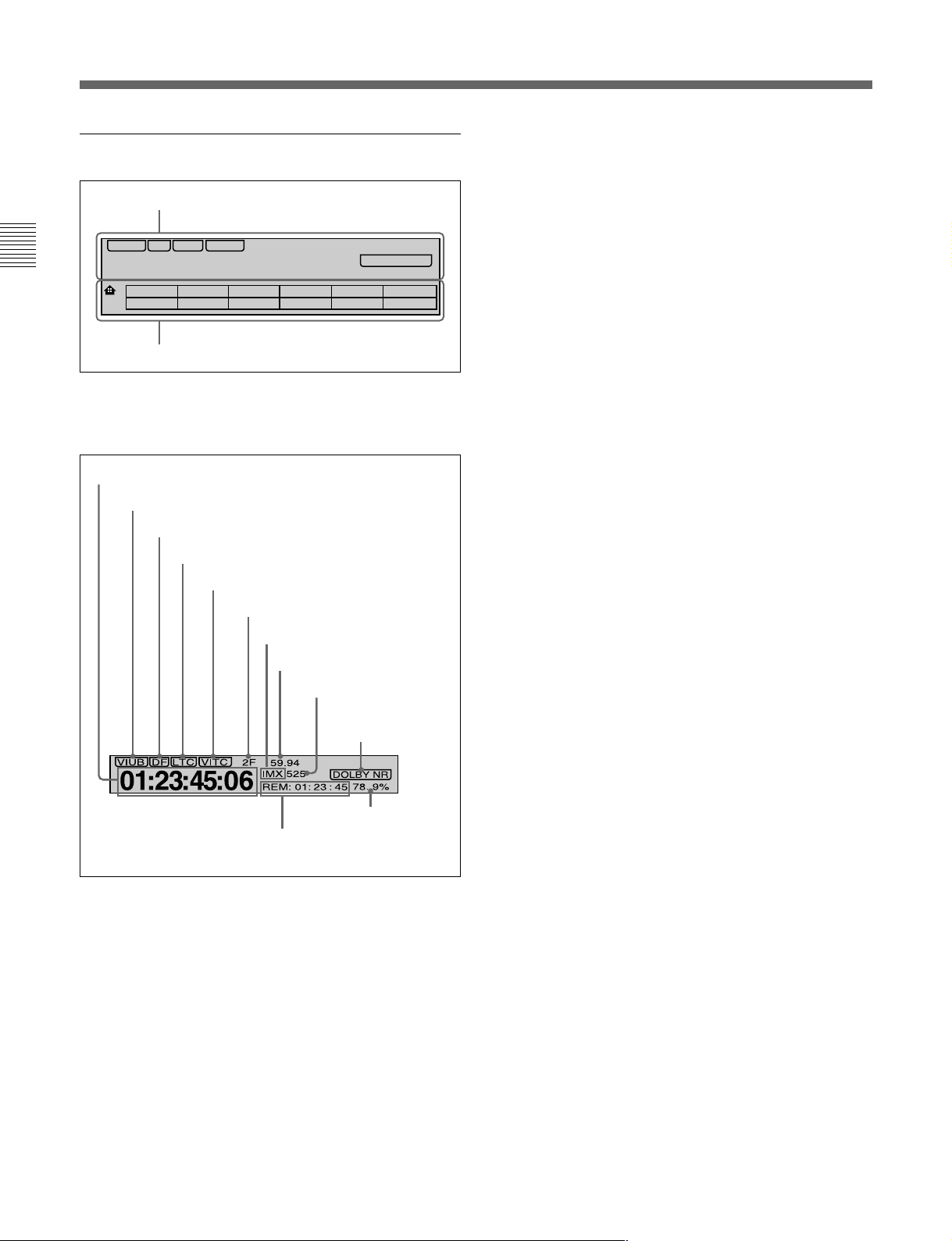
4 Time data/menu display section
1 Time data display
VIUB VITC
DF LTC
Chapter 2 Location and Function of Parts
01: : :23 45 06
1
2 Menu display
1 Time data display
This displays indicators relating to time data and other
indicators.
Time data display area 1
Time data type indicator
DF indicator
LTC indicator
VITC indicator
2F 59.94
IMX 525
REM: 01: 23 : 45 78. 9%
CTL/TCTCMENU
Capstan lock mode indicator
Playback format indicator
System frequency indicator
525/625 indicator
DOLBY NR
DF (drop-frame) indicator (525-line mode only)
This lights when values of drop-frame mode time code
are displayed.
LTC indicator
Regardless of the display in time data display
area 1, this indicator lights when LTC values are being
read.
VITC indicator
Regardless of the display in time data display
area 1, this indicator lights when VITC values are
being read.
Capstan lock mode indicator
This indicates the capstan lock mode (2F, 4F, or 8F)
set in function menu page 4 or in setup menu item 106.
Playback format indicator
This indicator shows the current playback format.
DB: Digital BETACAM format
IMX: MPEG IMX format, bit rate 50 Mbps, 8 audio
channels
IMX4: MPEG IMX format, bit rate 50 Mbps, 4 audio
channels
SX: Betacam SX format
SP: Betacam SP format
No display: Betacam format
DOLBY NR indicator
Speed indication area
Time data display area 2
Time data display area 1
Normally this displays a CTL count, time code value,
or user bit value according to the setting in function
menu HOME page for F4 (CTL/TC).
Time data type indicator
This indicates the type of data displayed in the time
data display area 1.
LTC (longitudinal time code): Time code recorded
on a longitudinal track on the tape
LUB: LTC user bit values
VITC (vertical interval time code): Time code
recorded in the vertical blanking interval
VIUB: VITC user bit value
System frequency indicator
Displays the current playback field frequency, and the
bit rate of recording or SDTI-CP output.
525/625 indicator
This indicator shows the number of scan lines for the
television standard (525 (NTSC) or 625 (PAL))
selected using setup menu item 013.
Time data display area 2
Displays data types and time data such as the time
code of edit points and the total time of that tape.
The following data types are shown.
TOTL: Total time of the tape.
REM: Remaining time on the tape.
Depending on the setting of F5 (T INFO) on function
menu page 3, either TOTL (TOTAL) or REM
(REMAIN) is displayed.
The values displayed are approximate values
calculated on the basis of the detected tape diameter.
They are not precise to units of seconds.
2-6 Chapter 2 Location and Function of Parts
Page 15
IN: video IN point
OUT: video OUT point
AIN: audio IN point
AOUT: audio OUT point
DUR: duration value
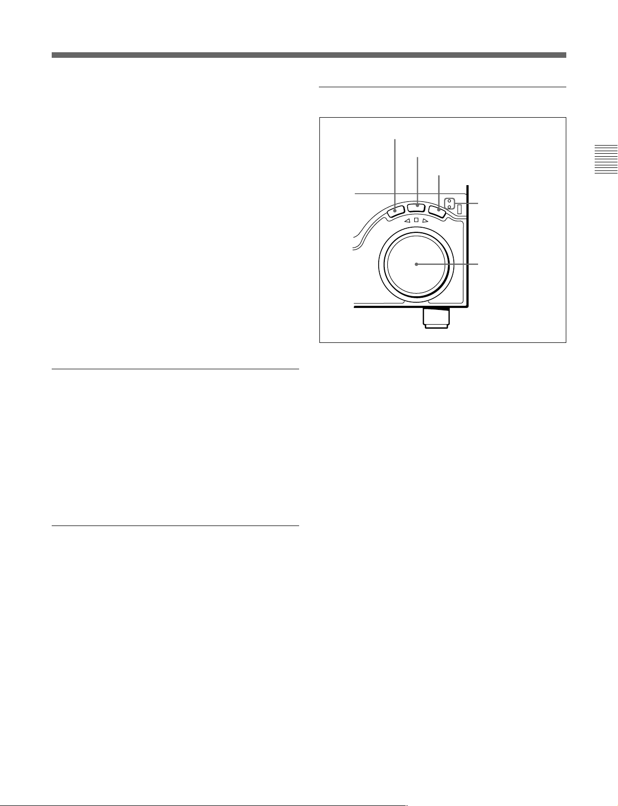
7 Search control section
1 SHUTTLE button
2 JOG button
DOLBY NR indicator
1)
This lights when the Dolby noise-reduction
circuit is
functioning.
Speed indication area
This indicates the speed of a DMC playback.
In the time data display area 2, “DMC SPD” is
displayed during a DMC playback.
2 Menu display
This displays the function menu and setup menu.
For details on the function menu, see Chapter 7 and for
details on the setup menu, see Chapter 8.
5 MULTI CONTROL knob and SHIFT
indicator
In function menu operations, rotate the MULTI
CONTROL knob to change settings that flash in the
menu display section. In setup menu operations, rotate
this knob to select menu items.
The SHIFT indicator lights when you press this knob
in. In this state, the value of the setting changes by a
greater amount when you rotate the knob.
3 VAR button
SHUTTLE/VAR
T
T
U
H
S
REVERSE
VA
R
FORWARD
JOG
JOG
E
L
4 SHUTTLE/VAR
and JOG
indicators
5 Search dial
1 SHUTTLE button
To use the search dial for playback in shuttle mode,
press this button, turning it on.
For details of playback in shuttle mode, see the description
of the search dial 5.
2 JOG button
To use the search dial for playback in jog mode, press
this button, turning it on.
For details of playback in jog mode, see the description of
the search dial 5.
Chapter 2 Location and Function of Parts
6 RESET button
To reset the CTL value displayed in time data display
area 1, press this button.
Resetting the CTL value erases all edit points.
3 VAR (variable) button
To use the search dial for playback in variable speed
mode, press this button, turning it on.
For details of playback in variable speed mode, see the
description of the search dial 5.
..........................................................................................................................................................................................................
1) Dolby noise reduction: Dolby noise reduction
manufactured under license from Dolby Laboratories
Licensing Corporation. “DOLBY” and the double-D
symbol ; are trademarks of Dolby Laboratories
Licensing Corporation.
Chapter 2 Location and Function of Parts 2-7
Page 16

2-1 Control Panels
4 SHUTTLE/VAR and JOG indicators
Either of the indicators is lit to show the current search
mode or the mode used last. When the unit is turned
on, the SHUTTLE/VAR indicator lights.
When the SHUTTLE/VAR indicator is lit: Shuttle
or variable speed mode
Chapter 2 Location and Function of Parts
When the JOG indicator is lit: Jog mode
5 Search dial
Turn this to carry out playback in the modes shown in
the following table. Turning the dial clockwise lights
the H indicator and plays back in the forward
direction. Turning the dial counterclockwise lights the
h indicator and plays back in the reverse direction.
When the tape is stopped or the unit is turned on, the
s indicator lights. Pressing the dial toggles between
shuttle and jog modes or between variable speed and
jog modes.
You can carry out noiseless playback in the following
speed ranges depending on the tape format.
Digital Betacam: –1 to +3 times normal speed
MPEG IMX: –1 to +3 times normal speed
Betacam SX: –1 to +2 times normal speed
Betacam/Betacam SP: –1 to +3 times normal speed
Playback modes using the search dial
Playback mode
Shuttle
Jog Press the JOG button or the search
Variable speed Press the VAR button, turning it on,
Capstan override
Operations and functions
Press the SHUTTLE button or the
search dial so that the SHUTTLE
button lights, then turn the search dial.
Playback is carried out at a speed
determined by the position of the
search dial. The playback speed
range is as follows:
• Using a Digital Betacam tape: –50 to
+50 times normal speed
• Using an MPEG IMX tape: –60 to
+60 times normal speed
• Using a Betacam SX tape: –60 to
+60 times normal speed
• Using an analog Betacam tape: –35
to +35 times normal speed for 525/
60 mode or –42 to +42 times normal
speed for 625/50 mode
The search dial has detents at the still
position and at ±5 times normal
speed.
The maximum shuttle mode playback
speed can be changed by changing
the setting of setup menu item 102
(see page 8-7)
dial so that the JOG button lights, then
turn the search dial. Playback is
carried out at a speed determined by
the speed of rotation of the search
dial. The playback speed range is –1
to +1 time normal speed.
The search dial has no detents.
then turn the search dial. You can
control the playback speed finely (a
maximum of 51 steps) in the range in
which noiseless playback is possible.
The search dial has detents at the still
position and at the normal speed
position.
For details on operation, see page
4-5.
.
2-8 Chapter 2 Location and Function of Parts
Setting setup menu item 101 (see page 8-7) to KEY enables
you to use only the SHUTTLE, JOG, and VAR buttons to
select shuttle/jog/variable speed modes.
Page 17
8 GOOD SHOT REC INHI (shot mark
recording inhibit) indicator
This indicator is on or off according to the
combination of the F5 (RECINH) setting on function
menu page 4 and the record inhibit plug on the
cassette, as shown in the following table. When this
indicator is on, writing shot marks on tape is
prohibited.
GOOD SHOT REC INHI indicator indications
RECINH setting
ON
OFF Record inhibit Lit
State of the record
inhibit plug on the
cassette
Record inhibit/permit Lit
Record permit
GOOD SHOT
REC INHI
indicator state
Off
2 STANDBY button
When a cassette is inserted and this button is off, to put
the unit in standby mode, press the button, turning it
on.
In standby mode, the drum is rotating and the tape is in
contact with the drum. As a result, playback can start
immediately.
To end standby mode, press the STANDBY button,
turning it off.
If 8 minutes (value can be varied using setup menu
item 501) elapse in standby mode, the unit
automatically switches out of standby mode to protect
the tape.
3 STOP button
To stop playback, press this button, turning it on.
When you stop playback, the unit switches to still
playback.
Chapter 2 Location and Function of Parts
9 Tape transport control section
1 PREROLL button
PREROLL
REW
PLAY
5 PLAY button
6 SERVO indicator
7 REW button
1 PREROLL button
Press this button to cue up to the preroll point (before
the IN point by the time set as the preroll time) on the
tape. You can change or select the preroll time and the
state of the unit at the end of preroll (“stop mode”
still playback mode) using setup menu item 001 or
401.
Cuing up to DMC playback control points
Hold down the STUNT IN, STUNT OUT, PLAY IN,
or PLAY OUT button while pressing this button to cue
up to the corresponding DMC playback control point.
F FWD
STANDBY
STOP
2 STANDBY button
3 STOP button
4 F FWD button
1)
or
Fault display function
The STOP button flashes when there is no external
reference signal input or the input external reference
signal is not synchronized to the input video signal.
4 F FWD (fast forward) button
To fast forward the tape, press this button, turning it
on.
5 PLAY button
To start playback, press this button, turning it on.
To operate in capstan override mode
Hold down this button, and turn the search dial.
For details of capstan override mode, see page 4-5.
6 SERVO indicator
Lights when the drum servo and capstan servo are
locked.
7 REW (rewind) button
To rewind the tape, press this button, turning it on.
..........................................................................................................................................................................................................
1) Stop mode: The state in which the device currently the
subject of operation is stopped, and the STOP button is
lit.
Chapter 2 Location and Function of Parts 2-9
Page 18
2-1 Control Panels
q; ALARM indicator and KEY INHI
indicator
ALARM indicator
This lights when a hardware error is detected on the
unit, and goes off when the error is resolved.
Chapter 2 Location and Function of Parts
When this indicator is lit, an error message appears in
the time data/menu display section. If you are using
the SDI OUTPUT 3 (SUPER) or COMPOSITE
VIDEO OUTPUT 3 (SUPER) connector, then when
the setting of F4 (CHARA) in function menu page 4 is
ON, the error message also appears on the monitor
screen.
For details on error messages, refer to Section 1-24 in the
Maintenance Manual Volume 1.
KEY INHI (inhibit) indicator
This indicator lights when the KEY INHIBIT switch
on the switch panel (see page 2-12) is set to ON.
qa DMC playback control section
1 DMC EDIT button
2 MEMORY indicator
DMC EDIT
MEMORY
LEARN
3 DELETE button
4 TRIM buttons
TRIM
DELETE
CUE/PLAY
6 CUE/PLAY button
5 DMC playback control
point setting buttons
PLAY
IN OUT
ENTRY
STUNT
IN OUT
2 MEMORY indicator
When memorizing the playback speed using the DMC
EDIT button, this indicator flashes as the playback
speed is captured to memory, and lights continuously
once the speed is captured.
3 DELETE button
This deletes an existing DMC playback control point.
Hold down this button and press the STUNT IN,
STUNT OUT, PLAY IN, or PLAY OUT button which
is lit, indicating an existing DMC playback control
point, to delete the corresponding DMC playback
control point. The button either goes off or flashes.
When the button flashes, it is necessary to set the
deleted DMC playback control point again.
To cancel the DMC mode, hold down the DMC button
and press the DELETE button.
4 TRIM buttons
Use these buttons to trim a DMC playback control
point to single-frame precision.
Hold down the STUNT IN, STUNT OUT, PLAY IN,
or PLAY OUT button, and press one of these buttons.
The ‘+’ button advances the corresponding edit point
by one frame, and the ‘–’ button sets it back by one
frame.
Pressing one of these buttons while holding down the
PLAY button adjusts the tape speed by +8% or –8%
correspondingly. (Capstan override function)
5 DMC playback control point setting buttons
STUNT IN button and STUNT OUT button
To set a speed variation start or end point, hold down
the STUNT IN button or STUNT OUT button, and
press the ENTRY button.
After you have made the setting, pressing the STUNT
IN button or STUNT OUT button displays the speed
variation start or end point set in time data display area
2.
7 LEARN button
1 DMC EDIT button
To carry out recording of playback at any speed
between –1 and +3 times normal (between –1 and +2
times normal for Betacam SX), automatic playback,
and automatic editing.
For playback in feed mode, hold down this button and
press the PLAY button.
Playback in feed mode requires a setting of extended
menu item 111.
2-10 Chapter 2 Location and Function of Parts
PLAY IN button and PLAY OUT button
To set an on-air start or end point, hold down the
PLAY IN button or PLAY OUT button, and press the
ENTRY button.
After you have made the setting, pressing the PLAY
IN button or PLAY OUT button displays the on-air
start or end point set in time data display area 2.
Page 19

ENTRY button
Use this for setting DMC playback control points and
so on.
• To set a speed variation start or end point: Hold down
the STUNT IN button or STUNT OUT button, and
press this button.
• To set an on-air start or end point: Hold down the
PLAY IN button or PLAY OUT button, and press
this button.
6 CUE/PLAY (cue up/playback) button
After setting an on-air start point (PLAY IN point) and
an on-air end point (PLAY OUT point), pressing this
button cues up the tape to the on-air start point. The
button then starts flashing to indicate that the unit is
ready for DMC playback operation. To start DMC
playback, press the button again.
7 LEARN button
After setting a speed variation start point (STUNT IN
point) and a speed variation end point (STUNT OUT
point), pressing this button makes the tape start
running. You can then use the search dial to vary the
tape speed, which is automatically stored in memory.
After thus storing the tape speed variation in memory,
pressing this button starts an automatic playback
between the speed variation start and end points at the
stored speed.
Chapter 2 Location and Function of Parts
qs Shot mark section
1 LIST button
LIST GOOD SHOT MARK
REC/
ERASE
1 LIST button
Use this button to read in and list shot marks.
2 REC/ERASE indicator
This lights in the state in which writing, amending, and
deleting of shot marks is enabled and flashes while a
shot mark is actually being written, amended or
deleted.
3 MARK button
Hold this button down for 2 seconds or more, to enable
writing, amending, and deleting of shot marks.
2 REC/ERASE indicator
3 MARK button
Chapter 2 Location and Function of Parts 2-11
Page 20
2-1 Control Panels
2-1-3 Switch Panel
To access the switch panel, open the lower control
panel.
Chapter 2 Location and Function of Parts
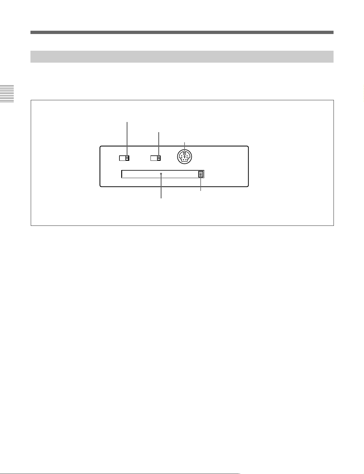
1 KEY INHIBIT switch
Moving this switch to the ON position disables the
controls on the upper and lower control panels.
You can specify which buttons and knobs are disabled
in setup menu item 118.
2 PANEL SELECT switch
In addition to the lower control panel, you can connect
a similar control panel to this unit. When two control
panels are connected to the unit, the PANEL SELECT
switch is used to specify which panel be enabled to
control the unit.
FRONT: Enables the control panel connected to the
CONTROL PANEL connector on the switch
panel.
REAR: Enables the control panel connected to the
CONTROL PANEL connector on the connector
panel. When setup menu item 117 is set to PARA,
this switch position also enables the control panel
connected to the CONTROL PANEL connector
on the switch panel.
1 KEY INHIBIT switch
KEY INHIBIT
ON
PANEL SELECT CONTROL PANEL
OFF
On how to open the lower control panel, see the figure on
page 2-1.
2 PANEL SELECT switch
3 CONTROL PANEL connector
FRONTREAR
4 Memory card ejection button
5 Memory card slot
4 Memory card ejection button
Press to eject a memory card from the memory card
slot.
5 Memory card slot
Insert a memory card to update this unit’s firmware.
You can save or load setup menu settings onto the
memory card.
For details on firmware update, refer to the Maintenance
Manual Volume 1.
3 CONTROL PANEL connector (10-pin, round
type)
Plug in the lower control panel connection cable.
2-12 Chapter 2 Location and Function of Parts
Page 21
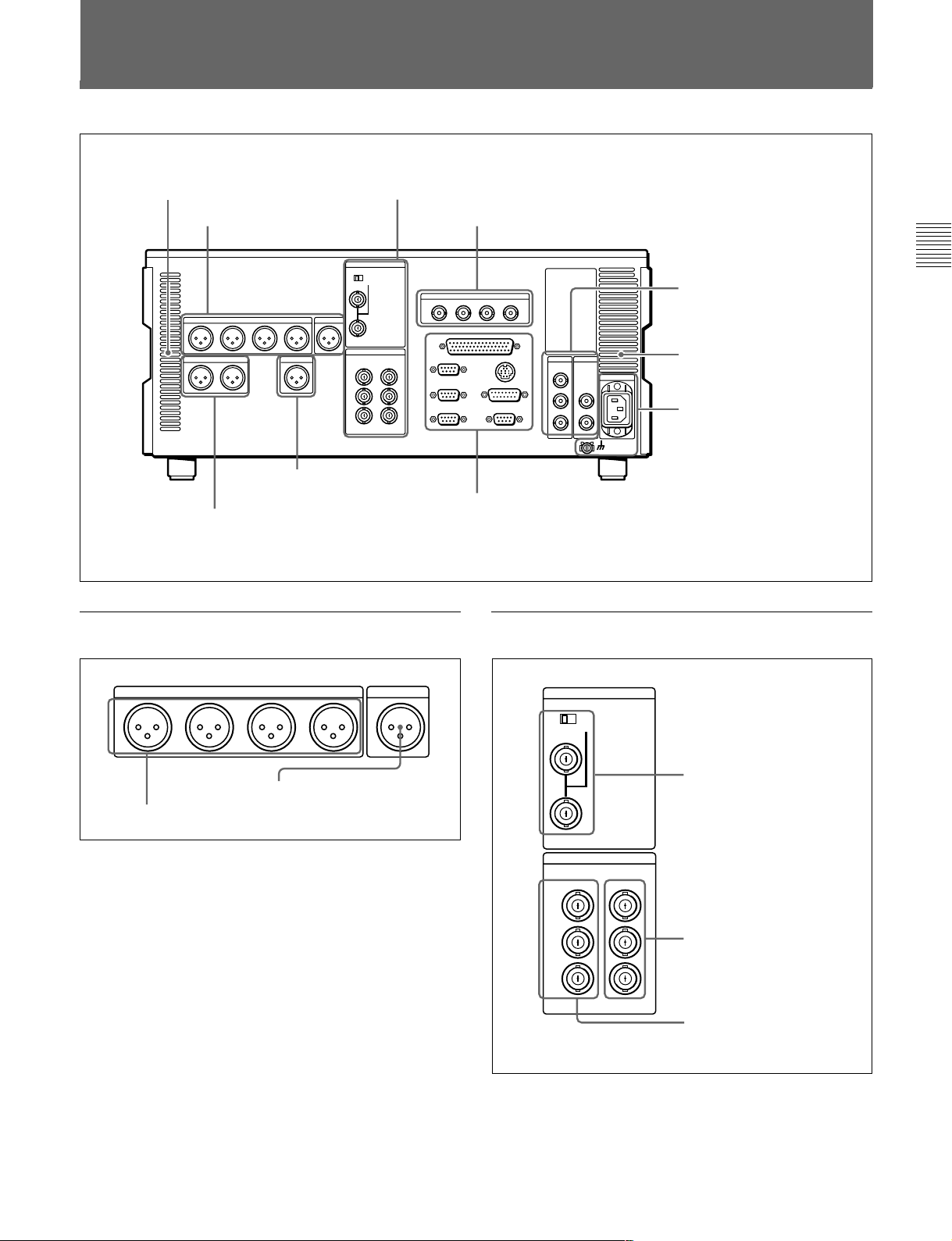
2-2 Connector Panel
Cooling fan
1 Analog audio output
section
7 Time code output section
(see page 2-15)
8 Audio monitor signal output section
page 2-16)
1 Analog audio output section
2 Analog video input/output section
3 Digital audio output section
75Ω
6 External device connectors
(see
2 Analog video input/output section
(see page 2-14)
4 Digital signal output
section
2-14)
Cooling fan
5 Power supply section
(see page 2-14)
(see page 2-15)
Chapter 2 Location and Function of Parts
(see page
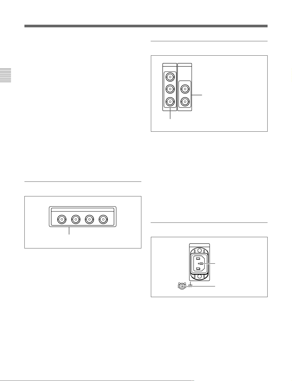
CH1
1 AUDIO OUTPUT CH1 to CH4 connectors
AUDIO OUTPUT CUE
OUTCH2 CH3 CH4
2 CUE OUT connector
1 AUDIO OUTPUT CH1 to CH4 (channels 1 to 4)
connectors (XLR 3-pin, male)
These connectors output analog audio signals for
channels 1 to 4.
2 CUE OUT(cue audio output) connector (XLR 3pin, male)
When playing back a digital Betacam tape, this
connector outputs the cue audio signal.
REF INPUT
REF.VIDEO
OFF ON
VIDEO OUTPUT
COMPOSITE COMPONENT
1
2
3
(SUPER)
Y
R-Y
B-Y
1 REF.VIDEO INPUT
connectors and 75 Ω
termination switch
2 COMPONENT VIDEO
OUTPUT connectors
3 COMPOSITE VIDEO
OUTPUT connectors
Chapter 2 Location and Function of Parts 2-13
Page 22
2-2 Connector Panel
1 REF. (reference) VIDEO INPUT connectors
(BNC type) and 75 Ω termination switch
Input a reference video signal. Input a video signal
with chroma burst (VBS) or a monochrome video
signal (VS). When using the loop-through connection
set the switch to the OFF position, and otherwise to the
ON position.
Chapter 2 Location and Function of Parts
2 COMPONENT VIDEO OUTPUT connectors
(BNC type)
These connectors output analog component video
signals (Y/R–Y/B–Y).
3 COMPOSITE VIDEO OUTPUT connectors
(BNC type)
These connectors output analog composite video
signals.
When the setting of F4 (CHARA) in function menu
page 4 is ON, connector 3 (SUPER) outputs a signal
with superimposed time code, menu settings, alarm
messages, and other text information.
3 Digital audio output section
AUDIO OUTPUT(AES/EBU)
CH1/2 CH3/4 CH5/6 CH7/8
4 Digital signal output section
SDI
SDTI-CP
OUTPUT
1
2
3(
1 SDTI-CP (Serial Data Transport Interface)
OUTPUT connectors (BNC type)
Output SDTI-CP format video and audio signals.
2 SDI (Serial Digital Interface) OUTPUT
connectors (BNC type)
These connectors output D1 format digital video/audio
signals.
When the setting of F4 (CHARA) in function menu
page 4 is ON, connector 3 (SUPER) outputs a signal
with superimposed time code, menu settings, alarm
messages, and other text information.
OUTPUT
1
SUPER
)
2
2 SDI OUTPUT connectors
1 SDTI-CP OUTPUT connectors
AUDIO OUTPUT (AES/EBU) connectors
AUDIO OUTPUT (AES/EBU) connectors (BNC
type)
These connectors output up to four sets (8 channels:
channels 1/2, 3/4, 5/6 and 7/8) of AES/EBU format
digital audio signals.
5 Power supply section
1 AC IN connector
2 Ground terminal
1 AC IN connector
Use the optional power cord to connect this to an AC
outlet.
2 Ground terminal
Connect this to ground.
2-14 Chapter 2 Location and Function of Parts
Page 23
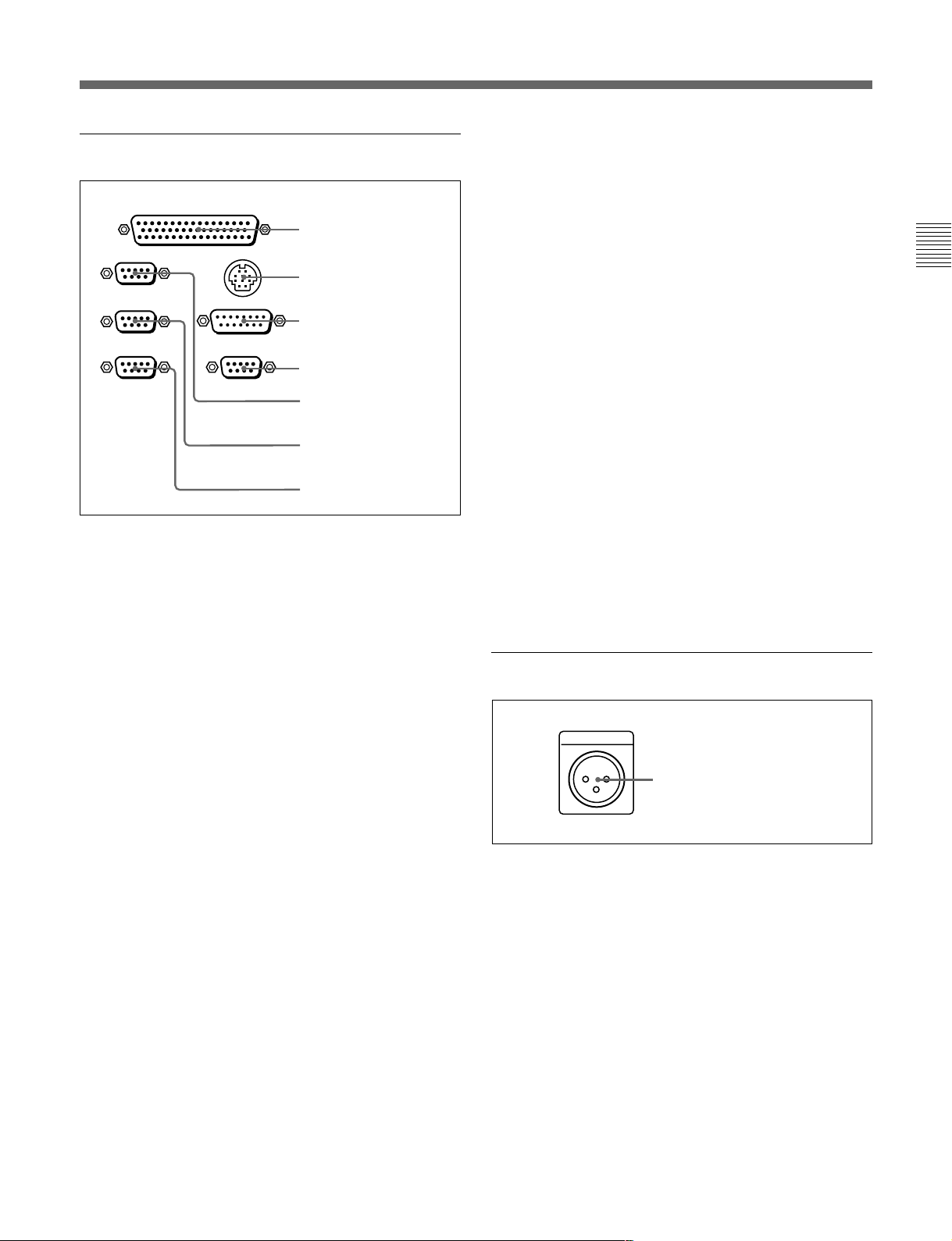
6 External device connectors
TIME CODE
OUT
REMOTE 2 PARALLEL I/O(50P)
1 REMOTE 2 PARALLEL
REMOTE 1-IN(9P)
REMOTE 1-OUT(9P)
RS232C
CONTROL PANEL
VIDEO CONTROL
(OPTION)
I/O(50P) connector
2 CONTROL PANEL
connector
3 VIDEO CONTROL
connector
4 OPTION connector
5 REMOTE 1-IN(9P)
connector
6 REMOTE 1-OUT(9P)
connector
7 RS-232C connector
5 REMOTE 1-IN(9P) connector (D-sub 9-pin)
When using this unit together with an MSW-A2000/
A2000P/M2000/M2000P (recorder) or a D-1, D-2, or
Betacam VTR, and a BVE-series BVE-900/910/2000/
9000/9000P/9100/9100P or other editor, connect the
optional 9-pin remote control cable from the other unit
to this connector.
Depending on the setting of setup menu item 211, you
can use this connector alone, or in a loop-through
configuration with the REMOTE 1-OUT(9P)
connector.
6 REMOTE 1-OUT(9P) connector (D-sub 9-pin)
This provides the loop-through output for remote
control signals from the REMOTE 1-IN(9P)
connector.
Depending on the setting of setup menu item 211, you
can use this connector alone, or in a loop-through
configuration with the REMOTE 1-IN(9P) connector.
Chapter 2 Location and Function of Parts
1 REMOTE 2 PARALLEL I/O(50P) connector
(D-sub 50-pin)
Connect remote control signals from an external
device.
For details, refer to the Installation Manual.
2 CONTROL PANEL connector (round type, 10pin)
In addition to the lower control panel, a similar control
panel can be connected to this unit. To connect such a
second control panel, use this connector. When two
control panels are connected, use the PANEL SELECT
switch on the switch panel (see page 2-12) to specify
which control panel will control this unit.
3 VIDEO CONTROL connector (D-sub 15-pin)
For remote control of the internal digital video
processor, connect an optional BVR-50/50P Remote
Control Unit.
Always power off this unit before connecting the
remote control unit.
7 RS-232C connector (D-sub 9-pin)
Use this for monitoring and diagnosis of the state of
this unit from an external computer, using ISR
(Interactive Status Reporting).
7 Time code output section
TIME CODE OUT connector
TIME CODE OUT connector (XLR 3-pin, male)
This outputs the playback time code.
By setting setup menu item 606, you can also output
the time code from the internal time code generator
locked to the playback time code.
4 OPTION connector (D-sub 9-pin)
Not used.
Chapter 2 Location and Function of Parts 2-15
Page 24

2-2 Connector Panel
8 Audio monitor signal output section
MONITOR OUTPUT
RL
Chapter 2 Location and Function of Parts
1 MONITOR OUTPUT R connector (XLR 3-pin,
male)
This outputs the audio signals whose output
destination was set to ‘R’ with the audio signal
selection buttons in the audio control section. If
multiple tracks have been set to ‘R’, the signals of
those tracks are mixed for output.
1 MONITOR OUTPUT R
connector
2 MONITOR OUTPUT L
connector
2 MONITOR OUTPUT L connector (XLR 3-pin,
male)
This outputs the audio signals whose output
destination was set to ‘L’ with the audio signal
selection buttons in the audio control section. If
multiple tracks have been set to ‘L’, the signals of
those tracks are mixed for output.
2-16 Chapter 2 Location and Function of Parts
Page 25
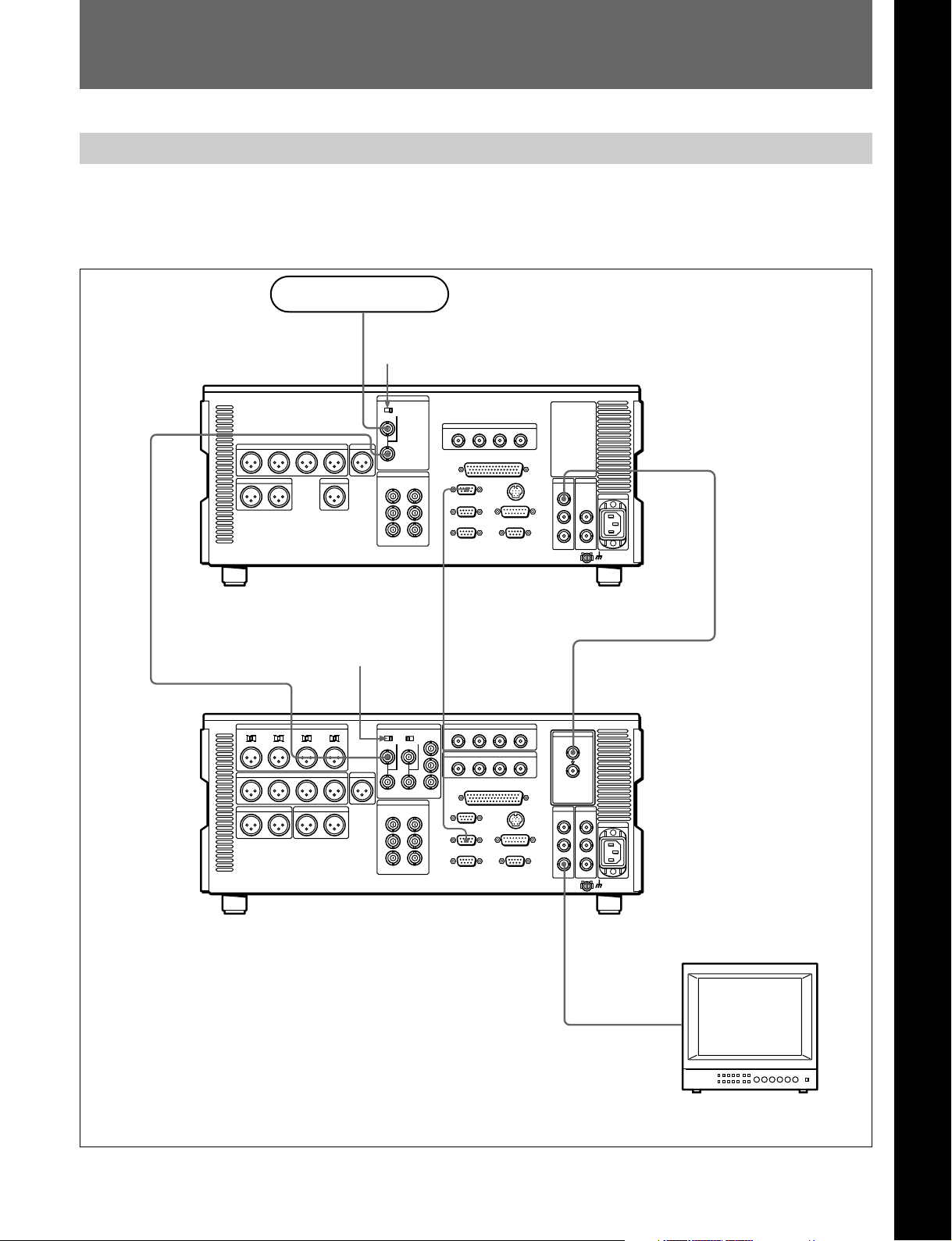
3-1 Connections to External Devices
3-1-1 Connections to Digital Devices
The following example shows the connections with an
MSW-A2000/A2000P/M2000/M2000P unit as a
recorder, with this unit used as a player.
Reference signal
75 Ω termination
switch: OFF
REF. VIDEO INPUT
Chapter 3 Preparations
Chapter 3 Preparations
SDI OUTPUT
MSW-M2100/M2100P (player)
75Ω termination
switch: ON
REF. VIDEO INPUT
MSW-A2000/A2000P/M2000/M2000P
(recorder)
REMOTE-IN(9P)
REMOTE 1-OUT(9P)
SDI OUTPUT 3
(SUPER)
SDI INPUT
BVM-1454 series video
monitor
Chapter 3 Preparations 3-1
Page 26
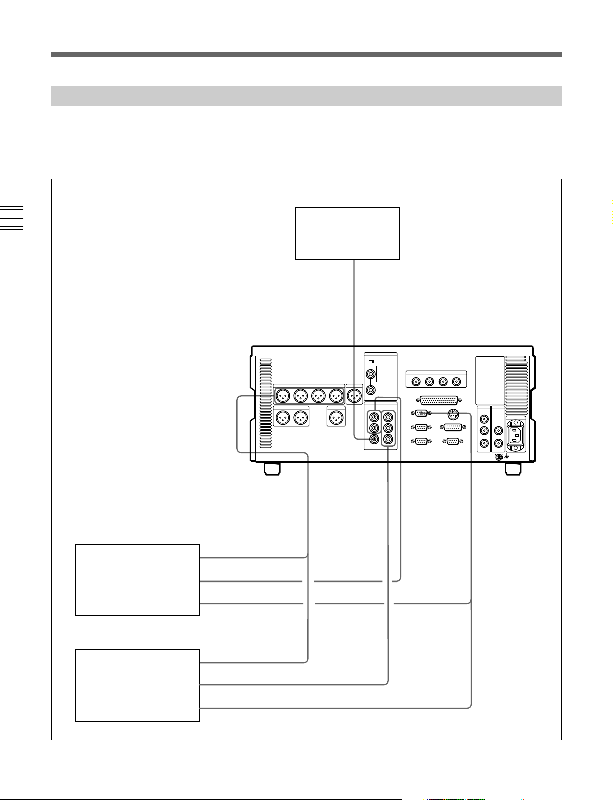
3-1 Connections to External Devices
3-1-2 Connections to Analog Devices
The following example shows the connections with an
analog VTR (a Betacam SP VTR, D2 VTR, 1-inch
VTR, etc.) for recording analog audio and video
signals played back on this unit.
Chapter 3 Preparations
MSW-M2100/M2100P
COMPOSITE
VIDEO OUTPUT
AUDIO OUTPUT
CH1 to CH4
Video monitor
COMPONENT
VIDEO OUTPUT
COMPOSITE
VIDEO OUTPUT
REMOTE 1-IN
(9P)
DVR-28/28P/20/20P D2
VTR, BVH-3000/3000PS
1-inch VTR, etc. (recorder)
BVW-75/70/65/60 series
Betacam SP VTR (recorder)
3-2 Chapter 3 Preparations
AUDIO INPUT
CH1 to CH4
VIDEO INPUT
COMPOSITE
REMOTE (9P)
AUDIO INPUT
CH1 to CH4
VIDEO INPUT
COMPONENT
REMOTE (9P)
Page 27
3-1-3 Connections Using the SDTI-CP Interface
The following example shows the connections with
devices that support the SDTI-CP interface for
dubbing video and audio signals.
Reference signal
75Ω termination switch: ON
REF. VIDEO INPUT
MSW-M2100/M2100P
SDI OUTPUT 3
VIdeo monitor
SDTI-CP
OUTPUT
SDTI-CP
INPUT
VIdeo monitor
Data storage unit for
nonlinear editing system
(MAV-555, etc.)
Chapter 3 Preparations
Chapter 3 Preparations 3-3
Page 28
3-2 Reference Signals for Video Output and Servo System
3-2 Connecting a Reference Video Signal
Connect a reference video signal as shown below.
Chapter 3 Preparations
Reference signal for video output and
servo system
75 Ω termination switch: ON
MSW-M2100/M2100P
Reference video signal
Video monitor
• SDI OUTPUT
REF. VIDEO
INPUT
• COMPOSITE
• COMPONENT
External sync signal for the internal
reference video signal generator
The output from the internal reference video signal
generator is supplied to the output video signal and
servo circuits as a reference signal.
The internal reference video signal generator is
synchronized to an input reference video signal.
3-4 Chapter 3 Preparations
Page 29

3-3 Setup
The principal setup operations before operating this
unit can be carried out using setup menus.
The setup menus of this unit comprise a basic setup
menu and an extended setup menu. The contents of
these menus are as follows.
Basic setup menu:
• Items relating to the hours meter
• Items relating to operation
• Items relating to menu banks
Extended setup menu:
• Items relating to control panels
• Items relating to the remote control interface
• Items relating to editing operations
• Items relating to preroll
• Items relating to tape protection
• Items relating to the time code generator
• Items relating to video control
• Items relating to audio control
• Items relating to digital processing
For detailed information about the items, except for the
basic setup menu items relating to the hours meter, of these
menus and how to use them, see Chapter 8 “Setup Menus”.
For detailed information about menu operations relating to
the hours meter, see Section 9-5-1 “Digital Hours
Meter”(page 9-5).
This unit allows menu settings to be saved in what are
termed “menu banks.” Saved sets of menu settings can
be recalled for use as required.
For more information about the menu banks, see the section
“Menu bank operations (menu items B01 to B13)” (page
8-4) .
Chapter 3 Preparations
Chapter 3 Preparations 3-5
Page 30
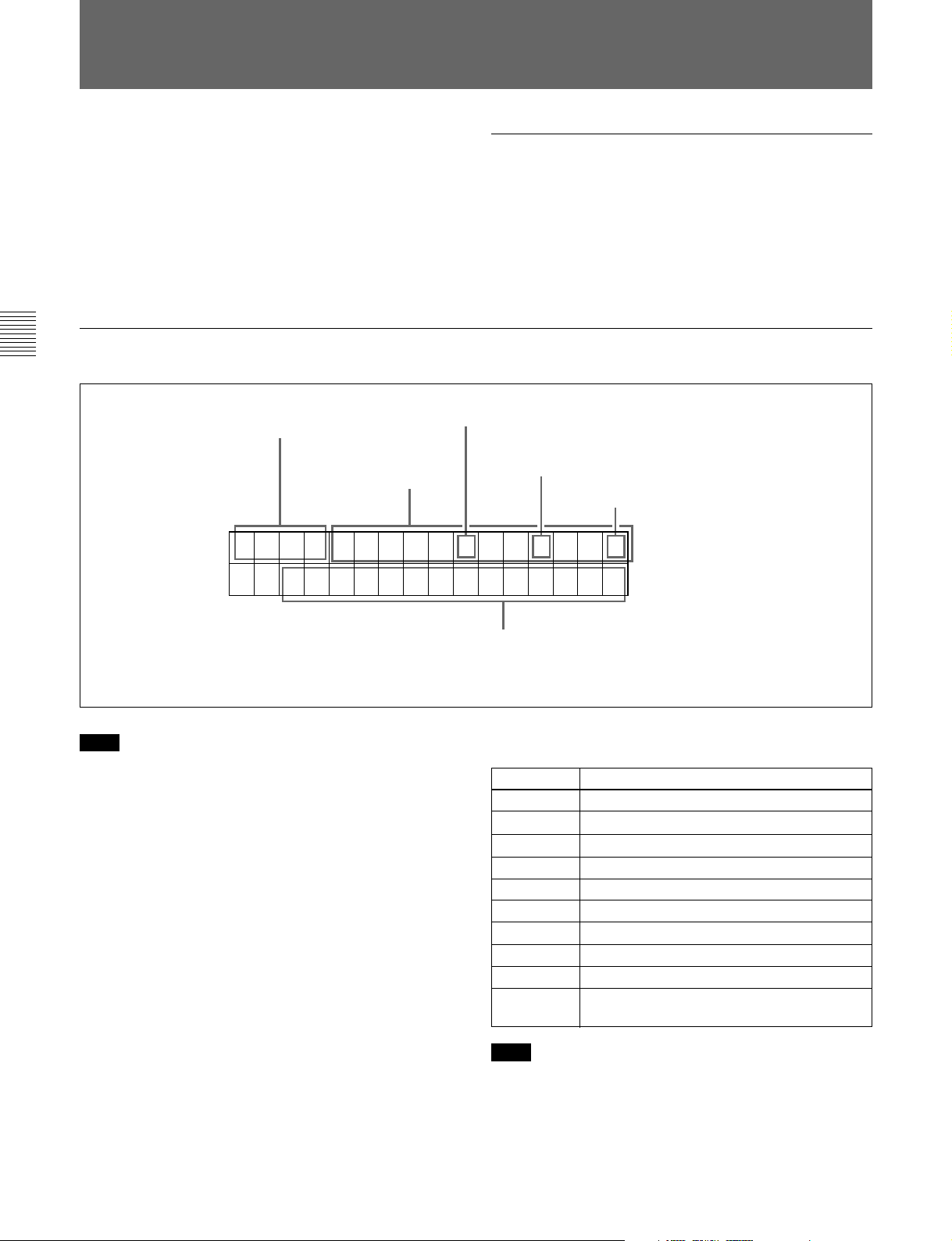
3-4 Superimposed Character Information
3-4 Superimposed Character Information
When F4 (CHARA) in function menu page 4 is set to
ON, the video signal output from the COMPOSITE
VIDEO OUTPUT 3 (SUPER) connector or the SDI
OUTPUT 3 (SUPER) connector contains
superimposed character information, including time
code, menu settings, and alarm messages.
Information displayed
Chapter 3 Preparations
Adjusting the character display
You can adjust the position, size and type of the
superimposed characters using setup menu items 002,
003, 005, 009, and 011.
For details, see Section 8-3 “Items in the Basic Setup
Menu” (page 8-5).
1 Type of time data
Time data
2 Time code reader drop frame mark
(for 525-line mode only)
3 Time code generator drop frame mark (for
525-line mode only)
4 VITC field mark
TCR . 23 : 5 9 . 4 0 . 1 8 *
SHUTTLE ST I LL
Note
The display shown above corresponds to the factory
default settings of the unit.
Changing the setting of setup menu item 005 allows
different time data to be displayed in the lower line of
the display.
For details, see Section 8-3 “Items in the Basic Setup
Menu” (page 8-5).
5 Operation mode
1 Type of time data
Display
CTL CTL counter data
TCR LTC reader time code
UBR LTC reader user’s bits
TCR. VITC reader time code
UBR. VITC reader user’s bits
IN IN point
OUT OUT point
AI Audio IN point
AO Audio OUT point
DUR Duration between any two of the four edit
Note
Meaning
points (IN, OUT, audio IN, audio OUT)
If the time data or user’s bits cannot be read correctly,
they will be displayed with an asterisk. For example,
“T*R”, “U*R”, “T*R.” or “U*R.”.
3-6 Chapter 3 Preparations
Page 31

2 Time code reader drop frame mark (for 525-line
mode only)
“.”: Indicates drop frame mode
“:”: Indicates non-drop-frame mode
3 Time code generator drop frame mark (for 525line mode only)
“.”: Indicates drop frame mode (factory preset)
“:”: Indicates non-drop-frame mode
4 VITC field mark
“ ” (blank): Fields 1 and 3 (for 525/60 mode) or
fields 1, 3, 5 and 7 (for 625/50 mode)
“ * ”: Fields 2 and 4 (for 525/60 mode) or fields 2, 4,
6 and 8 (for 625/50 mode)
5 Operation mode
The field is divided into three blocks, A, B and C.
• Block A displays the operation mode.
• Block B displays the servo lock status or tape speed.
• Block C displays a
mark to indicate an edit section
during automatic editing, or the section between the
IN and OUT points in auto feed playback.
A
B
C
Display
Block A Block B
SPD (speed) Feed playback speed setting
FEED (speed) During feed playback (speed
A-FEED During auto feed playback, or
A-FEED (speed) During auto feed playback, or
TAPE UNTHREAD Cassette is not loaded.
STANDBY OFF Standby off mode
T.RELEASE Tape tension released
STOP Stop mode
F.FWD Fast forward mode
REW Rewind mode
PREROLL Preroll mode
PLAY Playback mode (servo
PLAY Playback mode (servo locked)LOCK
PLAY Variation
from normal
speed (%)
JOG STILL A still picture in jog mode
JOG FWD Jog mode in forward direction
JOG REV Jog mode in reverse direction
SHUTTLE (Speed) Shuttle mode
VAR (Speed) Variable speed mode
DMC (Speed)
DMC-SPD (Speed) DMC initial speed setting
PLY-SPD Variation
from normal
speed
Operation mode
(+1.00 or +2.00 (BKMW-105
installed))
display same as during setting)
cue up
feed playback (speed display
same as during setting)
unlocked)
Capstan override mode
page 4-5)
a)
DMC playback mode
Tape speed override mode
(when “TSO” is selected in
setup menu item 111)
(see
Chapter 3 Preparations
a) Initial speed settings or stored speed settings
Chapter 3 Preparations 3-7
Page 32

3-5 Cassettes
3-5 Cassettes
This unit uses the following MPEG IMX cassettes for
playback.
The following tapes can also be used for playback.
Chapter 3 Preparations
• Digital Betacam cassettes
• Betacam SX cassettes
• Betacam SP cassettes (metal tape)
• Betacam cassettes (oxide tape)
3-5-1 Cassette Types
MPEG IMX cassettes
Small cassettes BCT-6MX/12MX/22MX/32MX/60MX
Large cassettes BCT-64MXL/94MXL/124MXL/184MXL
3-5-2 Inserting and Ejecting Cassettes
It is not possible to insert or eject a cassette unless the
unit is powered on.
Inserting a cassette
1
EJECT button
2
Small cassette
Large cassette
PLAY
STANDBY
F FWDREW
STOP
STANDBY button
STOP button
1 Turn the POWER switch on.
2 Check the following points, then insert the cassette
in the orientation shown in the figure.
• Check that message “ERR-10” is not shown in
the time data/menu display section.
• Check that there is no slack in the tape.
The cassette is drawn into the unit, and the
STANDBY and STOP buttons light.
If message “ERR-10” appears in the time data/menu display
section, there is moisture condensation in the unit.
3-8 Chapter 3 Preparations
Page 33

Removing slack from the tape
Press in one of the reels with a finger, and turn gently
in the direction shown by the arrows until there is no
slack in the tape.
Ejecting a cassette
Press the EJECT button.
Note
Ejecting is a local operation. It is not possible to eject a
cassette in another unit by remote control.
If the tape slacks inside the unit, pressing the EJECT button
may not eject the cassette. For information about how to
remove the cassette in such a case, refer to Section 1-17 in
the Installation Manual.
Chapter 3 Preparations
3-5-3 Preventing Accidental Erasure of Recordings
To prevent a tape from being inadvertently erased,
press in the red record inhibit plug on the cassette.
Large cassette
Small cassette
Press in the red record inhibit plug. (“ON”)
Return this plug to its original position to enable recording
on the tape again. (“OFF”)
Chapter 3 Preparations 3-9
Page 34

Page 35

4-1 Preparations for Playback
This section describes preparations for video and audio
playback.
4-1-1 Switch and Menu Settings
Chapter 4 Playback
Before beginning playback, make necessary switch
and menu settings.
POWER switch: ‘ & ’ side (ON)
REMOTE buttons
(see page 2-2)
Audio signal selection buttons
Select the audio channel(s) to be monitored.
Z
For details on each setting, see the pages indicated in
parenthesis.
: off
CTL/TC
TC
(see page 2-5)
MENU
:
Chapter 4 Playback
PB controls
Adjust the audio playback levels.
(see page 2-5)
:
TCR setting
CTL/TC setting
(see page 7-3)
: Select the time code to be displayed.
(see page 7-3)
: Select the time data to be displayed.
Chapter 4 Playback 4-1
Page 36

4-1 Preparations for Playback
4-1-2 Time Data Selection
Displayed time data
Use the CTL/TC setting in function menu HOME page
to select one of CTL (control), time code, and user bit
values. When you select time code, the data displayed
is determined by the TCR setting (LTC/AUTO/VITC)
in function menu page 1 as follows.
TCR setting Displayed data
LTC
AUTO
VITC
LTC recorded on tape
LTC or VITC (automatically switched)
VITC recorded on tape
Chapter 4 Playback
Output time code
The setting of setup menu item 606 determines
whether the time code output from the TIME CODE
OUT connector is the time code generated by the
internal time code generator (REGEN), or the
playback time code (TAPE).
4-1-3 Playback With SDTI-CP Output
Irrespective of tape format, video and audio signals
can be played back only at normal playback speed.
4-2 Chapter 4 Playback
Page 37

4-2 Playback Procedures
This section describes the following types of playback
which the unit can carry out:
• Normal playback
Playback at normal (×1) speed
• Playback in jog mode
Variable speed playback, with the speed determined
by the speed of turning the search dial
• Playback in shuttle mode
Variable speed playback, with the speed determined
by the angular position of the search dial
• Playback in variable speed mode
Variable speed playback, with the speed finely
determined by the angular position of the search dial
• Playback using the capstan override function
The playback speed is adjusted temporarily according
to the angular position of the search dial, to align the
playback phase with that of another VTR.
• DMC Playback
Playback carried out at memorized varying speed.
4-2-1 Normal Playback
If you play back to the end of the tape
The tape is automatically rewound, and stops.
It is possible to disable the automatic rewind function by
changing the setting of setup menu item 125.
When using the Dolby noise reduction system
When using an analog Betacam cassette, you can use
Dolby C noise reduction for audio playback.
To activate the Dolby noise reduction system, set the
DOLBY of function menu page 4 to NR ON (see page
7-6).
4-2-2 Playback in Jog Mode
Chapter 4 Playback
In jog mode, you can control the speed of playback by
the speed of turning the search dial. The playback
speed range is ±1 times normal speed.
The playback speed range can be ±3 times normal speed by
changing the setting of setup menu item 116.
First insert a cassette.
For details of how to insert a cassette, see Section 3-5-2
“Inserting and Ejecting Cassettes” (page 3-8).
Cassette compartment
Z
STOP button
PLAY button
To start playback
Press the PLAY button.
Playback starts, the servo locks, and the SERVO
indicator lights.
To carry out playback in jog mode, use the following
procedure.
Z
1 1,2,3
1 Press the JOG button or search dial so that the JOG
button is lit.
Pressing the search dial toggles between jog mode
and shuttle mode.
2 Turn the search dial in the desired direction, at the
speed corresponding to the desired playback speed.
To stop playback
Press the STOP button.
Playback in jog mode starts.
(Continued)
Chapter 4 Playback 4-3
Page 38

4-2 Playback Procedures
Chapter 4 Playback
3 To stop playback in jog mode, stop turning the
search dial.
The function to toggle between jog mode and shuttle
mode each time the search dial is pressed can be
disabled by changing the setting of setup menu item
101.
4-2-3 Playback in Shuttle Mode
In shuttle mode, you can control the speed of playback
by the angular position of the search dial. The range
of playback speed is as follows:
• Using a Digital Betacam tape: ±50 times
• Using an MPEG IMX tape: ±60 times
• Using a Betacam SX tape: ±60 times
• Using an analog Betacam tape: ±35 times (for 525/60
mode) or ±42 times (for 625/50 mode)
There are detents on the search dial at the still position
and at ±5 times normal speed.
To carry out playback in shuttle mode, use the
following procedure.
Z
The function to toggle between jog mode and shuttle
mode each time the search dial is pressed can be
disabled by changing the setting of setup menu item
101.
To return to normal-speed playback
Press the PLAY button.
To alternate between normal-speed playback
and shuttle mode playback
Set the search dial to the position corresponding to the
desired shuttle playback speed, then switch between
normal-speed playback and shuttle playback by
pressing the PLAY and SHUTTLE buttons alternately.
For intermittent shuttle mode playback, press the
STOP and SHUTTLE buttons alternately.
4-2-4 Playback in Variable Speed Mode
In variable speed mode, you can finely control (51
steps) the playback speed in the following speed
ranges depending on the tape format.
Digital Betacam: –1 to +3 times normal speed
MPEG IMX: –1 to +3 times normal speed
Betacam SX: –1 to +2 times normal speed
Betacam/Betacam SP: –1 to +3 times normal speed
There are detents on the search dial at the still position
and at ±1 times normal speed.
To carry out playback in variable speed mode, use the
following procedure.
1 1,2,33
1 Press the SHUTTLE button or search dial so that
the SHUTTLE button is lit.
Pressing the search dial toggles between jog mode
and shuttle mode.
2 Turn the search dial to the desired angle
corresponding to the desired playback speed.
Playback in shuttle mode starts.
3 To stop playback in shuttle mode, return the search
dial to the center position, or press the STOP
button.
4-4 Chapter 4 Playback
Z
1 2,33
1 Press the VAR button, turning it on.
Page 39

2 Turn the search dial to the desired angle
corresponding to the desired playback speed.
Playback in variable speed mode starts.
3 To stop playback in variable speed mode, return
the search dial to the center position, or press the
STOP button.
To return to normal-speed playback
Press the PLAY button.
1 (A) Hold down the PLAY button, and turn the
search dial in the desired direction to adjust the
playback speed.
The range of speed adjustment is ± 15% in
steps of 1%.
(B) Hold down the PLAY button, and press the
TRIM buttons to adjust the playback speed.
The playback speed can be adjusted to ± 8%
only.
The SERVO indicator goes off.
To alternate between normal-speed playback
and variable speed mode playback
Set the search dial to the position corresponding to the
desired variable playback speed, then switch between
normal-speed playback and variable speed playback by
pressing the PLAY and VAR buttons alternately.
For intermittent variable speed mode playback, press
the STOP and VAR buttons alternately.
4-2-5 Playback Using the Capstan Override Function
You can use the capstan override function to adjust the
playback speed temporarily. This function is
convenient for playback phase synchronization with
another VTR playing back the same program.
Two types of playback operation are available using
the capstan override function (capstan
override playback).
2 When the adjustment is completed, release the
PLAY button.
The tape transport returns to normal speed, and the
SERVO indicator comes on again.
To perform continuous capstan override
playback
Z
32
Chapter 4 Playback
To perform temporal capstan override
playback
Z
1 Set setup menu item 111 (TSO PLAY) to TSO.
2 Hold down the DMC EDIT button and turn the
MULTI CONTROL knob to select the playback
speed.
The selected playback speed is displayed in time
data display area 2 on the lower control
panel of this unit as well as in the character
information display on the monitor screen.
3 Press the PLAY button while holding down the
1(A)1(B) 2
DMC EDIT button.
(Continued)
Chapter 4 Playback 4-5
Page 40

4-2 Playback Procedures
Chapter 4 Playback
4 Press the PLAY button or perform any other
operation to exit the tape speed override mode.
See Section 8-2 “Setup Menu Operations” (page 8-2) for
details of setup menu operations.
For details of character information displayed on the video
monitor screen, see the descriptions of F4 (CHARA) in
function menu page 4 (page 7-6) and setup menu item 005
(page 8-5).
Carrying out playback in feed mode
Use the following procedure to carry out feed mode
playback.
Speed display area
Z
2 3 1
1 Hold down the DMC EDIT button, and turn the
search dial to set the playback speed.
When BKMW-105 option is installed
In MPEG IMX playback, you can set the feed
mode playback speed to 1 or 2 times normal speed
by rotating the MULTI CONTROL knob with the
DMC EDIT/FEED button held down. If the option
is not installed, feed mode playback speed is 1
times normal speed.
Auto feed playback
Auto feed playback is a function for feed mode
playback of the segment between a specified IN point
and OUT point.
By connecting this unit to a recorder VTR with a
RECEIVE STANDBY function (MAV-555/2000 etc.)
via the SDTI-CONTROL PANEL interface and
executing auto feed playback on this unit, you can
record the interval between the IN and OUT points on
the recorder.
1 On the HOME page of the function menu, set F4
(CTL/TC) to TC.
2 Start playback and, with the ENTRY button held
down, press the STUNT IN button at the point
where you want to set the IN point. To set the OUT
point, press the STUNT OUT button with the
ENTRY button held down.
3 With the DMC EDIT button held down, press
LEARN button. (Before starting, refer to step 1 of
the previous section “Carrying out playback in
feed mode” and set the feed mode playback speed.)
The VTR prerolls to a point 5 seconds before the
IN point (this can be changed with item 001 of the
basic menu) and starts auto feed playback.
Playback stops after postroll for 2 seconds beyond
the OUT point.
The segment between the IN and OUT points is
recorded on the recorder.
2 Hold down the DMC EDIT button, and press the
PLAY button.
Both buttons light, and playback in feed mode
starts.
3 Where you wish to stop playback, press the STOP
button.
Playback stops.
4-6 Chapter 4 Playback
Page 41

4-3 Dynamic Motion Control (DMC) Playback
This section describes dynamic motion control (DMC)
playback.
4-3-1 Overview
DMC playback allows you to vary the playback speed
for a certain section of a tape, in variable speed mode
(from –1 to +3 times normal speed for digital Betacam
playback, from –1 to +3 times normal speed for MPEG
IMX playback, from –1 to +2 times normal speed for
Betacam SX playback, or from –1 to +3 times normal
speed for analog Betacam playback), and store the
varying speed in memory for later playback at the
same varying speed.
On-air start point Preroll point Speed variation start point Speed variation end point On-air end point
Waiting for the on-air cue
before starting DMC
playback
Press the CUE/PLAY button
again at the on-air cue.
Starting DMC playback
immediately after preroll
Stop
Press the CUE/PLAY button.
Normal speed
playback
Press the LEARN button.
For example, during a live broadcast of a sporting
event you can set the start and end points of highlights
and then provide immediate DMC playback of those
highlights.
During DMC playback the tape moves as shown in the
following figure.
DMC playback
Normal speed playback
Stop
Chapter 4 Playback
Normal speed
playback
4-3-2 Storing a Varying Playback Speed in Memory
To store the playback speed for DMC playback, use
the following procedure.
Note
Make sure that the TSO PLAY of setup menu item 111
is set to DIS beforehand.
DMC playback Normal speed playback
Z
251,4 733,4,6
1 Press the DMC EDIT button, turning it on.
(Continued)
Chapter 4 Playback 4-7
Page 42

4-3 Dynamic Motion Control (DMC) Playback
Chapter 4 Playback
2 Either while playing back the recorded tape, press
the ENTRY button and one of the following
buttons simultaneously, to set the start and end
points.
• On-air start point: PLAY IN button
• Speed variation start point: STUNT IN button
• Speed variation end point: STUNT OUT button
• On-air end point: PLAY OUT button
Each press turns the corresponding button on.
3 Press the search dial or the SHUTTLE button or
VAR button to enter shuttle/variable speed mode.
The SHUTTLE/VAR indicator lights.
4 Holding down the DMC EDIT button, turn the
search dial, to set the initial speed at the playback
start point.
The speed you set appears in the speed indication
area. During this period the tape does not move.
When the initial speed setting is complete, release
the DMC EDIT button.
5 Press the LEARN button.
To amend the stored speed variation
Press the LEARN button.
The interval between the speed variation start and end
points is automatically played back at the stored speed.
Operate the search dial as required, to adjust the
playback speed.
Setting the initial speed to normal speed
In step 4, press the PLAY button.
4-3-3 Executing DMC Playback
There are two methods of starting DMC playback.
• Starting playback at the on-air cue from the on-air
start point
• Starting playback immediately after preroll
Note
To avoid operating mistakes we recommend that you
use the VTR in standalone mode when carrying out
DMC playback.
To start playback at the on-air cue from the
on-air start point
Use the following procedure.
The tape is prerolled and played back at normal
speed from the on-air start point to the speed
variation start point. On passing the speed variation
start point, the MEMORY indicator begins to
flash, and playback begins at the speed set in step
4.
6 Turn the search dial to vary the playback speed.
While the MEMORY indicator is flashing, the
speed variations are stored in memory. On passing
the speed variation end point, the MEMORY
indicator changes from flashing to continuously lit,
and the variable speed storing ends.
7 Press the STOP button to stop the tape.
If the MEMORY indicator lights continuously
before the speed variation end point
This indicates that the memory became full at that
point. It is therefore not possible to record more speed
variation. The maximum capacity is a duration of 120
seconds.
Z
1,2
1 Press the CUE/PLAY button.
The CUE/PLAY button lights, and the tape is cued
up to the on-air start point. After the tape is cued
up, the CUE/PLAY button flashes.
4-8 Chapter 4 Playback
Page 43

2 At the moment the on-air cue is given, press the
CUE/PLAY button once more.
The CUE/PLAY button lights, and playback starts
at standard speed.
Between the speed variation start and end points,
DMC playback is carried out at the stored speed,
and then playback continues at normal speed and
the tape stops at the on-air end point.
To start playback immediately after preroll
Press the LEARN button.
The LEARN button lights, and after preroll, DMC
playback is carried out for the section from the speed
variation start point, then playback continues at normal
speed from the speed variation end point.
To stop the tape during DMC playback
Press the STOP button.
To exit DMC playback mode
Press the DMC EDIT button and the DELETE button
simultaneously.
Chapter 4 Playback
Chapter 4 Playback 4-9
Page 44

Page 45

5-1 Overview
Chapter 5 Shot Mark Function
This unit can record shot marks or use shot marks
recorded in MPEG IMX or Betacam SX format.
Types of shot mark
This unit supports the following three types of shot
mark. This chapter describes recording start marks and
Shot mark type
Recording start mark Automatically written at the
Shot mark 1 and
shot mark 2
Post mark Not written
Writing on a camcorder,
etc.
start of recording.
Written by a manual shot
mark operation during
recording or editing.
(Written only on this unit)
Writing on this unit
Written by a button operation during playback,
while stopped, or during a search.
First, the shot mark functions of this unit are described
in simple terms.
Reading shot marks
This unit reads in shot marks written on a tape and
stores them in memory. (To a maximum of 200)
Once this data is stored in this unit, it is preserved even
when the power is turned off.
Shot marks are indications at desired points on a tape
which enable faster cuing.
post marks, treating them as varieties of shot marks.
Modifying and
erasing on this unit
—
—
Possible (erasure
only)
Possible
Cuing up to shot marks
By selecting a desired shot mark from the shot mark
list, you can cue up immediately to that position. By
means of a button operation, you can also cue up to the
shot marks adjacent to the current tape position (index
function).
Shot data display
Chapter 5
Shot Mark Function
Writing and erasing shot marks
On this unit, whereas you can erase any types of shot
marks, it is not possible to write any shot marks other
than post marks.
Shot mark list operations
On the monitor, you can display a list of the shot
marks read in by this unit, select required shot marks,
delete shot marks, and so on. You can also add a
memo mark (#) to a shot mark in the list.
During tape playback, you can add virtual shot marks
to the list. This is not written on the tape itself.
When the tape includes shot data (camera, time, and
other information captured at the time of shooting),
you can read this in, and display the details on a
monitor. It is also possible to display the shot mark list
and shot data simultaneously.
Sorting shot marks by cassette
When the tape includes shot data, this unit recognizes
which cassette each shot mark comes from. You can
therefore sort the read-in shot marks by cassette in
time code order.
Chapter 5 Shot Mark Function 5-1
Page 46

5-2 Shot Mark Operation Menu
This section describes the settings in the shot mark
operation menu.
Displaying the shot mark operation menu
With the function menu HOME page showing in the
menu display, hold down the MARK button, and press
the F5 (MENU) button.
Chapter 5
Shot Mark Function
The following menu appears on the monitor.
SHOT MARKER
GO1:SEARCH TYPE - all
GO2:LISTING TYPE
Z
F5 (MENU) button
MARK button
Details of the shot mark operation menu
The shot mark operation menu comprises two items,
G01 and G02. The detailed contents appear in the
following table.
Item
number
G01
G02 LISTING
Item name Settings
SEARCH
TYPE
TYPE
Select which shot mark type the
index function searches for, from
the following possibilities:
all
rec start mark
shot mark 1
shot mark 2
post mark
For each type of shot mark,
select whether to read into the
list (ON) or not read (OFF):
rec start mark
shot mark 1
shot mark 2
post mark
Changing the menu settings
The basic procedure for accessing menu items and
changing settings is the same as for the setup menus.
Note, however, the operations in “To change the
settings of menu items with sub-items” (page 8-3) for
item G02.
Similarly to the setup menu, the shot mark operation menu is
configured so that its current settings as well as menu banks
are saved separately for 525-line and 625-line modes. For
the menu bank operation of the shot mark operation menu,
the same procedure is used as that of the setup menu.
For details of the setup menu configuration and operations,
see Section 7-1 “Setup Menu Configuration” (page 8-1) and
Section 8-2 “Setup Menu Operations”(page 8-2),
respectively.
5-2 Chapter 5 Shot Mark Function
Page 47

5-3 Shot Mark Operations
This section describes the operations concerning
reading and writing shot marks. Note that the
following operations cannot be carried out by remote
control.
5-3-1 Reading Shot Marks
To read in shot marks
With a cassette loaded, hold down the LIST button and
press the F FWD or REW button.
Z
Reading shot marks from more than one
cassette
After changing the cassettes, carry out the reading
operation again.
Data written in the new cassette will be added as long
as the total does not exceed 200 shot marks. For
example, if 190 shot marks have already read in, only
10 shot marks will be read from the new tape.
In the shot mark list (see page 5-4) the data from
different cassettes is separated by a row of dashes.
5-3-2 Writing Post Marks
When this unit is in any of the playback, stop, or
search modes, you can write a post mark only.
Chapter 5
Z
F FWD button
REW button
LIST button
While the shot marks are being read in, the F FWD or
REW button flashes.
The unit searches to the end of the tape, then rewinds
automatically.
For the procedure for displaying a list of shot marks read
in, see page 5-4.
Note
It is only possible to read in a maximum of 200 shot
marks.
When 200 shot marks have been read in, the control
panel display shows the message “S-LIST FULL”, and
the reading stops.
To cancel the message, press one of the tape transport
buttons.
Shot Mark Function
ENTRY button
MARK button
REC/ERASE indicator
1 Hold the MARK button down for at least 2
seconds.
The REC/ERASE indicator lights.
2 At the position you wish to write the mark, hold
down the ENTRY button and press the MARK
button.
A post mark is written the instant you pressed the
MARK button.
To stop reading
Press the STOP button.
While the mark is being written, the message
“RECORD SHOT MARK” appears on the
monitor, and the REC/ERASE indicator flashes.
Chapter 5 Shot Mark Function 5-3
Page 48

5-3 Shot Mark Operations
Erasing a shot mark
Select the shot mark from the shot mark list, and then
carry out the deletion operation.
For details of the procedure, see page 5-5.
5-3-3 Shot Mark List Operations
Displaying the shot mark list
Hold down the ENTRY button and press the LIST
button.
Chapter 5
Shot Mark Function
Example of list display
The following figure shows how the list is organized.
Shot mark number of current cursor
position / total number of stored shot
marks
Separator
between read-in
groups of shot
marks
Cursor (current
shot mark position)
Position in list
Z
SHOT MARKER
(011/180)
NO. TIME CODE
---------------------------*011 S1 10:04:05:11
012 R 10:05:35:24
013 V 10:07:05:02
--------------------------- 014 R 10:08:35:04
015 S2 10:09:05:11
016 R 10:10:35:24
017 #R 10:10:36:00
Time code
Shot mark type
R: recording start mark
S1: shot mark 1
S2: shot mark 2
V: virtual shot mark
P: post mark
#: memo mark
ENTRY button
LIST button
All of the shot mark types for which item G02 in the
shot mark operation menu is set to “ON” appear in the
list. If you do the same operation again, the list display
disappears.
While the shot mark list is displayed, the function
menu display changes as follows.
SHT
MRK
SETING EXITMEMO SELECT DELETE
Selecting a shot mark
Turn the MULTI CONTROL knob to align the asterisk
cursor with the desired shot mark.
Entering virtual shot marks
When the REC/ERASE indicator is off, hold down the
ENTRY button and press the MARK button.
Z
ENTRY button
MARK button
5-4 Chapter 5 Shot Mark Function
Page 49

A virtual shot mark appears on the monitor as “V-
MARK xxx” (xxx is the number). This is not written to
the tape.
After entering a virtual shot mark, if you change the
cassette or power the unit off, it appears in the list as
the first shot mark of the next group read in.
Deleting a shot mark from the list
To delete a shot mark or the shot mark list, you can use
the F2 (SELECT) button instead of the MARK button,
and the F3 (DELETE) button instead of the DELETE
button.
Adding a memo mark (#)
Select the shot mark to which you wish to add the
memo mark, then press the F1 (MEMO) button.
Repeat this operation to remove a memo mark.
Selecting the types of shot mark to be
read in the list
For each of the types of shot mark (recording start
mark, shot mark 1, shot mark 2, and post mark) you
can specify whether it is read in.
In item G02 of the shot mark operation menu, set the
required types to “ON”.
For details of the menu, see page 5-2.
You can also use the following procedure.
1 With the shot mark list displayed, press the F5
(SETING) button.
You can now select the shot mark types.
The function menu display changes as follows.
SHT
MRK
EXITPREV NEXT OFF ON
To delete an individual shot mark
Use the following procedure.
Z
312
1 With the shot mark list displayed, select the shot
mark to be deleted using the MULTI CONTROL
knob.
2 Hold the MARK button down.
While you hold down the button, an “X” appears
after the selected shot mark number, indicating that
it will be deleted.
To delete more than one shot mark, while holding
down the MARK button turn the MULTI
CONTROL knob to select all of the shot marks.
Chapter 5
Shot Mark Function
2 Press the F1 (PREV) or F2 (NEXT) button to
select a shot mark type.
3 Press the F4 (ON) or F3 (OFF) button to switch
between ON (displayed) and OFF (not displayed).
4 To return to the shot mark list, press the F6 (EXIT)
button.
3 With the MARK button held down, press the
DELETE button.
This deletes the shot marks which were marked by
an “X”.
To delete the entire list
Hold down the DELETE button and press the LIST
button.
This deletes all shot marks from the list. This does not
erase marks from the tape.
Chapter 5 Shot Mark Function 5-5
Page 50

5-3 Shot Mark Operations
Erasing shot marks from the tape
To erase a shot mark, use the following procedure.
Note
Once you erase a shot mark from the tape, it cannot be
read back in.
1 With no shot mark list displayed, hold the MARK
button down for at least 2 seconds.
The REC/ERASE indicator lights, indicating that
you can rewrite or erase shot marks.
2 Display the shot mark list.
3 Turn the MULTI CONTROL knob to select on the
list the shot mark you wish to erase.
Chapter 5
Shot Mark Function
4 Press the DELETE button and MARK button
simultaneously.
During the erasure process the message “ERASE
SHOT MARK” appears, and the REC/ERASE
indicator flashes.
5-3-4 Cuing Up to Shot Marks
Cuing up to a selected shot mark
Use the following procedure.
Z
MARK button
12
F FWD button
REW button
1 Select the desired shot mark from the shot mark
list.
2 Press the PREROLL button.
5 When the shot mark has been erased, close the shot
mark list.
6 Hold down the MARK button for at least 2
seconds, to turn off the REC/ERASE indicator.
Cuing up to shot marks adjacent to the
current tape position (index function)
1 In item G01 of the shot mark operation menu
(page 5-2), select one of recording start mark, shot
mark 1, shot mark 2, and post mark, or select all.
2 Holding down the MARK button, press the F FWD
button or REW button.
While the tape is moving the F FWD button or
REW button flashes.
When the shot mark is detected, its type is
displayed in time data display area 2 on the
lower control panel and in the character
information display on the monitor screen.
For details of character information display on the
monitor screen, see F4 (CHARA) in function menu page
4 (page 7-6) and setup menu item 005 (page 8-5).
5-6 Chapter 5 Shot Mark Function
Note
You cannot use the above procedure to cue up to a
virtual shot mark.
Page 51

5-3-5 Reading In Shot Data
When there is shot data (time, device, and other
information about the shooting) written on the tape,
you can read it in and display it on the monitor.
Displaying the shot data
Displaying the shot data on the shot mark
list
Turn the MULTI CONTROL knob to position the
cursor on a separator in the shot mark list.
If there is shot data recorded when the immediately
following shot mark was written, it appears in the
display as shown below.
Holding down the ENTRY button, press the PLAY
button.
Z
PLAY button
ENTRY button
The tape is played back, and the shot data displayed.
To delete the shot data
Once again hold down the ENTRY button, and press
the PLAY button.
Model name (4 characters)
Model number (4 digits)
Serial number (6 digits)
Shot data
First shot
mark in the
group
SHOT MARK
(---/180)
NO. TIME CODE
*012345-DNW_-0123-4567011 S1 10:04:05:11
012 R 10:05:35:24
013 V 10:07:05:02
---------------------------014 R 10:08:35:04
015 S2 10:09:05:11
016 R 10:10:35:24
017 R 10:10:36:00
Cassette number (4 digits)
You can sort the shot marks in the list, based on the shot
data. For details, see the next section.
Chapter 5
Shot Mark Function
Example of shot data display
The shot data display appears as shown below.
MODEL NAME DNW 0090
SERIAL NUMBER 010001
DATE 1998.05.11
TIME 12.55.10
CASSETTE NUMBER 0095
SHOT NUMBER 0052
ID1 AAAAAAAAAAAA
Camera IDs
Recording
time code
The details in the shot data depend on the shooting
conditions. If because of the devices used there is no
shot data on a part of the tape, it appears as blank.
ID2 BBBBBBBBBBBB
ID3 CCCCCCCCCCCC
ID4 DDDDDDDDDDDD
TCR 23:59:59:29
Chapter 5 Shot Mark Function 5-7
Page 52

5-3 Shot Mark Operations
5-3-6 Sorting Shot Marks
Based on shot data recorded on the tape, you can
separate the shot marks by cassette, and sort them in
time code sequence.
To sort the shot marks
Use the following procedure.
Chapter 5
Shot Mark Function
Cassette 2 (first time)
Cassette 2 (second time)
Z
Cassette 1
Cassette 3
321
Before sorting
SHOT MARKER
(---/180)
NO. TIME CODE
*012345-DNW_-0123-4567011 S1 10:04:05:11
---------------------------012 V 10:07:05:02
013 R 10:08:35:04
---------------------------014 S2 10:09:05:11
015 R 10:10:35:24
016 R 10:10:36:00
---------------------------017 R 10:05:35:24
1 With the shot mark list displayed, press the F5
(SETING) button.
2 Press the F2 (NEXT) button, and select SORTING
LIST.
3 Press the F4 (ON) button to change the setting to
ON.
Sorting starts. When it ends, the setting indication
returns to OFF.
For example, if shot marks have been read in twice
from the same cassette, these can be collated as shown
in the following figure.
After sorting
SHOT MARKER
(---/180)
NO. TIME CODE
*012345-DNW_-0123-4567011 S1 10:04:05:11
---------------------------012 S2 10:09:05:11
013 R 10:10:35:24
014 R 10:10:36:00
---------------------------015 R 10:05:35:24
016 V 10:07:05:02
017 R 10:08:35:04
Cassette 1
Cassette 3
Cassette 2 (first and second
times)
5-8 Chapter 5 Shot Mark Function
Shot marks from the cassette 2 read in twice are
collated, and arranged in time code sequence.
Page 53

6-1 Overview of Tele-File Functions
Chapter 6 Tele-File
Tele-File is a non-contact data carrier system.
Tele-File increases the efficiency of data management
and operations such as playback and editing by
enabling information to be exchanged between VTRs
with data reading and writing functions and cassettes
with Tele-File labels.
Memory label
Newly developed IC
The Tele-File system employs a newly developed
memory IC with the following features.
• Thin design: With a thickness of 0.5 mm, the IC can
be attached to cassettes as a memory label.
• Memory capacity: 1 KB/8 KB (user area,
rewritable)
• Data transfer speed: 100 kbps
• Security functions: Reading and writing
authorization can be controlled through multiple
passwords and permission settings.
Data management in clip units
In Tele-File, data is managed in units called “clips.” A
clip consists of the following data items, whose
settings can be displayed and changed.
• Cue point
• Write protect
• Mark
• Recording start point
• IN point
• OUT point
• Take number
• Cut number
• Scene number
• Comment
Data library management with handy
reader/writer
An optional handy reader/writer (supporting Memory
Stick) is available to facilitate data library
management.
Chapter 6
Tele-File
Chapter 6
Tele-File 6-1
Page 54

6-2 Opening the Tele-File Menu
Opening from the function menu
Display page 5 of the function menu in the menu
display section, and then press the F1 (TELE-F)
button.
The Tele-File menu opens.
For details about the function menu, see Chapter 7
“Function Menu” (page 7-1).
Opening automatically
When setup menu item 134 is set to ON, and when the
current function menu page is HOME, HOME2, or
page 1 to page 5, the Tele-File menu opens
automatically whenever a Tele-File label is detected on
a cassette loaded into the VTR.
For details about setup menu item 134, see Section 8-4
“Items in the Extended Setup Menu” (page 8-10).
Configuration of the Tele-File menu
The Tele-File menu has a tree structure, as illustrated
below.
When the menu first opens, the menu operation mode
is clip data display mode.
[Tele-File menu]
Clip data display mode
Attribute data display/
modify mode
Clip data modify mode
Undo check mode
Chapter 6
Tele-File
6-2
Chapter 6
Tele-File
Page 55

6-3 Tele-File Menu
6-3-1 Clip Data Display
How to read the display
Shown below are examples of the default menu
displays in the menu display section and the monitor
display.
Menu display section
Tele-File menu indicator
Data type indicator
Setting display area
TEL
Cue
SELECT
ATTRIB
E-F
HOME
Monitor display
F1 F2 F3 F4 F5 F6
Menu items (functions)
For more information about how to display menus on the
monitor, see the section “To display menus on the monitor”
(page 8-2).
UNDO WR/EXT
Chapter 6
Title
Final data recording date
Data type
Clip No. 0001
Clip No. 0002
Clip No. 0003
TELE-FILE : TEST 01
2001/07/21 No. 0001 48%
Cue Point WP Mark R
*00:00:02:10 ON KEEP @
00:00:31:10
00:00:57:10
Number of selected clip
Remaining memory percentage
a) The Tele-File memory always contains the attribute data so that this indication never shows “100%.”
Tele-File menu indicator
Indicates that the menu display section is currently
displaying the Tele-File menu.
Cue: Cue point
Protct: Write protected
Mark: Mark
R-Strt: Recording start point
Data type indicator
Indicates the type of data selected with the clip data
display mode. There are the following types.
IN: IN point
OUT: OUT point
Take: Take number
Cut: Cut number
Scene: Scene number
Comnt: Comment
Tele-File
a)
Chapter 6
Tele-File 6-3
Page 56

6-3 Tele-File Menu
Chapter 6
Tele-File
Setting display area
Displays the setting of the currently selected data type,
and a cursor (“*” or “>”).
The meaning of the cursor symbols is as follows:
*: Indicates that the mode is clip data display mode or
Menu items (functions)
Display menu items (functions).
These are common for all of the data items in clip data
display mode. The function assignments for each item
are as follows.
attribute data display/modify mode, and that data is
selected.
>: Indicates that the mode is clip data modify mode or
attribute data display/modify mode, and prompts for
data entry or modification.
Clip data display mode menu items
Item name Function
F1 (ATTRIB)
F2 (SELECT) Selects a data modification mode for the data selected in the clip. The cursor changes from “*” to “>”.
F3 (T) Selects data in a clip.
F4 (t) Selects data in a clip.
F5 (UNDO) Selects undo check mode. This button appears and is enabled when data has been modified after being
F6 (WR/EXT) Writes data and exits from the Tele-File menu (return to function menu page 5).
Selects attribute data display/modify mode.
For details about attribute data display/modify mode, see Section 6-3-5 “Displaying and Modifying
Attribute Data” (page 6-11).
Note
In the following cases, the SELECT item does not appear, and it is not possible to select a data
modification mode.
• When setup menu item 133 is set to REMOTE
• When the memory label itself is write protected
For more information about clip data modifications, see Section 6-3-3 “Modifying Clip Data” (page 6-7).
With each press, the “*” cursor moves to select the previous data item. The display scrolls to the left
when the cursor moves to data that is not currently displayed.
With each press, the “*” cursor moves to select the next data item. The display scrolls to the right when
the cursor moves to data that is not currently displayed.
read from the Tele-File label.
For more information about undo check mode, see Section 6-3-4 “Undo/Resume Functions” (page 6-10).
6-4
Chapter 6
Tele-File
Page 57

Title
2001/07/21 No. 0001 48%
Cue Point WP Mark R
TELE-FILE : TEST 01
00:00:02:10 *ON KEEP @
00:00:31:10
00:00:57:10
The title (maximum 14 characters) set in attribute data
display/modify mode.
Selected clip number
A 4-digit number representing the number of the
selected clip (with the “*” cursor).
Remaining memory percentage
The percentage of remaining memory (user area)
available for use.
If there is not sufficient free memory, the message
<<MEMORY FULL!!>> appears (stays lit for three
seconds) in time data display area 2 when you attempt
to add data.
Final data recording date
The data (year/month/day) on which data was most
recently recorded.
Data type
The data type. The displayed data is the same as the
data displayed in the menu display section, but some of
the captions are different. There are the following
types.
Cue Point: Cue point
WP: Write protected
Mark: Mark
R: Recording start point
IN Point: IN point
OUT Point: OUT point
Tk: Take number
Cut: Cut number
Scn: Scene number
Comment: Comment
Clip data No. 0001...
Data is displayed for 1 clip per line.
Clips are assigned continuous numbers, beginning with
No. 0001 for the clip on the top line.
To select clips
Rotate the MULTI CONTROL knob in clip data
display mode.
The data for the selected clip appears in the menu
display section, where it is selected.
In the monitor display, the “*” cursor moves up and
down as clips are selected.
Data which is not visible is selected and displayed
after scrolling.
TELE-FILE : TEST 01
2001/07/21 No. 0001 48%
Cue Point WP Mark R
Cursor
00:00:02:10 ON KEEP @
*00:00:31:10
00:00:57:10
To select data in a clip
In clip data display mode, press the F3 (T) or F4 (t)
button.
The “*” cursor moves and data is selected. Data which
is not visible is selected and displayed after scrolling.
(Scrolling)
Cursor
Chapter 6
Tele-File
Chapter 6
Tele-File 6-5
Page 58

6-3 Tele-File Menu
Moving the cursor directly
Regardless of the cursor’s current position, pressing
one of the following buttons moves the cursor directly
to the specified position in the same clip and displays
the data.
IN (video IN point) button: IN point data
OUT (video OUT point) button: OUT point data
MARK button: Cue point data
To display the duration
Press the IN (video IN point) and OUT (video OUT
point) buttons simultaneously. The cursor moves to the
IN point data of the same clip, and the duration
appears while the buttons are held down. If there is no
IN point or OUT point data, the duration is displayed
as 0:00:00:00.
6-3-2 Preroll and Cue Up Using Clip Data
To cue up the cue point, IN point, or OUT
point
1 Select a clip.
2 Press the PREROLL button while holding down
the IN (video IN point), OUT (video OUT point),
or MARK button.
The unit exits from the Tele-File menu and cues up
the position of the data selected in step 2 (the cue
point position if the MARK button was pressed).
Note
The unit does not preroll if there is no data for the
selected point.
Chapter 6
Tele-File
In clip data display mode, you can use clip data to
preroll and cue up.
To preroll to the cue point, IN point, or
OUT point
1 Select a clip.
2 Select the cue point, the IN point, or the OUT
point.
3 Press the PREROLL button.
The unit exits from the Tele-File menu and prerolls
to the position of the selected data.
The preroll time is according to the setting of setup
menu item 001.
Note
The unit does not preroll if there is no data for the
selected point.
6-6
Chapter 6
Tele-File
Page 59

6-3-3 Modifying Clip Data
To modify clip data, put the unit into clip data display
mode and then press the F2 (SELECT) button to put it
The function assignments for menu items in clip data
modification mode are as follows.
into clip data modification mode (the cursor changes to
“>”).
Clip data modification mode menu items
Item name Function
F1 (RETURN)
F2 (MODIFY) Changes the setting of the selected data, or makes a new setting.
F3 (DELETE) Deletes the data setting value. Enabled when cue point, IN point, OUT point, take number, cut number,
F4 (DEL LN) Deletes the selected clip.
F5 (INS LN) Inserts a clip at the cursor position.
HOME + F4
(DELETE ALL)
Returns to clip data display mode.
The function button changes according to the data type.
See the following for more information about how to set the various data types.
• Cue point, IN point, OUT point: “To set timecode data” (page 6-8)
• Write protect, mark, recording start point: “To make write protect, mark, and recording start point
settings” (page 6-9)
• Take number, cut number, scene number: “To make take number, cut number, and scene number
settings” (page 6-9)
• Comment: “To make comment settings” (page 6-10)
scene number, or comment data is selected.
A confirmation message appears. Press one of the following buttons to confirm or cancel the operation.
• F1 (CANCEL): Cancels the deletion and returns to clip data display mode.
• F2 (OK): Executes the deletion and returns to clip data display mode.
A confirmation message appears. Press one of the following buttons to confirm or cancel the operation.
• F1 (CANCEL): Cancels the deletion and returns to clip data display mode.
• F2 (OK): Executes the deletion and returns to clip data display mode.
A confirmation message appears. Press one of the following buttons to confirm or cancel the operation.
• F1 (CANCEL): Cancels the insertion and returns to clip data display mode.
• F2 (OK): Executes the insertion and returns to clip data display mode.
Deletes all clips.
A confirmation message appears. Press one of the following buttons to confirm or cancel the operation.
• F1 (CANCEL): Cancels the deletion and returns to clip data display mode.
• F2 (OK): Executes the deletion and returns to clip data display mode.
Chapter 6
Tele-File
Chapter 6
Tele-File 6-7
Page 60

6-3 Tele-File Menu
To add and delete clips
To add clips
1 Rotate the MULTI CONTROL knob to move the
“*” cursor to the position where you want to insert
the clip.
2 Press the F2 (SELECT) button.
The unit enters clip data modification mode.
3 Press the F5 (INS LN) button.
A confirmation message “INSERT CLIP OK?”
appears.
4 Press the F2 (OK) button.
The clip is added at the position to which you
moved the cursor in step 1.
To delete clips
To set timecode data
Proceed as follows to make or change settings for cue
point, IN point, and OUT point data.
1 Select a clip.
2 Select cue point, IN point, or OUT point.
3 Press the F2 (SELECT) button.
The unit enters clip data modification mode.
4 Press the F2 (MODIFY) button.
The two most significant digits begin to flash, and
the data can be set or modified.
5 Press the F3 (T) or F4 (t) button until the digit
that you want to set starts flashing.
6 Rotate the MULTI CONTROL knob to make the
setting.
Chapter 6
Tele-File
1 Select the clip to delete.
2 Press the F2 (SELECT) button.
The unit enters clip data modification mode.
3 Press the F4 (DEL LN) button.
A confirmation message “DELETE THIS CLIP
OK?” appears.
4 Press the F2 (OK) button.
The clip selected in step 1 is deleted.
To display the offset from the previous setting
value
The offset is displayed as long as you hold down
the F2 (OFFSET) button.
7 Repeat steps 5 and 6 until you have set all the
required digits.
8 Press the F5 (SET) button.
The setting is confirmed and the unit returns to clip
data display mode.
To cancel the setting or modification and return
to clip data display mode
Press the F1 (CANCEL) button.
6-8
Chapter 6
Tele-File
Page 61

To set the set or modified data as other time
data
Press the F6 (SET TO) button and select the time
data (cue point, IN point, or OUT point), and then
press the F5 (SET) or F6 (SET NL) button. The
position where the data is set differs as follows,
depending on the button pressed.
• F5 (SET): The data is set in the selected time
data position.
• F6 (SET NL): A new clip is added at the lowest
line and the time data is set at the selected data
position in the new clip.
To make write protect, mark, and
recording start point settings
To make take number, cut number, and
scene number settings
Proceed as follows to make take number, cut number,
and scene number settings.
1 Select a clip.
2 Select take number, cut number, or scene number.
3 Press the F2 (SELECT) button.
The unit enters clip data modification mode.
4 Press the F2 (MODIFY) button.
Proceed as follows to make write protect, mark, and
recording start point settings.
1 Select a clip.
2 Select write protect, mark, or recording start point.
3 Press the F2 (SELECT) button.
The unit enters clip data modification mode.
4 Press the F2 (MODIFY) button.
The data entry area begins to flash, and the data
can be set.
5 Select the data by pressing the F3 (+) or F4 (−)
button or rotating the MULTI CONTROL knob.
6 Press the F2 (SET) button.
The data setting is confirmed and the unit returns
to clip data display mode.
The most significant digit begins to flash, and the
data can be set.
5 Press the F3 (T) or F4 (t) button until the digit
that you want to set starts flashing.
6 Rotate the MULTI CONTROL knob to make the
setting.
7 Repeat steps 5 and 6 until you have set all the
required digits.
8 Press the F2 (SET) button.
The setting is confirmed and the unit returns to clip
data display mode.
Chapter 6
Tele-File
Chapter 6
Tele-File 6-9
Page 62

6-3 Tele-File Menu
Chapter 6
To make comment settings
Proceed as follows to make comment settings.
1 Select a clip.
2 Select comment.
3 Press the F2 (SELECT) button.
The unit enters clip data modification mode.
4 Press the F2 (MODIFY) button.
The data entry area begins to flash, and the data
can be set.
5 Enter a character by rotating the MULTI
CONTROL knob.
6 Press F4 (t) button to move to the next character
place.
7 Repeat steps 5 and 6 until you have entered the
entire comment.
6-3-4 Undo/Resume Functions
Undo function
The undo function cancels all modifications and
returns the data to the state it was in when first read.
Press the F5 (UNDO) button in clip data display mode.
A confirmation message appears. Press the F2 (OK)
button to execute the undo and cancel all modifications
to the data.
Resume function
If you have not modified any data since the last
execution of the undo function, you can press the F5
(UNDO) button again. The button functions as a
resume button, which cancels the immediately
preceding undo.
Press the F5 (UNDO) button in clip data display mode.
A confirmation message appears. Press the F2 (OK)
button to execute the resume and cancel the
immediately preceding undo.
Tele-File
To delete characters
Press the F3 (T) or F4 (t) button until the
character that you want to delete starts flashing,
and then press the F5 (DELETE) button.
To insert characters
Press the F3 (T) or F4 (t) button until the
character place after the place where you want to
insert starts flashing, and then press the F6
(INSERT) button.
8 Press the F2 (OK) button.
The comment is confirmed and the unit returns to
clip data display mode.
6-10
Chapter 6
Tele-File
Page 63

6-3-5 Displaying and Modifying Attribute Data
You can display and modify attribute data. The
example below shows attribute data displayed on the
monitor.
Video final recording date
Administrator data
Number of cue points
Memory size
Amount of memory used
Video final recording date
The most recent date (year/month/day) on which video
was recorded on the tape.
Title
The title (name assigned to Tele-File, etc., maximum
24 characters).
The title can be modified.
ID
The ID (unique number assigned to Tele-File,
maximum 24 characters).
The ID can be modified.
Administrator data
Data about the administrator of the cassette or tape
material (maximum 16 characters).
The administrator data can be modified.
Model name
The model name of the VTR that recorded most
recently to the tape.
Serial number
The serial number of the VTR that recorded most
recently to the tape.
TELE-FILE INFORMATION
*REC DATE 2001/07/21
TITLE TEST 01
ID
ADMIN
MODEL
SERIAL 00000
WRITE INHIBIT OFF
THREAD COUNT 00012
CUE POINT No. 0003
CONTROL MODE panel
SIZE 01024 USED 0270
Write inhibit setting
Whether the entire Tele-File is write inhibited.
The write inhibit setting can be modified.
Thread count
The thread count value recorded on the tape.
Number of cue points
The number of cue points recorded in the Tele-File.
You can check the cue point values in clip data display
mode.
Control mode
The setting of menu item 133.
For more information about menu item 133, see page 8-10.
Memory size
The size of the memory in the Tele-File (unit: bytes).
Amount of memory used
The amount of memory currently being used (unit:
bytes).
Chapter 6
Tele-File
Chapter 6
Tele-File 6-11
Page 64

6-3 Tele-File Menu
To modify attribute data
You can modify the title, ID, administrator data, and
write inhibit setting attributes.
However, the attributes cannot be modified when the
write inhibit setting is ON. Proceed as follows after
setting the write inhibit setting to OFF.
1 Rotate the MULTI CONTROL knob to select the
item.
The F2 (SELECT) button is enabled when you
select an item that can be modified (title, ID,
administrator data, and write inhibit setting).
2 Press the F2 (SELECT) button.
The data can be set or modified.
3 Rotate the MULTI CONTROL knob to set or
modify the data..
2 Press the F2 (OK) button.
All modifiable data is erased.
Note
In the following cases, the FORMAT item does not
appear, and it is not possible to select a data
modification mode.
• When setup menu item 133 is set to REMOTE
• When the memory label itself is write protected
For more information about clip data modifications, see
Section 6-3-3 “Modifying Clip Data” (page 6-7).
Chapter 6
Tele-File
4 Press the F2 (SET) button.
The change to the setting is confirmed.
Note
In the following cases, the SELECT item does not
appear, and it is not possible to select a data
modification mode.
• When setup menu item 133 is set to REMOTE
• When the memory label itself is write protected
For more information about clip data modifications, see
Section 6-3-3 “Modifying Clip Data” (page 6-7).
To format the Tele-File memory
You can format the Tele-File memory (erase all
modifiable data). However, the memory cannot be
formatted in the following cases.
• When the write inhibit setting is ON
• When the control protocol is “remote”
To format Tele-File memory, proceed as follows.
1 Press the F4 (FORMAT) button.
A confirmation message appears.
6-12
Chapter 6
Tele-File
Page 65

7-1 Overview
Chapter 7 Function Menu
The function menu allows you to make frequently
made settings, such as time code settings.
7-1-1 Function Menu Configuration
The function menu consists of six pages by factory
default: the HOME page and five pages numbered 1 to
5. You can also display the HOME2 page by setting
user-defined function keys. The following icons appear
at the left edge of the menu display section to denote
the current page.
: HOME page
1
: Page 1
1
: Page 2
2
: Page 3
3
: Page 4
4
: Page 5
5
: Page 6
6
: HOME 2 page
2
Each page has a menu display section made up of an
upper and lower part. The upper part displays the
menu items (functions) in the page, and the lower part
displays the menu item settings. The figure below
shows the menu display section in the HOME page.
HOME2 page (user-defined function keys)
Up to six function keys can be defined (i.e. six
functions can be assigned to the F1 to F6 buttons in the
HOME2 page).
You can select and define the following function keys:
• Functions selected from the function menu items in
the HOME page and menu pages 1 to 5
• Function key to display the setting for setup menu
item 211 (REMOTE1 PORT) and to carry out the
operation when the menu item setting is “panel”.
Note
By factory default, no function keys are defined in the
HOME2 page.
It is not possible to display the HOME2 page unless
you have defined at least one function key in that page.
For details on defining user-defined function keys in the
HOME2 page, refer to the Maintenance Manual Volume 1.
Page 6
You can define up to six setup menu items (assign six
setup menu items to the F1 to F6 buttons) and register
them on page 6.
Note
There is nothing defined on page 6 when the unit is
shipped from the factory.
Chapter 7
Menu items (functions)
CTL/TCTCMENU
HOME F1 F2 F3 F4 F5 F6
Settings (values)
In the figure above, TC (time code) is selected as the
setting for CTL/TC (time data selection), the menu
item for button F4. This manual refers to this as “F4
(CTL/TC) in function menu HOME page is set to TC.”
For more information about defining setup menu items for
page 6, refer to Volume 1 of the Maintenance Manual.
7-1-2 Using the Function Menu
To change a menu item setting
To change a menu item setting, press the
corresponding function button (F1 to F6) to display the
desired setting in the lower part of the menu display.
Each press of the button displays the next setting.
When a menu item setting flashes
Menu item settings flash to inform you that you can
change the setting value by rotating the MULTI
CONTROL knob.
Chapter 7
Function Menu 7-1
Function Menu
Page 66

7-1 Overview
To change the function menu page
Press either of the page buttons (V, v).
• The V button selects the next page in the order
HOMEt1t2t3t4t5tHOME...
• The v button selects the next page in the order
HOMEt5t4t3t2t1tHOME...
When there are setup menu definitions on page 6, page
6 is displayed between page 5 and the HOME page.
With one of menu pages 1 to 5 displayed, pressing the
HOME button changes the page to the HOME page.
Pressing the HOME button when the HOME or
HOME2 page is displayed changes the page to
HOME2 or HOME, respectively.
Settings which do not appear in the menu
display section
In the HOME page (see the figure in Section 7-1-1
“Function Menu Configuration”), the setting for F5
(MENU) does not appear in the menu display.When
you press the F5 button, the whole menu page changes
to allow you to set the item.
Chapter 7
Function Menu
7-2
Chapter 7
Function Menu
Page 67

7-2 Function Menu Item List
The function menu has the following items. In the “Setting” column of the table, the factory default
settings are indicated by an enclosing box.
HOME page
Item
F4 (CTL/TC) Selects the time data to display in time data display area 1
F5 (MENU) Puts the system into setup menu mode
Setting
(see page 2-6)
TC: Playback time code read by the internal time code reader. The LTC or VITC time data type indicator
(see page 2-6)
UB: User bits data of playback time code. The LUB or VIUB time data type indicator lights, depending on
whether the time code is LTC or VITC.
CTL : The running time of the tape being played back, as calculated from a count of CTL signals recorded
on the tape. The time is displayed in Hours:Minutes:Seconds:Frames format.
When the current setup menu settings are the same as the contents of any of menu banks 1 to 3, or the
factory defaults, the corresponding indication (1), (2), (3), or (dflt) appears.
(1): Same as menu bank 1.
(2): Same as menu bank 2.
(3): Same as menu bank 3.
(dflt): Same as factory defaults.
lights.
a)
a)
(see Chapter 8)
.
.
a) The selection of LTC or VITC depends on the setting of F6 (TCR) in function menu page 1 .
Page 1
Item Setting
F4 (DF)
F6 (TCR) Selects the type of time code to display in the time data display.
In 525/60 mode, selects either drop-frame mode or non-drop frame mode for the time code generator and
the CTL counter.
DF: Drop-frame mode
NDF : Non-drop frame mode
LTC: Display LTC.
AUTO : Display VITC when tape speed is 1/2 or less of normal speed, and LTC otherwise.
VITC: Display VITC.
Chapter 7
Function Menu
Chapter 7
Function Menu 7-3
Page 68

Chapter 7
7-2 Function Menu Item List
Page 2
Item Setting
F1 (V.PROC) Selects the control method for the internal digital video processor.
LOCAL : Change the settings of the internal digital video processor by using this function menu.
REMOTE: Use the optional BVR-50/50P Remote Control Unit to control the internal digital video
processor.
MENU: Change the settings of the internal digital video processor by using the MENU of the HOME page.
F2 (VIDEO) Sets the video signal output level (–∞ to +3 dB).
PRESET : Regardless of manually values, the video signal is set to the standard level.
Manual setting: With the displayed setting flashing, you can rotate the MULTI CONTROL knob to adjust
the value for the video signal output level.
F3 (CHROMA) Sets the chroma signal output level (–∞ to +3 dB).
PRESET : Regardless of manually set values, the chroma signal is set to the standard level.
Manual setting: With the displayed setting flashing, you can rotate the MULTI CONTROL knob to adjust
the value for the chroma signal output level.
F4 (HUE) (525line mode)/
(C PHAS) (625line mode)
F5 (SETUP)
(525-line mode)/
(BLACK) (625line mode)
F6 (YC DLY) Sets amount of Y/C delay.
Sets the color phase (phase relative to burst)
PRESET : Regardless of manually set values, the color phase is set to the standard value.
Manual setting: With the displayed setting flashing, you can rotate the MULTI CONTROL knob to adjust
the value across the range ±30°.
Sets the setup level (525/60 mode) or black level (625/50 mode)
PRESET : Regardless of manually set values, the level is set to the standard value.
Manual setting: With the displayed setting flashing, you can rotate the MULTI CONTROL knob to adjust
the setup level across the range ±30 IRE (525/60 mode) or to adjust the black level across the range
±210 mV (625/50 mode).
PRESET : Regardless of manually set values, the Y/C delay is to the standard value.
Manual setting: With the displayed setting flashing, you can rotate the MULTI CONTROL knob to adjust
the Y/C delay across the range ±100 ns.
Function Menu
7-4
Chapter 7
Function Menu
Page 69

Page 3
Item
Setting
F1 (SYNC) Sets the output signal sync phase.
Setting method
With the displayed setting flashing, you can rotate the MULTI CONTROL knob to adjust the output signal
sync phase across the range ±15 µs relative to this unit’s input reference signal.
Adjust this item when you want to adjust the output signal sync phase precisely to match a reference
signal, or when connecting this unit and other VTRs to a device such as a switcher to perform operations
such as special effects editing.
F2 (SC) Sets the output signal subcarrier phase.
Setting method
With the displayed setting flashing, you can rotate the MULTI CONTROL knob to adjust the output signal
subcarrier phase across the range ±200 ns relative to this unit’s input reference signal.
Adjust this item when you are using composite signals in editing and want to adjust the output signal
subcarrier phase precisely to match a reference signal. Even when this value is adjusted, the output SCH
(subcarrier to sync) phase is maintained.
F4 (EMPHSS) Specifies whether to add audio emphasis to Betacam/Betacam SP format playback audio signals.
ON: Add audio emphasis.
OFF : Do not add audio emphasis.
F5 (T INFO) Selects the type of time data to display in time data display area 2.
TOTAL : Display total time.
REMAIN: Display remaining time.
Chapter 7
Function Menu
Chapter 7
Function Menu 7-5
Page 70

7-2 Function Menu Item List
Page 4
Item Setting
F1 (CAPSTN) Selects the number of fields for capstan lock in playback and editing.
Chapter 7
Function Menu
F3 (DOLBY) When using oxide tapes, specifies whether or not to use the Dolby type C low-frequency noise reduction
F4 (CHARA) Specifies whether or not to superimpose time code, menu settings, error messages, and so on over the
F5 (RECINH) Specifies whether or not to inhibit recording shot marks to tape.
In 525/60 mode
2F: The capstan servo locks in units of 2 fields.
• For tape output, color framing may not match the reference signal.
• When playing back a tape that was recorded with composite source signals, a vertical shift in the
video (H shift) occurs. (When setup menu item 712 is set to ON.)
4F : The capstan servo locks in units of 4 fields.
• For tape output, color framing matches the reference signal.
• Even when playing back a tape that was recorded with composite source signals, no vertical shift in
the video (H shift) occurs. You should set this menu item to this setting when continuity in video
phase across edit points is required for composite signal playback.
In 625/50 mode
2F: The capstan servo locks in units of 2 fields.
• For tape output, color framing may not match the reference signal.
• When playing back a tape that was recorded with composite source signals, a vertical shift in the
video (H shift) occurs. (When setup menu item 712 is set to ON.)
4F : The capstan servo locks in units of 4 fields.
• For tape output, color framing may not match the reference signal.
• When playing back a tape that was recorded with composite source signals, a vertical shift in the
video (H shift) occurs. (When setup menu item 712 is set to ON.)
8F: The capstan servo locks in units of 8 fields.
• For tape output, color framing matches the reference signal.
• Even when playing back a tape that was recorded with composite source signals, no vertical shift in
the video (H shift) occurs. You should set this menu item to this setting when continuity in video
phase across edit points is required for composite signal playback.
(NR) system.
NR ON : Use the Dolby NR system when playing back analog Betacam oxide tapes.
NR OFF : Do not use the Dolby NR system when playing back analog Betacam oxide tapes.
video signals output to the 3 (SUPER) connector in the SDI OUTPUT connectors, and the 3 (SUPER)
connector in the COMPOSITE VIDEO OUTPUT connectors.
ON : Superimpose.
OFF: Do not superimpose.
ON: Inhibit recording to tape.
OFF : Do not inhibit recording to tape.
Page 5
Page 5 is assigned to the Tele-File menu.
For more information about the Tele-File menu, see Section
6-3 “Tele-File Menu” (page 6-3).
7-6
Chapter 7
Function Menu
Page 71

8-1 Setup Menu Configuration
Chapter 8 Setup Menus
This unit has the following setup menus.
• Basic setup menu
• Extended setup menu
To access the extended setup menu, a setting on the
internal SS-89 board is required.
For details, refer to the Installation Manual.
In this manual, both the basic setup menu items and
extended setup menu items are also referred to simply
as setup menu items or menu items.
Configuration of the basic setup menu
The basic setup menu comprises the following groups
of items.
Item group
Items
H01 to H14
Items
001 to 099
Items
B01 to B20
Function
Display of the total number of
hours the unit has been
powered on, and other
information collected by the
digital hours meter
Settings relating to the preroll
time, superimposed text
information, switching between
525-line (NTSC) and 625-line
(PAL) operation modes, etc.
Settings relating to the menu
banks for saving menu settings
Refer to
Page 9-5
Page 8-5
Page 8-6
Configuration of the extended setup menu
The extended setup menu comprises the following
groups of items.
Item group
Items
100 to 199
Items
200 to 299
Items
300 to 399
Items
400 to 499
Items
500 to 599
Items
600 to 699
Items
700 to 799
Items
800 to 899
Items
900 to 999
Function
Settings relating to control
panels
Settings relating to the remote
control interface
Settings relating to editing
operations
Settings relating to preroll
Settings relating to tape
protection
Settings relating to the time
code generator
Settings relating to video control
Settings relating to audio control
Settings relating to digital
processing
Refer to
Page 8-7
Page 8-10
Page 8-11
Page 8-12
Page 8-12
Page 8-13
Page 8-13
Page 8-16
Page 8-19
Chapter 8
Chapter 8
Setup Menus
Setup Menus 8-1
Page 72

8-2 Setup Menu Operations
To display setup menus
MULTI
CONTROL
PUSH/
SHIFT
ALARM
CHANNEL
CONDITION
F1 F2 F3 F4 F5 F6
HOME
CTL/TC
TC
MENU
HOME button F5 (MENU) button
Function menu HOME page
With the function menu HOME page showing in the
menu display, press the F5 (MENU) button.
The currently selected setup menu item is displayed in
the menu display, with the menu item number flashing.
For basic operations in the menu display, see page 2-5.
SET
H01 : OPE HOURS
UP
SELECT SET EXIT
Setup menu item H01 displayed
KEY INHI
RESET
O
To display menus on the monitor
Setting F4 (CHARA) to ON in function menu page 4
allows you to display setup menus on the monitor
connected to the COMPOSITE VIDEO OUTPUT 3
(SUPER) connector or SDI OUTPUT 3 (SUPER)
connector of this unit. When a setup menu appears on
the monitor, a cursor indicates the currently selected
menu item.
Group name for the
currently selected item
Cursor indicating
the currently
selected item
Customizing the setup menu
You can customize the setup menu so that items which
you do not use are not displayed.
“[C]” appears in the upper right of the monitor when
the menu is customized (when there are items which
are not displayed). However, there is no indication in
the menu display section that the menu has been
customized.
Chapter 8
Setup Menus
For details about how to customize the setup menu, refer to
the Maintenance Manual.
Displaying a desired menu item
MULTI
CONTROL
PUSH/
SHIFT
ALARM
CHANNEL
CONDITION
001:P–ROLL
SET
UP
HOME
SELECT
F1 F2 F3 F4 F5 F6
TIME
–
5S
SET EXIT
v and V buttons
When the menu item number displayed in the menu
display is flashing, you can change the menu item by
turning the MULTI CONTROL knob.
To skip from one item group to the next, press the v
button or V button.
KEY INHI
RESET
MULTI
CONTROL knob
8-2
Chapter 8
Setup Menus
Page 73

To display a desired sub-item
For a menu item having sub-items, you can select a
desired sub-item as follows.
1 With a desired menu item selected, press the F2
(SELECT) button.
The currently selected sub-item name flashes.
2 Turn the MULTI CONTROL knob to select a
desired sub-item.
Changing menu item setting values
The procedures for changing menu item setting values
or sub-item setting values are described below.
To change the settings of menu items without
sub-items
After selecting a desired menu item using the
procedure described in the section “Displaying a
desired menu item” on page 8-2 and with the menu
item number flashing, proceed as follows.
1 Press the F2 (SELECT) button.
The current setting of the menu item flashes.
2 Press the F3 (–) button or F4 (+) button, or turn the
MULTI CONTROL knob to select a desired
setting value.
To change the settings of menu items with
sub-items
When a selected menu item has sub-items, select a
desired sub-item using the procedure described in the
section “To display a desired sub-item” on this page
making the sub-item name flash, then proceed as
follows.
1 Press the F2 (SELECT) button.
The current setting of the sub-item flashes.
2 Press the F3 (–) button or F4 (+) button, or turn the
MULTI CONTROL knob to select a desired
setting value.
To select another sub-item and change its
setting value
Press the F1 (RETURN) button making the current
sub-item name flash, then perform the procedures
for selecting a desired sub-item and changing its
setting value.
To select another menu item and change its
setting value
Press the F1 (RETURN) button twice in succession
making the current menu item number flash, then
perform the procedures for selecting a desired
menu item and changing its setting value.
3 When all required changes have been made, press
the F5 (SET) button.
To select another menu item and change its
setting value
Press the F1 (RETURN) button making the current
menu item number flash, then perform the
procedures for selecting a desired menu item and
changing its setting value.
3 When all required changes have been made, press
the F5 (SET) button.
This makes the new settings effective.
To abandon making changes and exit from the
setup menu display
Press the F6 (EXIT) button.
This makes the new settings effective.
To abandon making changes and exit from the
setup menu display
Press the F6 (EXIT) button.
Chapter 8
Setup Menus 8-3
Chapter 8
Setup Menus
Page 74

8-2 Setup Menu Operations
a)
a)
a)
a)
Resetting the menu settings to their
factory default values (menu item B20)
To reset the current active menu settings to their
factory default values, proceed as follows.
1 Perform steps 1 to 3 of the procedure described in
the section “To change the settings of menu items
without sub-items” on page 8-3 to set menu item
B20 RESET SETUP to ON.
The current active menu settings are reset to their
factory default settings.
2 Press the F5 (SET) button again.
This saves the menu settings.
Switching between 525-line and 625-line
modes (menu item 013)
To switch between 525-line (NTSC) and 625-line
(PAL) operation modes, proceed as follows.
Menu bank operations (menu items B01 to
B13)
This unit allows menu settings to be saved in what are
termed “menu banks.” Saved sets of menu settings can
be recalled for use as required.
To save the current active menu settings
Set one of menu items B11 SAVE BANK 1 to B13
SAVE BANK 3 to ON, depending on which of the
menu banks you wish to save in, then press the F5
(SET) button.
To recall settings from a menu bank
When recalling the settings saved in one of menu
banks 1 to 3, set the corresponding one of menu items
B01 RECALL BANK 1 to B03 RECALL BANK 3 to
ON, then press the F5(SET) button.
When you wish to recall the settings saved in menu
bank 4, select bank-4 with menu item B20 PRESET
SETUP.
For details about menu bank 4, refer to the Maintenance
Manual.
• Before carrying out this operation, consult the person
• When the MSW-M2100 is used in the 625-line mode
Chapter 8
Setup Menus
1 Perform steps 1 to 3 of the procedure described in
2 Switch the setting, then press the F5 (SET) button.
3 Turn the unit off.
Next time the unit is turned on, it operates in the new
mode.
Notes
responsible for system installation.
or when the MSW-M2100P is used in 525-line mode,
analog tape can only be played back in the simple
playback mode.
the section “To change the settings of menu items
without sub-items” on page 8-3 to set menu item
013 525/625 SYSTEM SELECT to ON.
You can now change the selection between 525line and 625-line operation modes.
Recall (B01)
Current active
menu settings
a) Use maintenance menu item 122.
Save (B11)
Recall (B02)
Save (B12)
Recall (B03)
Save (B13)
Recall (B20)
Save
Menu bank 1
Menu bank 2
Menu bank 3
Menu bank 4
Save
The current active setup menu settings as well as
settings saved in menu banks are stored in separate
storage areas for 525-line and 625-line modes.
8-4
Chapter 8
Setup Menus
Page 75

8-3 Items in the Basic Setup Menu
The basic setup menu contains the following items. In the “Settings” column of the table, the factory
default settings are indicated by an enclosing box.
Item number Item name Settings
001 PREROLL TIME 0S ... 5S ... 30S: Set the preroll time to between 0 and 30 seconds. A preroll time
a)
002
a), b)
003
005 DISPLAY INFORMATION
006 LOCAL FUNCTION
007 TAPE TIMER DISPLAY Determines whether to display the CTL count in 12-hour mode or 24-hour mode.
a)
009
a)
011
CHARACTER HPOSITION
CHARACTER VPOSITION
SELECT
ENABLE
CHARACTER TYPE
CHARACTER V-SIZE
of at least 5 seconds is recommended when using this unit for editing.
Adjust the horizontal screen position of the character information output from the
COMPOSITE VIDEO OUTPUT 3 (SUPER) connector and the SDI OUTPUT 3
(SUPER) connector for superimposed display on the monitor.
00 ... 1C ... 3C (525-line mode)/00 ... 19 ... 36 (625-line mode): The hexadecimal
value 00 is for the far left of the screen and increasing the value moves the
position of the characters to the right.
Adjust the vertical screen position of the first line of the characters information
output from the COMPOSITE VIDEO OUTPUT 3 (SUPER) connector and the
SDI OUTPUT 3 (SUPER) connector for superimposed display on the monitor.
00 ... 5C ... 71 (525-line mode)/00 ... 70 ... 88 (625-line mode): The hexadecimal
value 00 is for the top of the screen and increasing the value lowers the
position of the characters.
Determines the kind of character information to be output from the COMPOSITE
VIDEO OUTPUT 3 (SUPER) connector and the SDI OUTPUT 3 (SUPER)
connector when the function menu item CHARA is set to ON.
T&STA : Time data display information and the unit’s status
T&UB: Time data display information and the user’s bits
T&CTL: Time data display information and CTL
T&T: Time data display information and time code (LTC or VITC)
TIME: Time code (LTC or VITC) only
If there is an overlap between the setting of this item and the setting of the control
panel, it is automatically avoided. For example, if CTL is selected on the control
panel and this menu item setting is T&CTL, then CTL and LTC are output.
Determines which buttons on the control panel are enabled when this unit is
controlled from external equipment.
DIS: All buttons and switches are disabled.
S&E&F : Only the STOP button, EJECT button, and F1 to F6 buttons are
enabled.
ENA: All buttons and switches are enabled.
+ –12H : 12-hour mode
24H: 24-hour mode
Determines the type of characters such as time code output from the
COMPOSITE VIDEO OUTPUT 3 (SUPER) connector and the SDI OUTPUT 3
(SUPER) connector for superimposed display on the monitor.
WHITE : White letters on a black background
BLACK: Black letters on a white background
W/OUT: White letters with black outline
B/OUT: Black letters with white outline
Determines the vertical size of characters such as time code output from the
COMPOSITE VIDEO OUTPUT 3 (SUPER) connector and the SDI OUTPUT 3
(SUPER) connector for superimposed display on the monitor.
×1 : Standard size
×2: 2 times standard size
Chapter 8
Setup Menus
a)When setting items 002, 003, 009 and 011, watch the
monitor screen, and adjust to the required state.
b)When displaying time code values, there is a slight time
delay. Therefore, when creating a tape for off-line
editing, the information inserted in the upper half of the
screen may be delayed by one frame.
Chapter 8
(Continued)
Setup Menus 8-5
Page 76

8-3 Items in the Basic Setup Menu
Item number Item name Settings
012
013
a)
CONDITION DISPLAY
VIDEO MONITOR
525/625 SYSTEM
SELECT
Specifies whether to add a channel condition indication to superimposed text,
when “x1” is selected in menu item 011.
DISABLE : Do not display.
ENABLE: Display.
Specify whether to enable switching between 525-line (NTSC) and 625-line (PAL)
modes.
OFF : Do not enable system switching.
ON: Enable system switching.
Setting this item to ON and switching the system enables the unit to operate in
the system switched to.
For the switching between 525/625-line modes, see page 8-4.
Notes
• For the basic and extended setup menus, separate settings are saved for 525line (NTSC) and 625-line (PAL) modes. When you switch systems, all menu
items change to the settings established in the new system. (These are different
from the settings for the mode before switching.)
• When the MSW-M2100 is used in 625-line mode or when the MSW-M2100P is
used in 525-line mode, analog tape can only be played back in the simple
playback mode.
a)The channel condition indication appears under the timer
Chapter 8 Setup Menus
or status line (under the video playback level indication
during playback of an analog tape), in the format “V−A−”,
where the symbol following the “V” indicates the rotating
head condition for video channels and the symbol
following the “A” indicates the rotating head condition for
audio channels.
The following three symbols appear:
“−” (good)
“*” (fair)
“x” (poor)
Item number Item name Settings
B01 RECALL BANK 1 Set to ON to recall menu settings from menu bank 1.
B02 RECALL BANK 2 Set to ON to recall menu settings from menu bank 2.
B03 RECALL BANK 3 Set to ON to recall menu settings from menu bank 3.
B11 SAVE BANK 1 Set to ON to save current active menu settings to menu bank 1.
B12 SAVE BANK 2 Set to ON to save current active menu settings to menu bank 2.
B13 SAVE BANK 3 Set to ON to save current active menu settings to menu bank 3.
B20 RESET SETUP Set this item to ON to return the current menu settings to the factory defaults.
Set it to bank-4 to use the contents of menu bank 4 as the current menu settings.
For details about menu bank 4, refer to the Maintenance Manual.
8-6 Chapter 8 Setup Menus
Page 77

8-4 Items in the Extended Setup Menu
The extended setup menu contains the following
items.
Menu items in the range 100 to 199, relating to the control panels
Item number
101 SELECTION FOR
102 MAXIMUM SPEED
103 AUDIO SELECTED LINE
104 AUDIO MUTING TIME Select the length of time for which audio muting occurs when the unit switches to
105 REFERENCE SYSTEM
106 Select the capstan servo lock mode.
Item name Settings
SEARCH DIAL ENABLE
OUT
ALARM
CAPSTAN LOCK
Select how the unit enters the search mode.
DIAL : Turning the search dial switches to search mode.
KEY: One of the JOG, SHUTTLE, and VAR buttons must be pressed to switch to
search mode.
Select the fast forward and rewind tape speed and also search mode speed
during tape playback.
MAX : Perform fast forward, rewind, and search mode playback at the maximum
speeds.
MX/24: Perform fast forward and rewind at the maximum speeds, and search
mode playback at up to 24 times normal speed.
×24: Perform fast forward and rewind at 24 times normal speed, and search
mode playback at up to 24 times normal speed.
Maximum fast forward and rewind speeds
• Analog cassette: 35 times (525-line mode) or 42 times (625-line mode) normal
speed.
• Betacam SX/MPEG IMX cassettes: 60 times normal speed (525-line mode) or
78 times (625-line mode)
Maximum search mode speeds
• Analog cassette: 35 times (525-line mode) or 42 times (625-line mode) normal
speed.
• Digital Betacam cassette: 50 times normal speed
Select the output signal to the MONITOR OUTPUT connectors.
MANU : Output the signals selected by the audio signal selection buttons on the
lower control panel.
AUTO1: Output stereo, using the AFM channels (3 and 4) for playback from
metal tape, and the LNG channels (1 and 2) for playback from oxide tape.
AUTO2: Output the signals selected by the audio signal selection buttons on the
lower control panel, but during variable speed playback, if AFM is selected,
automatically switch to LNG.
playback either from stopped or from still playback in the search mode.
OFF : Set the audio muting time to zero (i.e. no muting).
0.1S ... 1.0S: Set the audio muting time from 0.1 second to 1.0 second, in 0.1-
second increments.
Select whether or not to display a warning when the video reference signal is not
supplied.
OFF: No warning.
ON : Flash the STOP button as a warning.
PANEL : The capstan servo lock mode is determined by the function menu item
CAPSTN.
2F: The capstan servo locks every two fields regardless of the setting of the
function menu item CAPSTN.
4F: The capstan servo locks every four fields regardless of the setting of the
function menu item CAPSTN.
8F (For 625-line mode only): The capstan servo locks every eight fields
regardless of the setting of the function menu item CAPSTN.
In the “Settings” column of the table, the factory
default settings are indicated by an enclosing box.
(Continued)
Chapter 8
Setup Menus
Chapter 8
Setup Menus 8-7
Page 78

8-4 Items in the Extended Setup Menu
Menu items in the range 100 to 199, relating to the control panels (Continued)
Item number Item name
111 TSO PLAY Select whether or not to enable tape speed override mode.
115 PHASE LOCK IN
VARIABLE X3
116 JOG DIAL RESPONSE Select the tape speed characteristics for the search dial rotation rate (VTR
117 CONTROL PANEL
SELECTION
Settings
DIS : Disable tape speed override mode.
TSO: Enable tape speed override mode.
FFED: Enable feed play mode.
Select whether or not to lock the capstan phase in ×3 variable speed play mode
when playing back a Betacam or Betacam SP cassette.
OFF : Do not lock.
ON: Lock.
commands).
TYPE1 : Tape speed varies linearly over the range –1 to +1.
TYPE2: Tape speed varies stepwise as shown in the figure below
a)
over the
range –3 to +3. (Characterized by a zone around –1 and +1 where the tape
speed is independent of the search dial rotation rate)
TYPE3: Tape speed varies linearly over the range –3 to +3, as shown in the
figure below
TYPE4: Tape speed varies stepwise as shown in the figure below
b)
.
c)
over the
range –2 to +2. (Characterized by a zone around –1 and +1 where the tape
speed is independent of the search dial rotation rate)
Select the control panel function when the PANEL SELECT switch on the switch
panel is set to REAR.
SW : Only the control panel connected to the CONTROL PANEL connector on
the connector panel functions.
PARA : The control panels connected to the CONTROL PANEL connectors on
the switch panel and connector panel both function.
(reverse)
Chapter 8
Setup Menus
a) b) c)
+3
+1
RVS
Speed
FWD
-1
-3
Rotation rate
FWD
(forward)
RVS
TYPE 2 TYPE 3 TYPE 4
RVS
Speed Speed
FWD
+3
Rotation rate Rotation rate
FWD
-3
RVS
RVS
RVS
FWD
+2
+1
-1
-2
FWD
(Continued)
8-8
Chapter 8
Setup Menus
Page 79

Menu items in the range 100 to 199, relating to the control panels (Continued)
Item number
118 Select which switches and buttons can be operated when the KEY INHIBIT
Item name
KEY INHIBIT SWITCH
EFFECTIVE AREA
Sub-item
1
REMOTE
SELECT
Settings
switch on the switch panel is set to ON. The following sub-items control different
sets of switches and buttons independently.
Select whether the REMOTE 1(9P) and 2(50P) buttons in the upper control panel
are enabled.
DIS : Disabled
ENA: Enabled
2 AUDIO/F-KEY
Select whether the audio signal selection buttons and F1 to F6 buttons in the
lower control panel are enabled.
DIS : Disabled
ENA: Enabled
3 MODE CONTROL Select which switch and button operations can be carried out from the lower
control panel of this unit or an external control panel connected to this unit.
DIS : All switches and buttons other than the audio signal selection buttons and
F1 to F6 buttons are disabled.
DMC: All switches and buttons for DMC playback other than the audio signal
selection buttons and F1 to F6 buttons are disabled.
ENA: All switches and buttons other than the audio signal selection buttons and
F1 to F6 buttons are enabled.
119 VARIABLE SPEED LIMIT
IN KEY PANEL CONTROL
Select the playback speed range when carrying out playback in variable speed
mode from the control panel of this unit.
OFF : For MPEG IMX and analog tapes, from –1 to +3 times normal speed; for
Digital Betacam tapes, from –1 to +3 times normal speed; for Betacam SX
tapes, –1 to +2 times normal speed.
ON: For MPEG IMX, Betacam SX, Digital Betacam tapes, and analog tapes, from
0 to 1 times normal speed.
120
CTL LOCK IN VAR/SHTL Select whether the tape transport should be phase-locked to the CTL signal
during playback in variable speed or shuttle mode.
OFF : Not phase-locked.
ON: Phase-locked at the following speeds: –1, –0.5, 0.5, 1.0 and 2.0 times
normal.
121 DT MODE Select field or frame mode for variable speed playback.
FIELD: Always field playback
FRAME: Frame playback in the noiseless playback speed range; otherwise field
playback.
Frame playback provides higher-density still pictures than field playback.
Note
When using the digital Betacam format, this frame mode is valid for playback in
the positive direction only.
125 AUTO REWIND Select whether to rewind the tape automatically when playback reaches the end
of a tape.
DIS: Do not rewind the tape automatically.
ENA : Rewind the tape automatically.
130 TIMER DISPLAY
DIMMER CONTROL
132
AUDIO PB VOLUME Select whether each of the audio PB controls on the lower control panel is
Set the brightness of the time data/menu display panel.
0 to 7 : Set in this range. 0 is the brightest, and 7 the dimmest.
effective to control the audio playback level on each channel or the CH8/ALL CH
control alone functions as a master control to control the audio playback level on
all channels together.
EACH : Each PB control is effective to control each channel.
ALL: The CH8/ALL CH control alone functions as a master control.
When “ALL” is selected, the ALL CH indicator to the right of the CH8/ALL CH
control lights up.
(Continued)
Chapter 8
Setup Menus
Chapter 8
Setup Menus 8-9
Page 80

8-4 Items in the Extended Setup Menu
Menu items in the range 100 to 199, relating to the control panels (Continued)
Item number
133
134 TELE-FILE MENU AUTO
135 TELE-FILE THREAD
136
Item number
201
Item name
TELE-FILE CONTROL
MODE
POPUP
COUNTER CLEAR MODE
TELE-FILE IN OUT INPUT
CONTINUE
Menu items in the range 200 to 299, relating to the remote control interface
Item name
PARA RUN
Settings
Selects the device used for data modification operations in the Tele-File menu.
CONTROL PANEL : Operate with the control panel of this unit.
REMOTE: Operate with remote devices connected to connectors such as
REMOTE1, REMOTE2, and RS-232C.
Selects whether to open the Tele-File menu automatically when a cassette with a
Tele-File label is loaded. However, this is valid only when the function menu is
HOME, HOME2, or page 1 to 5.
OFF : Do not open the Tele-File menu automatically.
ON: Open the Tele-File menu automatically.
Selects whether to clear the thread counter when formatting a Tele-File.
NOT CLEAR : Do not clear the thread counter.
WHEN FORMAT: Clear the thread counter.
Selects whether to continuously input log (IN and OUT point) data in the Tele-File
menu screen.
OFF : Do not continuously input log (IN and OUT point) data.
ON : Continuously input log (IN and OUT point) data.
Settings
Select whether or not to use synchronized operation for two or more VTRs.
DIS : No synchronized operation
ENA: Use synchronized operation
Chapter 8
Setup Menus
Note
To use synchronized operation for two or more VTRs, set item 201 to “ENA” on
all of the VTRs.
202
211 REMOTE1 PORT Select how to use the REMOTE 1-IN(9P) and REMOTE 1-OUT(9P) connectors
CF FLAG (valid only in
625-line mode)
Select the mode for locking to the color framing sent from the remote controller.
8F : Eight-field locking mode
4F/8F: Four- or eight-field locking mode
on the connector panel.
i&o : Both the IN and OUT connectors are effective whether in local or remote
mode.
in: Only the IN connector is effective whether in local or remote mode.
out: Only the OUT connector is effective whether in local or remote mode.
panel: Allows you to select i&o, in, or out using the function menu.
Note
When selecting “panel”, first define user-defined function key RMT1 in the
HOME2 page.
On how to define user-defined function keys in the HOME2 page, refer to the
Maintenance Manual Volume 1.
8-10
Chapter 8
Setup Menus
Page 81

Menu items in the range 300 to 399, relating to editing operations
Item number
301 VAR SPEED RANGE FOR
Item name Settings
Select the playback speed range when carrying out playback in variable speed
SYNCHRONIZATION
mode from a remote control unit connected to the REMOTE-1 IN(9P) connector
or REMOTE-1 OUT (9P) connector.
–1~+3 : For MPEG IMX tapes, analog tapes, and Digital Betacam tapes, from –1
to +3 times normal speed; for Betacam SX tapes, –1 to +2 times normal
speed.
~+3.45 : For MPEG IMX tapes, analog tapes, and Digital Betacam tapes, from –
1 to +3.45 times normal speed; for Betacam SX tapes, –1.5 to +2.3 times
normal speed.
WIDE: Undefined
302 CAPSTAN RE-LOCKING
DIRECTION
In 525-line mode
When the function menu item CAPSTN is set to 4F, select whether the capstan
servo should lock by accelerating or decelerating.
DECEL : Lock by decelerating.
ACCEL: Lock by accelerating.
In 625-line mode
When the function menu item CAPSTN is set to 4F or 8F, select whether the
capstan servo should lock by accelerating or decelerating.
DECEL: Lock by decelerating.
ACCEL : Lock by accelerating.
306 DMC INITIAL SPEED Select the initial speed automatically set when carrying out DMC playback.
MANU : The speed determined by the rotation of the search dial
PLAY: Normal playback speed
STILL: Stationary
±0.03 to ±1, +2: Speed set in the range ±0.03 to +2 (select from +2, ±1, ±0.5,
±0.2, ±0.1, ±0.03)
307 AUTO-DELETION FOR
INCONSISTENT DATA
320 DIGITAL AUDIO PB
PROCESS ON EDIT
POINT
Note
If you want to carry out DMC playback after setting this menu item, first press the
DMC EDIT and DELETE buttons simultaneously to turn off the DMC EDIT button.
Select what happens when an erroneous DMC playback control point is set.
MANU : A warning is given by flashing the DELETE button on the lower control
panel.
The operator must manually delete the unnecessary DMC playback control
points or correct the erroneous DMC playback control point.
NEG&E: When inconsistent DMC playback control points are set, such as when a
speed variation end point is before a speed variation start point, or an on-air
end point is before an on-air start point, or when too many DMC playback
control points are specified, the previously set DMC playback control point is
deleted.
NEG: When inconsistent DMC playback control points are set, such as when a
speed variation end point is before a speed variation start point, or an on-air
end point is before an on-air start point, the previously set DMC playback
control point is deleted. When more DMC playback control points than
necessary are specified, the DELETE button on the control panel flashes to
give a warning.
Note
Pressing the button corresponding to a DMC playback control point to be deleted
and the DELETE button simultaneously, deletes the DMC playback control point.
If an erroneous DMC playback control point is set (the DELETE button is
flashing), DMC playback is not executed.
Select the treatment of audio playback at edit points.
CUT : Carry out cut editing (possibly resulting in audio discontinuities at the edit
point).
FADE: Fade out and fade in.
Chapter 8
Setup Menus
Chapter 8
Setup Menus 8-11
Page 82

8-4 Items in the Extended Setup Menu
Menu items in the range 400 to 499, relating to preroll
Item number Item name
401
FUNCTION MODE
AFTER CUEUP
Settings
Select the state that the unit goes into after a cuing-up operation.
STOP : Stop (the “stop mode”)
STILL: Still playback (in search mode)
Note
When controlling this unit from an editor with the standard constants set, select
“STOP”.
402 TIME REFERENCE FOR
PREROLL
When prerolling a tape with time code discontinuities, select whether or not to use
CTL pulses to count time code from before a discontinuity.
CTL : Use CTL pulses to count time code.
TC: Do not use CTL pulses to count time code.
403 AUTOMATIC PREROLL
REFERENCE ENTRY
Select whether or not the speed variation start point is automatically set by
pressing the PREROLL button, when the speed variation start point is not set
before starting preroll.
DIS : Speed variation start point is not set automatically.
ENA: Speed variation start point is set automatically.
405 CUEUP BY CTL Select the tape transport mode when cuing. This setting is valid only when the
function menu item CTL/TC is set to CTL.
CAP. : During cuing up, the tape transport is in the “pinch ON” state (maximum
tape speed 10 times normal).
REEL : During cuing up, the tape transport is in the “pinch OFF” state. As the
tape approaches the cue up point and the tape speed drops, the tape transport
switches to the “pinch ON” state.
a)
To give priority to editing accuracy, select “CAP”.
a) When controlled from an editor (BVE-2000/9100 etc.), selecting “REEL” allows high-speed cuing up.
Chapter 8
Setup Menus
Menu items in the range 500 to 599, relating to tape protection
Item number
501
Item name Settings
STILL TIMER
502 TAPE PROTECTION
MODE FROM SEARCH
503 TAPE PROTECTION
MODE FROM STOP
504 DRUM ROTATION IN
STANDBY OFF
505
STILL TENSION Select the tape tension state in the still playback mode.
Select the time delay from the tape transport stopping (either the “stop mode” or
the still playback mode in search mode) until the unit automatically switches to
the tape protection mode, in order to protect the video heads and the tape.
0.5S ... 8M ... 30M: Set the value in the range 0.5 seconds to 30 minutes.
Select the operation of the protection mode to protect the video heads and tape
when in the still playback mode in search mode (jog/shuttle).
1
STEP : Step forward at
/30 normal speed every 2 seconds.
STDBY: Switch to “Standby OFF mode” (the unit not on standby).
T.REL: Switch to tension release mode (the tape tension slackened).
Select the operation of the protection mode to protect the video heads and tape
when stopped (the “stop mode”).
STDBY : Switch to “Standby OFF mode” (the unit not on standby).
T.REL: Switch to tension release mode (the tape tension slackened).
Select whether the drum rotates in “Standby OFF mode”.
OFF : Drum does not rotate.
ON: Drum rotates.
NORM : Normal tape tension is maintained during still playback mode, ready for
playback.
LOOSE: Reduce the tape tension further from the NORM setting. (Select
“LOOSE” when the unit is on standby for a long period of still playback, for
example, in a library management system (LMS).)
Note
When LOOSE is selected, playback cannot be guaranteed.
8-12
Chapter 8
Setup Menus
Page 83

Menu items in the range 600 to 699, relating to the time code generator (Continued)
Item number Item name
606 TC OUTPUT SIGNAL IN
REGEN MODE
Settings
Select the signal output from the TIME CODE OUT connector during playback at
normal (×1) speed.
TAPE: The playback time code signal is output without regeneration. (The time
code values do not correspond to the video output.)
REGEN : The playback time code is output after regeneration.
Menu items in the range 700 to 799, relating to video control
Item number
Item name
Settings
703 BLANK LINE SELECT Switch blanking on or off for individual lines in the vertical blanking interval. The
Y/C signal and odd/even fields are blanked simultaneously.
Note
For playback of an analog Betacam cassette (Betacam SP, etc.) regardless of the
setting of this item, the chrominance signal is blanked up to line 15.Sub-Item
0 ALL LINE - - - : Specify the blanking for each line separately.
BLANK: Regardless of the setting of other sub-items, blank all lines which can be
specified in this menu item.
THROU: Regardless of the setting of other sub-items, switch off blanking for all
lines which can be specified in this menu item.
In 525-line
mode
12 ...19LINE 12 ... LINE
19
Specify blanking for lines 12 to 19.
BLANK : Carry out blanking.
THROU: Switch off blanking.
20 LINE 20 Specify blanking for lines 20.
BLANK : Carry out blanking.
HALF: Carry out half-blanking.
THROU: Switch off blanking.
In 625-line
mode
9 ...22LINE 9 ... LINE 22 Specify blanking for lines 9 to 22.
BLANK : Carry out blanking.
THROU: Switch off blanking.
23 LINE 23 Specify blanking for line 23.
HALF : Carry out half-blanking.
THROU: Switch off blanking.
705
EDGE SUBCARRIER
REDUCER MODE
During playback of a composite signal, in the playback circuit the edge subcarrier
reducer (ESR) is automatically switched on or off according to the VTR
operation. When recording a “Non-Standard” signal, for example, if the color
edges are not as good as with a proper signal, the ESR can be forced on. This
item makes this selection.
AUTO : ESR is switched on and off automatically.
ON: ESR operation is forced on.
Chapter 8
Setup Menus
Chapter 8
(Continued)
Setup Menus 8-13
Page 84

8-4 Items in the Extended Setup Menu
Menu items in the range 700 to 799, relating to video control (Continued)
Chapter 8
Item number
707
709 CAV LEVEL FORMAT Select whether the analog component output should be D-1 or Betacam.
710 INTERNAL VIDEO
Item name
FORCED VERTICAL
INTERPOLATION OFF
Sub-Item
1 Select the analog component output format.
SIGNAL GENERATOR
OUTPUT CAV
LEVEL
Settings
a)
The “Y-add”
speed playback. This item selects whether or not to force the “Y-add” function
off.
AUTO : Automatically switch the “Y-add” function on.
OFF: Force the “Y-add” function off.
(Selectable only in 525-line mode)
Format Color bars Y video Y sync R–Y/B–Y
D-1 CAV 100/0/100/0 700 mV 300 mV 700 mV
Betacam 100/7.5/77/7.5 714 mV 286 mV 700 mV
B-CAM : Betacam
D1: D-1
Select the test signal to be output from the VTR’s internal test signal generator.
OFF : No test signal is generated. (The VTR operates normally.)
CB100: 100% color bar signal (in 625-line mode)
CB75: 75% color bar signal (in 525-line mode)
CB75R: 75% color bar signal (reverse)
BOW: Bowtie signal
PLSBR: Pulse & bar signal
MLTBS: Multi-burst signal
HSWP: H sweep signal
5STEP: 5-step signal
RAMP: Ramp signal
SH: Shallow ramp signal
RED: Red signal
GRAY: 50% flat signal
WHITE: 100% flat signal
BB: Black burst signal
SDI: SDI check field signal
NTC7: NTC 7 test signal (selectable only in 525-line mode)
LN330: Line 330 test signal (selectable only in 625-line mode)
function is normally switched on automatically during jog or variable
a) The “Y-add” function is a circuit operation to interpolate
the video signal vertically during jog or variable speed
playback for the purpose of reducing the vertical
movement of the playback picture.
(Continued)
Setup Menus
8-14
Chapter 8
Setup Menus
Page 85

Menu items in the range 700 to 799, relating to video control (Continued)
Item number
Item name
712 VIDEO PROCESS ON
CAP LOCK 2FIELD
713 VIDEO SETUP
REFERENCE LEVEL
(When operating in 525line mode)
Sub-Item
0
MASTER LEVEL When the Betacam playback signal and output signal settings are “MSTER”
3 BETACAM PB
LEVEL
4 OUTPUT LEVEL MSTER : Set the output signal to the master setting.
Settings
When the function menu item CAPSTN or setup menu item 106 is set to 2F for 2field playback, select whether or not to carry out a “picture shift”.
OFF : No picture shift
ON: Carry out picture shift.
Note
To eliminate the adverse effect of the residual chrominance subcarrier component
in the Y signal that is the result of the Y/C separation, this unit automatically
applies a shift to the playback image in the H direction, so that even in 2-field
playback a satisfactory image can be obtained.
Set the video setup amounts to be removed from a Betacam playback signal and
to be added to a composite output signal. There are independent settings for a
Betacam signal and a composite output signal (referred to below as an output
signal).
Note
The setup amounts specified in this menu item have no connection with the
function menu item SETUP.
(master), the setup amount specified for this sub-item is removed from the
Betacam playback signal and is added to the output signal.
0.0% ... 7.5% ... 10.0%: Setting in this range, in 0.5% increments.
MSTER : Set the Betacam playback signal to the master setting.
0.0% ... 7.5% ... 10.0%: Set the setup amount to be removed from the Betacam
playback signal in this range, in 0.5% increments.
0.0% ... 7.5% ... 10.0%: Set the setup amount to be added to the output signal in
this range, in 0.5% increments.
(Continued)
Chapter 8
Chapter 8
Setup Menus
Setup Menus 8-15
Page 86

8-4 Items in the Extended Setup Menu
Menu items in the range 700 to 799, relating to video control (Continued)
(Items 715 to 721: Settings for controlling the video processing system according to the menu settings.)
Chapter 8
Item number
715 VIDEO GAIN CONTROL
716 CHROMA GAIN
717 CHROMA PHASE
718 SETUP LEVEL (525-line
719 SYSTEM PHASE SYNC Adjust the output signal sync phase.
720 SYSTEM PHASE SC Adjust the output signal subcarrier phase.
721 Y/C DELAY
Note
Item name
CONTROL
CONTROL
mode)/BLACK LEVEL
(625-line mode)
When you make settings for items 715 to 721, set the
function menu item V.PROC to MENU.
Item name SettingsItem number
726 H BLANKING WIDTH Select the horizontal blanking width of the video output signal.
728 OUTPUT SCH PHASE Set the subcarrier H phase.
733 C.PHASE TYPE– Select the PAL chroma phase type.
Settings
Adjust the video output level.
–2048 to 0 to +848
Adjust the chroma output level.
–2048 to 0 to +848
Adjust the chroma phase.
–128 to 0 to +127
Adjust the setup level (black level).
–272 to 0 to +272
–128 to 0 to +127
0 to 1023
For playback from an analog Betacam cassette, adjust the Y/C delay.
–2048 to 0 to +2047
When it is set to MENU, all controls for video output
processing on the control panel are disabled.
NAROW : Digital blanking (narrow)
WIDE: Analog blanking (wide)
When WIDE is selected, the horizontal blanking width complies with RS170A, and
normally the blanking is widened and the image becomes narrower. It is
recommended to select NAROW at the editing stage, then later, for broadcast
transmission to select WIDE, to output a signal conforming to the standard. Note,
however, that NAROW has to be always selected for SDI signals.
Default value: 800H
HUE : Vary the hue.
L.ALT: Vary the SC phase of composite output.
Setup Menus
8-16
Menu items in the range 800 to 899, relating to audio control
Item name SettingsItem number
801
802 DIGITAL AUDIO MUTE IN
805
DIGITAL JOG SOUND
SHUTTLE MODE
AUDIO MONITOR
OUTPUT MIXING
Chapter 8
Setup Menus
Turns the digital jog sound on and off.
OFF: Digital jog sound is turned off.
Audio signals of digital channels for which speed compensation has not been
conducted are output even in still picture mode.
ON : Digital jog sound is turned on.
Set the digital audio muting conditions during shuttle playback.
OFF : Not muted.
CUEUP: Muted during cue-up or preroll operations.
FULL: Muted in shuttle mode.
Select the audio mixing method used for digital audio signals and Betacam
playback analog audio signals supplied to the MONITOR OUTPUT connector.
ADD: Simple addition
RMS : Root-mean-square
AVE: Simple average
(Continued)
Page 87

Menu items in the range 800 to 899, relating to audio control (Continued)
Item number
806
Item name
LEVEL METER SCALE
Settings
Select the mode in which digital audio levels are displayed.
PEAK.0 : Displays the audio level as negative values with the maximum level set
to 0 dB.
REF.0: Displays the audio level as positive and negative values with the
reference level set to 0 dB.
807 AUDIO OUTPUT PHASE Select the output timing of digital audio playback signals: (SDI and AES/EBU
only). The reference position corresponds to a setting of 80H; when the setting
is less than 80H, the output timing is advanced, and when it is higher than 80H,
the output timing is delayed. (at 80H, 128 samples = approx. 2.7 ms, and 1
sample=approx. 20 µs)
0 ... 80 ... FF : Setting in this range
808 INTERNAL AUDIO
SIGNAL GENERATOR
Select the operation of the internal audio test signal generator.
OFF : No operation
SILNC: Silent signal
1KHZ: At 1 kHz, –20 dB FS sine wave is supplied to all audio input channels.
809 AUDIO LEVEL METER
DIMMER CONTROL
Set the brightness of the audio level meters.
0 ... 7: Set in this range. 0 is the brightest, and 7 the dimmest.
823 NAU FLG PB Controls the non-audio flag when the playback format is Digital Betacam or
Sub-item
Betacam SX.
1 CH1/CH2 During playback (except E-E mode), sets the digital audio non-audio flag as
follows.
OFF : OFF (the data is audio)
ON: ON (the data is non-audio)
2 CH3/CH4
AUTO: As follows, depending on whether tape data has been confirmed.
• Tape data has been read and confirmed: ON or OFF, according to the data.
• Tape data has not been confirmed: Current state is maintained.
824 ANALOG OUTPUT
SELECT
Sub-item
1 CH1/CH2 tr1/2 : Tracks 1 and 2 assigned to audio output channels 1 and 2
2 CH3/CH4 tr1/2: Tracks 1 and 2 assigned to audio output channels 3 and 4
Notes
• In the Betacam SX format, audio signals only are recorded. Therefore, the non-
audio flag is OFF.
• During playback of analog tapes, the non-audio flag is OFF regardless of the
setting of this item.
• In the MPEG IMX format, the non-audio flag follows the setting of maintenance
menu item M372 during recording, playback, and E-E mode.
For more information about the maintenance menu item M372, refer to the
Maintenance Manual.
Select the analog audio signals (tracks 1 to 8) to be assigned to audio output
channels 1 to 4.
tr3/4: Tracks 3 and 4 assigned to audio output channels 1 and 2
tr5/6: Tracks 5 and 6 assigned to audio output channels 1 and 2
tr7/8: Tracks 7 and 8 assigned to audio output channels 1 and 2
tr3/4 : Tracks 3 and 4 assigned to audio output channels 3 and 4
tr5/6: Tracks 5 and 6 assigned to audio output channels 3 and 4
tr7/8: Tracks 7 and 8 assigned to audio output channels 3 and 4
(Continued)
Chapter 8
Setup Menus
Chapter 8
Setup Menus 8-17
Page 88

8-4 Items in the Extended Setup Menu
Menu items in the range 800 to 899, relating to audio control (Continued)
Item number Item name
827 AES OUT SEL Select the audio signals to assign to AES/EBU audio output channels.
Sub-item
1 CH1/CH2 tr1/2 : Assign tracks 1, 2 to output channels 1, 2.
2 CH3/CH4 tr1/2: Assign tracks 1, 2 to output channels 3, 4.
828 SDI OUT SEL Select the audio signals to assign to SDI audio output channels.
Sub-item
1 CH1/CH2 tr1/2 : Assign tracks 1, 2 to output channels 1, 2.
2 CH3/CH4 tr1/2: Assign tracks 1, 2 to output channels 3, 4.
829 SDTI OUT SEL Select the audio signals to assign to SDTI audio output channels.
Sub-item
Settings
APPI-DSP software Version 0.90 or higher is required to display this menu item.
Note
Check to be sure that the selected tracks are being output from the AES/EBU
OUTPUT connectors.
tr3/4: Assign tracks 3, 4 to output channels 1, 2.
tr5/6: Assign tracks 5, 6 to output channels 1, 2.
tr7/8: Assign tracks 7, 8 to output channels 1, 2.
tr3/4 : Assign tracks 3, 4 to output channels 3, 4.
tr5/6: Assign tracks 5, 6 to output channels 3, 4.
tr7/8: Assign tracks 7, 8 to output channels 3, 4.
The HD-SDI OUTPUT connector of the UP-CONTROL option also follows this
menu item.
Note
Check to be sure that the selected tracks are being output from the SDI OUTPUT
connectors.
tr3/4: Assign tracks 3, 4 to output channels 1, 2.
tr5/6: Assign tracks 5, 6 to output channels 1, 2.
tr7/8: Assign tracks 7, 8 to output channels 1, 2.
tr3/4 : Assign tracks 3, 4 to output channels 3, 4.
tr5/6: Assign tracks 5, 6 to output channels 3, 4.
tr7/8: Assign tracks 7, 8 to output channels 3, 4.
Settings for SDTI CH5 to CH8 SEL are impossible for hardware reasons. DIFFPGA change is required.
This menu item applies when APR Board-14 or higher is installed.
Chapter 8
Setup Menus
8-18
Note
Check to be sure that the selected tracks are being output from the SDTI
OUTPUT connectors.
1 CH1/CH2 tr1/2 : Assign tracks 1, 2 to output channels 1, 2.
tr3/4: Assign tracks 3, 4 to output channels 1, 2.
tr5/6: Assign tracks 5, 6 to output channels 1, 2.
tr7/8: Assign tracks 7, 8 to output channels 1, 2.
2 CH3/CH4 tr1/2: Assign tracks 1, 2 to output channels 3, 4.
tr3/4 : Assign tracks 3, 4 to output channels 3, 4.
tr5/6: Assign tracks 5, 6 to output channels 3, 4.
tr7/8: Assign tracks 7, 8 to output channels 3, 4.
Chapter 8
Setup Menus
Page 89

Menu items in the range 900 to 999, relating to digital processing
Item number Item name Settings
a)
903
FREEZE MODE Select the freeze mode and freeze timing.
FIELD : Freeze a video field. Field may be odd or even, according to the timing.
FLD1: Freeze an odd field.
FLD2: Freeze an even field.
FRM12: Freeze a frame consisting of an odd field and following even field.
FRM21: Freeze a frame consisting of an even field and following odd field.
Odd and even fields are distinguished by the reference video signal.
Changing the menu setting during a freeze does not affect the freeze image.
The setting is reflected the next time a freeze is carried out.
You can freeze an image using the DELETE button and TRIM + button.
For details, see menu item 904.
a)
904
FREEZE CONTROL
FROM KEY PANEL
Determine how the buttons used to freeze an image function.
MOMNT : Holding the DELETE button and pressing the TRIM + button carries out
a freeze. The freeze ends when the buttons are released.
LATCH: Holding the DELETE button and pressing the TRIM + button carries out
a freeze. The freeze continues even after the buttons are released.
• To update the freeze image
Hold the DELETE button and press the TRIM + button again.
• To end the freeze
Hold the DELETE button and press the TRIM – button.
a)
905
AUTO FREEZE
CONTROL
Set the auto freeze function operation (conditions for ending a freeze, etc.).
In normal playback, if there is a sudden worsening of the channel condition (entry
into unrecorded area), this function freezes the image.
DIS : Disable the auto freeze function.
MODE1: End the freeze when signals which can be played back normally are
restored.
MODE2: End freeze automatically on playback after stopping.
• The automatic freeze mode is determined by item 903.
• The freeze is ended immediately, regardless of the above conditions, when this
unit is switched to cue up or eject mode.
906
a)
STOP FREEZE
CONTROL
Select whether or not the STOP FREEZE function should operate.
DIS : Does not operate.
ENA: Operates.
915 SDTI-CP OUTPUT
FORWARD ERROR
CORRECTION
Select whether or not to add an FEC (Forward Error Correction) signal for
protection against SDTI-CP signal transfer errors.
ON : Add an FEC signal.
OFF: Do not add an FEC signal.
Chapter 8
a) Not supported in this version of the unit
Note
Although the FEC specifications are provided in the SDTI-CP (SMPTE 326M)
standards, FEC is not supported in some devices.
Chapter 8
Setup Menus 8-19
Setup Menus
Page 90

Page 91

9-1
Removing a Cassette When Tape Slack Occurs
Chapter 9 Maintenance and Inspection
If tape slack occurs in the unit, it is necessary to
remove the upper lid and sound baffle. This job
should always be entrusted to a technician who has
undergone service training.
9-2 Head Cleaning
To clean the video heads and audio heads, always use
the special-purpose Sony BCT-HD12CL cleaning
cassette.
If you insert the cleaning cassette, it is automatically
ejected after a head cleaning operation which lasts for
5 seconds.
Follow the instructions with the cleaning cassette
carefully, as inappropriate use of the cleaning cassette
can damage the heads.
For details, refer to Section 1-17 in the Installation Manual.
Notes
• When carrying out head cleaning without using the
automatic cleaning function, be sure to eject the
cleaning cassette after use in order not to damage the
heads.
• You cannot use the BCT-5CLN cleaning cassette.
Chapter 9
Chapter 9
Maintenance and Inspection
Maintenance and Inspection 9-1
Page 92

9-3 Error Messages
This unit is equipped with a self-diagnosis function,
and if a problem is detected, displays an error message
in the time data display and on the monitor.
If an error message appears, contact your Sony service
representative.
Indications in the time data display
If a problem is detected, the ALARM indicator in the
lower control panel lights, and an error message and
error code appear in time data display area 1.
Z
ALARM indicator
Error message displays
• To display error messages and codes superimposed
on the monitor, set F4 (CHARA) in function menu
page 4 to ON.
• Some error messages have no associated error codes.
In this case, they appear over the time data area.
• Error messages with error codes are saved in nonvolatile memory as an error log.
• In some cases the error message is slightly different
on the monitor and in the time data area.
Indications on the monitor
The error message and code also appear superimposed
on a monitor connected to the COMPOSITE VIDEO
OUTPUT 3 (SUPER) connector or SDI OUTPUT 3
(SUPER) connector. Depending on the error code, an
indication of the source of the problem may appear as
a secondary error message.
Chapter 9
Maintenance and Inspection
Time data display area 1
ERROR-01
REEL TROUBLE-1
9-2
Chapter 9
Maintenance and Inspection
Page 93

Error Message List
Code Message Description
– NO COMMUNICATION Abnormality in the interface between the lower control panel (KY-464/465 board)
and SYS CPU (SS-89 board) has been detected on the lower control panel side.
01 REEL TROUBLE Tape slacking has been detected in the threading or unthreading operation.
02 REEL TROUBLE Tape slacking or tape breaking has been detected in the SEARCH, FF,or REW
mode.
03 REEL TROUBLE Tape slacking,tape breaking,or supply or take-up reel locking has been detected
in the PLAY mode.
04 REEL TROUBLE A malfunctional tape transport speed has been detected in the FF or REW mode.
05 REEL TROUBLE A malfunctional operation of the supply or take-up reel has been detected during
cassette insertion.
06 TAPE TENSION Excessive tape tension has been detected in the PLAY mode.
07 CAPSTAN TROUBLE Malfunction of capstan motor has been detected.
08 DRUM TROUBLE Malfunction of drum motor has been detected.
09 TH/UNTH MOTOR Malfunction of threading or unthreading operation has been detected.
0A THREADING The tape top processing has not been completed in the threading mode.
10 HUMID Dew condensation has been detected.
11 TAPE T/E SENSOR The tape top and tape end have been detected simultaneously.
12 TAPE TOP SENSOR Malfunction of tape top sensor has been detected.
13 TAPE END SENSOR Malfunction of tape end sensor has been detected.
14 FAN MOTOR Malfunction of cooling fan motor has been detected.
20 CASS COMP MOTOR Malfunction of cassette compartment-up or down operation has been detected.
21 REEL SFT MOTOR Malfunction of movement of the reel table corresponding to the cassette size has
been detected.
22 REEL POS SENSOR The L-cassette and S-cassette positions of the reel table have been detected
simultaneously.
23 THRED RING SENS The thread end and unthread end states of the threading ring have been
detected simultaneously.
92 INTERNAL I/F1 Abnormality in the interface between SYS CPU (on SS-89 board) and other
CPU/MPU has been detected.
93 CPU INITIALIZE ERROR Abnormality in the interface between SV CPU (on SS-89 board) and DRUM CPU
(on DR-414 board) has been detected.
95 OTHERS NV-RAM ERROR Abnormality has been detected in the operation of an NV-RAM on FP-119 board.
96 SY NV-RAM ERROR Abnormality has been detected in the operation of an NV-RAM (on SS-89 board)
for the system control system.
97 SV NV-RAM Abnormality has been detected in the operation of an NV-RAM (on DR-414
board) for the servo system.
98 RF NV-RAM ERROR Abnormality has been detected in the operation of an NV-RAM (on EQ-84 board)
for the RF system.
99 INTERNAL I/F 2 Abnormality in the interface between SYS CPU (on SS-89 board) and SERVO
CPU (on SS-89 board) or MPU (on EQ-84 or DM-123 board) has been detected.
Chapter 9
Maintenance and Inspection
Chapter 9
Maintenance and Inspection 9-3
Page 94

9-4 Moisture Condensation
When the unit is suddenly moved from a cold to a
warm location, or used in a very humid place, moisture
from the air can condense on the head-drum. This is
called moisture condensation. If the tape is run in this
state, it can adhere to the drum. To prevent such a
condition from occurring, the unit is provided with a
moisture detecting function.
If moisture condenses on the head-drum while the unit
is in use, the ALARM indicator lights and “ERR-10”
is displayed in the time data display area 1.
Z
ALARM indicator
If moisture condensation occurs, “ERR-10”
appears in time data display area 1.
If this happens, the drum and capstan motors stop and
the cassette is automatically ejected. Then, the durm
starts to rotate again to dry its surface. In this state, the
unit is not operable. When the moisture has
evaporated, the error message disappears and the
ALARM indicator goes off.
If “ERR-10” appears and the ALARM indicator
lights immediately after powering the unit on
Leave the unit powered on and wait until the error
message disappears and the indicator goes off.
While the indicator is lit, you cannot insert a cassette.
When the indicator goes off and the error message
disappears, you can use the unit.
If you move the unit from a cold to a warm
location
Leave the unit powered off for about 10 minutes, in
order to give the unit time to detect moisture
condensation.
Chapter 9
Maintenance and Inspection
9-4
Chapter 9
Maintenance and Inspection
Page 95

9-5 Regular Checks
9-5-1 Digital Hours Meter
The hours meter can display seven items of
information, in corresponding display modes, about the
operational history of the unit. Use it as a guide in
scheduling periodic maintenance.
Display modes of the hours meter
H01: OPERATION mode
Displays the total number of hours the unit has been
powered on in units of 1 hour.
H02: DRUM RUNNING mode
Displays the total number of hours the drum has run
with tape threaded in units of 1 hour.
H03: TAPE RUNNING mode
Displays the total number of hours the unit has been in
fast forward, rewind, playback, or search (except for
stop and still) mode in units of 1 hour.
Displaying the hours meter
MULTI CONTROL knob
Z
F6 (EXIT) button
F5 (MENU) button
To display the hours meter
Press the F5 (MENU) button, then turn the MULTI
CONTROL knob to display the required item in the
time data display.
H04: THREADING mode
Displays the total number of times tape has been
threaded in the unit.
H12: DRUM RUNNING mode (resettable)
Same as H02 except that the count is resettable.
This can be used as a guide in determining when to
replace the drum.
H13: TAPE RUNNING mode (resettable)
Same as H03 except that the count is resettable.
This can be used as a guide in determining when to
replace such components as fixed heads and pinch
rollers.
H14: THREADING mode (resettable)
Same as H04 except that the count is resettable.
This can be used as a guide in determining when to
replace, for example, the threading motor.
To exit from the hours meter
Press the F6 (EXIT) button.
Chapter 9
Maintenance and Inspection
Chapter 9
Maintenance and Inspection 9-5
Page 96

9-5 Regular Checks
9-5-2 Maintenance Timings
Use the following table as a timing guide for checking
and replacing components of the unit.
These intervals are not guaranteed lifetimes; the timing
Note that an arrow in the table means that the
component to be replaced is part of the assembly the
arrow points to, which must be replaced as a whole.
for replacing components depends on the particular
conditions of use. In particular, depending on the
degree of dirt contamination and abrasion, pinch
rollers and cleaners may require replacement earlier
For information on severe conditions (frequent threading/
unthreading) or how to replace components, refer to the
Maintenance Manual Volume 1.
than suggested by this table.
Guideline replacement intervals
Component
Upper drum
Drum assembly
Brush slip ring assembly
Video head cleaner (roller)
Pinch roller assembly
Reel table assembly
Pinch application
assembly
Fan motor (card)
Fan motor (MD)
Fan motor (power supply) Replace after 40,000 hours
Digital hours meter indication
(menu number in parenthesis)
Drum running time (H02)
Tape running time (H03)
Tape running time (H03)
Operation time (H01) Replace after 40,000 hours
R: Replace C: Check, and replace if necessary
1000 hrs 2000 hrs 3000 hrs 4000 hrs 5000 hrs 6000 hrs
Replace after 40,000 hours
CCCC(↓)
C
RR(↑)
RR
RR
R (Replace at interval of
4000 hours.)
R
Chapter 9
Maintenance and Inspection
9-6
Chapter 9
Maintenance and Inspection
Page 97

Specifications
Appendix
General
Power requirements
100 to 240 VAC, 50/60 Hz
Power consumption
1.9 A (190 W)
Peak inrush current
(1) Power ON, current probe method:
54 A (240 V), 20 A (100 V)
(2) Hot switching inrush current, measured in
accordance with European
standard EN55103-1: 16 A
(230 V)
Operating temperature
5°C to 40°C (41°F to 104°F)
Storage temperature
–20°C to +60°C (–4°F to +140°F)
Humidity 20 to 90%
Mass 23 kg (50 lb 11 oz)
Dimensions (w/h/d)
427 × 194 × 544 mm
7
/8 × 7 3/4 × 21 1/2 inches)
(16
Tape transport system
Tape speed Digital Betacam: 96.7 mm/s
MPEG IMX:
64.5 mm/s (525/60)
53.8 mm/s (625/50)
Betacam SX: 59.6 mm/s
Analog Betacam:
118.6 mm/s (525/60)
101.5 mm/s (625/50)
Digital Betacam playback time
124 minutes with BCT-D124L
MPEG IMX playback time
184 minutes with BCT-184MXL
(525/60)
220 minutes with BCT-184MXL
(625/50)
Betacam SX playback time
194 minutes with BCT-194SXLA
Analog Betacam playback time
90 minutes with BCT-90MLA
(525/60)
108 minutes with BCT-90MLA
(625/50)
Fast forward/ rewind time
Approx. 3 minutes with BCT-
184MXL
Search speed
Shuttle mode Digital Betacam playback: Still to
approx. ±50 times normal
playback speed
MPEG IMX playback: Still to
approx. ±78 times normal
playback speed (625/50)
Still to approx. ±60 times normal
playback speed (525/60)
Betacam SX playback: Still to
approx. ±78 times normal
playback speed (625/50)
Still to approx. ±60 times normal
playback speed (525/60)
Analog Betacam playback:
Still to ±35 times normal
playback speed (525/60)
Still to ±42 times normal
playback speed (625/50)
Variable speed mode
Digital Betacam playback: –1 to +3
times normal playback speed
MPEG IMX playback: –1 to +3
times normal playback speed
Betacam SX playback: –1 to +2
times normal playback speed
Analog Betacam playback: –1 to +3
times normal playback speed
Jog mode Still to ±1 times normal playback
speed
Servo lock time 0.5 (525/60)/0.7 (625/50) second or
less (from standby on)
Load/unload time 6 seconds or less
Appendix
Appendix A-1
Page 98

Specifications
Recommended tapes
MPEG IMX cassettes (S, L):
BCT-6MX/12MX/22MX/32MX/
60MX
BCT-64MXL/94MXL/124MXL/
184MXL
Digital Betacam cassettes (S, L)
Betacam SX cassettes (S, L)
Betacam SP cassettes (S, L)
Betacam cassettes (S, L)
Digital video system
Digital video signal system
Sampling frequency
Y: 13.5 MHz
R–Y/B–Y: 6.75 MHz
Quantization 8 bits/sample
Compression MPEG2 4:2:2P@ML
Channel coding S-I-NRZI PR-IV
Error correction Reed-Solomon code
Analog component output
Bandwidth
Y 0 to 5.75 MHz +0.5 dB/–2.0 dB
R–Y/ B–Y 0 to 2.75 MHz +0.5 dB/–2.0 dB
S/N ratio 56 dB or more
K factor (2T pulse)
1% or less
Digital audio system
Digital audio (CH1 to CH8) signal format
Sampling frequency
48 kHz (synchronized with video)
Quantization 16 bits/sample or 24 bits/sample
Wow and flutter Below measurable level
Headroom 20 dB (or 18 dB, selectable)
Emphasis T1= 50 µs, T2=15 µs (on/off
selectable using function menu)
Analog output
A/D, D/A quantization
24 bits/sample
Frequency response
20 Hz to 20 kHz +0.5 dB/ –1.0 dB
(0 dB at 1 kHz)
Dynamic range 90 dB or more (at 1 kHz, emphasis
on, 16 bits/48 kHz)
95 dB or more (at 1 kHz, emphasis
on, 24 bits/48 kHz)
Distortion 0.05% or less (at 1 kHz, emphasis
on, reference level (+4 dBm))
Crosstalk –80 dB or less (at 1 kHz, between
any two channels)
Appendix
Analog composite output
Bandwidth (Y) 0 to 5.75 MHz
+0.5 dB/ –2.0 dB
S/N ratio 53 dB or more
Differential gain 2% or less
Differential phase 2° or less
Y/C delay 20 ns or less
K factor (2T pulse)
1% or less
Output SCH phase
Based upon RS-170A/CCIR
R.624-3
(Adjustable by using the menu)
A-2 Appendix
Page 99

Digital Betacam playback
Video
Bandwidth
S/N ratio 62 dB or more
K factor 1 % or less
Y MSW-M2100: 0 to 5.75 MHz +0.5 dB/–0.5 dB
MSW-M2100P: 0 to 2.75 MHz +0.5 dB/–0.5 dB
R–Y/B–Y
0 to 2.75 MHz +0.5 dB/–0.5dB
Digital Audio (CH1 to CH4)
Frequency response (0 dB at 1 kHz)
Dynamic range 95 dB (at 1 kHz, emphasis on)
Distortion (T.H.D at 1 kHz reference level) 0.05 % rms (emphasis on)
Wow and flutter Below measurable level
20 Hz to 20 kHz +0.5 dB/–1.0 dB
Analog Audio (cue track)
Frequency response (0 dB at 1 kHz)
S/N ratio (at 3 % distortion level) 45 dB (at 1 kHz)
Distortion (T.H.D at 1 kHz reference level)
Wow and flutter MSW-M2100: Less than 0.2 % rms
100 Hz to 12 kHz + 3 dB/-3 dB
2 % or less
MSW-M2100P: Less than 0.2 % (DIN 45507 weighted)
Betacam SX playback
Video
Bandwidth
S/N ratio
K factor (2T pulse)
Y
R–Y/B–Y
MSW-M2100: 0 to 4.5 MHz +0.5 dB/–3.0 dB
MSW-M2100P: 0 to 5.5 MHz +0.5 dB/–3.0 dB
0 to 2.0 MHz +0.5 dB/–3.0 dB
56 dB or more
1 % or less
Audio
Frequency response
Dynamic range
Distortion
20 Hz to 20 kHz +0.5 dB/–1.0 dB (0 dB at 1 kHz)
90 dB or more (at 1kHz, emphasis on)
0.05 % or less (at 1 kHz, emphasis on, reference level (+4 dBm))
Analog Betacam playback (MSW-M2100)
Video
Metal tape Oxide tape
Bandwidth Y 30 Hz to 4.5 MHz +0.5 dB/ –4.0 dB 30 Hz to 4.1 MHz +0.5 dB/ –6.0 dB
R–Y/ B–Y 30 Hz to 1.5 MHz +0.5 dB/–3.0dB 30 Hz to 1.5 MHz +0.5 dB/–3.0 dB
S/N ratio Y
LF non-linearity
Y/C delay
R–Y/ B–Y 48 dB or more 45 dB or more
Y
R–Y/ B–Y
51 dB or more
2% or less
3% or less
4% or less
20 ns or less
48 dB or more
3% or lessK factor (2T pulse)
Appendix
Appendix A-3
Page 100

Specifications
Audio
Metal tape Oxide tape
Frequency response (at 10 dB
LNG
below reference levela))
S/N ratio (at 3% distortion level) 72 dB or more 50 dB or more (Dolby NR off)
Distortion (THD at 1 kHz reference
a)
)
level
Wow and flutter 0.1% rms or less
AFM Frequency response (at reference
level
a)
)
S/N ratio (at 3% distortion level)
Distortion (THD at 1 kHz reference
a)
)
level
a) Reference level: +4 dBm
Analog Betacam playback (MSW-M2100P)
Video
50 Hz to 15 kHz +1.5 dB/ –3.0 dB 50 Hz to 15 kHz +3.0 dB
1% or less
2% or less
20 Hz to 20 kHz +0.5 dB/–2.0 dB
85 dB or more
0.5% or less
Appendix
Metal tape Oxide tape
Bandwidth Y 25 Hz to 5.5 MHz +0.5 dB/–4.0 dB 25 Hz to 4.0 MHz +0.5 dB/–6.0 dB
R–Y/ B–Y 25 Hz to 2.0 MHz +0.5 dB/–3.0 dB
25 Hz to 1.5 MHz +0.5 dB/–3.0 dB
S/N ratio Y 48 dB or more 46 dB or more
R–Y/ B–Y 48 dB or more 45 dB or more
K factor (2T pulse) 2% or less 3% or less
LF non-linearity Y 3% or less
R–Y/ B–Y
4% or less
Y/C delay 20 ns or less
Audio
Metal tape Oxide tape
Frequency response (at 20 dB
LNG
below peak level
a)
S/N ratio (at 3% distortion level)
)
50 Hz to 15 kHz +1.5 dB/–3.0 dB
68 dB or more 62 dB or more
(CCIR 468-3 weighted)
Distortion (THD at 1 kHz
1% or less 2% or less
reference levelb))
Wow and flutter 0.1% rms or less
AFM Frequency response (at reference
level
b)
)
20 Hz to 20 kHz + 0.5 dB/–2.0 dB
S/N ratio (at 3 % distortion level) More than 72 dB (CCIR 468-3 weighted)
Distortion (THD at 1 kHz reference
b)
level
)
Less than 0.5 %
a) Peak level: +8 dB above reference level
b) Reference level: +4 dBm
50 Hz to 15 kHz ±3.0 dB
A-4 Appendix
 Loading...