

Sony MSW-900, MSW-900P Operation Manual

DIGITAL CAMCORDER
MSW-900/900P
OPERATION MANUAL [English]
1st Edition (Revised 1)

WARNING
To prevent fire or shock hazard, do not
expose the unit to rain or moisture.
To avoid electrical shock, do not open
the cabinet. Refer servicing to qualified
personnel only.
For the customers in U.S.A.
This equipment has been tested and found to comply with
the limits for a Class A digital device, pursuant to Part 15
of the FCC Rules. These limits are designed to provide
reasonable protection against harmful interference when
the equipment is operated in a commercial environment.
This equipment generates, uses, and can radiate radio
frequency energy and, if not installed and used in
accordance with the instruction manual, may cause
harmful interference to radio communications. Operation
of this equipment in a residential area is likely to cause
harmful interference in which case the user will be required
to correct the interference at his own expense.
You are cautioned that any changes or modifications not
expressly approved in this manual could void your
authority to operate this equipment.
The shielded interface cable recommended in this manual
must be used with this equipment in order to comply with
the limits for a digital device pursuant to Subpart B of Part
15 of FCC Rules.

For the customers in Europe
This product with the CE marking complies with the EMC
Directive (89/336/EEC) issued by the Commission of the
European Community.
Compliance with this directive implies conformity to the
following European standards:
• EN55103-1: Electromagnetic Interference (Emission)
• EN55103-2: Electromagnetic Susceptibility (Immunity)
This product is intended for use in the following
Electromagnetic Environment(s):
E1 (residential), E2 (commercial and light industrial), E3
(urban outdoors) and E4 (controlled EMC environment, ex.
TV studio).

Table of Contents
Chapter 1 Overview
1-1 Features ..................................................................................... 1-1
1-1-1 Camera Features ............................................................... 1-1
1-1-2 VTR Features ....................................................................1-4
1-2 Example of System Configuration .......................................... 1-6
1-3 Precautions ................................................................................1-8
Chapter 2 Locations and Functions of Parts and
Controls
2-1 Power Supply ............................................................................ 2-1
2-2 Accessory Attachments ............................................................ 2-3
2-3 Audio Functions ........................................................................2-5
2-4 Shooting and Recording/Playback Functions ...................... 2-15
2-5 Menu Operating Section ........................................................ 2-29
2-6 Time Code System .................................................................. 2-33
2-7 Warnings and Indications ...................................................... 2-39
2-8 Warnings and Indications on the Display Panel .................. 2-42
2-9 Indicators on the Viewfinder ................................................. 2-46
Chapter 3 Recording and Playback
3-1 About Cassettes ......................................................................... 3-1
3-1-1 Loading and Unloading a Cassette ..................................3-1
3-1-2 Preventing Accidental Erasure ........................................3-5
3-2 Recording .................................................................................. 3-6
3-2-1 Basic Procedure ............................................................... 3-6
3-2-2 Continuous Recording ...................................................3-12
3-2-3 Recording Good Shot Markers ...................................... 3-15
3-2-4 Recording a Recording Start Marker ............................ 3-19
3-2-5 Starting a Shoot with a Few Seconds of Pre-Stored Picture
Data (Loop Rec Function) (When Using an MSDW-903
Extension Board) ...........................................................3-19
(Continued)
Table of Contents 1

3-2-6 Shooting Pictures at Intervals (Interval Rec Function)
(When Using the MSDW-903) ..................................... 3-27
3-2-7 Continuous Recording on Previous Cut ........................3-44
3-2-8 Searching for the Last Recorded Portion and Turning
in the Recording Pause Mode (End Search Function) .. 3-45
3-2-9 Reversing the Picture Orientation (Vertically and
Horizontally) ................................................................. 3-46
3-3 Checking the Recording — Playback ................................... 3-48
3-3-1 Checking the Last Two Seconds of the Recording —
Recording Review .........................................................3-48
3-3-2 Checking the Recording on the Color Video Monitor —
3-4 Recording the Recording Start Time Code onto the Memory
3-5 Recording Video Signals from External Equipment
Playback in Color ..........................................................3-49
Label - Tele-File ...................................................................... 3-50
(When Using the MSDW-904) ............................................... 3-55
Chapter 4 Adjustments and Settings for
Recording
4-1 Adjusting the Black Balance and the White Balance ............4-1
4-1-1 Adjusting the Black Balance ...........................................4-2
4-1-2 Adjusting the White Balance .......................................... 4-6
4-2 Setting the Electronic Shutter ............................................... 4-12
4-2-1 Shutter Modes ............................................................... 4-12
4-2-2 Selecting the Shutter Mode and Speed .......................... 4-13
4-3 Changing the Reference Value for Automatic
Iris Adjustment ....................................................................... 4-20
4-4 Adjusting the Audio Level ..................................................... 4-27
4-5 Setting the Time Data ............................................................. 4-34
4-5-1 Setting the Time Code ...................................................4-34
4-5-2 Saving the Real Time in the Time Code ....................... 4-36
4-5-3 Setting the User Bits......................................................4-37
4-5-4 Synchronizing the Time Code .......................................4-39
4-5-5 Setting the Cassette Numbers and Shot Numbers .........4-44
Table of Contents2

4-6 Menu Display on the Viewfinder Screen .............................. 4-46
4-6-1 Menu Configuration ...................................................... 4-46
4-6-2 Basic Use of the Menu .................................................. 4-49
4-6-3 Editing the USER Menu................................................4-54
4-7 Status Display on the Viewfinder Screen ............................. 4-64
4-7-1 Layout of the Status Display on the Viewfinder
Screen ............................................................................4-64
4-7-2 Selecting the Display Items ........................................... 4-69
4-7-3 Display Mode and Setting Change and Adjustment
Progress Messages ........................................................ 4-72
4-7-4 Setting the Marker Display ........................................... 4-74
4-7-5 Setting the Viewfinder ..................................................4-77
4-7-6 Recording Superimposed Shot Data in Color Bars .......4-80
4-7-7 Setting the Shot ID ........................................................ 4-83
4-7-8 Displaying the Status Confirmation Windows ..............4-89
4-7-9 Confirming the Image of the Return Video Signal
on the Viewfinder .......................................................... 4-93
4-8 Adjustments and Settings from Menus ................................ 4-97
4-8-1 Setting the GAIN Selector Values ................................4-97
4-8-2 Selecting the Output Signals ....................................... 4-100
4-8-3 Setting the Color Temperature Manually .................... 4-102
4-8-4 Specifying an Offset for the Auto White Balance
Setting ......................................................................... 4-104
4-8-5 Assigning Functions to ASSIGN 1/2 Switches ........... 4-107
4-8-6 Setting the Date/Time of the Internal Clock ............... 4-112
4-8-7 Selecting the Lens File ................................................ 4-115
4-8-8 Selecting the Aspect Ratio .......................................... 4-116
4-8-9 Setting the CCD Scan Mode ....................................... 4-119
4-9 Saving/Loading User Menu Data to/from
Memory Stick ........................................................................4-122
4-9-1 Handling the Memory Stick ........................................ 4-122
4-9-2 Saving/Loading User Menu Data to/from
Memory Stick ..............................................................4-126
Table of Contents 3
(Continued)

4-10 Resetting USER Menu Settings to the Standard
Settings ................................................................................... 4-137
4-11 Using the Scene Files ............................................................ 4-139
4-11-1 Storing Data in the Scene File.....................................4-139
4-11-2 Loading Scene Files ....................................................4-149
4-11-3 Resetting the Settings of the Camcorder to the Standard
Settings Saved in the Reference File ........................... 4-154
Chapter 5 Setting Up the Camcorder
5-1 Power Supply ............................................................................ 5-1
5-1-1 Using a BP-L60A Battery Pack ......................................5-1
5-1-2 Avoiding Breaks in Operation Due to Dead Batteries .... 5-4
5-1-3 Using an AC Adaptor ......................................................5-5
5-1-4 Using the Anton Bauer Ultralight System ...................... 5-6
5-2 Adjusting the Viewfinder .........................................................5-7
5-2-1 Adjusting the Viewfinder Position ..................................5-7
5-2-2 Adjusting the Viewfinder Focus and Screen ...................5-9
5-2-3 Detaching the Viewfinder ............................................. 5-10
5-2-4 Detaching the Eyepiece .................................................5-12
5-3 Mounting the Lens .................................................................. 5-14
5-4 Adjusting the Flange Focal Length .......................................5-15
5-5 Audio Input System ................................................................5-17
5-5-1 Using the Supplied Microphone .................................... 5-17
5-5-2 Using an External Microphone ..................................... 5-20
5-5-3 Attaching a UHF Portable Tuner (for a UHF Wireless
Microphone System) ..................................................... 5-25
5-5-4 Connecting Line Input Audio Equipment ..................... 5-29
5-6 Tripod Mounting .................................................................... 5-30
5-7 Attaching the Shoulder Strap ................................................5-32
5-8 Adjusting the Shoulder Pad Position ....................................5-34
5-9 Putting On the Rain Cover .................................................... 5-35
5-10 Connecting the Remote Control Unit ................................... 5-37
Table of Contents4

Chapter 6 Maintenance
6-1 Testing the Camcorder Before Shooting ................................ 6-1
6-1-1 Preparations for Testing .................................................. 6-1
6-1-2 Testing the Camera ......................................................... 6-2
6-1-3 Testing the VTR ..............................................................6-6
6-2 Maintenance ............................................................................6-11
6-2-1 Cleaning the Video Heads .............................................6-11
6-2-2 Cleaning the Viewfinder ............................................... 6-12
6-3 Operation Warnings ............................................................... 6-14
Appendix
Specifications ..................................................................................... A-1
Video Camera Section ............................................................... A-2
VTR Section .............................................................................. A-4
Supplied Accessories .................................................................A-7
Recommended Additional Equipment ...................................... A-7
Menu List ......................................................................................... A-10
OPERATION Menu List ......................................................... A-10
PAINT Menu List ....................................................................A-20
MAINTENANCE Menu List .................................................. A-33
FILE Menu List ....................................................................... A-38
DIAGNOSIS Menu List .......................................................... A-41
Index .................................................................................................... I-1
Table of Contents 5

1-1 Features
The MSW-900/900P series 1) Digital Camcorder combines a color video
camera, of which the effective picture elements of the 16:9 aspect ratio
are 980 (H) x 988 (V) for the MSW-900 and 980 (H) x 1164 (V) for the
MSW-900P. The MSW-900/900P uses 2/3-type Power HAD 2) EX
sensor CCD 3) imagers with 1,000,000 picture elements, with an IMX
portable videocassette recorder. Its excellent image quality, sensitivity,
portability, and dust- and water-proof construction make it ideal as a
camcorder for ENG 4) and EFP 5) like it predecessor the BVW-400A. The
introduction of a new integrated circuit technology (LSI) for processing
digital signals improves the image quality even further and simplifies
setup (initialization) operations.
1-1-1 Camera Features
The features of the MSW-900/900P series camera are described below.
• Power HAD EX sensor CCDs ensure high sensitivity and high image
quality.
• The progressive scan mode is also available as the CCD scan mode, in
addition to the conventional interlace scan mode.
• The camcorder has the ability to switch between the conventional
aspect ratio of 4 : 3 and a wide screen aspect ratio of 16 : 9.
• A 12 bit AD converter has improved picture quality, stability, and
reliability.
• A setup menu enables you to control features such as status displays,
messages, and markers; to select values or functions; and to operate a
Memory Stick 6).
....................................................................................................................................
1) The MSW-900 is for the NTSC broadcast system. The MSW-900P is for the
PAL broadcast system. The description given in this manual applies to both
models, any differences being clearly noted in the text.
2) Power HAD: Power Hole-Accumulated Diode
“Power HAD” is a trademark of Sony Corporation.
3) CCD: Charge-Coupled Device
4) ENG: Electronic News Gathering
5) EFP: Electronic Field Production
6) “Memory Stick” is a trademark of Sony Corporation.
Chapter 1 Overview 1-1
1
Overview

• The USER MENU CUSTOMIZE menu allows you to create your own
1
custom menu.
• A Memory Stick (not supplied) makes it easy to replicate recorder
setup data appropriate to different shooting conditions, and ensures
uniform shooting 1).
• Use of a built-in sophisticated electronic shutter, which has selectable
modes, Extended Clear Scan (ECS) and Enhanced Vertical Definition
(EVS), ensures shooting with little or no blurring.
• Selectable video gain ensures a noise-free image.
• A simple switch operation enables automatic adjustment of the black
set, black balance, and white balance. Memory functions make it easy
to replicate the settings appropriate for various lighting conditions.
• The ATW 2) function automatically adjusts the white balance for
varying lighting conditions during shooting.
• The “TruEyeTM” 3) process is used to ensure naturally colored pictures
even when shooting very bright subjects.
• The video gain can be boosted to 48 dB instantly, using the TURBO
GAIN button. (42 dB is the factory setting)
• A high-performance viewfinder is adjustable forward, backward and
sideways, and has a full range of auxiliary equipment.
• Character display functions on the viewfinder indicate switch settings,
black and white balance adjustment, and warning messages.
• Warning indicators and sounds inform you of VTR faults, end of tape,
low battery, etc.
• The camcorder is provided with a filter disk for adjusting the filter
setting to the shooting conditions.
....................................................................................................................................
1) The data saved in the type of Memory Stick used for the MSW-900/900P is not
interchangeable with the data saved in the type of Memory Stick used for other
camcorders.
2) ATW: Auto Tracing White balance
3) TruEye:
“TruEye” is a trademark of Sony Corporation.
Chapter 1 Overview1-2

• Fine adjustment of the reference value for automatic iris control is
provided.
• A built-in circuit produces a color bar signal for easy adjustment of the
color monitor. An SNG
1)
bar signal is also provided for SNG uplink
purposes.
• A super-cardioid directional microphone with an external power supply
system is supplied. Other types of microphones can also be connected.
• You can reverse the picture orientation depending on the cinema lens
adaptor attached between the camcorder and the cinema lens.
• By connecting the BVF-VC10W Color Viewfinder (not supplied), you
can check both the camera image and a playback image in color.
• The RM-B150 Remote Control Unit (8 pin, not supplied) controls
some of the camera functions and the VTR functions.
• By connecting a CA-701 Camera Adaptor (not supplied), you can input
CH-3 and CH-4 audio signals and output SDI2) signals.
• By connecting a CA-702/702P Camera Adaptor (not supplied), the
camcorder can be connected to a portable VTR with a CCZ (26 pin)
cable, allowing you to record external analog video signals or SDI
signals (including an embedded audio signal).
• Attaching a MSDW-902 extension board (not supplied) allows you to
output an SDI signal (corresponding to EDH 3)) from the VIDEO
OUTPUT connector. A menu is used to select either composite video
signal output or SDI signal output.
• The camcorder has ASSIGN 1/2 switches, to which you can assign
various functions.
1
....................................................................................................................................
1) SNG: Satellite News Gathering
2) SDI: Serial Digital Interface
3) EDH: Error Detection and Handling
Chapter 1 Overview 1-3

1-1-2 VTR Features
1
The VTR features of this camcorder are described below.
• Use of the IMX format allows high performance digital recording and
playback while preserving the same ease of use as conventional
camcorder equipment.
• The same cassette size (S size) as that of the Digital BETACAM can be
used to achieve a long recording time of approximately 60 minutes for
the MSW-900 and 71 minutes for the MSW-900P.
• No playback adaptor is needed to see a color playback image on the
monitor screen.
• A 4-times-normal speed search function provides quick positioning of
the tape.
• LTC1) and VITC2) recording and LTC playback can be performed.
• It is possible to record recording start markers and good shot markers
on the tape while shooting, and search automatically for required cuts
when editing.
• It is possible to automatically rewind and review the last 2 seconds of
the recording on the tape for a quick check immediately after shooting.
• Compatible with the Tele-File3) Memory Label system.
By pressing the RET button on the lens while recording, the time code
valid when you pressed the button is recorded on the MLB-1M-100
memory label (not supplied) attached to the cassette. This is very
helpful for management of cassette tapes and to improve the efficiency
of tape editing.
• The built-in time code generator can be synchronized with an external
generator.
....................................................................................................................................
1) LTC: Longitudinal Time Code
2) VITC: Vertical Interval Time Code
3) Tele-File
“Tele-File” is a trademark of Sony Corporation.
The Tele-File system is a non-contact data reading/writing system. It allows a
variety of data to be stored on a 1/2-inch tape label with a non-contact IC
memory.
Chapter 1 Overview1-4

• A lithium battery is the back-up power supply for the built-in time code
generator enabling the time code to be held for approximately 5 years
without being charged (with the camcorder power supply).
• Pressing the VTR START button on the camcorder or the VTR button
on the lens ensures recording continuity from the very next frame.
• The time code can be displayed in the LCD window screen even when
the power is off. The automatic power shut-off function allows you to
set the time when the time code display disappears. Using the menu,
you can choose from among three settings: the time code display
disappears immediately, disappears after a preset duration, or remains
visible even when the power is turned off.
• An MSDW-903 (not supplied) allows the camcorder to record up to 8
seconds of the picture before the REC button is pressed (Loop Rec
Function).
• The camcorder can record an analog composite signal from external
equipment connected to the GENLOCK IN connector. (This feature is
available when an MSDW-904 (not supplied) is attached.)
• A slot-in UHF portable tuner WRR-855A/855B (not supplied) can be
attached.
• Four channels of 20 bit digital audio can be recorded, as well as four
channels of 16 bit digital audio. (16 bit is the factory setting.)
• When an audio cable is connected to the AUDIO IN CH-1/CH-2
connectors (XLR 3-pin), the audio signals input to the XLR 3-pin are
recorded regardless of the AUDIO IN switch setting. This function is
called the XLR connection automatic detection function.
• The AUDIO OUT connector (XLR 5-pin) allows the camcorder to
output signals as stereo audio.
• The camcorder searches for the most recently recorded cut and records
the new cut over it. (RE-TAKE function)
• The camcorder searches for the point most recently recorded on the
tape and automatically switches to paused recording mode (rec pause).
(End Search function)
1
Chapter 1 Overview 1-5
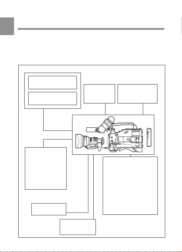
1-2 Example of System
1
Configuration
The diagram below shows a typical configuration of the camcorder for
ENG and EFP.
For more information about the fittings, connections, or use of additional
equipment and accessories, see Chapter 5 as well as the operation manuals for the
connected equipment.
Viewfinder-related equipment
Fog-proof filter
(Part No. 1-547-341-11)
BKW-401 Viewfinder
Rotation Bracket
Extension
board
MSDW-902 for SDI
output
MSDW-903 for
picture cache
MSDW-904 for
analog composite
input
Memory stick
BVF-VC10W
Color
viewfinder
RM-B150 Remote
Control Unit
a) For more information, see
Video monitor for
color image check
while shooting
Lens assembly
(Part No. A-8262-537-A)
Lens assembly
(Part No. A-8262-538-A)
Lens assembly
(Part No. A-8267-737-A)
Lens assembly
(3 × magnification)
(−2.4 D to +0.5 D)
(Part No. A-8314-798-A)
“Viewfinder and related
equipment” on page A-8.
a)
a)
a)
(−2.8 D to +2.0 D)
(−3.6 D to −0.8 D)
(−3.6 D to +0.4 D)
a)
Chapter 1 Overview1-6
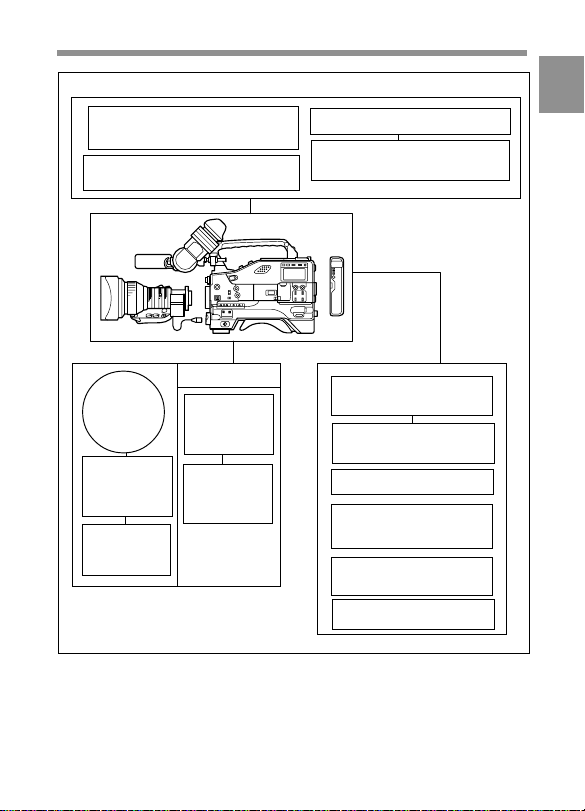
Camera adaptor
CA-701 for the input of the audio
channels 3/4 and the SDI output
CA-702/702P for CCZ (26-pin)
output/analog composite/SDI input
1
CA-755/755P Camera adaptor
CCU-550A/700A Camera
control unit
Power source
Battery
AC power
supply
AC-550/
550CE
AC Adaptor
AC-DN2B
AC Adaptor
a) 120 V AC or 220 to 240 V AC
a)
BC-L120
Battery
Charger
BP-L60A
Battery Pack
Audio signal source
External microphone
C-74, etc.
CAC-12 Microphone
Holder
Audio equipment
WRR-810A/860A/862A/
862B UHF Portable Tuner
WRR-855A/855B slotin UHF portable tuner
CCXA-53 audio cable
Chapter 1 Overview 1-7

1-3 Precautions
Use and Storage
1
Do not subject the camcorder to severe shocks
The internal mechanism may be damaged or the body warped.
After use
Always turn off the power.
Before storing the camcorder for a long period
Remove the battery pack.
Use and storage locations
Store in a level, ventilated place. Avoid using or storing the camcorder
in the following places.
• Places subject to temperature extremes
• Very damp places
• Places subject to severe vibration
• Near strong magnetic fields
• In direct sunlight or close to heaters for extended periods
To prevent electromagnetic interference from portable
communications devices
The use of portable telephones and other communications devices near
this unit can result in misoperations and interference with audio and
video signals.
It is recommended that the portable communications devices near this
unit be powered off.
Chapter 1 Overview1-8
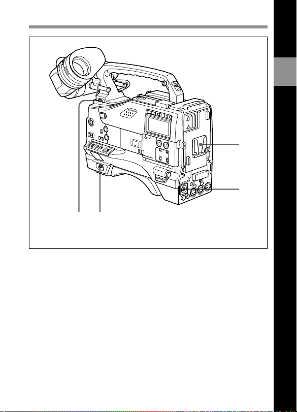
2-1 Power Supply
1
2
43
Power supply
1 Battery attachment
Attach a BP-L60A battery pack.
Furthermore, by attaching an AC-DN2B AC Adaptor, you can operate
the camcorder from AC power.
2
Locations and Functions of Parts and Controls
2 DC IN (external power input) connector (XLR type, 4-pin, male)
To operate the MSW-900/900P using an AC power supply, connect an
AC-550/550CE AC Adaptor with the DC output cable supplied with the
adaptor.
To use an external battery, connect its DC output cable to the DC IN
connector.
Chapter 2 Locations and Functions of Parts and Controls 2-1

3 POWER switch
This switch turns the main power supply on and off.
4 LIGHT switch
2
This switch selects the way in which a video light connected to the
LIGHT connector is switched on and off.
AUTO: The video light is automatically turned on, when starting
recording with the VTR starts, since a DC 12V signal is output from
the LIGHT connector during recording. When recording in Interval
Rec mode with the MSDW-903 (not supplied), the light is
automatically turned on before the start of recording since a DC 12V
signal can be automatically output before a frame picture is shot.
MANUAL: A DC 12V signal is always output from the LIGHT
connector. Whether the light is on or off is based on the position of
the ON/OFF switch of the light itself.
Chapter 2 Locations and Functions of Parts and Controls2-2

2-2 Accessory Attachments
12
89
Lens cable clamp
Accessory attachments
1 Shoulder strap posts
Attach the supplied shoulder strap to these posts.
2
3
4
5
6
7
2 Light shoe
Attach an optional accessory such as a video light to this shoe.
Chapter 2 Locations and Functions of Parts and Controls 2-3

3 LIGHT connector (2-pin, female)
Connect the cable of the Anton Bauer Ultralight System attached to the
light shoe. The system operates with lights powered by 12 V, with a
maximum power consumption of 50 W.
2
4 Lens mount (special bayonet mount)
Use this for mounting the lens.
5 Lens locking lever
After inserting the lens in the lens mount, rotate the lens mount ring with
this lever to lock the lens in position.
6 Lens mount cap
Remove this cap by pushing up on the lens locking lever. For protection
from dust, always insert this cap when no lens is mounted.
7 LENS connector (12-pin)
Fit the lens cable to this connector. Contact your Sony representative for
more information about the lens you are using.
8 Tripod mount
When using the unit on a tripod, attach the tripod adaptor.
9 Shoulder pad
You can move the shoulder pad forwards or backwards by loosening the
two screws. Do this to ensure the best balance when shooting with the
camcorder on your shoulder.
Chapter 2 Locations and Functions of Parts and Controls2-4
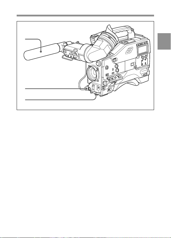
2-3 Audio Functions
1
2
3
Audio functions (1)
1 Microphone
This is a super-cardioid directional microphone with an external power
supply (+48 V) system.
2 MIC IN (microphone input) connector (XLR type, 5-pin, female)
The supplied microphone connects to this connector. By using an
extension cable (not supplied), you can connect a microphone other than
the supplied one as long as it is provided with an external power supply
system. The connector supplies power (+48 V) to the microphone.
3 MIC LEVEL knob
This knob adjusts the audio level of the microphone connected to the
MIC IN connector.
2
Chapter 2 Locations and Functions of Parts and Controls 2-5
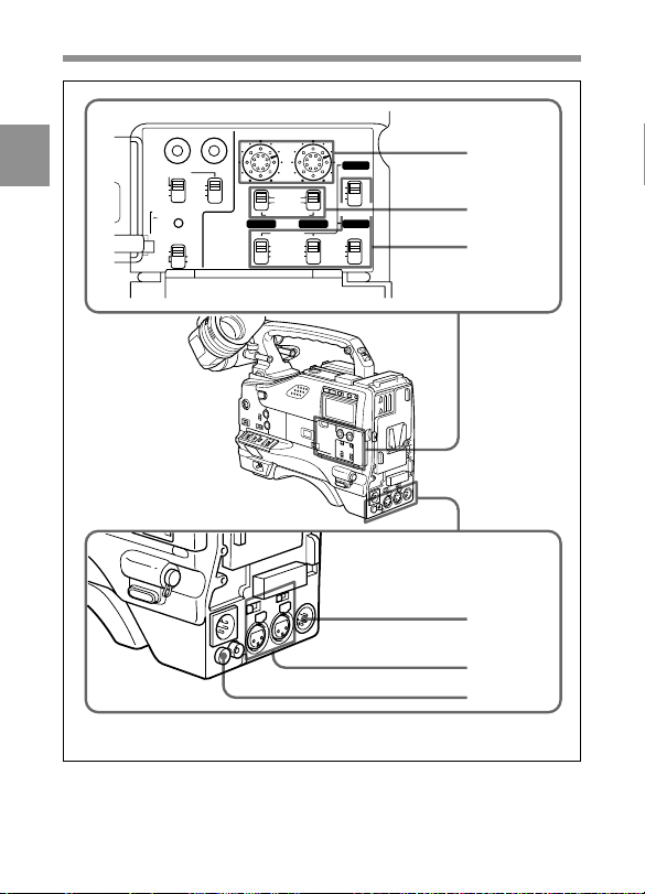
2
ADVANCE SHIFT LEVEL
PRESET
F-RUN
REGEN
SET
CLOCK
R-RUN
MEMORY STICK
OPEN
DATA DISPLAY
U-BIT
SHOT
TIME
NO
CH-1 CH-2 CH-4
100100
AUTO
MANUAL
AUDIO SELECT
AUDIO IN
FRONT
REAR
WIRELESS
CH-3
F
R
W
F
R
W
4
5
6
7
8
9
Audio functions (2)
Chapter 2 Locations and Functions of Parts and Controls2-6

4 LEVEL (CH-1/CH-2) (audio channel 1 and channel 2 recording
level) controls
These controls adjust the audio levels of channels 1 and 2 when the
AUDIO SELECT switches are set to MANUAL.
5 AUDIO SELECT (CH-1/CH-2) (audio channel-1 and channel-2
adjustment method select) switches
These switches select the audio level adjustment method for each of
audio channels 1 and 2.
AUTO: Select this setting for automatic adjustment.
MANUAL: Select this setting for manual adjustment.
6 AUDIO IN CH-1/CH-2 / CH-3/CH-4 (audio input select)
switches
AUDIO IN CH-1/CH-2 switches
These switches select the audio input signals to be recorded for audio
channels 1 and 2.
FRONT: The input signal source is the microphone connected to the
MIC IN connector.
REAR: The input signal source is the audio equipment connected to the
AUDIO IN CH-1/CH-2 connectors.
WIRELESS: The input signal source is a WRR-855A/855B UHF
Synthesized Tuner Unit (not supplied).
Note
Since the REAR XLR AUTO item is set to ON on the VTR MODE 1
page of the MAINTENANCE menu as the factory setting, the signal
input to the AUDIO IN CH-1 or CH-2 connector is automatically
selected as the signal to be recorded when the audio cable is connected to
either the AUDIO IN CH-1 or CH-2 connector, regardless of the AUDIO
IN CH-1/CH-2 switch settings (XLR connection automatic detection
function). To disable this function, set REAR XLR AUTO to OFF.
For detailed information on menu operation, see “4-6-2 Basic Use of the Menu”
on page 4-49.
2
Chapter 2 Locations and Functions of Parts and Controls 2-7

CH-3/CH-4 switches
These switches select the audio input signals to be recorded for audio
channels 3 and 4.
F (FRONT): The input signal source is the microphone connected to the
2
MIC IN connector.
R (REAR): The input signal source is the audio equipment connected to
the AUDIO IN CH-1/CH-2 connectors.
W (WIRELESS): The input signal source is a WRR-855A/855B UHF
Synthesized Tuner Unit (not supplied).
Note
These switches are not activated when you use the camcorder for the first
time after purchase because the camcorder has been set at the factory so
that the input signals to be recorded to audio channels 3 and 4 are the
same as the ones input to the AUDIO IN CH-1/CH-2 connectors.
To activate these switches, change the setting of the AUDIO CH3/4
MODE item from CH1/2 to SW on the VTR MODE 1 page of the
MAINTENANCE menu.
With a CA-701 (not supplied) connected to the camcorder, you can
record separate sounds on audio channels 3 and 4.
7 AUDIO OUT (audio output) connector (XLR type, 5-pin, male)
This connector outputs the audio signals recorded to audio channels 1
and 2 or audio channels 3 and 4.
The MONITOR CH-1/2 / CH-3/4 switches qs allow you to select the
audio signal to be monitored.
Using a CCXA-53 Audio Cable (not supplied), you can convert from a 5-pin
connection to two 3-pin connections.
Chapter 2 Locations and Functions of Parts and Controls2-8

8 AUDIO IN CH-1/CH-2 (audio channel 1 and channel 2 input)
connectors (XLR type, 3-pin, female) and LINE/MIC/+48 V ON
(line input/microphone input/external power supply +48V ON)
switches
These are audio input connectors for channels 1 and 2 to which you can
connect audio equipment or a microphone.
The LINE/MIC/+48V ON switches select the audio source of the audio
input signals connected to each of these connectors.
LINE: Line input audio equipment
MIC: Microphone with an internal power supply
+48V ON: Microphone with an external power supply system
9 DC OUT (DC power output) connector
This connector supplies power for a WRR-810A/860A/862A/862B UHF
Portable Tuner (not supplied). Do not connect any equipment other than
the UHF portable tuner.
2
Chapter 2 Locations and Functions of Parts and Controls 2-9
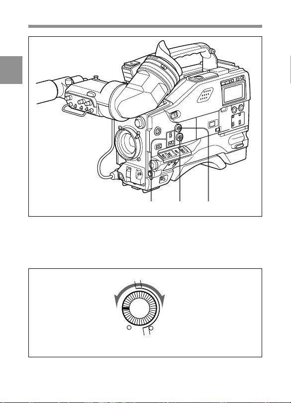
2
qs qa q;
Audio functions (3)
0 ALARM volume control
This control adjusts the speaker or earphone alarm volume. At the
minimum position, no sound can be heard.
ALARM
Minimum Maximum
ALARM volume control
Chapter 2 Locations and Functions of Parts and Controls2-10
qa MONITOR volume control
This control adjusts the speaker or earphone volume for sounds other
than the alarm sound. At the minimum position, no sound can be heard.
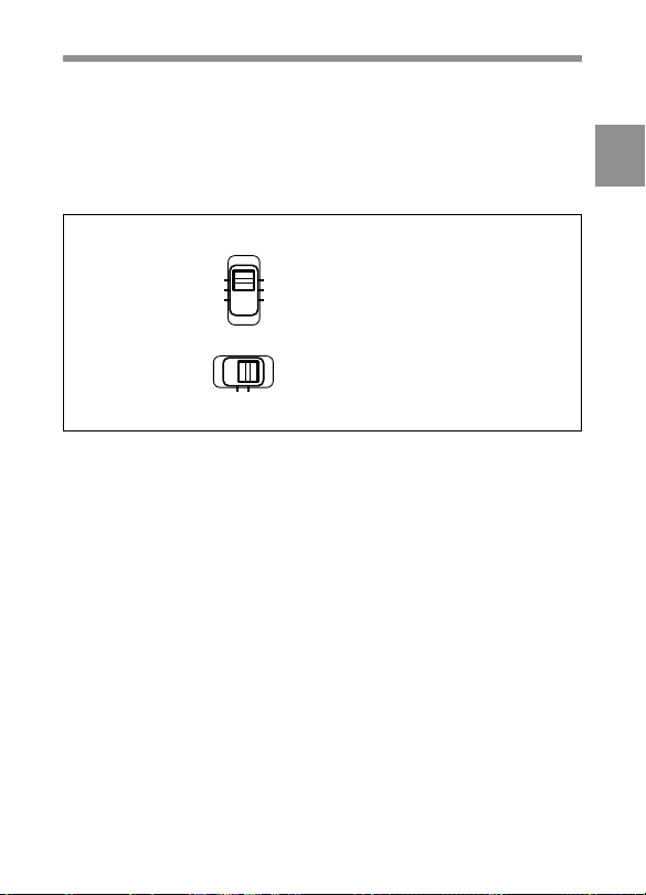
qs MONITOR (audio channel select) switch /CH-1/2 / CH-3/4 (audio
channel 1/2 / audio channel 3/4 select) switch
MONITOR
CH-1
MIX
CH-2
CH-1/2 CH-3/4
MONITOR switch and CH-1/2 / CH-3/4 switch
CH-3
MONITOR switch
MIX
CH-4
CH-1/2 / CH-3/4 switch
CH-1/2 / CH-3/4 switch
This switch decides the audio channel to be selected by the MONITOR
switch.
CH-1/2: Audio channels 1 and 2
CH-3/4: Audio channels 3 and 4
The following settings depend on the CH-1/2 / CH-3/4 switch setting:
• The signal output to the AUDIO OUT connector 7 is switched.
CH-1/2: Audio channels 1 and 2
CH-3/4: Audio channels 3 and 4
• The audio signal indicated by the audio level meter in the display
window is switched.
2
Chapter 2 Locations and Functions of Parts and Controls 2-11

MONITOR switch
This switch selects the audio output to the speaker or earphone.
CH-1/2 CH-3/4 MONITOR switch Audio output
2
position position
CH-1/2 CH-1 Audio channel 1
MIX Mix sound of channels 1 and 2
CH-2 Audio channel 2
CH-3/4 CH-3 Audio channel 3
MIX Mix sound of channels 3 and 4
CH-4 Audio channel 4
Chapter 2 Locations and Functions of Parts and Controls2-12

qf
Audio functions (4)
qd
2
qd Built-in speaker
During recording, the speaker can be used for monitoring the E-E
1)
sound, and during playback for monitoring playback sound. The speaker
also sounds alarms to reinforce visual warnings.
If an earphone is plugged into to the EARPHONE jack, the speaker
sound is automatically cut off.
See “6-3 Operation Warnings” on page 6-14 for information about alarms.
....................................................................................................................................
1) E-E sound (Electric-to-Electric sound)
The term E-E sound refers to an audio signal that has passed though the
amplifier, but has not been recorded on the tape. In other words, you can directly
monitor the recording input signal, as opposed to the simultaneous playback
(output) signal.
Chapter 2 Locations and Functions of Parts and Controls 2-13

qf EARPHONE jacks (minijack)
You can monitor the E-E sound during recording and playback sound
during playback. Plugging an earphone into the jack automatically cuts
off the built-in speaker, and you hear the alarms about the camcorder’s
2
operation and status through the earphone.
The signals output from these jacks are the same. You can connect two
earphones to these jacks at the same time.
Chapter 2 Locations and Functions of Parts and Controls2-14
 Loading...