

Sony MSU-750 Maintenance Manual

MASTER SETUP UNIT
MSU-750
MAINTENANCE MANUAL Part 2
1st Edition
Serial No. 15001 and Higher
MSU-750 MMP2
! W ARNING
This manual is intended for qualified service personnel only.
To reduce the risk of electric shock, fire or injury, do not perform any servicing other than that
contained in the operating instructions unless you are qualified to do so. Refer all servicing to
qualified service personnel.
! W ARNUNG
Die Anleitung ist nur für qualifiziertes Fachpersonal bestimmt.
Alle Wartungsarbeiten dürfen nur von qualifiziertem Fachpersonal ausgeführt werden. Um die
Gefahr eines elektrischen Schlages, Feuergefahr und Verletzungen zu vermeiden, sind bei
Wartungsarbeiten strikt die Angaben in der Anleitung zu befolgen. Andere als die angegeben
Wartungsarbeiten dürfen nur von Personen ausgeführt werden, die eine spezielle Befähigung
dazu besitzen.
! AVERTISSEMENT
Ce manual est destiné uniquement aux personnes compétentes en charge de l’entretien. Afin
de réduire les risques de décharge électrique, d’incendie ou de blessure n’effectuer que les
réparations indiquées dans le mode d’emploi à moins d’être qualifié pour en effectuer d’autres.
Pour toute réparation faire appel à une personne compétente uniquement.
MSU-750 MMP2
CAUTION
Danger of explosion if battery is incorrectly
replaced.
Replace only with the same or equivalent type
recommended by the manufacturer.
Dispose of used batteries according to the
manufacturer’s instructions.
Vorsicht!
Explosionsgefahr bei unsachgemäßem
Austausch der Batterie.
Ersatz nur durch denselben oder einen vom
Hersteller empfohlenen ähnlichen Typ.
Entsorgung gebrauchter Batterien nach Angaben
des Herstellers.
ATTENTION
Il y a danger d’explosion s’il y a remplacement
incorrect de la batterie.
Remplacer uniquement avec une batterie du
même type ou d’un type équivalent recommandé
par le constructeur.
Mettre au rebut les batteries usagées
conformément aux instructions du fabricant.
ADVARSEL!
Lithiumbatteri-Eksplosionsfare ved fejlagtig
håndtering.
Udskiftning må kun ske med batteri
af samme fabrikat og type.
Levér det brugte batteri tilbage til leverandøren.


1 (E)
MSU-750 MMP2
Table of Contents
Manual Structure
Purpose of this manual ........................................................................................ 3 (E)
Related manuals................................................................................................... 3 (E)
Contents ............................................................................................................... 4 (E)
1. Service Overview
1-1. Self-Diagnosis .......................................................................................1-1 (E)
1-2. PROM ...................................................................................................1-3 (E)
1-2-1. PROM Version Check..........................................................1-3 (E)
1-2-2. Notes on PROM Replacement .............................................1-3 (E)
1-3. Description on Flexible Card Wire .......................................................1-4 (E)
1-3-1. Disconnecting/Connecting of Flexible Card Wire ...............1-4 (E)
1-4. Replacing Switching Regulator.............................................................1-5 (E)
1-5. Replacing Fuse ......................................................................................1-6 (E)
1-6. Replacing LED-334/335 Boards ...........................................................1-7 (E)
1-7. Replacing EL Display .........................................................................1-10 (E)
1-8. Note on Servicing................................................................................1-11 (E)
2. Spare Parts
2-1. Notes on Repair Parts.................................................................................. 2-1
2-2. Exploded Views .......................................................................................... 2-2
2-3. Electrical Parts List ..................................................................................... 2-8
2-4. Power Cords List....................................................................................... 2-19
3. Semiconductor Pin Assignments
4. Block Diagrams
CPU-286......................................................................................................4-4
SW-6 ...........................................................................................................4-6
Overall Block .............................................................................................. 4-2

2 (E)
MSU-750 MMP2
5. Schematic Diagrams
CPU-286...................................................................................................... 5-2
SW-6 ......................................................................................................... 5-15
Frame Wiring ............................................................................................5-20
6. Board Layouts
CN-1803 ......................................................................................................6-1
CN-1807 ......................................................................................................6-1
CPU-286...................................................................................................... 6-2
LED-334...................................................................................................... 6-4
LED-335...................................................................................................... 6-5
LED-336...................................................................................................... 6-5
SW-6 ........................................................................................................... 6-6

3 (E)
MSU-750 MMP2
Manual Structure
Purpose of this manual
This manual is the maintenance manual part 2 of Master Setup Unit MSU-750.
This manual describes the information items on maintenance, and items that
premise the service based on the components parts such as service overview, parts
list, semiconductor pin assignments, block diagrams, schematic diagrams and board
layouts, assuming use of system and service engineers.
Related manuals
Besides this “maintenance manual part 2”, the following manuals are available for
this unit.
..
..
. Operation Manual (Supplied with the MSU-750)
This manual is necessary for application and operation of this unit.
..
..
. Maintenance Manual Part 1 (Supplied with the MSU-750)
This manual is intended for use by trained system and service engineers, and
provides the installation and maintenance information that is necessary at the time
of primary service.
..
..
. System Manual (Available on request)
This manual is necessary for connection and operation of video camera and other
peripheral equipment.
If this manual is required, please contact your local Sony Sales Office/Service
Center.
..
..
. “Semiconductor Pin Assignments” CD-ROM (Available on request)
This “Semiconductor Pin Assignments” CD-ROM allows you to search for
semiconductors used in Broadcasting & Professional Systems Company
equipment.
Semiconductors that cannot be searched for on this CD-ROM are listed in the
maintenance manual for the corresponding unit. The maintenance manual contains
a complete list of all semiconductors and their ID Nos., and thus should be used
together with the CD-ROM.
Part number: 9-968-546-XX

4 (E)
MSU-750 MMP2
Contents
The following are summaries of all the sections for understanding the contents of
this manual.
Section 1 Service Overview
Describes note on servicing, parts replacement procedures, PROM and self-diagnosis.
Section 2 Spare Parts
Describes parts list and exploded views used in the unit.
Section 3 Semiconductor Pin Assignments
Describes function diagrams and pin names of semiconductor used in the unit.
Use the separate “Semiconductor Pin Assignments” CD-ROM together with this
manual.
Section 4 Block Diagrams
Describes overall block diagram and the block diagrams for every circuit board.
Section 5 Schematic Diagrams
Describes schematic diagrams for every circuit board.
Section 6 Board Layouts
Describes board layouts for every circuit board.

1-1 (E)
MSU-750 MMP2
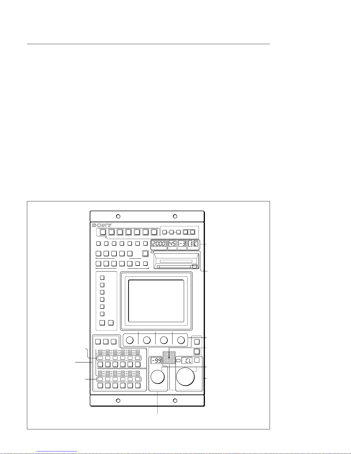
1-1. Self-Diagnosis
Operation of the switches, LED indicators, and rotary encoders on the control panel can be checked by
the self-diagnosis mode of the unit.
Preparations
1. Press [PANEL|ACTIVE], [PARA], and SCENE FILES [1] switches at the same time.
Operation check
Switch with LED
When the desired switch is pressed, the LED inside the switch lights up. And when the buzzer ON/OFF
switch S6 on the CPU-286 board is in ON position, the buzzer beeps at the same time. To turn off the
LED, press switch again. (Avoid lighting all the switches simultaneously for a relatively long period of
time.)
Indicator
1. Camera number/Tally display block
Make sure that a red and green cross indication moves from the right to left.
2. Make sure that the CARD ACCESS indicator blinks in sequence of red, green then orange.
3. Make sure that the MULTI, TALLY, and PANEL ACTIVE indicators of the camera selector block
blink in sequence of red, green then off.
4. Make sure that the EXT indicator of the IRIS adjusting block blinks.
5. Make sure that the 7-segment LEDs of ECS/SHUTTER, GAMMA, MASTER GAIN, FILTER
display blocks and MASTER BLACK and IRIS adjusting blocks light up in the following order.
Rotary encoder
When the desired rotary encoder has been turned, the ID number corresponded with the rotary encoder
will be displayed on the IRIS adjusting block, and the control value is displayed on the MASTER
BLACK adjusting block.
Character display block
The ROM version flows from the right to left in this block as a slide-show.
Section 1
Service Overview
Red
Green
1
4
8
7
2
3
6
5
1-2 (E)
MSU-750 MMP2
321
0
4
5
Rotary encoder
Rotary encoder
IRIS adjusting block
MASTER BLACK adjusting block
CHARACTER display block
CHARACTER display block
Camera selector block
Camera number/
Tally display block
AUTO SETUP
MODE
MASTER SETUP UNIT
IC MEMORY CARD
12345
RGB
SEQ ENC
WF PIX
AUTO
HUE
LEVEL
ALL CLOSE
STANDARD
CAM PW
MULTI
CARD
CONFIG
MAINTENANCE
FILE
PAINT
0 70 80 91 01 11 2
0 10 20 30 40 50 6
PANEL
ACTIVE
PARA
EXPAND
FUNCTION
MULTI
TALLY
MULTI
TALLY
VF PW TEST BARS
5600K
AUTO
KNEE
SKIN
DETAIL
CHARACTER
START/
BREAK
WHITE BLACK
ECS/SHUTTER
ACCESS
STORE
SCENE FILES
MONITOR
GAMMA
MASTER
GAIN
ND
FILTER
CC
MASTER BLACK IRIS
IRIS/MB
ACTIVE
CALL
AUTO
EXT
ECS/SHUTTER display block
GAMMA display block
MASTER GAIN display block
FILTER display block
CARD ACCESS indicator
1-1. Self-Diagnosis
Finishing the self-diagnosis mode
1. Press [PANEL|ACTIVE], [PARA], and SCENE FILES [1] switches at the same time.

1-3 (E)
MSU-750 MMP2
1-2. PROM
Program names are shown in the suffix of original name of the PROMs. When the version of program
changes, the suffix of program name will be changed.
Be sure not to use the unprogrammed PROMs. Since all the PROMs are mounted on the board through
the IC socket, be very careful when removing the PROMs.
. IC5/CPU-286 board
. IC6/CPU-286 board
1-2-1. PROM Version Check
n
The version indication can be displayed in “Engineer Mode” and above.
(Refer to the Operation Manual.)
Select “MSU” in the menu (configuration menu) on the EL display, then select “Information” successively. The version of PROMs will be displayed.
1-2-2. Notes on PROM Replacement
When replacing PROM (IC5 or IC6) on the CPU-286 board, be sure to replace both IC5 and IC6 at the
same time. When mounting the PROMs, be sure to insert MSU7x0AL (LOW) in IC5 and MSU7x0AH
(HIGH) in IC6.
If you are confused between IC5 and IC6, this unit does not operate normally.
1-2. PROM
1-4 (E)
MSU-750 MMP2
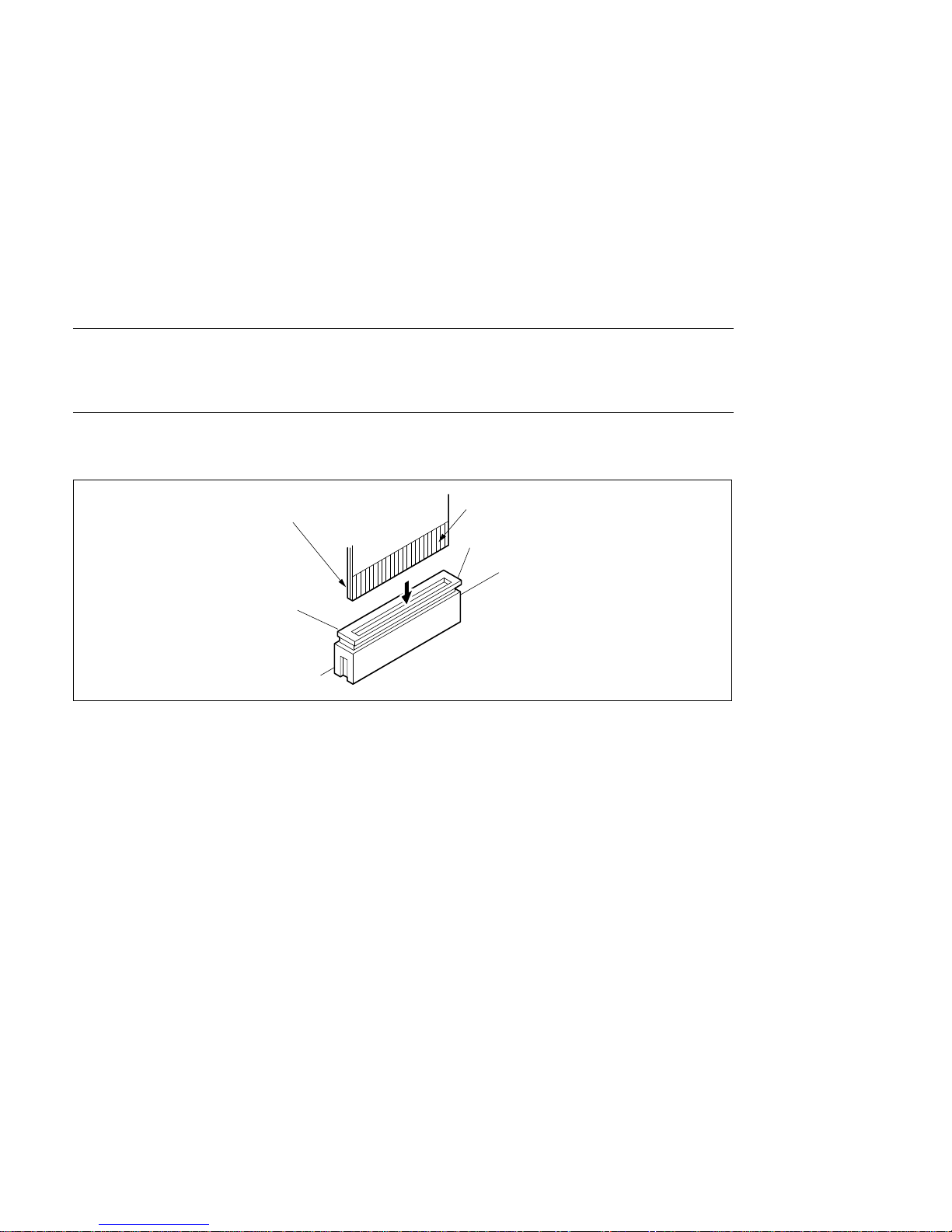
1-3. Description on Flexible Card Wire
The flexible card wires are used between the CPU board and CN board. Take care not to brake the
flexible card wires. This shortens the life.
1-3-1. Disconnecting/Connecting of Flexible Card Wire
Straight Type
Disconnecting
Pull up the * marked portions of the connector, and pull out the flexible card wire from the connector.
Connecting
Insert the flexible card wire as far as it will go, and push down the * marked portions of the connector.
m
1. Be careful not to insert the flexible card wire obliquely.
2. Check that the conductive surface of the flexible card wire is not soiled with dust.
1-3. Description on Flexible Card Wire
Flexible card wire
*
*
Conducting
surface
1-5 (E)
MSU-750 MMP2
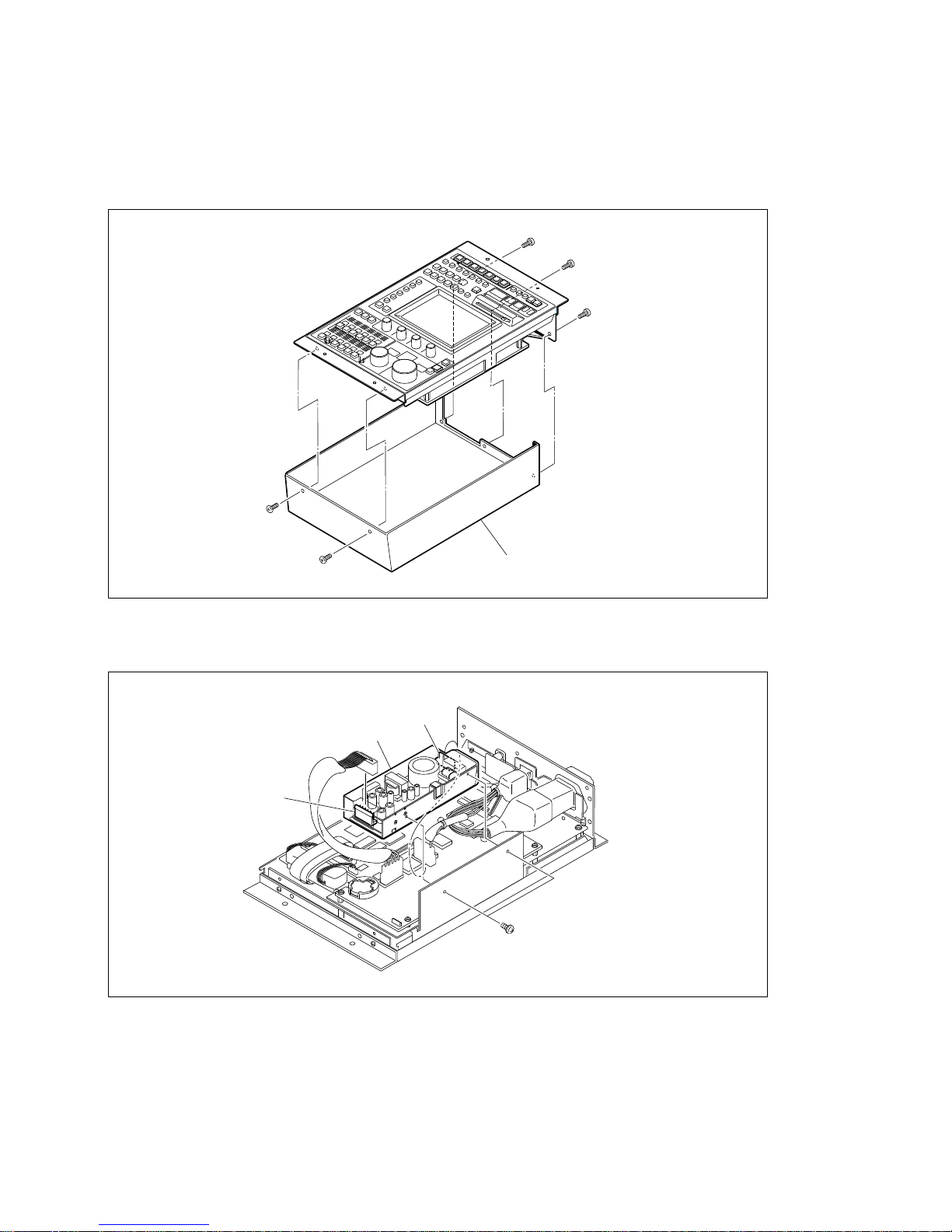
1-4. Replacing Switching Regulator
1. Turn off the power of the unit and disconnect the power cord from the unit.
2. Remove the five screws and remove the bottom chassis.
3. Disconnect connectors CN1 and CN2 from the switching regulator.
4. Remove the two screws and remove the switching regulator.
5. Assemble the unit in the reverse procedure of steps 2 to 4.
B3 x 6
B3 x 6
B3 x 6
B3 x 6
B3 x 6
Bottom chassis
PS3 x 5
Switching regulator
CN1
CN2
1-4. Replacing Switching Regulator

1-6 (E)
MSU-750 MMP2
1-5. Replacing Fuse
w
To reduce the risk of electric shock or fire, do not replace any fuse other than the specified fuse in order
to continue safety.
Be sure to replace a defective fuse with the following specified one:
Fuse, Glass Tube 3 A, 250 V: ! 1-532-827-11
1. Remove the bottom chassis. (Refer to steps 1 and 2 of Section “1-4. Replacing Switching Regulator.”)
2. Lift up one end of shield cover and remove the fuse.
3. Insert a new fuse in the reverse procedure of steps 1 and 2.
Shield cover
Fuse
Switching regulator
1-5. Replacing Fuse
1-7 (E)
MSU-750 MMP2
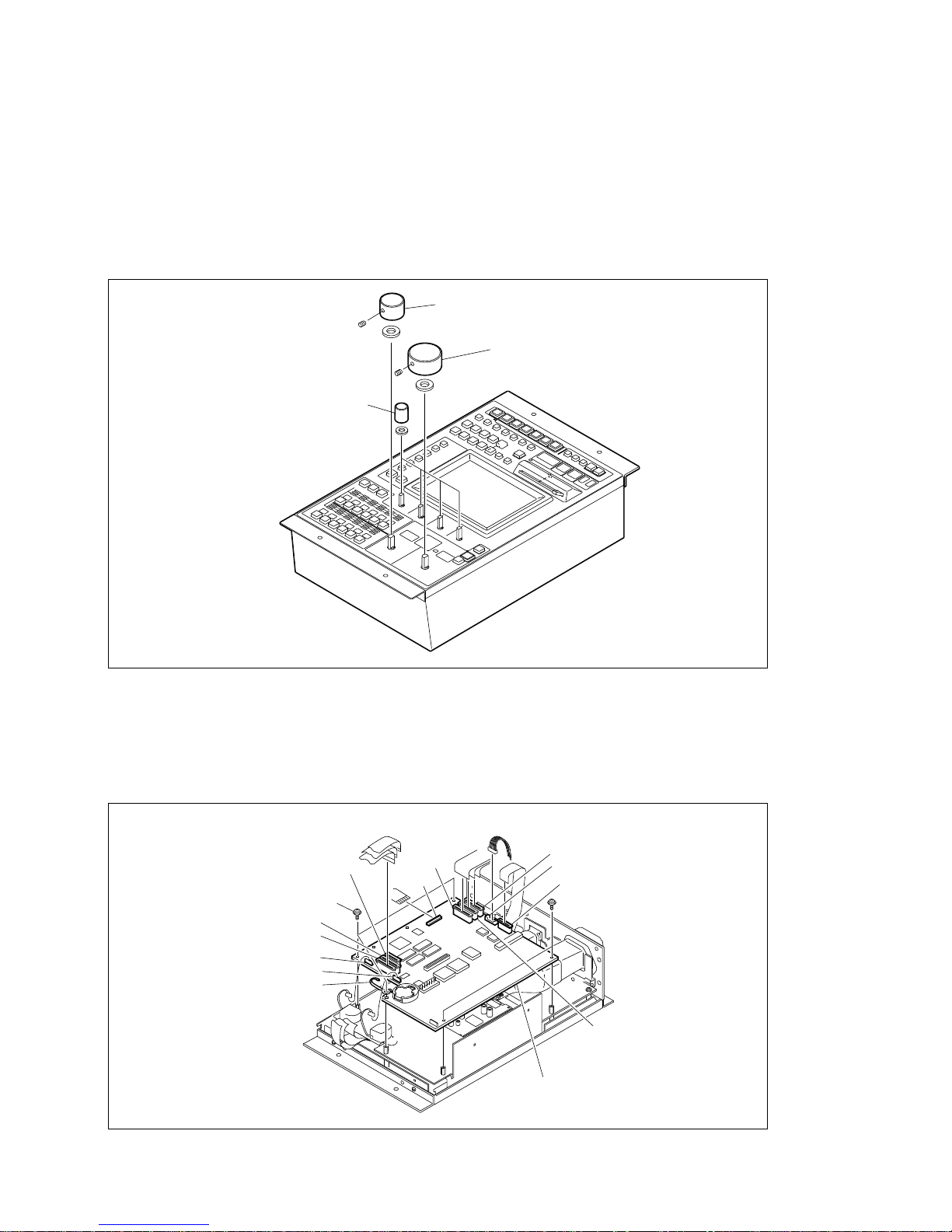
1-6. Replacing LED-334/335 Boards
n
Refer to section 1-3-1 when installing/removing the flexible card wire.
1. Loosen the setscrews and remove the two knobs (IRIS and MASTER BLACK).
2. Remove the four knobs of the menu operation block.
3. Remove the bottom chassis and switching regulator. (Refer to Section “1-4. Replacing Switching
Regulator.”)
4. Disconnect the following eleven connectors from the CPU-286 board. (CN102, CN201, CN202,
CN203, CN302, CN401, CN402, CN403, CN404, CN405 and CN406)
5. Remove the five screws and remove the CPU-286 board.
Washer (W6)
Washer (W6)
Washers (W4)
Setscrew
M4 x 6
Setscrew
M4 x 6
Knobs (menu operation block)
MASTER BLACK knob
IRIS knob
CPU-286 board
PWH3 x 6
PWH3 x 6
CN401
CN202
CN102
CN302
CN203
CN406
CN201
CN402
Wire clamp
CN403
CN404
CN405
1-6. Replacing LED-334/335 Boards
1-8 (E)
MSU-750 MMP2
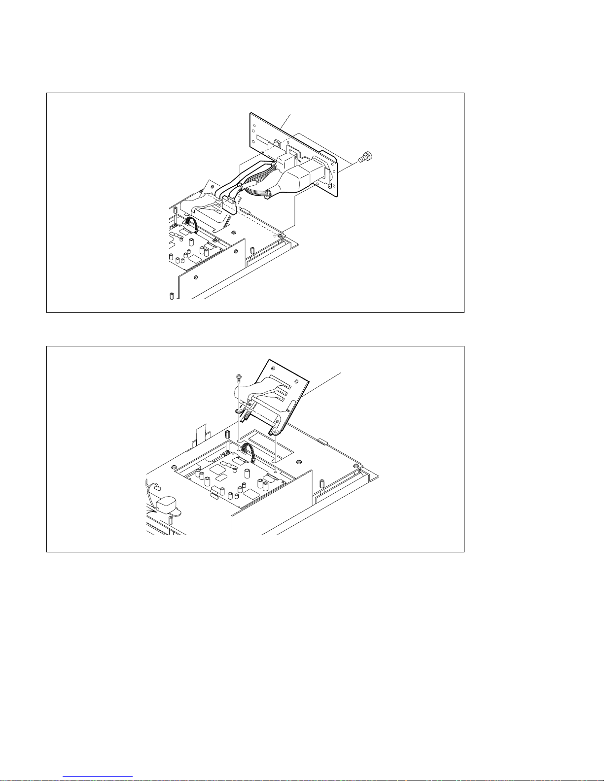
6. Remove the two screws and remove the connector panel.
7. Remove the two screws and remove the CN-1807 board.
Connector panel
PS3 x 5
PS3 x 8
CN-1807 board
1-6. Replacing LED-334/335 Boards

1-9 (E)
MSU-750 MMP2
8. Remove the five screws and spacers.
9. While pushing the SW-6 board in the arrow direction, lift up the SW-6 board and remove it by
stepping aside from the projection section of chassis.
10. Remove the LED-334 board from connectors CN24 and CN26 of the SW-6 board.
11. Desolder the soldering from connectors CN2 and CN3 on the LED-334 board and remove the LED335 board.
12. To install the LED-334 and LED-335 boards, perform reverse procedures of steps 1 to 11.
PWH3 x 6
PWH3 x 6
PWH3 x 6
SW-6 board
Spacer
Spacer
Spacer
Projection section of chassis
CN26
CN3
CN24
LED-334 board
LED-335 board
SW-6 board
CN2
1-6. Replacing LED-334/335 Boards
1-10 (E)
MSU-750 MMP2
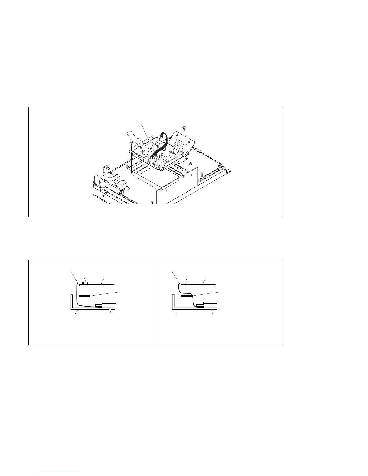
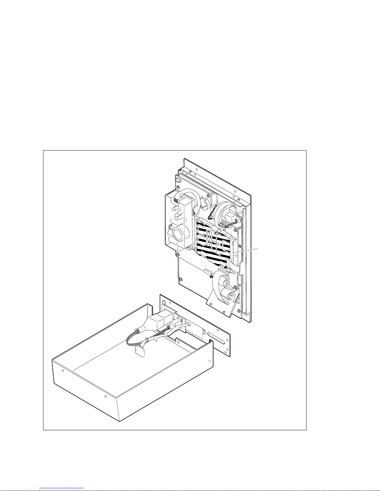
1-7. Replacing EL Display
1. Remove the bottom chassis and switching regulator. (Refer to Section “1-4. Replacing Switching
Regulator.”)
2. Remove the CPU-286 board. (Refer to Steps 4 and 5 of Section “1-6. Replacing LED-334/335
Boards.”)
3. Remove the four screws and remove the EL display.
4. To install the EL display, perform reverse procedures of steps 1 to 3.
n
When installing the EL display, the flexible card wire must be passed under the SW-6 board and then
connected to the connector CN406 on the CPU-286 board.
PSW3 x 10
PSW3 x 10
EL display
1-7. Replacing EL Display
EL display
CPU-286
board
Flexible card wire Flexible card wire
CN406
SW-6
board
Chassis
OK
NG
EL display
CPU-286
board
CN406
SW-6
board
Chassis
1-11 (E)
MSU-750 MMP2
1-8. Note on Servicing
1. w
The EL display block carries high voltage. Do not touch it with bare hands, as this is extremely
dangerous. Take extreme care.
The voltage of 200 V AC from the DC/AC inverter is applied to the EL display block.
When repairing or checking the unit while turning on the power, take care of an electric shock.
2. One switching regulator is mounted on the unit. Take care of an electric shock on the primary side of
power circuit in the switching regulator.
3. Running the power supply unit under no load may cause power source trouble. Never check the
power supply unit independently.
EL display block
1-8. Note on Servicing


2-1
MSU-750 MMP2
2-1. Notes on Repair Parts
1. Safety Related Components Warning
w
Components marked ! are critical to safe operation.
Therefore, specified parts should be used in the case of
replacement.
2. Standardization of Parts
Some repair parts supplied by Sony differ from those
used for the unit. These are because of parts commonality and improvement.
Parts list has the present standardized repair parts.
3. Stock of Parts
Parts marked with “o” at SP (Supply Code) column of
the spare parts list may not be stocked. Therefore, the
delivery date will be delayed.
Section 2
Spare Parts
2-2
MSU-750 MMP2
B3 x 6
PWH3 x 6
PS3 x 5
PS3 x 5
B3 x 6
B3 x 6
B3 x 6
PWH3 x 6
PSW3 x 10
PSW3 x 10
PWH3 x 6
P2.6 x 4
W4
(POLY)
W6
(POLY)
W6
(POLY)
19
9
10
16
9
3
12
2
16
20
4
6
1
13
8
11
17
18
19
7
5
15
14
12
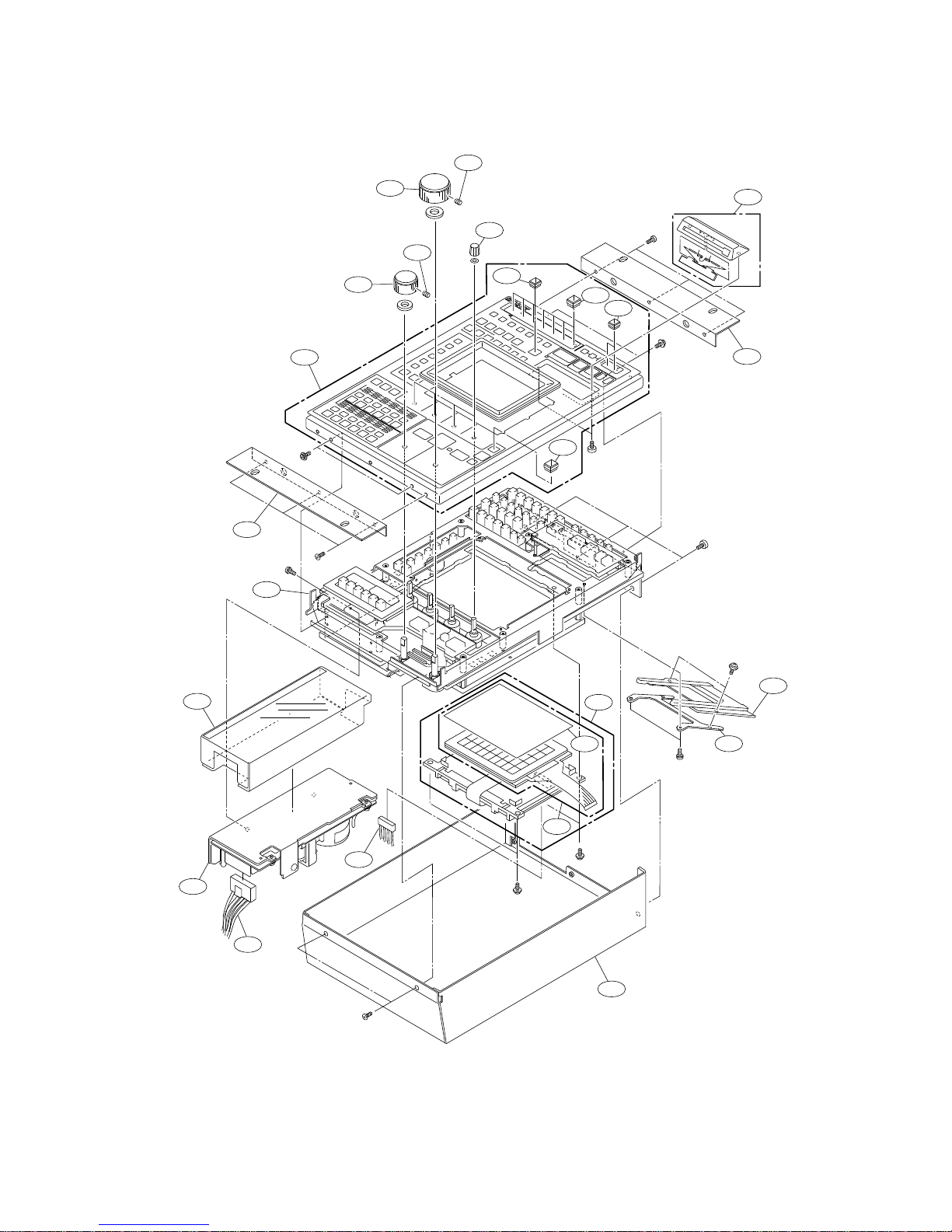
2-2. Exploded Views

2-3
MSU-750 MMP2
No. Part No. SP Description
1 A-8314-206-A o EL ASSY
2 A-8322-641-A o PANEL ASSY, OPERATION
3 A-8322-644-A o GUARD ASSY, IC CARD
4 A-8322-645-A o MOUNTED CIRCUIT BOARD, CN-1807
5 ! 1-468-411-11 s SWITCHING REGULATOR
6 1-762-125-11 s SWITCH,TOUCH PANEL (WITH FILM)
7 1-959-870-11 o HARNESS (DC)
8 1-959-871-11 o HARNESS (EL)
9 2-141-006-01 o GUARD, SWITCH
10 3-622-201-02 o KNOB
11 3-622-380-01 o BRACKET,IC CARD
12 3-622-386-01 o BRACKET,ANGLE
13 3-622-387-01 o CHASSIS,BOTTOM
14 3-622-388-01 o CHASSIS,MAIN
15 3-622-393-01 o SHEET,INSULATING(AC)
16 3-681-389-01 o SWITCH GUARD
17 3-681-390-02 o KNOB IRIS
18 3-681-391-02 o KNOB M.BLK
19 3-701-511-00 s SET-SCREW,HEXGON 4X6 (WP) ST
20 3-708-928-01 s FILM, COVER (PLA)
Main Parts Block

2-4
MSU-750 MMP2
No. Part No. SP Description
101 3-708-877-01 s CAP (PC)
102 3-708-877-61 s CAP (PC)
103 3-708-877-71 s CAP (PC)
104 3-708-877-81 s CAP (PC)
105 3-708-895-01 s CAP (PC)
106 3-708-930-01 s CAP (PC)
107 3-708-930-11 s CAP (PC)
108 3-708-930-21 s CAP (PC)
109 3-708-930-31 s CAP (PC)
110 3-708-930-41 s CAP (PC)
111 3-708-932-11 s CAP (PC)
112 3-708-932-21 s CAP (PC)
113 3-708-933-11 s CAP (PC)
114 3-708-934-01 s CAP (PC)
115 3-708-935-01 s CAP (PC)
116 3-708-938-01 s CAP (PC)
117 3-708-940-01 s CAP (PC)
Switch Caps’
SEQ ENC
CALL
1
07 08 09 10 11 12
01 02 03 04 05 06
RGB
2 3 4 5
SEQ ENC
1
RGB
2 3 4 5
105
114101114115
117
105
101
115
114
115
101
110108106
112104102
107 109
111103
116
105
116
105
113
114
101
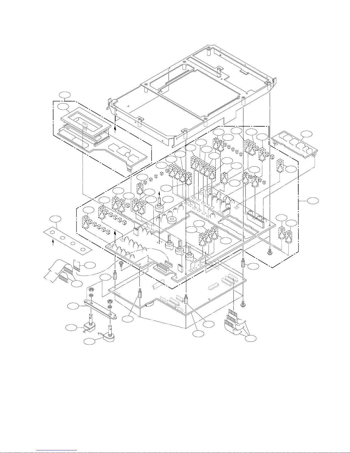
No. Part No. SP Description
201 A-8322-649-A o MOUNTED CIRCUIT BOARD, LED-335
202 A-8322-653-A o MOUNTED CIRCUIT BOARD, SW-6
203 A-8322-654-A o MOUNTED CIRCUIT BOARD, CPU-286
204 A-8322-655-A o MOUNTED CIRCUIT BOARD, LED-334
205 1-418-485-11 s ENCODER, ROTALY
206 1-466-955-21 s ENCODER, ROTARY (SWITCH)
207 1-574-144-11 s WIRE, FLAT TYPE (12 CORE)
208 1-574-161-11 s CABLE,FLAT (1MM PITCH) 25P
209 1-674-348-11 o PRINTED WIRING BOARD, LED-336
210 1-692-994-11 s SWITCH, TACTILE (ILLUMINATED)
211 1-692-994-71 s SWITCH, TACTILE (ILLUMINATED)
212 1-692-994-81 s SWITCH, TACTILE (ILLUMINATED)
213 1-692-994-91 s SWITCH, TACTILE (ILLUMINATED)
214 1-762-042-11 s SWITCH, TACTILE (ILLUMINATED)
215 1-762-129-11 s SWITCH, TACTILE (ILLUMINATED)
216 1-762-129-21 s SWITCH, TACTILE (ILLUMINATED)
217 1-762-129-31 s SWITCH, TACTILE (ILLUMINATED)
218 1-762-129-41 s SWITCH, TACTILE (ILLUMINATED)
219 1-762-129-51 s SWITCH, TACTILE (ILLUMINATED)
220 1-762-131-21 s SWITCH, TACTILE (ILLUMINATED)
221 1-762-131-31 s SWITCH, TACTILE (ILLUMINATED)
222 1-762-132-21 s SWITCH, TACTILE (ILLUMINATED)
223 1-762-133-11 s SWITCH, TACTILE (ILLUMINATED)
2-5
MSU-750 MMP2
Board Block
PWH3 x 6
PWH3 x 6
*1
*1
*2
PWH3 x 6
*2
204
201
205
221
224
210
223
210
210
224
214
211
226
214
223
202
214
220
223
210
222
209
224
223
210
215
216
217
218
219
227
208
227
206
206
228
229
227
208
207
214
225
225
213
212
203
227
No. Part No. SP Description
224 1-762-134-11 s SWITCH, TACTILE (ILLUMINATED)
225 1-762-137-11 s SWITCH, TACTILE (ILLUMINATED)
226 1-762-139-11 s SWITCH, TACTILE (ILLUMINATED)
227 3-608-402-01 o SPACER
228 3-622-379-01 o BRACKET,ENC
229 3-622-396-01 o SHEET,ENC
2-6
MSU-750 MMP2
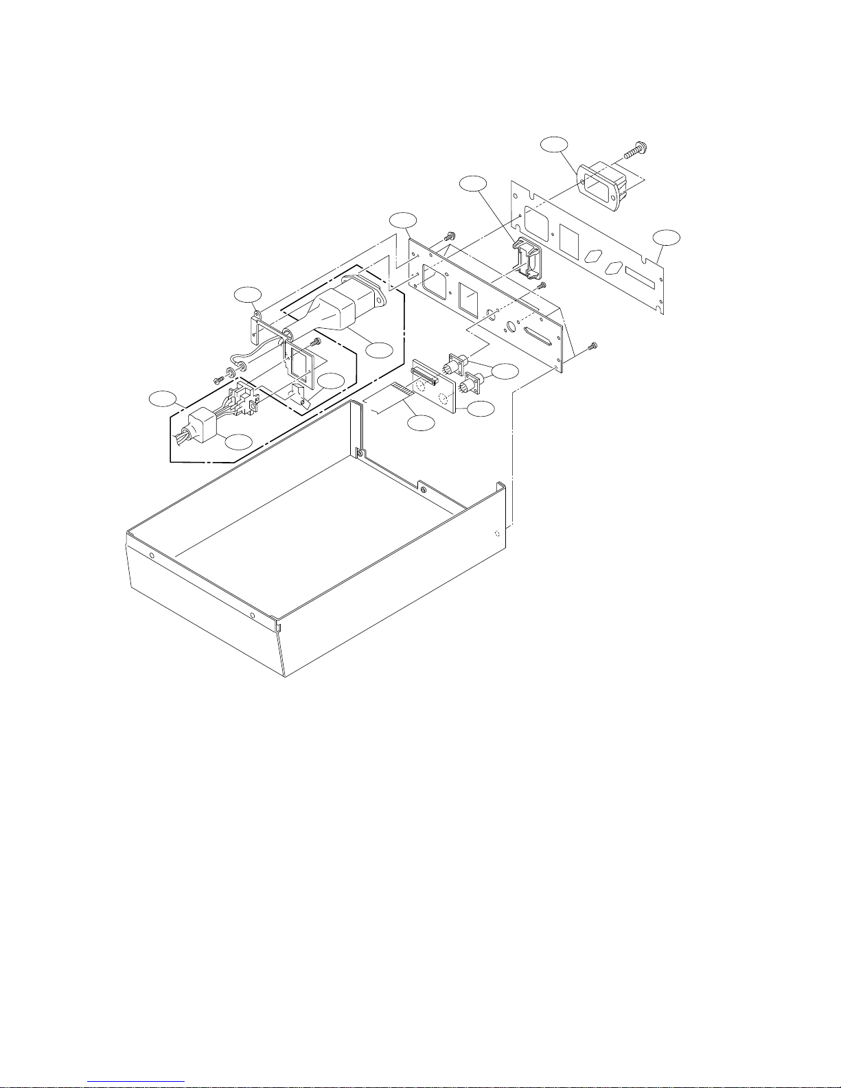
Rear Panel Block
No. Part No. SP Description
301 1-574-144-11 s WIRE, FLAT TYPE (12 CORE)
302 1-674-347-11 o PRINTED WIRING BOARD, CN-1803
303 1-766-696-11 o CONNECTOR, ROUND TYPE 8P
304 ! 1-959-872-11 o HARNESS (PS)
305 2-990-241-02 s HOLDER (A), PLUG
306 3-622-383-01 o PANEL,CONNECTOR
307 3-622-384-01 o BRACKET,AC
308 3-622-385-01 o SHEET,CONNETOR PANEL
309 3-681-054-01 o POWER SW GUARD
310 3-688-814-01 s CAP,SWITCH
311 4-381-806-01 o COVER,SWITCH
312 4-605-511-02 o COVER, INLET, 3P
P2.6 x 4
B3 x 6
PWH3 x 12
PSW3 x 6
305
312
304
308
309
306
303
302
301
PS3 x 5
PS4 x 5
W4
(MIDDLE)
307
311
310
 Loading...