

Page 1

Marine Pack
3-090-357-12 (1)
Operating Instructions
Mode d’emploi
Manual de instrucciones
使用說明書
사용설명서
GB
FR
ES
CT
KR
MPK-DVF6
©2004 Sony Corporation
Page 2

For the customers in U.S.A.
CAUTION
You are cautioned that any changes or modifications not expressly approved in this
manual could void your authority to operate this equipment.
NOTE:
This equipment has been tested and found to comply with the limits for a Class B
digital device, pursuant to Part 15 of the FCC Rules. These limits are designed to
provide reasonable protection against harmful interference in a residential installation.
This equipment generates, uses, and can radiate radio frequency energy and, if not
installed and used in accordance with the instructions, may cause harmful interference
to radio communications. However, there is no guarantee that interference will not
occur in a particular installation. If this equipment does cause harmful interference to
radio or television reception, which can be determined by turning the equipment off
and on, the user is encouraged to try to correct the interference by one or more of the
following measures:
– Reorient or relocate the receiving antenna.
– Increase the separation between the equipment and receiver.
– Connect the equipment into an outlet on a circuit different from that to which the
receiver is connected.
– Consult the dealer or an experienced radio/TV technician for help.
2-GB
Page 3

Table of contents
Features and Precautions ........................... 3
Supplied Accessories................................... 4
Preparations ................................................. 5
Preparing your camcorder................... 5
Preparing the marine pack (installing
the battery) ........................................... 12
Installing the camcorder to the marine
pack ....................................................... 14
Underwater recording .............................. 20
Recording .................................................... 22
Attaching the supplied accessories
............................................................... 23
Using the underwater video light
(optional) .............................................. 24
Removing the camcorder ......................... 25
Note on the O-ring .................................... 29
Caution on handling ................................. 33
Identifying parts and controls ................. 34
Specifications.............................................. 35
Features and Precautions
• The MPK-DVF6 can be used with the Sony Handycam Vision™ camcorder DCRHC40/HC40E/HC30/HC30E/HC20/HC20E/HC18E/HC16E/PC109/PC109E/
PC108/PC108E/PC107E/PC106E/TRV900/TRV900E/TRV890E/TRV118E/
TRV116E/TRV50/TRV50E/TRV40/TRV40E/TRV30/TRV30E/TRV27/TRV27E/
TRV25/TRV25E/TRV24E/TRV20/TRV20E/TRV18/TRV18E/TRV17/TRV17E/
TRV16/TRV16E/TRV15/TRV15E/TRV11/TRV11E/TRV10/TRV10E/TRV9/
TRV9E/TRV8/TRV8E/TRV6/TRV6E.
• Recording at depths of up to 75 meters (246 feet) is possible.
• The following operations can be performed underwater.
– Power on/off
– Recording start/stop
– Auto focusing on/off
– Tape photo recording
– Electric zoom function
– LCD screen monitoring
What is an O-ring? .............................. 29
How the O-ring waterproofs............. 29
Handling the O-ring ........................... 30
Maintenance......................................... 32
GB
Sony does not accept liability for damage to the video camera recorder, battery, etc.
in the marine pack, or for the loss of prerecorded material if a water leakage caused
by incorrect operation occurs.
3-GB
Page 4
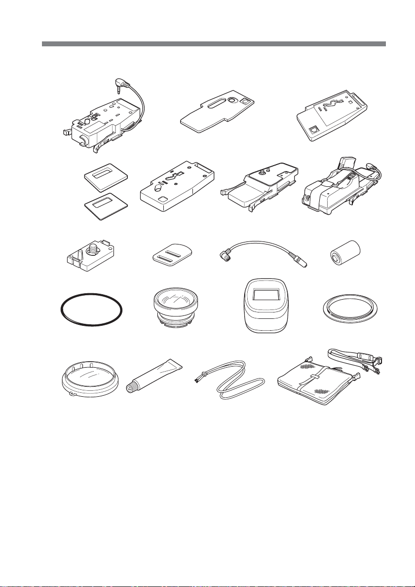
Supplied Accessories
Check that the following accessories are supplied with your marine pack.
123
B
4567
Thick
Thin
890qa
qs qd qf qg
qh qj qk
1 Camera mounting shoe B (1)
2 Spacer C (1)
3 Camera mounting shoe D (1)
4 Cushions for camera mounting shoe
D (2)
5 Camera mounting shoe E (1)
6 Camera mounting shoe F (1)
7 Camera mounting shoe G (1)
8 Screw plate for camera mounting
shoe B, D and E (2)
9 Screw driver part (1)
Attachment for the camera mounting
shoe B
4-GB
ql
0 A/V conversion cable (1)
qa Lithium battery CR2 (1)
qs O-ring (1)
qd Underwater wide-conversion lens
(VCL-MK2) (1)
qf Sunshade (1)
qg Reflex prevention ring (3)
Large: ø 37 mm (1)
Medium: ø 30 mm (1)
Small: ø 25 mm (1)
qh Colour filter (VF-MK2) (1)
qj Grease (1)
qk Strap (3)
ql Carrying bag (1) Carrying belt (1)
Page 5

Preparations
Preparing your camcorder
Before installing your camcorder in the marine pack, prepare the camcorder according
to this chapter.
The procedure may be different depending on your camcorder type.
For details, please refer to the operating instructions supplied with your camcorder.
You can also install camcorder models different to the one shown in the illustration.
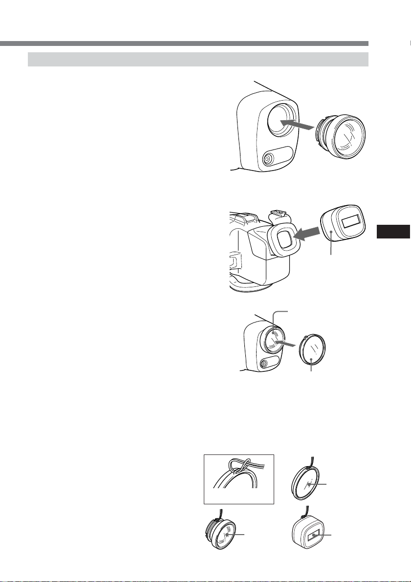
1 Remove the lens cap, shoulder strap, conversion lens, filter or lenshood from
the camcorder.
2 Attach a fully charged battery pack.
Some models can be fitted to a mounting shoe.
3 Insert a cassette tape or “Memory Stick”.
Select the media you want to record onto.
4 Attach the reflex prevention ring to the lens.
for DCR-TRV50/TRV50E/TRV40/TRV40E/TRV30/TRV30E/TRV20/TRV20E/
TRV9/TRV9E : ø 37 mm (large)
for DCR-TRV118E/TRV116E/TRV27/TRV27E/TRV25/TRV25E/TRV24E/TRV18/
TRV18E/TRV17/TRV17E/TRV16/TRV16E/TRV15/TRV15E/TRV11/TRV11E/
TRV10/TRV10E/TRV8/TRV8E/TRV6/TRV6E : ø 30 mm (medium)
for DCR-TRV900/TRV900E/TRV890E : not necessary
for DCR-HC40/HC40E/HC30/HC30E/HC20/HC20E/HC18E/HC16E/PC109/
PC109E/PC108/PC108E/PC107E/PC106E : ø 25 mm (small)
Be sure not too tighten prevention ring.
GB
continued
5-GB
Page 6
Preparations (continued)
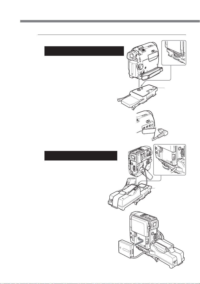
5 Attach the camera mounting shoe.
For DCR-HC40/HC40E/HC30/HC30E/
HC20/HC20E/HC18E/HC16E
Use mounting shoe F and the A/V
conversion cable.
1 Attach mounting shoe F firmly to the
camcorder.
2 Connect the A/V conversion cable to the
camcorder’s AUDIO/VIDEO jack.
F
6-GB
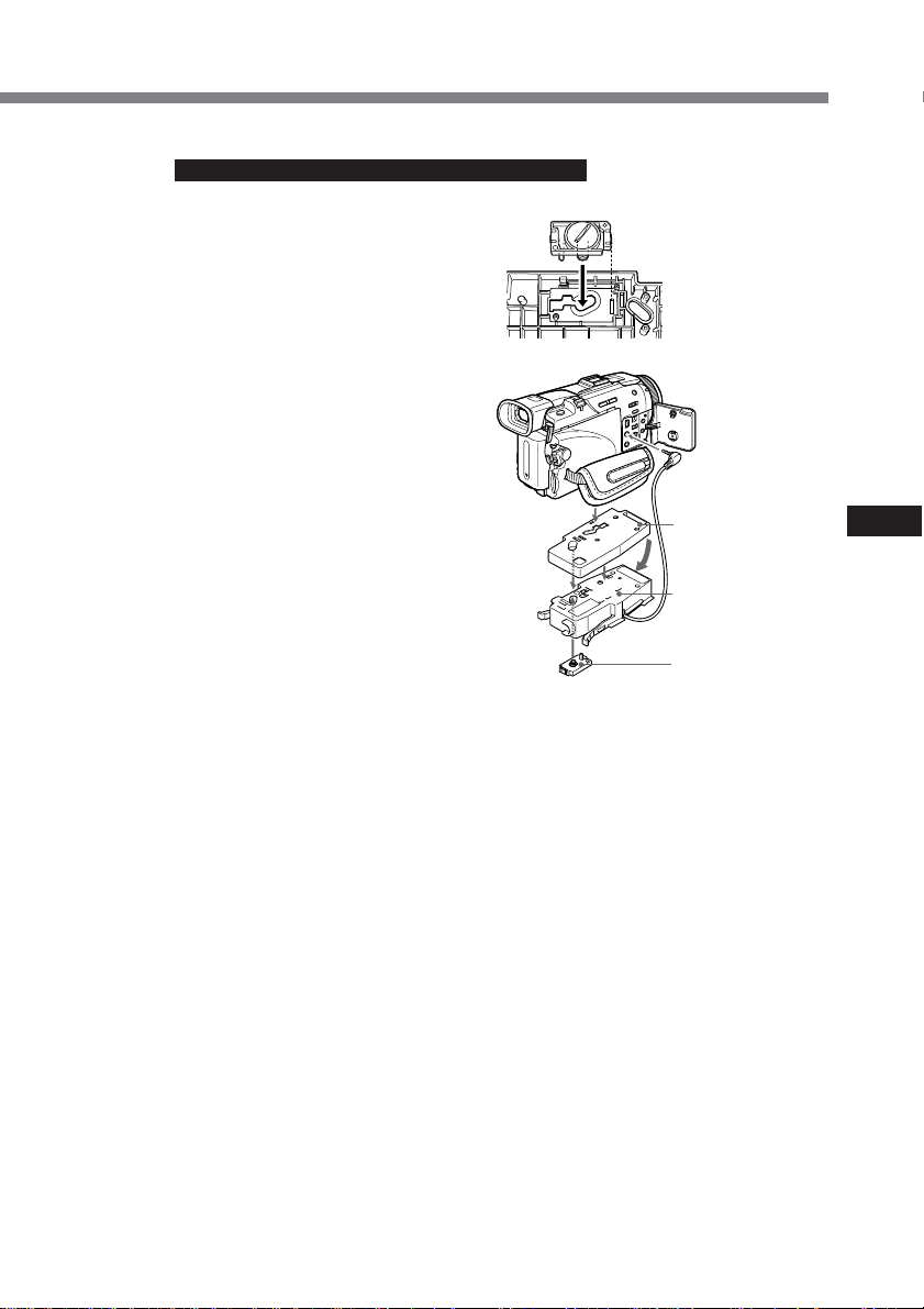
For DCR-PC109/PC109E/PC108/
PC108E/PC107E/PC106E
Use mounting shoe G only.
1 Attach mounting shoe G firmly to the
camcorder.
2 Connect the A/V connecting cable of the
shoe to the camcorder’s AUDIO/VIDEO
jack.
3 Attach the battery adaptor that comes
with mounting shoe G to battery
terminal of the camcorder.
If there is a battery installed in the
camcorder, remove it.
4 Attach the battery to the rear of
mounting shoe G A.
Fasten the battery firmly with the belt,
as shown in the illustration.
G
A
Page 7
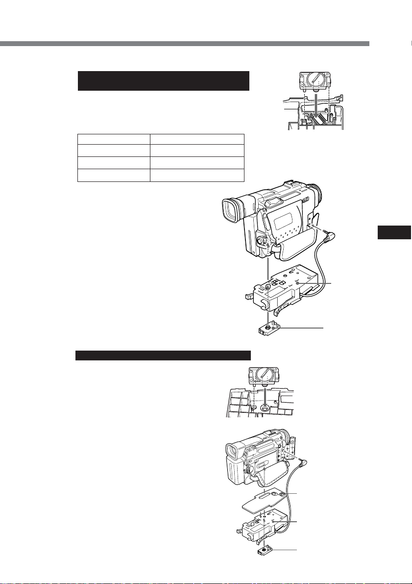
For DCR-TRV900/TRV900E/TRV890E/
TRV9/TRV9E
Use camera mounting shoe B and the screw
plate.
Check the installing position of the screw plate
for your camcorder against the table below.
DCR- Camera mounting Shoe B
TRV900/TRV900E 2
TRV890E 2
TRV9/TRV9E 1
1 Attach the screw plate to
position 1 on shoe B so that the
catch on the reverse side of the
shoe clicks into place.
2 Fasten the screw of the screw
plate to the tripod screw hole of
the camcorder and tighten
firmly.
3 Connect the A/V connecting
cable of the shoe to the
camcorder’s AUDIO/VIDEO
jack.
For DCR-TRV10/TRV10E/TRV8/TRV8E
Use camera mounting shoe B,
spacer C, and the screw plate.
1 Attach the spacer C to shoe B.
2 Attach the screw plate to
position 3 on shoe B so that the
catch on the reverse side of the
shoe clicks into place.
3 Fasten the screw of the screw
plate to the tripod screw hole of
the camcorder and tighten
firmly.
4 Connect the A/V connecting
cable of the shoe to the
camcorder’s AUDIO/VIDEO
jack.
Installation position
of the screw plate
on the camera
mounting shoe B
3
1
GB
Camera
mounting
shoe B
Screw plate
Installation
position
of the screw plate
on the camera
mounting shoe B
Spacer C
Camera mounting
shoe B
Screw plate
continued
7-GB
Page 8
Preparations (continued)
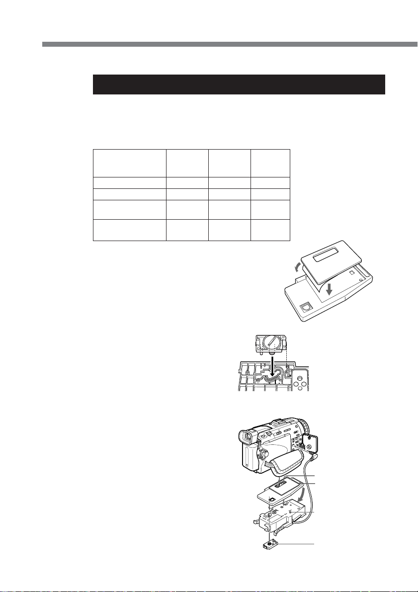
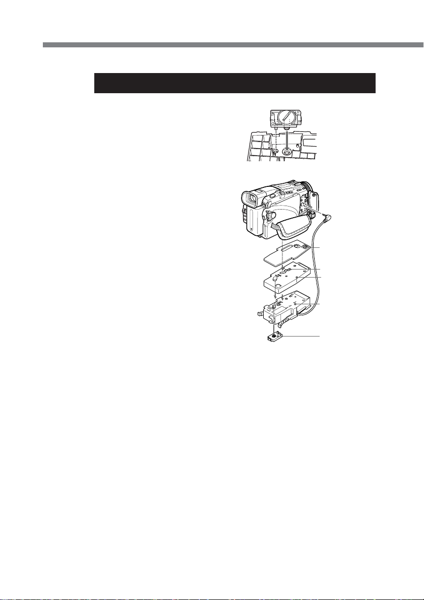
For DCR-TRV30/TRV30E/TRV20/TRV20E/TRV17/TRV17E/TRV15/
TRV15E/TRV11/TRV11E/TRV6/TRV6E
Use camera mounting shoe B and D, cushions for camera mounting shoe D and the
screw plate.
Before attaching the camcorder
Check the cushions for camera mounting shoe D and the installing position of the
screw plate for your camcorder against the table below.
Camera Camera
DCR- mounting mounting Cushion
TRV30/TRV30E 2 1 Thick
TRV20/TRV20E 2 1 Thin
TRV17/TRV17E/
TRV15/TRV15E
TRV11/TRV11E/
TRV6/TRV6E
Remove the stick tape from the
cushion for camera mounting shoe
D. Then stick the cushion for
camera mounting shoe D onto
camera mounting shoe D as shown
in the illustration.
shoe B shoe D
23Thin
22Thin
8-GB
1 Attach the screw plate to the
position on shoe D so that the
catch on the reverse side of the
shoe D clicks into place.
The installing position of the
screw plate differs on your
camcorder. For details, refer to
the table above.
2 Fasten the screw of the screw
plate on shoe D to the tripod
screw hole of the camcorder and
tighten firmly.
3 Attach the screw plate to the
position 2 on shoe B.
4 Fasten the screw of the screw
plate on the shoe B to the screw
hole on the shoe D of the
camcorder tightly.
5 Connect the A/V connecting
cable of the shoe to the
camcorder’s AUDIO/VIDEO
jack.
Installation
position
of the screw plate
of the camera
mounting shoe D
Screw plate
Camera mounting
shoe D
Camera mounting
shoe B
Screw plate
Page 9
For DCR-TRV50/TRV50E/TRV40/TRV40E
Use camera mounting shoe B, E and the screw plate.
1 Attach the screw plate to
position 1 on shoe E so that the
catch on the reverse side of the
shoe clicks into place.
2 Fasten the screw of the screw
plate on shoe E to the tripod
screw hole of the camcorder and
tighten firmly.
3 Attach the screw plate to
position 2 on shoe B.
4 Fasten the screw of the screw
plate on the shoe B to the screw
hole on the shoe E of the
camcorder tightly.
5 Connect the A/V connecting
cable of the shoe to the
camcorder’s AUDIO/VIDEO
jack.
Installation
position
of the screw plate
on the camera
mounting shoe E
Camera mounting
shoe E
B
Camera mounting
shoe B
Screw plate
GB
continued
9-GB
Page 10
Preparations (continued)
For DCR-TRV118E/TRV116E/TRV27/TRV27E/TRV25/TRV25E/
TRV24E/TRV18/TRV18E/TRV16/TRV16E
Use camera mounting shoe B and E,
spacer C, and the screw plate.
1 Attach the spacer C to shoe E.
Attach the screw plate to
position 2 on shoe E so that the
catch on the reverse side of the
shoe clicks into place.
2 Fasten the screw of the screw
plate on shoe E to the tripod
screw hole of the camcorder and
tighten firmly.
3 Attach the screw plate to
position 2 on shoe B.
4 Fasten the screw of the screw
plate on the shoe B to the screw
hole on the shoe E of the
camcorder tightly.
5 Connect the A/V connecting
cable of the shoe to the
camcorder’s AUDIO/VIDEO
jack.
Installation
position
of the screw plate
3
on the camera
mounting shoe B
Spacer C
Screw plate
Camera mounting
shoe E
Camera mounting
shoe B
10-GB
Screw plate
Now you are ready to install the camcorder to the marine pack.
Be sure to check that the camera mounting shoe is attached to the camcorder
tightly before you install the camcorder to the marine pack.
Page 11

6 Prepare to record.
1 Set the POWER switch to CAMERA.
2 Set COMMANDER to ON in the menu settings.
3 Cancel the following functions: BACK LIGHT, NIGHTSHOT, PROGRAM AE,
flash and Picture effect.
4 Set the FOCUS switch to AUTO.
5 Set DISPLAY to V-OUT/LCD in the menu settings and press the DISPLAY
button on your camcorder before installing the marine pack.
* If your camcorder has REC LAMP in the menu settings, set it to OFF. By using
this function, the light of the lamp is not reflected in the lens. For details, please
refer to the operating instructions supplied with your camcorder.
GB
continued
11-GB
Page 12
Preparations (continued)
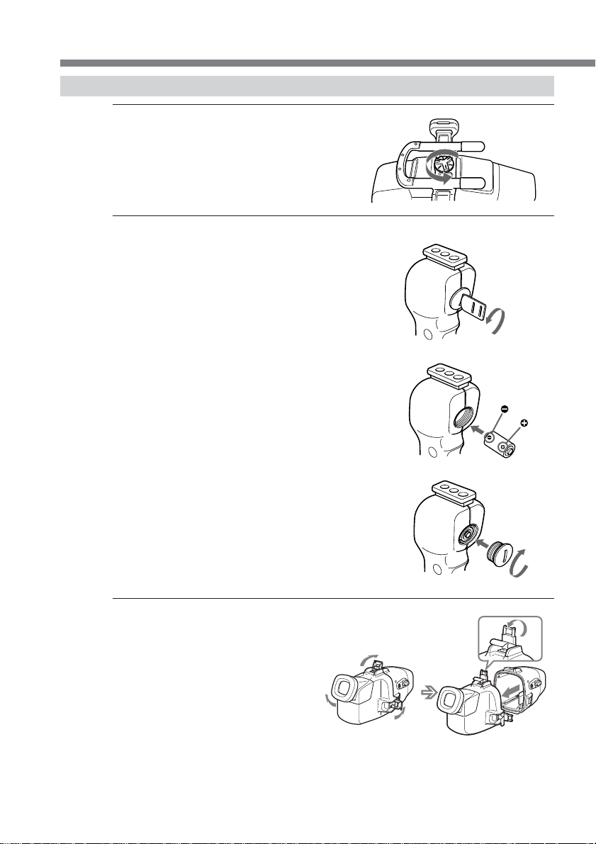
Preparing the marine pack (installing the battery)
1 Remove the grip.
Undo the screw on the bottom side
of the marine pack.
2 Insert the lithium battery into the grip.
1 Remove the screw with the
supplied screw driver.
2 Insert the supplied lithium
battery (CR2, × 1) with the
polarity positioned correctly as
indicated on the grip.
12-GB
3 Fasten the screw tightly.
3 Unfasten the 3 latches and open
the marine pack.
If you lift the metal part in the
direction of the finder when the
latches are open, the latches will
stop.
Page 13

4 Insert the batteries (optional) into the LCD monitor battery compartment.
Use four AA alkali dry batteries or four Ni-MH batteries.
Use new dry batteries.
If you use rechargeable dry batteries, fully charge it before use.
Notes
• Be sure to use four batteries of the same type.
• Be sure to confirm the 3# poles of the batteries. Inserting the batteries with the
poles in the wrong direction may cause leakage or ruptures.
About the LCD monitor
• Install the camcorder to the marine pack and set the POWER switch to ON to make
images appear on the LCD screen.
• The remaining battery time indicator displayed on the LCD monitor refers to
remaining time of the camcorder battery time, not the remaining time of the LCD
monitor battery.
GB
continued
13-GB
Page 14
Preparations (continued)
Installing the camcorder to the marine pack
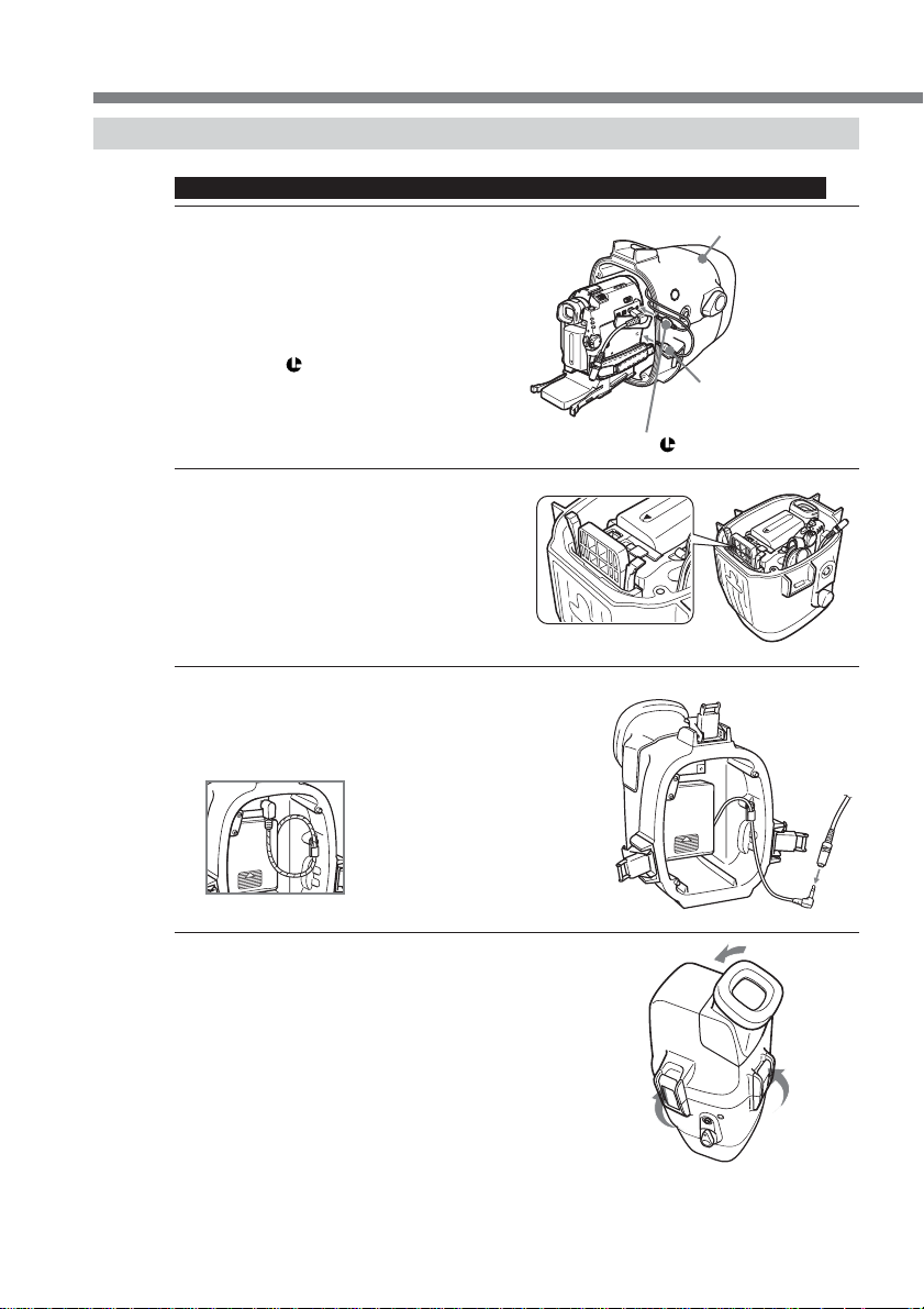
For DCR-HC40/HC40E/HC30/HC30E/HC20/HC20E/HC18E/HC16E
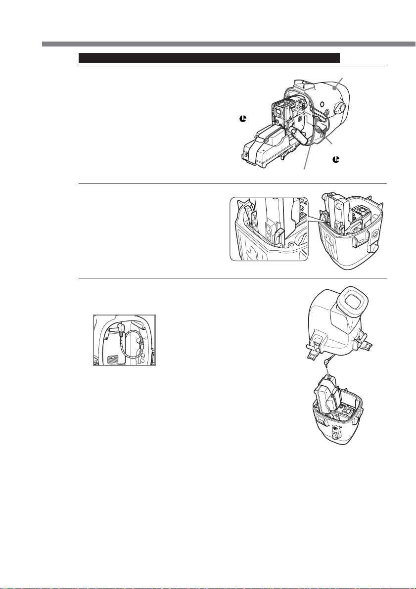
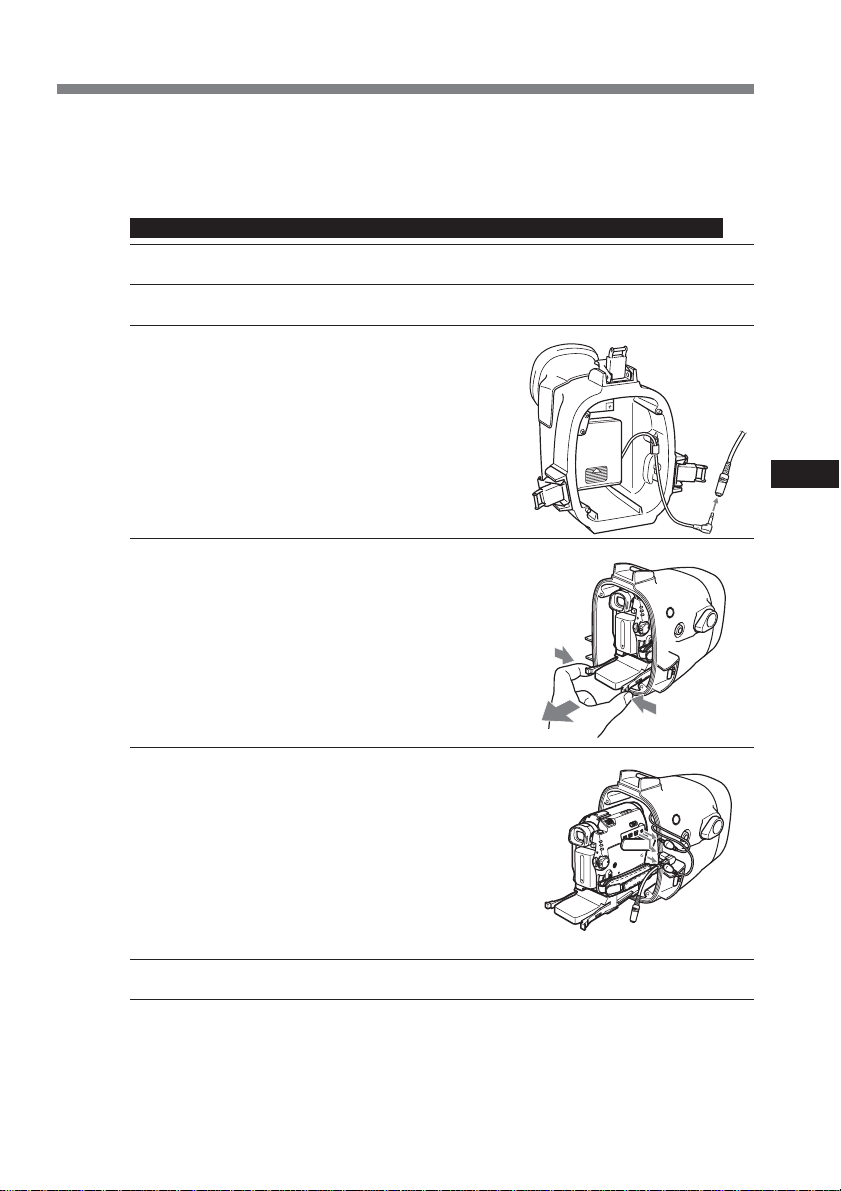
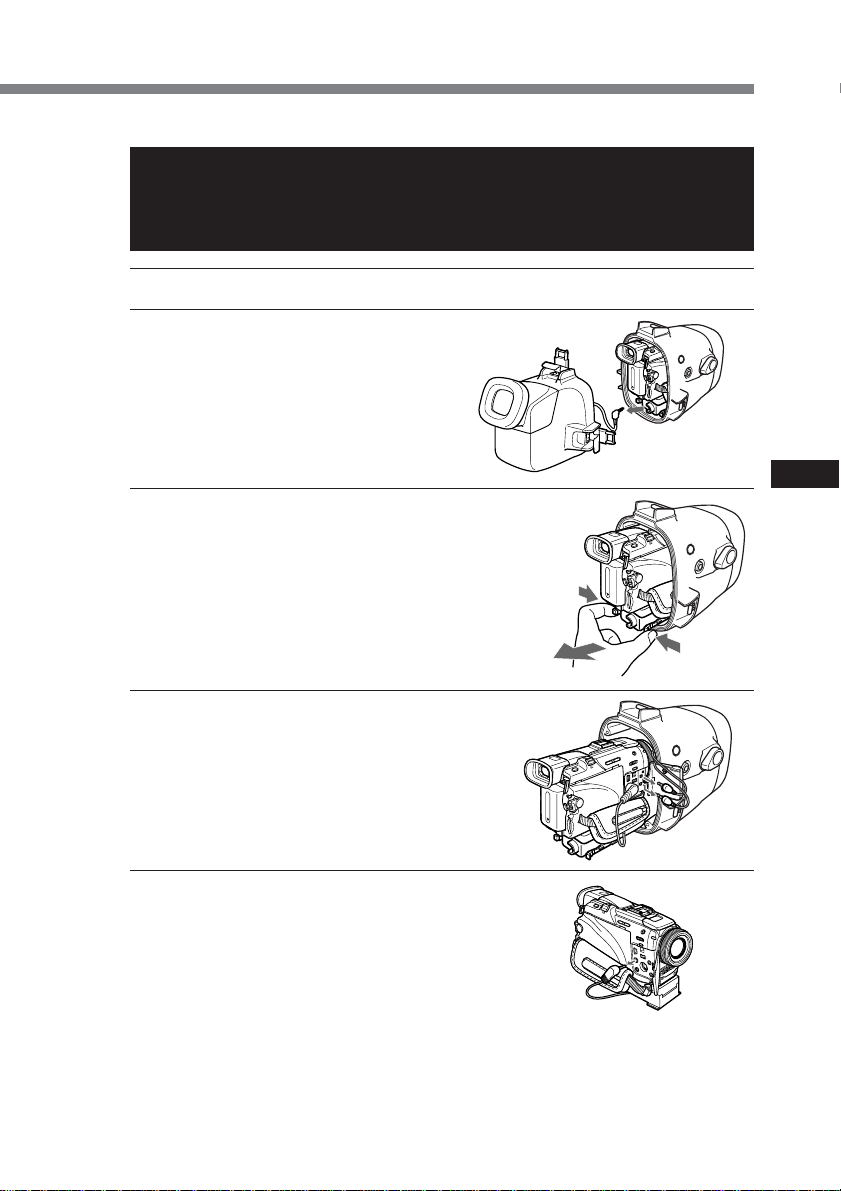
1 Install the camcorder to the marine pack.
Connect the remote plug and the
microphone plug.
1 Connect the microphone plug to the
MIC jack (plug in power).
2 Connect the remote plug to the
LANC jack.
2 to the LANC jack
2 Insert the camcorder until the
mounting shoe clicks into place.
3 Connect the monitor cord to the A/V
conversion cable attached to the
camcorder.
front shell
1 to the MIC jack
(plug in power)
14-GB
The cords are placed in the
plug holders of the marine
pack at the factory. Pull the
plugs out of the holders
when in use.
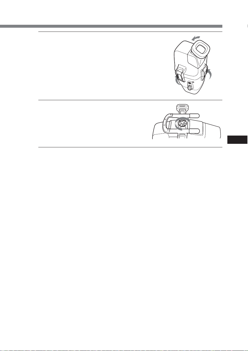
4 Attach the front shell to the rear shell.
Hold both shells firmly and fasten the 3
latches securely.
Take care not to pinch the remote,
microphone, and monitor cords. If this
happens water may leak in.
For details on handling the O-ring, see page
29.
Take care not to pinch the cords.
Page 15

5 Attach the grip.
Fasten the screw tightly.
Now you have finished the preparations.
Be sure to check that the equipment operates correctly and that there is no water
leakage before you dive (see page 20).
GB
continued
15-GB
Page 16
Preparations (continued)
For DCR-PC109/PC109E/PC108/PC108E/PC107E/PC106E
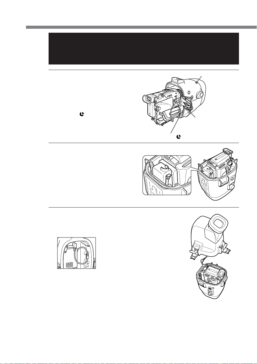
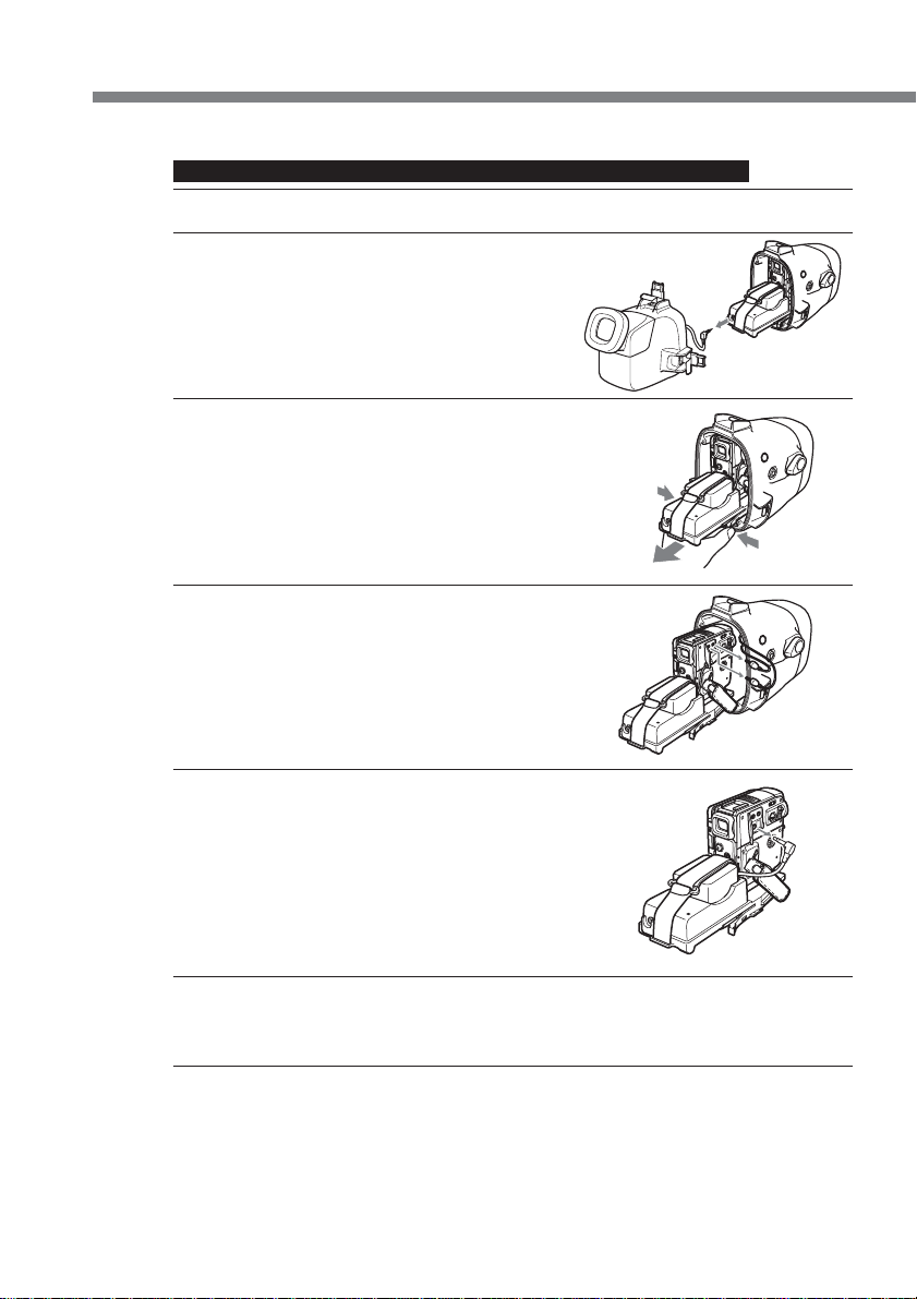
1 Install the camcorder to the marine pack.
Connect the remote plug and microphone plug.
1 Connect the microphone plug to the
MIC jack (plug in power).
2 Connect the remote plug to the LANC
jack.
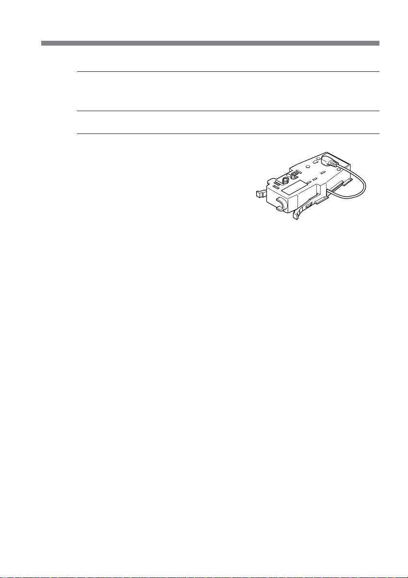
2 Insert the camcorder until the
mounting shoe clicks into place.
3 Connect the monitor cord to the jack of
camera mounting shoe G.
front shell
2 to the LANC
jack
1 to the MIC jack (plug in power)
16-GB
The cords are placed in the
plug holders of the marine
pack at the factory. Pull the
plugs out of the holders when
in use.
Page 17
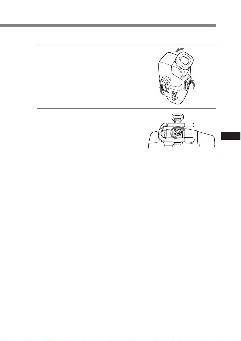
4 Attach the front shell to the rear shell. Hold both
shells firmly and fasten the 3 latches securely.
Take care not to pinch the remote, microphone, and
monitor cords. If this happens water may leak in.
For details on handling the O-ring, see page 29.
Take care not to pinch the cords.
5 Attach the grip.
Fasten the screw tightly.
Now you have finished the preparations.
Be sure to check that the equipment operates correctly and that there is no water
leakage before you dive (see page 20).
GB
continued
17-GB
Page 18
Preparations (continued)
For DCR-TRV900/TRV900E/TRV890E/TRV118E/TRV116E/TRV50/
TRV50E/TRV40/TRV40E/TRV30/TRV30E/TRV27/TRV27E/TRV25/
TRV25E/TRV24E/TRV20/TRV20E/TRV18/TRV18E/TRV17/TRV17E/
TRV16/TRV16E/TRV15/TRV15E/TRV11/TRV11E/TRV10/TRV10E/
TRV9/TRV9E/TRV8/TRV8E/TRV6/TRV6E
1 Install the camcorder to the marine pack.
Connect the remote plug and the
microphone plug.
1 Connect the microphone plug to
the MIC jack (plug in power).
2 Connect the remote plug to the
LANC jack.
2 to the LANC jack
2 Insert the camcorder until the
mounting shoe clicks into place.
3 Connect the monitor cord to the
jack of camera mounting shoe B.
The cords are placed in the
plug holders of the marine
pack at the factory. Pull the
plugs out of the holders when
in use.
front shell
1 to the MIC jack
(plug in power)
18-GB
Page 19
4 Attach the front shell to the rear shell.
Hold both shells firmly and fasten the 3
latches securely.
Take care not to pinch the remote,
microphone, and monitor cords. If this
happens water may leak in.
For details on handling the O-ring, see page
29.
5 Attach the grip.
Fasten the screw tightly.
Now you have finished the preparations.
Be sure to check that the equipment operates correctly and that there is no water
leakage before you dive (see page 20).
GB
19-GB
Page 20

Underwater recording
Before diving
Check for water leakage.
Check that the equipment operates correctly and that there is no water leakage at a
depth of about one meter (3 feet) before you dive deeper.
Take care not to expose the equipment to salty air. Do not drop water on the equipment.
Do not open the marine pack underwater or on the beach. Preparations such as
installing and checking the equipment should be done in a place with low humidity and
no salty air.
Check the following points again before you dive.
s Be sure to fully charge the battery pack for the camcorder.
Be sure that the dry battery for the monitor is not old.
• We recommend you use battery packs with a large capacity and prepare a spare
battery and dry batterys.
s Be sure that a video tape and “Memory Stick” have enough left.
s Check that there are no scratches or cracks on the O-ring.
s Make sure there is no dust, sand, or hair between the front shell and the rear shell.
s Be sure that the lithium battery has enough power.
• If the remaining battery capacity
is enough, when you press the
ZOOM, PHOTO, or START/
STOP button, the Flash lamp
lights up. Check this indicator as
a criterion. If the flash lamp does
not light, exchange for a new
one. We suggest that you
prepare spare ones.
Battery
check
indicator
Right
grip
20-GB
Conditions of underwater recording
Recording underwater is different from recording on land because it is affected by
the clarity, depth of the water, and the light conditions. The following are hints
for good recording underwater.
Best time for recording
The best recording time is from 10:00 a.m. to 2:00 p.m. When the sun is at its highest,
optimum results can be obtained.
To record is in dark places as the sun does not reach or at night, use a powerful
underwater video light.
Page 21

Subject size underwater
Since the refractive index underwater is higher than that in air, objects appear 1/4
closer, and therefore larger. This phenomenon affects the lens on the camcorder as well
as human the eye. Using the supplied wide-conversion lens is recommended.
Operate the camera with slow and stable motions
When recording, keep your body stable.
An unstable shot will be magnified on the TV screen.
Move the camcorder as slowly as possible. Since most of the objects underwater move,
you can record a good shot without moving the camcorder too much.
Note on recording underwater
Be sure to follow the safety rules for diving, such as diving period and depth.
GB
21-GB
Page 22

Recording
Now you are ready for underwater recording.
When you dive with the camcorder, dive slowly, paying attention to the surrounding
environment. Be careful not to strike the marine pack against Rocks or Reef, etc.
POWER switch
AUTO FOCUS
ON/OFF button
REC lamp
(red)
LEAK lamp
(yellow)
ZOOM button
PHOTO button
START/STOP
button
1 Set the POWER switch to ON.
The camcorder turns on and a picture appears on the LCD monitor.
2 Press START/STOP button to start recording.
The REC lamp (red) lights up during recording.
To stop recording, press START/STOP button again.
To zoom
Press ZOOM button.
Press T for telephoto (subject appears closer) and W for wide-angle (subject appears
further away). You cannot change the zooming speed of the camcorder.
Recording a still image
You can record a still image on a tape or “Memory Stick” by pressing PHOTO button.
(Some models, however, can only record onto a tape, even if a “Memory Stick” can be
inserted.)
Note that pressing PHOTO button lightly does not allow you to check the recorded
image. For more details, refer to the operating instructions supplied with your
camcorder.
22-GB
To keep a subject in focus
Press AUTO FOCUS ON/OFF button to set it to OFF. You can still keep the subject in
focus even if fish swim between the camcorder and the subject. Press AUTO FOCUS
ON/OFF button again to set the camcorder to auto focus mode.
Note
Do not cover the control emitter or detector with your finger as the remote control
signal for operations is transmitted from the grip to the marine pack.
Page 23
Attaching the supplied accessories
Attaching the supplied wide-conversion lens
As objects appear 1/4 closer and
therefore larger, the wide-conversion
lens is recommended when you want to
take pictures of wide areas. Note
however, that objects will appear
smaller.
Note
This supplied wide-conversion lens is
to be used only underwater.
Using the supplied sunshade
The supplied sunshade reduces glare
from the LCD monitor.
Attaching the supplied colour filter
When using the supplied colour filter,
attach it on top of the wide-conversion
lens.
Water absorbs light, especially red
light, so that objects in deep water are
seen bluish. The colour of objects is
affected by the clarity of the water.
To record in natural colour, use the
supplied colour filter.
You can attach and remove the wide-conversion lens, sunshade, and colour filter
underwater.
If the image on the LCD screen is not clear because of air between these accessories and
the marine pack, reattach them underwater.
Attach the wide-conversion lens until it
fits firmly.
GB
Supplied sunshade
Wide-conversion lens
colour filter
Attaching the supplied strap
Attach the strap as the shown.
Attach the supplied straps to prevent
loss of these accessories when
removing them both on land and
underwater. Attach the straps to the
grip of the marine pack.
To attach the strap
Wideconversion
lens
colour filter
Sunshade
continued
23-GB
Page 24
Recording (continued)
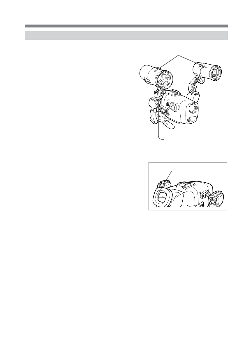
Using the underwater video light (optional)
In deep water or under rocks where
direct sunlight does not reach,
recording with underwater video lights
is recommended.
You can attach these video lights to the
video light shoes on the upper part of
both grips.
Water leakage
The marine pack is designed to be
waterproof, however if water happens
to leak in, the LEAK lamp (yellow)
flashes.
In such a case, remove the marine pack
from the water as soon as possible,
keeping it horizontal. Be sure to surface
following the safety rules for diving.
Dry the marine pack with a soft cloth
and then open it.
To switch off the lamp, disconnect the remote control cable.
Check the cause of the leak.
Underwater video lights such as the
Sony HVL-ML20M (optional)
Attachable to the video light
shoes on both sides
LEAK lamp (yellow)
24-GB
If the camcorder is wet, take it to the nearest Sony dealer immediately.
We recommend you purchase property damage insurance for underwater materials in
case of emergency.
After using
• After recording in the sea, submerge the marine pack in tap water or fresh water for
about 30-60 minutes before undoing the latches to completely remove any salt from
the marine pack unit, filter, and wide-conversion lens.
• When your camcorder is to be used near the sea for a long time, we recommend that
it be checked periodically by the nearest Sony dealer.
Page 25
Removing the camcorder
Before opening the marine pack, rinse it with fresh water and dry with a soft cloth.
When you open the marine pack, make sure you are dry. And take care that no water
drips from your wet suit.
For DCR-HC40/HC40E/HC30/HC30E/HC20/HC20E/HC18E/HC16E
1 Remove the grip.
2 Unfasten 3 latches and open the marine pack.
3 Disconnect the monitor cord from the
A/V conversion cable.
4 Take the camcorder out of the front shell.
Hold the camera mounting shoe by the knobs and
extract the camcorder.
When you open the marine pack, do not pull the
monitor plug cord by force.
GB
5 Disconnect the remote plug, the
microphone plug and the A/V
conversion cable.
6 Remove the mounting shoe from the camcorder.
7 Remove the batteries from the LCD monitor battery compartment.
continued
25-GB
Page 26
Removing the camcorder (continued)
For DCR-PC109/PC109E/PC108/PC108E/PC107E/PC106E
1 Remove the grip.
2 Unfasten 3 latches and open the marine pack.
Disconnect the monitor cord from the
camera mounting shoe G.
3 Take the camcorder out of the front shell.
Hold the camera mounting shoe by the
knobs and extract the camcorder.
When you open the marine pack, do not
pull the monitor plug cord by force.
4 Disconnect the remote plug and the
microphone plug.
26-GB
5 Disconnect the A/V connecting cable of
camera mounting shoe G from the
AUDIO/VIDEO jack.
6 Remove the battery adaptor from the camcorder before removing the
mounting shoe.
Also remove the battery attached to the rear of mounting shoe G.
7 Remove the batteries from the LCD monitor battery compartment.
Page 27
For DCR-TRV900/TRV900E/TRV890E/TRV118E/TRV116E/TRV50/
TRV50E/TRV40/TRV40E/TRV30/TRV30E/TRV27/TRV27E/TRV25/
TRV25E/TRV24E/TRV20/TRV20E/TRV18/TRV18E/TRV17/TRV17E/
TRV16/TRV16E/TRV15/TRV15E/TRV11/TRV11E/TRV10/TRV10E/
TRV9/TRV9E/TRV8/TRV8E/TRV6/TRV6E
1 Remove the grip.
2 Unfasten 3 latches and open the
marine pack.
Disconnect the monitor cord from
the camera mounting shoe B.
3 Take the camcorder out of the
front shell.
Hold the camera mounting shoe by
the knobs and extract the
camcorder.
When you open the marine pack,
do not pull the monitor plug cord
by force.
4 Disconnect the remote plug and
the microphone plug.
GB
5 Disconnect the A/V connecting
cable of camera mounting shoe B
from the AUDIO/VIDEO jack.
continued
27-GB
Page 28
B
Removing the camcorder (continued)
6 Remove the camera mounting shoe with the screw driver.
Undo the screw of the screw plate and remove the camera mounting shoe from the
camcorder.
7 Remove the batteries from the LCD monitor battery compartment.
After using the marine pack
Insert the A/V connecting cable plug to
the plug holder of the camera mounting
shoe B.
28-GB
Page 29
Note on the O-ring
What is an O-ring?
• An O-ring is part of the water-proof packing that is used on underwater cameras,
watches, and other diving equipments.
• The O-ring acts to preserve the waterproof qualities of the marine pack and other
equipments.
O-ring
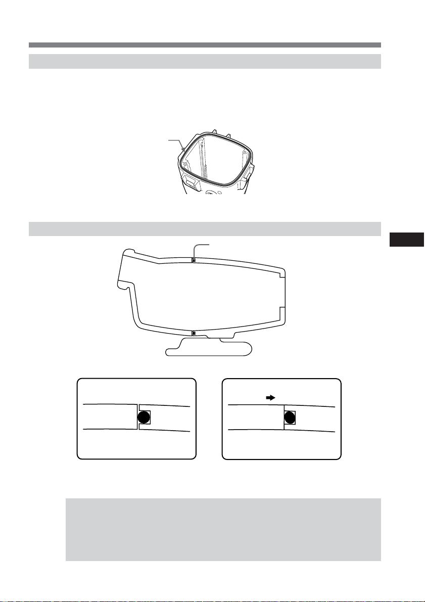
How the O-ring waterproofs
O-ring
GB
The surface of the O-ring contacts the rubber to prevent water from entering the gap.
water
When water pressure acts on the O-ring, the contact surface area of the
O-ring expands to increase the force acting on the groove on the marine pack.
water
pressure
O-ring maintenance is very important. If O-ring maintenance
is not followed according to instructions, this might cause a
water leak, and cause the marine pack to sink. The surface
of the O-ring contacts the entire rubber evenly to prevent
water from entering the gap.
continued
29-GB
Page 30
Note on the O-ring (continued)
Handling the O-ring
Set the O-ring in place
Avoid setting the O-ring in dusty or sandy locations.
1 Remove the O-ring.
Do not use pointed or metal objects to remove the O-ring. These objects might
scratch or damage the marine pack groove or O-ring.
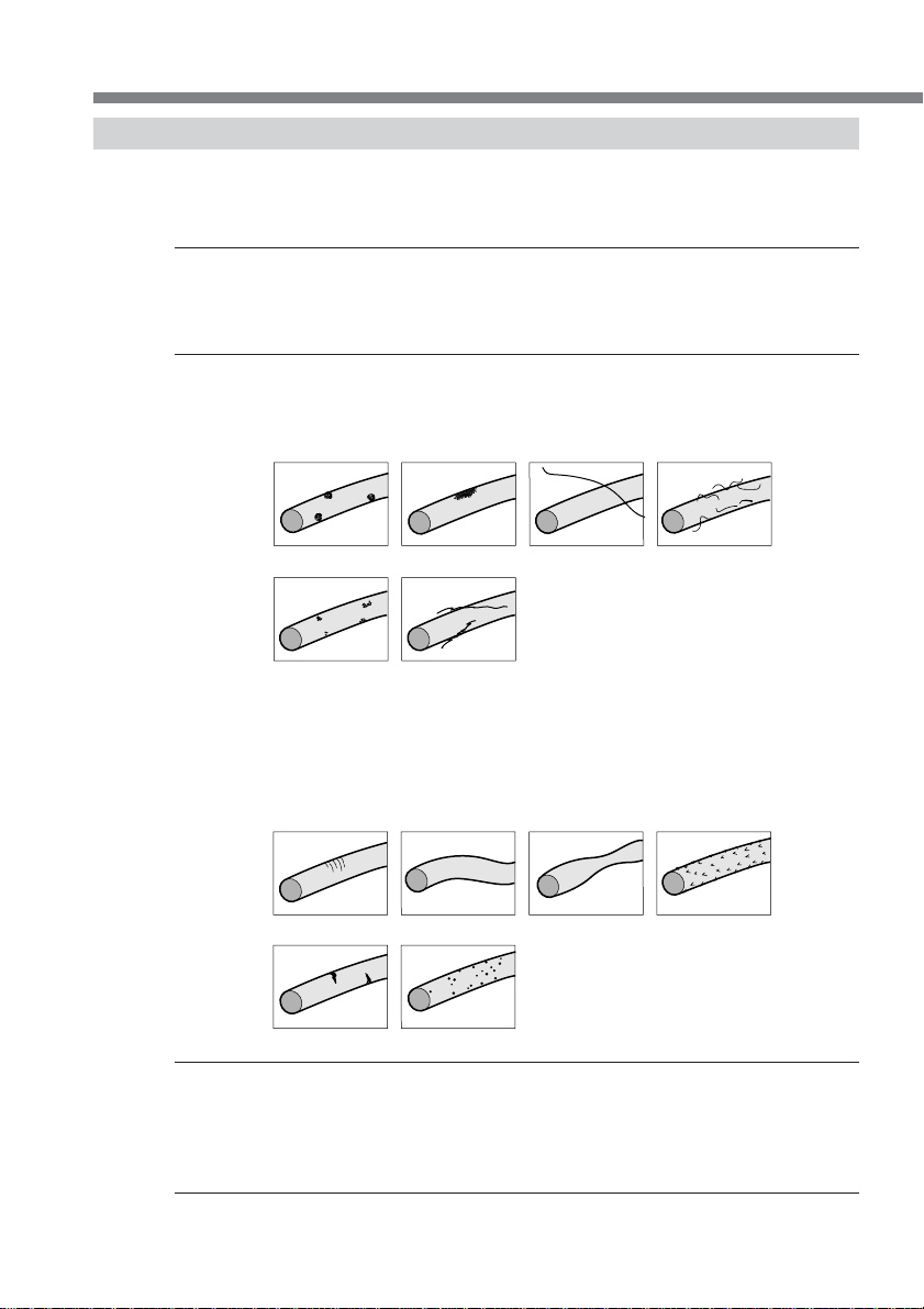
2 Inspect the O-ring.
•Fully check the following, and wipe off with a soft cloth or tissue paper.
– Check for any dirt, grains of sand, hair, dust, salt, thread scraps, etc.
– Check for any old grease.
v Dirt v Sand v Hair v Dust
30-GB
v Salt v
•Lightly run your fingertip around the O-ring to check for any unapparent
dirt.
•After wiping the O-ring, take care to prevent any cloth or tissue paper fibres
from remaining on the O-ring.
•Check the O-ring for cracking, skew, distortion, fine splitting, scratches,
sand-biting, etc. Replace cracked or scratched O-rings.
v Cracking v Skew v Distortion v Fine
v Scratches v Sand-biting
Thread scraps
Splitting
3 Inspect the O-ring groove.
Grains of sand or hardened salt sometimes get into the groove. Carefully remove
them by blowing with an air spray or by wiping them with a cotton wool bud.
Prevent fibre scraps from the cotton wool bud from entering inside.
4 Also, inspect the contacting surface on the other side of the O-ring in the same
way.
Page 31

5 Apply a coating of grease to the O-ring.
•Apply a small drop of grease onto the O-ring and evenly coat the entire surface of
the O-ring with the end of your finger.
•Do not use paper or cloth as fibre may stick to the O-ring.
•Make sure that a thin coating of grease is applied to the surface of the O-ring at all
times. Grease protects the O-ring, and prevents wear.
•After you have applied a small drop of grease onto the O-ring, set the O-ring
immediately. Do not leave the greased O-ring on a desk or other surfaces.
6 Place the O-ring in the groove on the marine pack.
Place the O-ring evenly in its groove paying attention to the following points:
– Is there any dirt on the O-ring?
– Is the O-ring twisted?
– Do not pull the O-ring.
– Is the O-ring protruding?
Bad example Good example
Final check
After you have fitted in the O-ring, check it again for the following:
– Is the O-ring twisted?
– Is there any dirt on the O-ring?
– Is the O-ring protruding?
– Are there any cracking or distortion on the O-ring?
How to check for water leaks
After you have replaced the O-ring, close the marine pack before you insert the
equipment you are using. Immerse the marine pack for about three minutes in water to
a depth of about 15 cm, and check for water leaks.
PCAUTION
When you have taken photos on a sandy sea bottom or have placed the camera on the
sand, remove the O-ring and check for water leaks.
Be sure to take a spare O-ring with you.
This facilitates replacement even if O-ring trouble occurs
where you are taking photos.
GB
continued
31-GB
Page 32

Note on the O-ring (continued)
Maintenance
After you have finished using an O-ring
• After you have used the marine pack, be sure to perform the following:
– Wash the marine pack with fresh water with the buckle closed to remove salt or
sand.
– Insert the marine pack in fresh water for about 30 minutes with the buckle closed.
If salt is left on the marine pack, metal parts and the O-ring might be damaged, and
cause water leaks.
– When sun oil is stuck to the marine pack, wash off with lukewarm water.
If sun oil is left on the marine pack, the surface of the marine pack might become
discoloured or become damaged.
– Wipe the inside of the marine pack with a soft, dry cloth. Do not wash with water.
• Remove the O-ring each time that you have finished using it, and check it.
If the marine pack is dried with sea water still in the O-ring groove, salt crystals form,
and might impair the O-ring’s functions.
• Do not use thinner, benzene, alcohol or other solvents as they will damage the
surface finish.
Storing O-rings
• Prevent dust from sticking to O-rings.
• Apply a thin coating of grease to the O-ring, set it in the groove, and store in a well-
ventilated location. Do not close the buckle.
• Avoid storing O-rings in hot, cold or humid locations, and placing in naphthalene or
camphor. These locations and solutions will damage the materials.
How to store O-rings
• To maintain the O-ring’s functions, avoid storing them in hot locations or in the
direct sunlight.
• Do not place the spare O-ring under heavy objects. Doing so might deform the
O-ring.
32-GB
O-ring life
Replace the O-ring with a new one after one year of use.
Even if the O-ring is not cracked or scratched, deformation or wear reduces the
waterproof qualities of the O-ring. Replace the O-ring with a new one if cracking, skew,
distortion, fine splitting, scratches, sand-biting, etc. is found.
Grease
Use the supplied grease. Using other manufacturer’s grease
will damage the O-ring, and cause water leaks.
O-ring and grease
You can obtain O-rings and grease at your nearest Sony dealer.
O-ring (model No. 3-977-362-01)
Grease (model No. 3-071-370-01)
Page 33

Caution on handling
After using
The metal parts will rust and the movement of the operation switches will be impaired
if you leave salt water on the marine pack. If sea water enters through scratches in the
coating, the salt can corrode the metal parts of the marine pack unit and cause the
coating to peel off. After recording in the sea, submerge the marine pack in tap water or
fresh water for about 30 minutes before undoing the buckles to completely remove any
salt from the marine pack unit, filter, and wide-conversion lens.
After washing, wipe any water from the inside of the marine pack and the loaded video
camcorder with a soft dry cloth.
* Always follow the above precautions when you use the marine pack.
When you open the marine pack or exchange the battery pack of the grip, take care that
no water drips from your wet suit or hair.
Do not leave the marine pack under direct sunlight for a long period of time, otherwise
the temperature in the marine pack may rise and the equipment inside may be
damaged. If you cannot avoid leaving the marine pack under direct sunlight, be sure to
cover the marine pack with a towel or other protection.
When you store the marine pack
Coat the O-ring slightly with the supplied grease, and put it in the groove correctly.
Join the front and rear shells then put it in a cool and dry place without fastening the
buckles.
Avoid storing the marine pack in a very hot, cold, or humid place, or together with
naphthalene or camphor, as these conditions might damage the unit.
On transportation
When transporting the marine pack, be sure to remove your camcorder from it.
Otherwise this might damage the unit.
Note
When you use the supplied carrying
bag, attach the supplied carrying belt
and adjust the length of the belt.
Avoid rough handling or a shock. We
recommend covering the marine pack
with a towel or other protection.
GB
33-GB
Page 34

Identifying parts and controls
Monitor plug
Rear shell
LCD monitor
battery
compartment
Lithium battery
compartment
Remote control
detector
Grip
AUTO FOCUS
ON/OFF button
Remote plug (blue)
REC lamp (red)
LEAK lamp (yellow)
LCD
monitor
Guide rail
Remote
control
transmitter
Battery
check
indicator
Front shell
Video light shoe
Front glass
Underwater
microphone
(monaural)
POWER switch
O-ring
ZOOM buttons
PHOTO button
START/STOP
button
Spacer C
Camera mounting shoe B
Camera mounting
34-GB
shoe F
Screw plate
Camera mounting shoe D
Battery adaptor
Belt
B
Camera
mounting shoe G
A/V connecting cable
Cushions for camera
mounting shoe D
A/V conversion cable
A/V connecting cable
Microphone plug
Camera
mounting shoe E
Page 35

Specifications
Material
Aluminum alloy, glass, plastic (ABS, PC)
Waterproofing
O-ring, 3 latches
Usable depth
Up to 75 m (246 feet)
Underwater microphone
Condenser microphone (monaural)
Controllable function
Power on/off, recording start/stop, auto focus on/off, power zooming,
tape photo recording
Dimensions
Approx. 312 × 212 × 318 mm (w/h/d)
(12 3/8 × 8 3/8 × 12 5/8 in.)
Mass
Approx. 4.4 kg (9 lb 11 oz) (the unit only)
Supplied accessories
Camera mounting shoe B, D, E, F, G (1 each)
Spacer C (1)
Cushions for camera mounting shoe D (2)
Screw plate (2)
Screw driver part (1)
A/V conversion cable (1)
Wide-conversion lens (1)
Colour filter (1)
Lithium battery CR2 (1)
Grease (1)
O-ring (1)
Sunshade (1)
Reflex prevention ring (3)
Strap (3)
Carrying bag (1)
Carrying belt (1)
Operating instructions (1)
Warranty (1)
Recommended accessory
Underwater video light HVL-ML20M
GB
Design and specifications are subject to change without notice.
35-GB
Page 36

Table des matières
Fonctions et précautions ............................. 2
Accessoires fournis ...................................... 3
Préparatifs ..................................................... 4
Préparation du caméscope .................. 4
Préparation du caisson étanche
(installation de la pile) ........................ 11
Installation du caméscope dans le
caisson étanche .................................... 13
Enregistrement sous-marin ...................... 19
Enregistrement ........................................... 21
Fixation des accessoires fournis ........ 22
Utilisation d’une lampe vidéo sous-
marine (en option) .............................. 23
Fonctions et précautions
• Le modèle MPK-DVF6 peut être utilisé avec les caméscopes Sony Handycam Vision
DCR-HC40/HC40E/HC30/HC30E/HC20/HC20E/HC18E/HC16E/PC109/
PC109E/PC108/PC108E/PC107E/PC106E/TRV900/TRV900E/TRV890E/TRV118E/
TRV116E/TRV50/TRV50E/TRV40/TRV40E/TRV30/TRV30E/TRV27/TRV27E/
TRV25/TRV25E/TRV24E/TRV20/TRV20E/TRV18/TRV18E/TRV17/TRV17E/
TRV16/TRV16E/TRV15/TRV15E/TRV11/TRV11E/TRV10/TRV10E/TRV9/
TRV9E/TRV8/TRV8E/TRV6/TRV6E.
• Il est possible d’enregistrer à des profondeurs allant jusqu’à 75 mètres.
• Les opérations suivantes peuvent être effectuées sous l’eau:
– Mise sous/hors tension de l’appareil
– Début/arrêt de l’enregistrement
– Activation/désactivation de la mise au point automatique
– Enregistrement de photos sur une cassette
– Zooming
– Contrôle sur l’écran LCD
Retrait du caméscope ................................ 24
Remarque concernant le joint torique .... 28
Qu’est-ce qu’un joint torique ? .......... 28
De quelle façon le joint torique
assure-t-il l’étanchéité ? ...................... 28
Maniement du joint torique............... 29
Entretien ............................................... 31
Précaution d’emploi .................................. 32
Identification des pièces et des
commandes ................................................. 33
Spécifications .............................................. 34
™
2-FR
Sony ne peut être tenu responsable des dégâts causés au caméscope, aux piles, aux
autres équipements installés dans le caisson étanche, ni de la perte des données
enregistrées en cas de fuite due à une mauvaise manipulation.
Page 37

Accessoires fournis
Vérifiez si vous avez reçu les accessoires suivants avec le caisson étanche.
123
B
4567
Epais
Fin
890qa
qs qd qf qg
FR
qh qj qk
1 Support de montage de caméscope B (1)
2 Espaceur C (1)
3 Support de montage de caméscope D (1)
4 Tampons pour le support de montage
D (2)
5 Support de montage de caméscope E
(1)
6 Support de montage de caméscope F
(1)
7 Support de montage de caméscope G
(1)
8 Plaque à vis pour les supports de
montage de caméscope B, D et E (2)
9 Tournevis (1)
Fixation pour le support de montage de
caméscope B
ql
0 Câble de conversion A/V (1)
qa Pile au lithium CR2 (1)
qs Joint torique (1)
qd Objectif grand-angulaire (VCL-MK2) (1)
qf Parasoleil (1)
qg Bague antiréflexion (3)
Grande bague: ø 37 mm (1)
Moyenne bague: ø 30 mm (1)
Petite bague: ø 25 mm (1)
qh Filtre couleur (VF-MK2) (1)
qj Graisse (1)
qk Lanière (3)
ql Sac (1) Bandoulière (1)
3-FR
Page 38

Préparatifs
Préparation du caméscope
Avant d’installer votre caméscope dans le caisson étanche, effectuez les préparatifs
indiqués dans ce chapitre.
Selon le type de caméscope utilisé, la méthode d’installation peut être différente.
Pour obtenir davantage d’informations, reportez-vous au mode d’emploi fourni avec
votre caméscope.
Vous pouvez également installer des modèles de caméscopes différents de celui
présenté sur l’illustration.
1 Retirez le capuchon de l’objectif, la bandoulière, l’objectif grand-angulaire, le
filtre ou le parasoleil du caméscope.
2 Fixer une batterie entièrement rechargée.
Certains modèles peuvent être fixés sur un support de montage.
3 Insérez une cassette ou un « Memory Stick ».
Sélectionnez le support d’enregistrement.
4 Fixez la bague antireflexion sur l’objectif.
pour les modèles DCR-TRV50/TRV50E/TRV40/TRV40E/
TRV30/TRV30E/TRV20/TRV20E/TRV9/TRV9E : ø 37 mm
pour les modèles DCR-TRV118E/TRV116E/TRV27/TRV27E/
TRV25/TRV25E/TRV24E/TRV18/TRV18E/TRV17/
TRV17E/TRV16/TRV16E/TRV15/TRV15E/TRV11/
TRV11E/TRV10/TRV10E/TRV8/TRV8E/TRV6/TRV6E : ø 30 mm
pour les modèles DCR-TRV900/TRV900E/TRV890E : inutile
pour les modèles DCR-HC40/HC40E/HC30/HC30E/
HC20/HC20E/HC18E/HC16E/PC109/PC109E/PC108/
PC108E/PC107E/PC106E : ø 25 mm
Assurez-vous de ne pas trop visser la bague antireflexion.
(grande bague)
(moyenne bague)
(petite bague)
4-FR
Page 39

5 Fixez le support de montage du caméscope.
Pour les modèles DCR-HC40/
HC40E/HC30/HC30E/HC20/
HC20E/HC18E/HC16E
Utilisez le support de montage F et
le câble de conversion A/V.
1 Fixez fermement le support de
montage F sur le caméscope.
2 Branchez le câble de conversion
A/V sur la prise AUDIO/
VIDEO du caméscope.
Pour les modèles DCR-PC109/
PC109E/PC108/PC108E/
PC107E/PC106E
Utilisez uniquement le support de
montage G.
1 Fixez fermement le support de
montage G sur le caméscope.
2 Branchez le câble de conversion
A/V sur la prise AUDIO/
VIDEO du caméscope.
F
US
FR
G
3 Fixezx l’adaptateur de batterie,
fourni avec le support de
montage G, sur la borne de
batterie du caméscope.
Si une batterie est déjà installée
dans le caméscope, retirez-la.
4 Fixez la batterie à l’arrière du
support de montage G A.
Fixez fermement la batterie au
moyen de la courroie, comme
indiqué sur l’illustration.
A
suite
5-FR
Page 40

Préparatifs (suite)
Pour les modèles DCR-TRV900/
TRV900E/TRV890E/TRV9/TRV9E
Utilisez le support de montage B et
la plaque à vis.
Vérifiez dans le tableau suivant la
position de la plaque à vis en
fonction du caméscope.
DCR- Support de montage B
TRV900/TRV900E 2
TRV890E 2
TRV9/TRV9E 1
1 Attachez la plaque à vis sur le
support B, en position 1, de sorte
que l’ergot situé sur l’envers du
support s’encliquette
correctement.
2 Vissez fermement la vis de la
plaque à vis dans le filetage de
trépied du caméscope.
3 Raccordez le câble audio-visuel
du support à la prise AUDIO/
VIDEO du caméscope.
1
Position d’installation
de la plaque à vis sur le
support de montage B
Support de
montage B
6-FR
Pour les modèles DCR-TRV10/
TRV10E/TRV8/TRV8E
Utilisez le support de montage B,
l’espaceur C, et la plaque à vis.
1 Fixez au support B l’espaceur C.
2 Fixez la plaque à vis au support
B en position 3 de telle sorte que
l’ergot situé sur l’envers du
support s’encliquette
correctement.
3 Vissez fermement la vis de la
plaque à vis dans le filetage de
trépied du caméscope.
4 Raccordez le câble audio-visuel
du support à la prise AUDIO/
VIDEO du caméscope.
Plaque à vis
Position
d’installation de la
plaque à vis sur le
3
support de
montage B
Espaceur C
Support de
montage B
Plaque à vis
Page 41

Pour les modèles DCR-TRV30/TRV30E/TRV20/TRV20E/TRV17/
TRV17E/TRV15/TRV15E/TRV11/TRV11E/TRV6/TRV6E
Utilisez les supports de montage B et D, les tampons pour le support de montage D
et la plaque à vis.
Avant de fixer le caméscope
Vérifiez les tampons du support de montage D et la position de fixation de la
plaque à vis nécessaire pour votre caméscope sur le tableau suivant.
Support de Support de
DCR- montage montage Tampon
BD
TRV30/TRV30E 2 1 Epais
TRV20/TRV20E 2 1 Fin
TRV17/TRV17E/
TRV15/TRV15E
TRV11/TRV11E/
TRV6/TRV6E
Détachez la pellicule du tampon de
support de montage D. Collez le
tampon approprié sur le support de
montage D, comme indiqué sur
l’illustration.
23Fin
22Fin
US
FR
1 Fixez la plaque à vis au support
D de telle sorte que l’ergot situé
sur l’envers du support D
s’encliquette correctement.
La position de fixation de la
plaque à vis dépend du
caméscope. Pour de plus amples
informations, reportez-vous au
tableau ci-dessus.
2 Vissez fermement la vis de la
plaque à vis sur le support D
dans le filetage de trépied du
caméscope.
3 Fixez la plaque à vis au support
B, en position 2.
4 Vissez fermement la vis de la
plaque à vis sur le support B
dans le filetage de support D du
caméscope.
5 Raccordez le câble audio-visuel
du support à la prise AUDIO/
VIDEO du caméscope.
Position
d’installation de
la plaque à vis sur
le support de
montage du
caméscope D
Plaque à vis
Support de montage
du caméscope D
Support de montage
du caméscope B
Plaque à vis
suite
7-FR
Page 42

Préparatifs (suite)
Pour les modèles DCR-TRV50/TRV50E/TRV40/TRV40E
Utilisez le support de montage B, E de caméscope et la plaque à vis.
1 Fixez la plaque à vis au support
E en position 1 de telle sorte que
l’ergot situé sur l’envers du
support s’encliquette
correctement.
2 Vissez fermement la vis de la
plaque à vis sur le support E
dans le filetage de trépied du
caméscope.
3 Fixez la plaque à vis au support
B, en position 2.
4 Vissez fermement la vis de la
plaque à vis sur le support B
dans le filetage de support E du
caméscope.
5 Raccordez le câble audio-visuel
du support à la prise AUDIO/
VIDEO du caméscope.
Position
d’installation de la
plaque à vis sur le
support de
montage E
Support de
montage E
B
Support de
montage B
Plaque à vis
8-FR
Page 43

Pour les modèles DCR-TRV118E/TRV116E/TRV27/TRV27E/
TRV25/TRV25E/TRV24E/TRV18/TRV18E/TRV16/TRV16E
Utilisez les supports de montage B
et E, l’espaceur C et la plaque à vis.
1 Fixez l’espaceur C au support de
montage E.
Fixez ensuite la plaque à vis au
support E, en position 2, de sorte
que l’ergot situé sur l’envers du
support s’encliquette
correctement.
2 Vissez fermement la vis de la
plaque à vis sur le support E
dans le filetage de trépied du
caméscope.
3 Fixez la plaque à vis au support
B, en position 2.
4 Vissez fermement la vis de la
plaque à vis sur le support B
dans le filetage de support E du
caméscope.
5 Raccordez le câble audio-visuel
du support à la prise AUDIO/
VIDEO du caméscope.
Vous pouvez maintenant installer le caméscope dans le caisson étanche.
Assurez-vous que le support de montage est bien fixé au caméscope avant
d’installer ce dernier dans le caisson étanche.
3
Position
d’installation de la
plaque à vis sur le
support de
montage B
Espaceur C
Plaque à vis
Support de
montage E
Support de
montage B
Plaque à vis
US
FR
suite
9-FR
Page 44

Préparatifs (suite)
6 Préparation à l’enregistrement.
1 Réglez le commutateur POWER sur CAMERA.
2 Dans les paramètres du menu, réglez COMMANDER sur ON.
3 Désactivez les fonctions suivantes: BACK LIGHT, NIGHTSHOT, PROGRAM
AE, le flash et l’effet d’image.
4 Réglez le commutateur FOCUS sur AUTO.
5 Réglez DISPLAY sur V-OUT/LCD dans les paramètres du menu et appuyez sur
la touche DISPLAY de votre caméscope avant de l’installer dans le caisson
étanche.
* Si le menu comporte le paramètre REC LAMP, réglez-le sur OFF. La lumière de
la lampe ne se réfléchira pas sur l’objectif. Pour obtenir davantage
d’informations, reportez-vous au mode d’emploi fourni avec votre caméscope.
10-FR
Page 45

Préparation du caisson étanche (installation de la pile)
1 Retirez la poignée.
Dévissez la vis située sous le
caisson étanche.
2 Insérez la pile au lithium dans la poignée.
1 Retirez la vis en vous servant du
tournevis fourni.
2 Insérez dans la poignée la pile au
lithium (CR2, × 1) fournie en
respectant la polarité.
3 Vissez fermement.
US
FR
3 Défaites les 3 loquets et ouvrez le
caisson étanche.
Si vous levez la partie métallique
dans la direction du viseur lorsque
les loquets sont défaits, ceux-ci se
bloquent.
suite
11-FR
Page 46

Préparatifs (suite)
4 Insérez les piles (en option) dans le logement de batterie du moniteur LCD.
Utilisez quatre piles alcalines AA ou quatre piles Ni-MH.
Utilisez de nouvelles piles.
Si vous utilisez des piles rechargeables, rechargez-les à fond avant leur emploi.
Remarque
• Pensez à utiliser quatre piles du même type.
• Vérifiez les polarités 3# des piles. Si vous ne respectez pas la polarité des piles,
ces dernières risquent de fuir ou de provoquer un court-circuit.
A propos du moniteur à LCD
• Installez le caméscope dans le caisson étanche et réglez le commutateur POWER sur
ON pour faire apparaître les images sur l’écran LCD.
• L’autonomie affichée sur l’écran LCD concerne la batterie du caméscope et non pas la
pile du moniteur.
12-FR
Page 47

Installation du caméscope dans le caisson étanche
Pour les modèles DCR-HC40/HC40E/HC30/HC30E/HC20/HC20E/
HC18E/HC16E
1 Installez le caméscope dans le
caisson étanche.
Raccordez la fiche de télécommande et la
fiche de microphone.
1 Branchez la fiche de microphone sur la
prise MIC (alimentation par fiche).
2 Branchez la fiche de télécommande sur
la prise LANC .
2 à la prise LANC
2 Insérez le caméscope jusqu’à ce
que le support de montage
s’encliquette.
3 Raccordez le cordon du moniteur
au câble de conversion A/V fixé
sur le caméscope.
Boîtier avant
1 à la prise MIC
(alimentation par
fiche)
US
FR
Les cordons ont été placés
en usine dans les portefiches du caisson étanche.
Retirez les fiches hors des
supports pour les utiliser.
4 Attachez le boîtier avant au boîtier
arrière. Maintenez fermement les deux
boîtiers et verrouillez solidement les 3
loquets.
Veillez à ne pas pincer les cordons de la
télécommande, du microphone et du
moniteur. Sinon, l’eau risque de s’infiltrer
dans l’appareil.
Pour le détail sur le joint torique, reportezvous à la page 28.
Prenez garde de ne pas coincer les
cordons.
suite
13-FR
Page 48

Préparatifs (suite)
5 Fixez la poignée.
Vissez fermement la vis.
Les préparatifs sont terminés.
Vérifiez que l’appareil fonctionne correctement et que l’eau ne s’y infiltre pas
avant de plonger (voir page 19).
14-FR
Page 49

Pour les modèles DCR-PC109/PC109E/PC108/PC108E/PC107E/
PC106E
1 Installez le caméscope dans le caisson étanche.
Raccordez la fiche de télécommande et la
fiche de microphone.
1 Branchez la fiche de microphone sur la
prise MIC (alimentation par fiche).
2 Branchez la fiche de télécommande sur
la prise LANC .
1 à la prise MIC
(alimentation par fiche)
Boîtier avant
2 à la prise
LANC
2 Insérez le caméscope jusqu’à ce
que le support de montage
s’enclenche en place.
3 Branchez le cordon de moniteur sur la
prise du support de montage G de
caméscope.
FR
Les cordons ont été placés en
usine dans les porte-fiches du
caisson étanche. Retirez les
fiches hors des supports pour
les utiliser.
suite
15-FR
Page 50

Préparatifs (suite)
4 Attachez le boîtier avant au boîtier
arrière. Maintenez fermement les deux
boîtiers et verrouillez solidement les 3
loquets.
Veillez à ne pas pincer les cordons de la
télécommande, du microphone et du
moniteur. Sinon, l’eau risque de s’infiltrer
dans l’appareil.
Pour le détail sur le joint torique, reportezvous à la page 28.
Prenez garde de ne pas coincer les
cordons.
5 Fixez la poignée.
Vissez fermement la vis.
Les préparatifs sont terminés.
Vérifiez que l’appareil fonctionne correctement et que l’eau ne s’y infiltre pas
avant de plonger (voir page 19).
16-FR
Page 51

Pour les modèles DCR-TRV900/TRV900E/TRV890E/TRV118E/
TRV116E/TRV50/TRV50E/TRV40/TRV40E/TRV30/TRV30E/TRV27/
TRV27E/TRV25/TRV25E/TRV24E/TRV20/TRV20E/TRV18/TRV18E/
TRV17/TRV17E/TRV16/TRV16E/TRV15/TRV15E/TRV11/TRV11E/
TRV10/TRV10E/TRV9/TRV9E/TRV8/TRV8E/TRV6/TRV6E
1 Installez le caméscope dans le
caisson étanche.
Raccordez la fiche de
télécommande et la fiche de
microphone.
1 Branchez la fiche de microphone
sur la prise MIC (alimentation
par fiche).
2 Branchez la fiche de
télécommande sur la prise
LANC .
2 Insérez le caméscope jusqu’à ce
que le support de montage
s’encliquette.
3 Raccordez le cordon du moniteur
à la prise du support de montage
B.
Les cordons ont été placés en
usine dans les porte-fiches du
caisson étanche. Retirez les
fiches hors des supports pour
les utiliser.
Boîtier avant
1 à la prise MIC
(alimentation
par fiche)
2 à la prise LANC
FR
suite
17-FR
Page 52

Préparatifs (suite)
4 Attachez le boîtier avant au boîtier
arrière. Maintenez fermement les deux
boîtiers et verrouillez solidement les 3
loquets.
Veillez à ne pas pincer les cordons de la
télécommande, du microphone et du
moniteur. Sinon, l’eau risque de
s’infiltrer dans l’appareil.
Pour le détail sur le joint torique, reportezvous à la page 28.
5 Fixez la poignée.
Vissez fermement la vis.
Les préparatifs sont terminés.
Vérifiez que l’appareil fonctionne correctement et que l’eau ne s’y infiltre pas
avant de plonger (voir page 19).
18-FR
Page 53

Enregistrement sous-marin
Avant de plonger
Vérifiez l’étanchéité du caisson.
Vérifiez que le caméscope fonctionne correctement et que le caison ne fuit pas à une
profondeur d’un mètre avant de plonger plus profond.
Veillez à ne pas exposer le caméscope à l’air salé. Ne le mouillez pas.
N’ouvrez pas le caisson étanche sous l’eau ou sur la plage. Les préparatifs, les
vérifications et l’installation du caméscope doivent être effectués à l’abri de l’humidité
et des embruns marins.
Vérifiez de nouveau les points suivants avant de plonger:
s Veillez à recharger complètement la batterie pour le caméscope.
Assurez-vous que la pile pour le moniteur LCD n’est pas vieille.
• Nous conseillons d’employer des batteries de grande capacité et de prévoir une
batterie et des piles de rechange.
s Assurez-vous de disposer d’assez d’espace sur la cassette vidéo et le « Memory
Stick ».
s Assurez-vous que le joint torique ne présente aucune éraflure ou fissure.
s Enlevez la poussière, le sable ou les cheveux qui pourraient se trouver entre le
boîtier avant et le boîtier arrière
s Vérifiez que la pile au lithium est suffisamment chargée.
• Si la charge de la batterie est
suffisante, le flash s’allume
lorsque vous appuyez sur le
bouton ZOOM, PHOTO ou
START/STOP. Servez-vous de
cet indicateur comme de critère.
Si le flash ne s’allume pas,
remplacez la batterie par une
autre. Emportez toujours des
batteries de rechange avec vous.
Poignée
droite
FR
Indicateur
du niveau
de la
batterie
Conditions de l’enregistrement sous-marin
L’enregistrement sous-marin diffère de l’enregistrement sur terre par la clarté, la
profondeur de l’eau et les conditions lumineuses. Voici quelques conseils pour
réaliser des enregistrements sous-marins de qualité.
Moment d’enregistrement optional
Vous obtiendrez des résultats optimaux si vous filmez entre 10 heures du matin et 2
heures de l’après-midi, lorsque le soleil est au zénith.
Pour enregistrer dans des zones sombres, inaccessibles aux rayons du soleil ou pendant
la nuit, munissez-vous d’une lampe vidéo sous-marine puissante.
suite
19-FR
Page 54

Enregistrement sous-marin (suite)
Taille du sujet sous l’eau
L’indice de réfraction sous l’eau étant supérieur à l’indice de réfraction dans l’air, les
objets semblent 1/4 plus proches, donc plus grands. Ce phénomène affecte l’objectif du
caméscope ainsi que l’œil humain. Par conséquent, nous vous recommandons d’utiliser
l’objectif grand-angulaire fourni.
Evitez tous mouvements brusques lorsque vous filmez
Prenez une position stable.
N’oubliez pas que les bougés du caméscope sont amplifiés sur l’écran de télévision.
Déplacez le caméscope très lentement. Comme tout bouge sous l’eau, vous obtiendrez
de meilleurs films si vous ne bougez pas trop le caméscope.
Remarque concernant l’enregistrement sous-marin
Respectez les consignes de sécurité en matière de plongée, notamment la durée de
plongée et les profondeurs.
20-FR
Page 55

Enregistrement
Vous pouvez maintenant enregistrer sous l’eau.
Lorsque vous plongez avec le caméscope, descendez lentement, en prêtant attention à
ce qui vous entoure. Veillez à ne pas cogner le caisson étanche contre des rochers ou des
récifs.
Commutateur
POWER
Bouton AUTO
FOCUS ON/
OFF
Témoin REC
(rouge)
Témoin LEAK
(jaune)
Bouton ZOOM
Bouton PHOTO
Bouton
START/STOP
1 Réglez le commutateur POWER sur ON (Marche).
Le caméscope se met en marche et une image apparaît sur le moniteur LCD.
2 Appuyez sur le bouton START/STOP pour commencer l’enregistrement.
Le témoin rouge REC s’allume pendant toute la durée de l’enregistrement.
Pour arrêter l’enregistrement, appuyez de nouveau sur le bouton START/STOP.
Pour faire un zoom
Appuyez sur le bouton ZOOM.
Appuyez sur T pour passer en mode Téléphoto (le sujet se rapproche) et sur W pour
passer en mode Grand-angulaire (le sujet s’éloigne). Vous ne pouvez pas modifier la
vitesse de zoom du caméscope.
Enregistrement d’une image fixe
Vous pouvez enregistrer une image fixe sur une cassette ou un « Memory Stick » en
appuyant sur le bouton PHOTO. (Sur certains modèles, vous ne pouvez enregistrer que sur
une cassette, bien qu’un « Memory Stick » puisse être inséré.)
Vous ne pouvez pas vérifier au préalable l’image en appuyant légèrement sur PHOTO. Pour
obtenir davantage d’informations, reportez-vous au mode d’emploi fourni avec votre
caméscope.
Pour que le sujet reste net
Appuyez sur le bouton AUTO FOCUS ON/OFF pour le mettre en position OFF. Le
sujet peut rester net même si un poisson vient à nager entre le caméscope et le sujet.
Appuyez de nouveau sur le bouton AUTO FOCUS ON/OFF pour revenir au mode
auto focus.
Remarque
Ne mettez pas les doigts sur l’émetteur ou le capteur car vous empêcheriez la
transmission du signal de télécommande de la poignée au caisson étanche.
FR
suite
21-FR
Page 56

Enregistrement (suite)
Fixation des accessoires fournis
Fixation de l’objectif grand-angulaire fourni
Comme les objets paraissent 1/4 plus
proches donc plus grands sous l’eau,
l’objectif grand-angulaire permet de
filmer dans un angle plus grand. Notez
cependant que les objets apparaîtront
plus petits.
Remarque
L’objectif grand-angulaire fourni doit
être utilisé sous l’eau uniquement.
Utilisation du parasoleil fourni
Le parasoleil fourni diminue les reflets
du moniteur à cristaux liquides.
Fixez bien l’objectif.
Parasoleil fourni
22-FR
Fixation du filtre couleur fourni
Fixez le filtre couleur sur l’objectif
grand-angulaire.
Comme l’eau absorbe la lumière,
surtout la lumière rouge, les objets qui
se trouvent en profondeur paraissent
légèrement bleutés. La couleur des
objets est affectée par la clarté de l’eau.
Pour obtenir des couleurs naturelles,
servez-vous du filtre couleur fourni.
Vous pouvez fixer puis retirer sous l’eau l’objectif grand-angulaire, le parasoleil et
le filtre couleur.
Si l’image n’est pas nette sur l’écran à cause de l’air entre les accessoires et l’objectif du
caisson, remettez les accessoires sous l’eau.
Objectif
grand-angulaire
Filtre couleur
Fixation de la lanière fournie
Attachez la lanière comme indiqué cicontre.
Attachez les lanières fournies à la
poignées du caisson étanche pour éviter
de perdre les accessoires lorsque vous
les enlevez sous l’eau ou à terre.
Pour attacher la
lanière
Objectif
grandangulaire
Filtre
couleur
Parasoleil
Page 57

Utilisation d’une lampe vidéo sous-marine (en option)
En eau profonde ou sous les rochers où
la lumière du soleil directe n’apparaît
pas, nous vous recommandons
d’enregistrer avec des lampes vidéo
sous-marines.
Vous pouvez fixer les lampes vidéo aux
griffes situées sur les deux poignées.
Lampes vidéo sous-marines Sony HVLML20M (en option), etc.
Fixez les lampes aux deux
griffes
FR
Fuite d’eau
Ce caisson est étanche; toutefois, en cas
d’infiltration d’eau, le témoin LEAK
(jaune) clignote.
Dans ce cas, retirez rapidement le
caisson étanche de l’eau, en le tenant à
l’horizontale. Suivez les consignes de
sécurité propres à la plongée lorsque
vous remontez à la surface.
Séchez le caisson étanche avec un tissu
doux, puis ouvrez-le.
Pour éteindre le témoin, déconnectez le câble de télécommande.
Recherchez la cause de la fuite.
Si le caméscope est mouillé, apportez-le immédiatement chez le revendeur Sony le plus
proche de chez vous.
Il est conseillé de prendre une assurance dommages spéciale pour matériel sous-marin.
Témoin LEAK (jaune)
Après utilisation
• Après le tournage, rincez le caisson à l’eau courante ou plongez-le dans de l’eau
douce pendant 30 à 60 minutes sans défaire les taquets pour enlever le sel du caisson,
du filtre et de l’objectif grand-angulaire.
• Si vous utilisez longtemps le caméscope au bord de la mer, faites-le vérifier de temps
en temps par un revendeur Sony.
23-FR
Page 58

Retrait du caméscope
Avant d’ouvrir le caisson étanche, rincez-le à de l’eau douce et séchez-le avec un tissu
doux.
N’ouvrez pas le caisson étanche si vous êtes encore mouillé. Veillez à ce que l’eau de
votre combinaison de plongée ne goutte pas sur l’appareil.
Pour les modèles DCR-HC40/HC40E/HC30/HC30E/HC20/HC20E/
HC18E/HC16E
1 Retirez la poignée.
2 Défaites les 3 loquets et ouvrez le caisson étanche.
3 Débranchez le cordon de moniteur au
niveau du câble de conversion A/V.
4 Retirez le caméscope du boîtier
avant.
Saisissez le support de montage du
caméscope par les tirettes et
extrayez le caméscope du boîtier.
Lorsque vous ouvrez le caisson
étanche, ne tirez pas brusquement
sur le cordon de la prise du
moniteur.
24-FR
5 Débranchez la prise de la
télécommande, la prise du
microphone et le câble de
conversion A/V.
6 Retirez le support de montage hors du caméscope.
7 Retirez les piles du logement de batterie du moniteur LCD.
Page 59

Pour les modèles DCR-PC109/PC109E/PC108/PC108E/PC107E/
PC106E
1 Retirez la poignée.
2 Défaites les 3 loquets et ouvrez le caisson
étanche.
Débranchez le cordon de moniteur du
support de montage G.
3 Retirez le caméscope du boîtier avant.
Saisissez le support de montage du
caméscope par les tirettes et extrayez le
caméscope du boîtier.
Lorsque vous ouvrez le caisson étanche, ne
tirez pas brusquement sur le cordon de la
prise du moniteur.
4 Débranchez la prise de la télécommande
et la prise du microphone.
FR
5 Débranchez de la prise AUDIO/VIDEO
le câble de connexion audio-visuel du
support de montage G.
6 Retirez l’adaptateur de batterie hors du caméscope avant de retirer le support
de montage.
Retirez également la batterie fixée derrière le support de montage G.
7 Retirez les piles hors du logement de batterie du moniteur LCD.
suite
25-FR
Page 60

Retrait du caméscope (suite)
Pour les modèles DCR-TRV900/TRV900E/TRV890E/TRV118E/
TRV116E/TRV50/TRV50E/TRV40/TRV40E/TRV30/TRV30E/TRV27/
TRV27E/TRV25/TRV25E/TRV24E/TRV20/TRV20E/TRV18/TRV18E/
TRV17/TRV17E/TRV16/TRV16E/TRV15/TRV15E/TRV11/TRV11E/
TRV10/TRV10E/TRV9/TRV9E/TRV8/TRV8E/TRV6/TRV6E
1 Retirez la poignée.
2 Défaites les 3 loquets et ouvrez le caisson
étanche.
Débranchez le cordon de moniteur du
support de montage B.
3 Retirez le caméscope du boîtier avant.
Saisissez le support de montage du
caméscope par les tirettes et extrayez le
caméscope du boîtier.
Lorsque vous ouvrez le caisson étanche, ne
tirez pas brusquement sur le cordon de la
prise du moniteur.
26-FR
4 Débranchez la prise de la télécommande
et la prise du microphone.
5 Débranchez de la prise AUDIO/VIDEO
le câble de connexion audio-visuel du
support de montage B.
Page 61

6 Dévissez le support de montage du caméscope.
B
Dévissez la vis de la plaque à vis et retirez le support de montage du caméscope.
7 Enlevez la batterie hors du logement de batterie du moniteur LCD.
Après utilisation du caisson étanche
Insérez la prise du câble de connexion audiovisuel dans le support de prise du support de
montage B.
FR
27-FR
Page 62

Remarque concernant le joint torique
Qu’est-ce qu’un joint torique ?
• Un joint torique est un joint qui assure l’étanchéité des appareils photo, caméscopes,
montres et autres appareils de plongée.
• Le joint torique est important car c’est lui qui garantit l’étanchéité du caisson étanche
et de l’appareil qu’il contient.
Joint torique
De quelle façon le joint torique assure-t-il l’étanchéité ?
Joint torique
28-FR
La surface du joint torique est pressée contre le caoutchouc pour empêcher l’eau de
rentrer.
eau
Lorsque le joint torique est soumis à la pression de l’eau, sa surface se dilate et imprime
une force sur la rainure du caisson étanche.
pression de
l’eau
L’entretien du joint torique est donc très important. Si vous
ne suivez pas les consignes d’entretien du joint torique, de
l’eau peut s’infiltrer dans le caisson étanche, qui risque alors
de tomber. Le contact entre le joint torique et le caoutchouc
doit être régulier pour empêcher les infiltrations d’eau.
Page 63

Maniement du joint torique
Insérez le joint torique
Evitez de poser le joint torique à des endroits poussiéreux ou sableux.
1 Enlevez le joint torique.
N’utilisez pas d’objets pointus ou métalliques pour enlever le joint torique. Ces
objets peuvent rayer ou endommager la rainure du caisson étanche ou le joint
torique.
2 Contrôlez le joint torique.
•Contrôlez bien le joint torique et essuyez-le avec un chiffon doux ou du papier
soie.
–Assurez-vous de l’absence de saleté, grains de sable, cheveux, poussière, sel,
fibres, etc.
–Assurez-vous de l’absence de vieille graisse.
v Saleté v Sable v Cheveu v Poussière
v Sel v Fibres
•Passez le bout du doigt sur le joint torique pour vous assurer de l’absence de saleté
imperceptible.
•Après avoir essuyé le joint torique, assurez-vous qu’il ne reste pas de fibres du
chiffon ou du papier soie.
•Vérifiez si le joint torique n’est pas craquelé, tordu, déformé, fissuré finement, rayé
ou mordu par le sable. Remplacez-le par un neuf s’il est craquelé ou fissuré.
FR
v Fissures v Torsion v
v Rayures v Morsures du sable
Déformation
v Fentes fines
3 Contrôlez bien la rainure du joint torique.
Des grains de sable ou de sel durci peuvent rentrer dans la rainure. Enlevez-les en
soufflant de l’air ou en les essuyant avec un peu de coton. Veillez à ce que les fibres
du coton ne restent pas collées à l’intérieur de la rainure.
4 De la même manière, contrôlez l’autre surface du joint torique.
suite
29-FR
Page 64

Remarque concernant le joint torique (suite)
5 Appliquez de la graisse sur le joint torique.
•Mettez une petite goutte de graisse sur le joint torique et répartissez-la sur tout le
joint avec le bout du doigt.
•N’utilisez pas de papier ni de chiffon car des fibres peuvent rester coller au joint
torique.
•Le joint torique doit toujours être recouvert d’une fine couche de graisse. La
graisse le protège, en particulier de l’usure.
•Insérez le joint torique immédiatement après avoir appliqué la graisse. Ne le
laissez pas sur une table ou une autre surface.
6 Insérez le joint torique dans la rainure du caisson étanche.
Insérez le joint torique en prêtant attention aux points suivants:
– Le joint doit être absolument propre.
– Le joint torique ne doit pas être tordu.
– Le joint torique ne doit pas être tiré.
– Le joint torique ne doit pas faire saillie.
30-FR
Mauvais
Bon
Contrôle final
Après avoir inséré correctement le joint torique, vérifiez-le de nouveau pour vous
assurer si:
– Il n’est pas tordu.
– Il y a de la saleté dessus.
– Une partie fait saillie.
– Il n’est pas craquelé ni coincé.
Vérification de l’étanchéité du joint torique
Lorsque le joint torique est en place, fermez le caisson étanche avant d’insérer
l’appareil. Immergez le caisson trois minutes environ dans l’eau à une profondeur de
15 cm environ et vérifiez si de l’eau s’est infiltrée.
PATTENTION
Si vous avez pris des photos sur un fond marin sableux ou mis le caisson sur le sable,
sortez le joint torique et assurez-vous que le caisson est bien étanche.
Emportez toujours un joint de rechange.
Vous pourrez facilement le changer en cas de problèmes lors
de la prise de vues.
Page 65

Entretien
Lorsque vous n’utilisez plus le caisson étanche
• Après avoir utilisé le caisson étanche, veillez à bien suivre les consignes ci-dessous.
– Lavez le caisson étanche à l’eau douce en laissant les taquets fermés pour retirer le
– Laissez le caisson étanche pendant 30 minutes environ dans de l’eau douce en
– Si de l’huile solaire se répand sur le caisson étanche, enlevez-la à l’eau tiède.
– Essuyez l’intérieur du caisson étanche avec un chiffon doux et sec. Ne le lavez pas
• Retirez-le joint torique du caisson et contrôlez-le.
Si vous laissez sécher le caisson marin avec de l’eau de mer dans la rainure du joint,
des cristaux de sel se formeront et peuvent réduire à l’étanchéité du joint.
• N’utilisez pas de diluant de peinture, de benzène, d’alcool ni de solvants pour
nettoyer le caisson, car ils endommageront la finition.
Rangement des joints toriques
• Protégez les joints toriques de la poussière.
• Appliquer une fine couche de graisse sur le joint torique, insérez-le caisson dans la
rainure et rangez-le caisson dans un lieu bien aéré. Ne pas fermer les taquets.
• Evitez de ranger les joints toriques dans un lieu chaud, froid ou humide, ou à
proximité de naphtaline ou de camphre. Il pourraient être endommagés.
Comment ranger les joints toriques
• Evitez de ranger les joints toriques dans des lieux chauds ou en plein soleil.
• Ne mettez pas le joint torique sous des objets lourds. Il pourrait se déformer.
sel ou le sable.
laissant les taquets fermés.
Si du sel reste sur le caisson étanche, les parties métalliques et le joint torique
peuvent être endommagés, causant ainsi une infiltration d’eau.
L’huile peut en effet décolorer et abîmer la surface du caisson.
à l’eau.
FR
Durée de vie d’un joint torique
Remplacez le joint par un neuf après un an d’utilisation.
Même s’il n’est pas craquelé ou rayé, le joint se déforme et s’use, ce qui réduit son
étanchéité. Remplacez le joint par un neuf s’il est craquelé, tordu, déformé, fissuré, rayé,
mordu par le sel, etc.
Graisse
Utilisez la graisse fournie. Si vous utilisez de la graisse d’un
autre fabricant, le joint sera endommagé et laissera
s’infiltrer l’eau.
Joint torique et graisse
Vous pouvez vous procurer des joints toriques et de la graisse pour objectif chez votre
revendeur Sony.
Joint torique (No. de modèle : 3-977-362-01)
Graisse (No. de modèle : 3-071-370-01)
31-FR
Page 66

Précaution d’emploi
Après utilisation
Les parties métalliques rouillent et les commutateurs ne basculent plus correctement si
de l’eau salée reste sur le caisson étanche. Si de l’eau de mer entre par les éraflures du
joint, le sel peut corroder les parties métalliques du caisson étanche et décoller le
revêtement. Après le tournage sous-marin, plongez le caisson étanche sous l’eau
courante ou de l’eau douce pendant environ 30 minutes avant de défaire les loquets,
afin d’éliminer tout le sel qui s’est déposé sur le caisson étanche, le filtre et l’objectif
grand-angulaire.
Après le lavage essuyez l’intérieur du caisson et le caméscope avec un tissu sec.
* Prenez toujours ces précautions lorsque vous utilisez le caisson étanche.
Lorsque vous òuvrez le caisson étanche ou remplacez la pile de la poignée, veillez à ce
que l’eau de votre combinaison de plongée ou de vos cheveux ne goutte pas sur
l’appareil.
Ne laissez pas le caisson au soleil pendant trop longtemps car sa température risque de
monter considérablement, ce qui pourrait endommager le caméscope. Si vous devez
laisser le caisson au soleil, couvrez-le d’une serviette de toilette ou autre chose.
Rangement du caisson étanche
Enduisez légèrement le joint torique avec la graisse fournie et insérez-le correctement
dans la rainure. Assemblez le boîtier avant et le boîtier arrière puis mettez le caisson
dans un lieu frais et sec sans refermer les loquets.
Évitez de ranger le caisson dans un endroit chaud, froid ou humide, ou dans de la
naphtaline ou du camphre, car cela risquerait de l’endommager.
32-FR
Transport
Sortez toujours le caméscope du caisson lorsque vous transportez votre matériel.
Le caméscope pourrait sinon être endommagé.
Remarque
Lorsque vous utilisez le sac fourni,
attachez la bandoulière et ajustez sa
longueur.
Evitez les chocs. Il est conseillé
d’envelopper le caisson dans une
serviette, etc.
Page 67

Identification des pièces et des commandes
Prise du moniteur
Boîtier
arrière
Logement de
batterie du
moniteur LCD
Pile au lithium
Capteur de télécommande
Poignée
Bouton AUTO
FOCUS ON/OFF
(Marche/Arrêt)
Prise de télécommande (bleue)
Témoin REC (Enregistrement) (rouge)
Témoin LEAK (Fuite)
(jaune)
Moniteur
LCD
Rail
Émetteur
de
télécommande
Indicateur
du niveau
de charge
de la
batterie
Boîtier avant
Griffe de la lampe
vidéo
Verre avant
Microphone sousmarin (monophonique)
Commutateur POWER
(Mise sous tension)
Joint torique
Boutons du
ZOOM
Bouton PHOTO
Bouton
START/STOP
(Marche/Arrêt)
FR
Espaceur C
Support de montage du
caméscope B
Plaque à vis
Support de montage du
caméscope D
Support de montage
du caméscope F
Adaptateur de
batterie
Courroie
B
Tampons pour
le support de montage D
Support de montage
du caméscope G
Prise du
microphone
Câble de connexion
audio-visuel
Support de
montage de
caméscope E
Câble de conversion A/V
Câble de connexion
audio-visuel
33-FR
Page 68

Spécifications
Matériaux
Alliage en aluminium, verre, plastique (ABS, PC)
Étanchéité
Joint torique, 3 loquets
Profondeur d’utilisation maximale
Jusqu’à 75 m (246 pieds)
Microphone sous-marin
Microphone à condensateur (monophonique)
Fonctions
Mise sous/hors tension, marche/arrêt d’enregistrement, activation/désactivation de la mise au
point automatique, zoom, enregistrement de photos sur cassette
Dimensions
Environ 312 × 212 × 318 mm (l/h/p)
(12 3/8 × 8 3/8 × 12 5/8 pouces)
Poids
Environ 4,4 kg (9 lb 11 oz) (caisson uniquement)
Accessoires fournis
Support de montage B, D, E, F, G (1 de chaque)
Espaceur C (1)
Tampons pour le support de montage D (2)
Plaque à vis (2)
Tournevis (1)
Câble de conversion A/V (1)
Objectif grand-angulaire (1)
Filtre couleur (1)
Pile au lithium CR2 (1)
Graisse (1)
Joint torique (1)
Parasoleil (1)
Bague antiréflexion (3)
Lanière (3)
Sac (1)
Bandoulière (1)
Mode d’emploi (1)
Garantie (1)
Accessoire recommandé
Lampe vidéo sous-marine HVL-ML20M
La conception et les spécifications sont sujettes à modifications sans préavis.
34-FR
Page 69

Page 70

Nombre del producto: Funda Submarina
Modelo: MPK-DVF6
Índice
Características y precauciones ................... 2
Accesorios suministrados........................... 3
Preparativos.................................................. 4
Preparación de la videocámara........... 4
Preparación de la funda submarina
(instalación de la batería) ................... 11
Instalación de la videocámara en la
funda submarina ................................. 13
Grabación submarina ................................ 19
Grabación.................................................... 21
Colocación de los accesorios
suministrados ...................................... 22
Utilización de las luces de vídeo
submarinas (opcionales) .................... 23
Características y precauciones
• La MPK-DVF6 puede utilizarse con la videocámara Handycam Vision™ de Sony,
modelos DCR-HC40/HC40E/HC30/HC30E/HC20/HC20E/HC18E/HC16E/
PC109/PC109E/PC108/PC108E/PC107E/PC106E/TRV900/TRV900E/TRV890E/
TRV118E/TRV116E/TRV50/TRV50E/TRV40/TRV40E/TRV30/TRV30E/TRV27/
TRV27E/TRV25/TRV25E/TRV24E/TRV20/TRV20E/TRV18/TRV18E/TRV17/
TRV17E/TRV16/TRV16E/TRV15/TRV15E/TRV11/TRV11E/TRV10/TRV10E/
TRV9/TRV9E/TRV8/TRV8E/TRV6/TRV6E.
• Es posible grabar a profundidades de hasta 75 m
• Es posible realizar las siguientes operaciones debajo del agua.
– Encendido/apagado
– Inicio/parada de la grabación
– Activación/desactivación del enfoque automático
– Grabación fotográfica en cintas
– Función de zoom eléctrico
– Control de la pantalla LCD
Sony no acepta ninguna responsabilidad por los daños que puedan sufrir la
videocámara, la batería, etc. durante el uso de la funda submarina, ni por la
pérdida de material previamente grabado en caso de fugas de agua debidas a un
uso incorrecto.
2-ES
Extracción de la videocámara .................. 24
Nota sobre la junta tórica ......................... 28
¿Qué es una junta tórica? ................... 28
Forma de impermeabilizar de la
junta tórica ........................................... 28
Manejo de la junta tórica.................... 29
Mantenimiento .................................... 31
Precauciones sobre el manejo .................. 32
Identificación de componentes y
controles ...................................................... 33
Especificaciones ......................................... 34
Page 71

Accesorios suministrados
Compruebe que se han suministrado los siguientes accesorios con la funda submarina.
123
B
4567
Gruesa
Fina
890qa
qs qd qf qg
ES
qh qj qk
1 Zapata de montaje de cámara B (1)
2 Espaciador C (1)
3 Zapata de montaje de cámara D (1)
4 Almohadillas para la zapata de
montaje de cámara D (2)
5 Zapata de montaje de cámara E (1)
6 Zapata de montaje de cámara F (1)
7 Zapata de montaje de cámara G (1)
8 Placa de tornillo para las zapatas de
montaje de cámara B, D y E (2)
9 Pieza para destornillador (1)
Accesorio para la zapata de montaje de
cámara B
0 Cable convertidor de A/V (1)
ql
qa Batería de litio CR2 (1)
qs Junta tórica (1)
qd Objetivo de conversión panorámica
submarino (VCL-MK2) (1)
qf Parasol (1)
qg Anillo antirreflejos (3)
Grande: ø 37 mm (1)
Mediano: ø 30 mm (1)
Pequeño: ø 25 mm (1)
qh Filtro en color (VF-MK2) (1)
qj Grasa (1)
qk Correa (3)
ql Bolsa de transporte (1)
Cinturón de transporte (1)
3-ES
Page 72

Preparativos
Preparación de la videocámara
Antes de instalar la videocámara en la funda submarina, prepare la videocámara
siguiendo las instrucciones que se ofrecen en este capítulo.
El procedimiento puede variar según el tipo de videocámara.
Para obtener información detallada, consulte el manual de instrucciones suministrado
con la videocámara.
Usted también podrá instalar videocámaras de modelos diferentes al mostrado en la
ilustración.
1 Retire la tapa del objetivo, la correa de hombro, el objetivo de conversión, el
filtro o la cubierta del objetivo de la videocámara.
2 Fije una batería completamente cargada.
Algunos modelos podrán fijarse a una zapata de montaje.
3 Inserte una cinta de casete o un “Memory Stick”.
Seleccione el medio en el que desee grabar.
4 Fije el anillo antirreflejos al objetivo.
para DCR-TRV50/TRV50E/TRV40/TRV40E/TRV30/
TRV30E/TRV20/TRV20E/TRV9/TRV9E : ø 37 mm (grande)
para DCR-TRV118E/TRV116E/TRV27/TRV27E/TRV25/
TRV25E/TRV24E/TRV18/TRV18E/TRV17/TRV17E/
TRV16/TRV16E/TRV15/TRV15E/TRV11/TRV11E/
TRV10/TRV10E/TRV8/TRV8E/TRV6/TRV6E : ø 30 mm (mediano)
para DCR-TRV900/TRV900E/TRV890E : no es necesario
para DCR-HC40/HC40E/HC30/HC30E/HC20/HC20E/
HC18E/HC16E/PC109/PC109E/PC108/PC108E/
PC107E/PC106E : ø 25 mm (pequeño)
Asegúrese de no apretar excesivamente el anillo antirreflejos.
4-ES
Page 73

5 Fije la zapata de montaje de cámara.
Para DCR-HC40/HC40E/HC30/
HC30E/HC20/HC20E/HC18E/
HC16E
Utilice la zapata de montaje F y el cable
convertidor de A/V.
1 Fije firmemente la zapata de montaje
F en la videocámara.
2 Conecte el cable convertidor de A/V
a la toma AUDIO/VIDEO de la
videocámara.
Para DCR-PC109/PC109E/PC108/
PC108E/PC107E/PC106E
Utilice solamente la zapata de
montaje G.
1 Fije firmemente la zapata de
montaje G en la videocámara.
2 Conecte el cable de A/V de la
zapata a la toma AUDIO/
VIDEO de la videocámara.
F
USES
G
3 Fije el adaptador de batería
suministrado con la zapata de
montaje G a los terminales para
batería de la videocámara.
Si hay una batería instalada en
la videocámara, quítela.
4 Fije la batería a la parte posterior
de la zapara de montaje G A.
Apriete firmemente la batería
con la correa, como se muestra
en la ilustración.
A
continúa
5-ES
Page 74

Preparativos (continuacíon)
Para DCR-TRV900/TRV900E/TRV890E/
TRV9/TRV9E
Utilice la zapata de montaje de cámara B y la placa
de tornillo.
Compruebe la posición de instalación de la placa de
tornillo para su videocámara de acuerdo con la
tabla siguiente.
DCR-
TRV900/
TRV900E
TRV890E 2
TRV9/TRV9E 1
1 Instale la placa de tornillo en la
posición 1 de la zapata B para
que el gancho de la cara
posterior de la zapata encaje en
su sitio.
2 Fije el tornillo de la placa de
tornillo al orificio de tornillo
para trípode de la videocámara
y apriételo firmemente.
3 Conecte el cable A/V de la
zapata a la toma AUDIO/
VIDEO de la videocámara.
Zapata de montaje
de cámara B
2
1
Posición de instalación
de la placa de tornillo
en la zapata de montaje
de cámara B
Zapata de
montaje de
cámara B
Placa de
tornillo
6-ES
Para DCR-TRV10/TRV10E/TRV8/TRV8E
Utilice la zapata de montaje de
cámara B, el espaciador C y la placa
de tornillo.
1 Fije el espaciador C a la zapata
B.
2 Instale la placa de tornillo en la
posición 3 de la zapata B para
que el gancho de la cara
posterior de la zapata encaje en
su sitio.
3 Fije el tornillo de la placa de
tornillo al orificio de tornillo
para trípode de la videocámara
y apriételo firmemente.
4 Conecte el cable A/V de la
zapata a la toma AUDIO/
VIDEO de la videocámara.
Posición de
instalación de la
placa de tornillo
3
en la zapata de
montaje de
cámara B
Espaciador C
Zapata de montaje
de cámara B
Placa de tornillo
Page 75

Para DCR-TRV30/TRV30E/TRV20/TRV20E/TRV17/TRV17E/TRV15/
TRV15E/TRV11/TRV11E/TRV6/TRV6E
Utilice las zapatas de montaje de cámara B y D, las almohadillas para la zapata de
montaje de cámara D, y la placa de tornillo.
Antes de fijar la videocámara
Compruebe las almohadillas para la zapata de montaje de cámara D, y la posición
de instalación de la placa de tornillo para su videocámara de acuerdo con la tabla
siguiente.
Zapata de Zapata de
DCR- montaje de montaje de Almohadilla
cámara B cámara D
TRV30/TRV30E 2 1 Gruesa
TRV20/TRV20E 2 1 Fina
TRV17/TRV17E/
TRV15/TRV15E
TRV11/TRV11E/
TRV6/TRV6E
23Fina
22Fina
Despegue la cinta adhesiva de la
almohadilla para la zapata de
montaje de cámara D. Después
pegue la almohadilla para la zapata
de montaje D en la zapata de
montaje de cámara D como se
muestra la ilustración.
1 Fije la placa de tornillo en la
posición de la zapata D para que
el gancho de la cara posterior de
la zapata D encaje en su sitio.
La posición de instalación de la
placa de tornillo diferirá de
acuerdo con su videocámara. Con
respecto a los detalles, consulte la
tabla anterior.
2 Fije el tornillo de la placa de
tornillo de la zapata D al orificio
de tornillo para trípode de la
videocámara y apriételo
firmemente.
3 Instale la placa de tornillo en la
posición 2 de la zapata B.
4 Fije el tornillo de la placa de
tornillo de la zapata B firmemente
al orificio de tornillo de la zapata
D de la videocámara.
5 Conecte el cable A/V de la zapata
a la toma AUDIO/VIDEO de la
videocámara.
USES
Posición de
instalación de la
placa de tornillo
en la zapata de
montaje de
cámara D
Placa de tornillo
Zapata de montaje
de cámara D
Zapata de montaje
de cámara B
Placa de tornillo
continúa
7-ES
Page 76

Preparativos (continuacíon)
Para DCR-TRV50/TRV50E/TRV40/TRV40E
Utilice la zapata de montaje de cámara B, E y la placa de tornillo.
1 Instale la placa de tornillo en la
posición 1 de la zapata E para
que el gancho de la cara
posterior de la zapata encaje en
su sitio.
2 Fije el tornillo de la placa de
tornillo de la zapata E al orificio
de tornillo para trípode de la
videocámara y apriételo
firmemente.
3 Instale la placa de tornillo en la
posición 2 de la zapata B.
4 Fije el tornillo de la placa de
tornillo de la zapata B
firmemente al orificio de tornillo
de la zapata E de la
videocámara.
5 Conecte el cable A/V de la
zapata a la toma AUDIO/
VIDEO de la videocámara.
Posición de
instalación de la
placa de tornillo
en la zapata de
montaje de
cámara E
Zapata de montaje
de cámara E
B
Zapata de montaje
de cámara B
Placa de tornillo
8-ES
Page 77

Para DCR-TRV118E/TRV116E/TRV27/TRV27E/TRV25/TRV25E/
TRV24E/TRV18/TRV18E/TRV16/TRV16E
Utilice la zapata de montaje de
cámara B y E, el espaciador C y la
placa de tornillo.
1 Fije el espaciador C a la zapata
E.
Instale la placa de tornillo en la
posición 2 de la zapata E de
forma que el gancho de la cara
posterior de la zapata encaje en
su sitio.
2 Fije el tornillo de la placa de
tornillo de la zapata E al orificio
de tornillo para trípode de la
videocámara y apriételo
firmemente.
3 Instale la placa de tornillo en la
posición 2 de la zapata B.
4 Fije el tornillo de la placa de
tornillo de la zapata B
firmemente al orificio de tornillo
de la zapata E de la
videocámara.
5 Conecte el cable A/V de la
zapata a la toma AUDIO/
VIDEO de la videocámara.
Ya está preparado para instalar la videocámara en la funda submarina.
Asegúrese de verificar que la zapata de montaje de cámara está firmemente fijada
a la videocámara antes de instalar ésta en la funda submarina.
3
Posición de
instalación de la
placa de tornillo
en la zapata de
montaje de
cámara B
Espaciador C
Placa de tornillo
Zapata de montaje
de cámara E
Zapata de montaje
de cámara B
Placa de tornillo
USES
continúa
9-ES
Page 78

Preparativos (continuacíon)
6 Prepárese para grabar.
1 Ajuste el interruptor POWER en CAMERA.
2 Ajuste COMMANDER en ON en los ajustes del menú.
3 Cancele las siguientes funciones: BACK LIGHT, NIGHTSHOT (filmación
nocturna), PROGRAM AE, flash, y efecto de imagen.
4 Ajuste el interruptor FOCUS en AUTO.
5 Ajuste DISPLAY en V-OUT/LCD de los ajustes del menú y pulse el botón
DISPLAY de la videocámara antes de instalarla en la funda submarina.
* Si la videocámara cuenta con REC LAMP, ajústelo en OFF. Mediante el uso de
esta función, la luz del indicador no se refleja en el objetivo. Para obtener
información detallada, consulte el manual de instrucciones suministrado con la
videocámara.
10-ES
Page 79

Preparación de la funda submarina (instalación de la batería)
1 Retire el asa.
Afloje el tornillo de la parte inferior de
la funda submarina.
2 Inserte la batería de litio en el asa.
1 Extraiga el tornillo con el
destornillador suministrado.
2 Inserte la batería de litio (CR2, × 1)
suministrada con la polaridad
correcta, tal como se indica en el asa.
3 Apriete firmemente el tornillo.
USES
3 Desenganche los 3 cierres y abra
la funda submarina.
Si levanta la pieza metálica en la
dirección del visor mientras los
enganches se encuentran abiertos,
éstos se bloquearán.
continúa
11-ES
Page 80

Preparativos (continuacíon)
4 Inserte las pilas (opcional) en el compartimiento para pilas del monitor LCD.
Utilice cuatro pilas alcalinas o cuatro pilas de Ni-MH.
Utilice pilas nuevas.
Si desea utilizar baterías, recárgalas completamente antes de usarlas.
Notas
• Cerciórese de utilizar cuatro pilas del mismo tipo.
• Cerciórese de confirmar los polos 3# de las pilas. La inserción de las pilas en el
sentido incorrecto podría causar la fuga del electrólito o rupturas.
Acerca del monitor LCD
• Instale la videocámara en la funda submarina y ponga el interruptor POWER en ON
para hacer que aparezcan imágenes en el monitor LCD.
• El indicador tiempo restante de batería que aparece en el monitor LCD se refiere al
tiempo restante de la batería de la videocámara, no del monitor LCD.
12-ES
Page 81

Instalación de la videocámara en la funda submarina
Para DCR-HC40/HC40E/HC30/HC30E/HC20/HC20E/HC18E/HC16E
1 Instale la videocámara en la funda submarina.
Conecte el enchufe de control
remoto y el enchufe del micrófono.
1 Conecte el enchufe del
micrófono a la toma MIC
(alimentación por enchufe).
2 Conecte el enchufe de control
remoto a la toma LANC .
2 a la toma LANC
carcasa frontal
2 Inserte la videocámara hasta que
la zapata de montaje encaje en su
lugar.
3 Conecte el cable del monitor al
cable convertidor de A/V fijado a
la videocámara.
1 a la toma MIC
(alimentación
por enchufe)
USES
Los cables han sido
colocados en los
portaenchufes de la funda
submarina en fábrica.
Extraiga los enchufes de los
portaenchufes para
utilizarlos.
4 Fije la carcasa frontal a la carcasa
posterior. Sujete bien ambas carcasas y
fije firmemente los 3 cierres.
Tenga cuidado para que no queden
pinzados los cables de control remoto, del
micrófono y del monitor. En caso contrario,
puede entrar agua.
Para obtener información detallada sobre el
manejo de la junta tórica, consulte la página
28.
Tenga cuidado de no pillar los cables.
continúa
13-ES
Page 82

Preparativos (continuacíon)
5 Fije el asa.
Apriete firmemente el tornillo.
Ya ha terminado con los preparativos.
Antes de sumergirse, compruebe que los equipos funcionan correctamente y que
no entra agua (consulte la página 19).
14-ES
Page 83

Para DCR-PC109/PC109E/PC108/PC108E/PC107E/PC106E
1 Instale la videocámara en la funda submarina.
Conecte el enchufe de control remoto y
enchufe del micrófono.
1 Conecte el enchufe del micrófono a la
toma MIC (alimentación por enchufe).
2 Conecte el enchufe de control remoto a
la toma LANC .
2 a la toma
1 a la toma MIC (alimentación por enchufe)
2 Inserte la videocámara hasta que
la zapata de montaje encaje en su
lugar.
3 Conecte el cable del monitor a la toma de
la zapata de montaje de cámara G.
Los cables han sido colocados
en los portaenchufes de la
funda submarina en fábrica.
Extraiga los enchufes de los
portaenchufes para
utilizarlos.
Carcasa frontal
LANC
ES
continúa
15-ES
Page 84

Preparativos (continuacíon)
4 Fije la carcasa frontal a la carcasa posterior.
Sujete bien ambas carcasas y fije firmemente los
3 cierres.
Tenga cuidado para que no queden
pinzados los cables de control remoto, del
micrófono y del monitor. En caso contrario,
puede entrar agua.
Para obtener información detallada sobre el
manejo de la junta tórica, consulte la página
28.
Tenga cuidado de no pillar los cables.
5 Fije el asa.
Apriete firmemente el tornillo.
Ya ha terminado con los preparativos.
Antes de sumergirse, compruebe que los equipos funcionan correctamente y que
no entra agua (consulte la página 19).
16-ES
Page 85

Para DCR-TRV900/TRV900E/TRV890E/TRV118E/TRV116E/TRV50/
TRV50E/TRV40/TRV40E/TRV30/TRV30E/TRV27/TRV27E/TRV25/
TRV25E/TRV24E/TRV20/TRV20E/TRV18/TRV18E/TRV17/TRV17E/
TRV16/TRV16E/TRV15/TRV15E/TRV11/TRV11E/TRV10/TRV10E/
TRV9/TRV9E/TRV8/TRV8E/TRV6/TRV6E
1 Instale la videocámara en la funda submarina.
Conecte el enchufe de control
remoto y el enchufe del micrófono.
1 Conecte el enchufe del
micrófono a la toma MIC
(alimentación por enchufe).
2 Conecte el enchufe de control
remoto a la toma LANC .
2 a la toma LANC
2 Inserte la videocámara hasta que
la zapata de montaje encaje en su
lugar.
3 Conecte el cable del monitor a la
toma de la zapata de montaje de
cámara B.
Los cables han sido colocados
en los portaenchufes de la
funda submarina en fábrica.
Extraiga los enchufes de los
portaenchufes para utilizarlos.
carcasa frontal
1 a la toma MIC
(alimentación por
enchufe)
ES
continúa
17-ES
Page 86

Preparativos (continuacíon)
4 Fije la carcasa frontal a la carcasa
posterior. Sujete bien ambas carcasas y
fije firmemente los 3 cierres.
Tenga cuidado para que no
queden pinzados los cables de
control remoto, del micrófono y
del monitor. En caso contrario,
puede entrar agua.
Para obtener información detallada
sobre el manejo de la junta tórica,
consulte la página 28.
5 Fije el asa.
Apriete firmemente el tornillo.
Ya ha terminado con los preparativos.
Antes de sumergirse, compruebe que los equipos funcionan correctamente y que
no entra agua (consulte la página 19).
18-ES
Page 87

Grabación submarina
Antes de sumergirse
Comprobación de la infiltración de agua.
Compruebe que los equipos funcionan correctamente y que no entra agua a una
profundidad de aproximadamente un m antes de sumergirse más.
Tenga cuidado para no exponer los equipos al aire salado. No permita que caiga agua
sobre los equipos.
No abra la funda submarina debajo del agua ni en la playa. Los preparativos como la
instalación y comprobación de los equipos deben realizarse en un lugar con poca
humedad y sin aire salado.
Vuelva a comprobar los siguientes puntos antes de sumergirse.
s Asegúrese de cargar completamente la batería para la videocámara.
Asegúrese de que las pilas para el monitor no sean viejas.
• Se recomienda que utilice baterías nuevas de gran capacidad y que prepare una
batería y pilas de repuesto.
s Asegúrese de que quede espacio suficiente en la cinta de vídeo y en el “Memory
Stick”.
s Verifique que no hay arañazos ni grietas en la junta tórica.
s Cerciórese de que no hay polvo, arena ni restos de cabello entre las carcasas frontal
y posterior.
s Compruebe que la batería de litio dispone de suficiente potencia.
• Si la capacidad restante de la
batería es suficiente, cuando
presione el botón ZOOM,
PHOTO, o START/STOP, se
iluminará el indicador Flash.
Compruebe este indicador como
criterio. Si el indicador Flash no
se ilumina, sustituya la batería
por una nueva. Se recomienda
que prepare baterías de
repuesto.
ES
Indicador de
comprobación
de la batería
Asa
derecha
Condiciones de grabación submarina
La grabación submarina es diferente de la grabación en tierra porque se ve
afectada por la claridad, la profundidad del agua y las condiciones de luz. A
continuación se ofrecen consejos para realizar una buena grabación submarina.
La mejor hora para grabar
La mejor hora para grabar es desde las 10:00 de la mañana hasta las 2:00 de la tarde.
Cuando el sol se encuentra en su punto más alto, es posible obtener resultados óptimos.
Para grabar en lugares oscuros donde no llega el sol o bien por la noche, utilice una
potente luz de vídeo submarina.
continúa
19-ES
Page 88

Grabación submarina (continuacíon)
El tamaño del objeto debajo del agua
Puesto que el índice de refracción debajo del agua es más alto que en el aire, los objetos
aparecen 1/4 más cerca y, por tanto, más grandes. Este fenómeno afecta al objetivo de la
videocámara, así como al ojo humano. Se recomienda el uso del objetivo de conversión
panorámica suministrado.
Controle la cámara con movimientos lentos y estables
Mientras graba, mantenga el cuerpo estable.
Las tomas inestables se ampliarán en la pantalla del TV.
Mueva la videocámara lo más despacio posible. Puesto que la mayoría de los objetos
debajo del agua se mueven, es posible obtener imágenes buenas sin mucha necesidad
de mover la videocámara.
Nota sobre la grabación submarina
Asegúrese de seguir las normas de seguridad del submarinismo, como las relacionadas
con la duración de la inmersión y la profundidad.
20-ES
Page 89

Grabación
Ya está preparado para la grabación submarina.
Al sumergirse con la videocámara, avance lentamente, prestando atención al entorno.
Tenga cuidado para no golpear la funda submarina contra piedras, coral, etc.
Interruptor POWER
Botón AUTO
FOCUS
ON/OFF
Indicador REC
(rojo)
Indicador LEAK
(amarillo)
Botón ZOOM
Botón PHOTO
Botón
START/STOP
1 Ajuste el interruptor POWER en ON.
La videocámara se enciende y aparece una imagen en el monitor LCD.
2 Pulse el botón START/STOP para iniciar la grabación.
El indicador REC (rojo) se ilumina durante la grabación.
Para detener la grabación, vuelva a pulsar el botón START/STOP.
Para ampliar o reducir la imagen
Pulse el botón ZOOM.
Pulse T para telefoto (el sujeto aparece más cerca) y W para gran angular (el sujeto
aparece más lejos). No es posible cambiar la velocidad de zoom de la videocámara.
Grabación de una imagen fija
Para grabar una imagen fija en una cinta o en un “Memory Stick”, pulse el botón
PHOTO. (Sin embargo, algunos modelos solamente podrán grabar en cinta aqunque
pueda insertarse un “Memory Stick”.)
Tenga presente que no podrá pulsar ligeramente el botón PHOTO para comprobar la
imagen grabada. Para obtener información más detallada, consulte el manual de
instrucciones suministrado con la videocámara.
ES
Para mantener un sujeto enfocado
Pulse el botón AUTO FOCUS ON/OFF para ajustarlo en OFF. Es posible mantener el
enfoque del objeto incluso si aparecen peces entre la videocámara y el objeto. Vuelva a
pulsar el botón AUTO FOCUS ON/OFF para activar el modo de enfoque automático de
la videocámara.
Nota
No cubra el emisor o detector de control con el dedo, ya que la señal de control remoto
para las operaciones se transmite desde el asa hasta la funda submarina.
continúa
21-ES
Page 90

Grabación (continuacíon)
Colocación de los accesorios suministrados
Instalación del objetivo de conversión panorámica
suministrado
Puesto que los objetos aparecen 1/4
más cerca y por tanto más grandes, se
recomienda el uso del objetivo de
conversión panorámica para fotografiar
áreas extensas. No obstante, tenga en
cuenta que los objetos aparecerán más
pequeños.
Nota
El objetivo de conversión panorámica
suministrado sólo debe emplearse
debajo del agua.
Uso del parasol suministrado
El parasol suministrado reduce los
reflejos del monitor LCD.
Fijación del filtro en color suministrado
Al utilizar el filtro en color
suministrado, fíjelo encima del objetivo
de conversión panorámica.
El agua absorbe la luz, sobre todo la luz
roja, por lo que los objetos aparecen
azulados en aguas profundas. El color
de los objetos se ve afectado por la
claridad del agua.
Para grabar en color natural, utilice el
filtro en color suministrado.
Fije el objetivo de conversión panorámica
hasta que encaje firmemente en su sitio.
Parasol suministrado
Objetivo de conversión
panorámica
Filtro en color
22-ES
Es posible conectar y desconectar el objetivo de conversión panorámica, el parasol
y el filtro en color debajo del agua.
Si la imagen de la pantalla LCD no es nítida debido a la presencia de aire entre dichos
accesorios y la funda submarina, vuelva a conectarlos debajo del agua.
Fijación de la correa suministrada
Fije la correa tal como se muestra en la
ilustración.
Instale las correas suministradas para
evitar la pérdida de los accesorios al
retirarlos tanto en tierra como debajo
del agua. Fije las correas al asa de la
funda submarina.
Para fijar la correa
Objetivo de
conversión
panorámica
Filtro en
color
Parasol
Page 91

Utilización de las luces de vídeo submarinas (opcionales)
En aguas profundas o debajo de
piedras donde no llega la luz solar
directa, se recomienda la grabación con
luces de vídeo submarinas.
Es posible fijar estas luces de vídeo a las
zapatas para luces de vídeo situadas en
la parte superior de ambas asas.
Luces de vídeo submarinas como el modelo
HVL-ML20M de Sony (opcional)
Pueden instalarse en las
zapatas para luces de vídeo en
ambos lados
Fugas de agua
La funda submarina está diseñada para
ser impermeable; no obstante, si entra
agua, parpadeará el indicador LEAK
(amarillo).
En este caso, saque la funda submarina
del agua lo antes posible,
manteniéndola en posición horizontal.
Asegúrese de seguir las normas de
seguridad del submarinismo al subir a
la superficie.
Seque la funda submarina con un paño suave y ábrala.
Para apagar el indicador, desconecte el cable de control remoto.
Compruebe la causa de la fuga.
Si la videocámara se ha mojado, llévela inmediatamente al proveedor Sony más
próximo.
Se recomienda la adquisición de un seguro de daños a propiedad para el material
submarino por si se produce una emergencia.
Indicador LEAK (amarillo)
Después del uso
• Después de grabar en el mar, sumerja la funda submarina en agua de grifo o en agua
dulce entre 30 y 60 min antes de abrir los cierres para eliminar completamente la sal
de la funda submarina, el filtro y el objetivo de conversión panorámica.
• Si va a utilizar la videocámara cerca del mar durante mucho tiempo, se recomienda
que acuda a un proveedor Sony periódicamente para su revisión.
ES
23-ES
Page 92

Extracción de la videocámara
Antes de abrir la funda submarina, aclárela con agua dulce y séquela con un paño
suave. Asegúrese de secarse antes de abrir la funda submarina. Procure también que no
caigan gotas de agua de su traje de buceo.
Para DCR-HC40/HC40E/HC30/HC30E/HC20/HC20E/HC18E/HC16E
1 Retire el asa.
2 Desenganche los 3 cierres y abra la funda submarina.
3 Desconecte el cable del monitor del cable
convertidor de A/V.
4 Extraiga la videocámara de la carcasa
frontal.
Sujete la zapata de montaje de cámara
por los mandos y extraiga la
videocámara.
Al abrir la funda submarina, no tire con
fuerza del enchufe del cable del monitor.
24-ES
5 Desconecte el enchufe de control remoto,
el enchufe de micrófono, y el cable
convertidor de A/V.
6 Extraiga la zapata de montaje de la videocámara.
7 Extraiga las pilas del compartimiento para pilas del monitor LCD.
Page 93

Para DCR-PC109/PC109E/PC108/PC108E/PC107E/PC106E
1 Retire el asa.
2 Desenganche los 3 cierres y abra la funda
submarina.
Desconecte el cable del monitor de la
zapata de montaje de cámara G.
3 Extraiga la videocámara de la carcasa
frontal.
Sujete la zapata de montaje de cámara por
los mandos y extraiga la videocámara.
Al abrir la funda submarina, no tire con
fuerza del enchufe del cable del monitor.
4 Desconecte el enchufe de control remoto
y el enchufe del micrófono.
ES
5 Desconecte el cable de conexión A/V de
la zapata de montaje de cámara G de la
toma AUDIO/VIDEO.
6 Extraiga el adaptador de batería de la videocámara antes de extraer la zapata
de montaje.
Además, extraiga la batería fijada detrás de la zapata de montaje de cámara G.
7 Extraiga las pilas del compartimiento para pilas del monitor LCD.
continúa
25-ES
Page 94

Extracción de la videocámara (continuacíon)
Para DCR-TRV900/TRV900E/TRV890E/TRV118E/TRV116E/TRV50/
TRV50E/TRV40/TRV40E/TRV30/TRV30E/TRV27/TRV27E/TRV25/
TRV25E/TRV24E/TRV20/TRV20E/TRV18/TRV18E/TRV17/TRV17E/
TRV16/TRV16E/TRV15/TRV15E/TRV11/TRV11E/TRV10/TRV10E/
TRV9/TRV9E/TRV8/TRV8E/TRV6/TRV6E
1 Retire el asa.
2 Desenganche los 3 cierres y abra la funda
submarina.
Desconecte el cable del monitor de la
zapata de montaje de cámara B.
3 Extraiga la videocámara de la carcasa
frontal.
Sujete la zapata de montaje de cámara por
los mandos y extraiga la videocámara.
Al abrir la funda submarina, no tire con
fuerza del enchufe del cable del monitor.
26-ES
4 Desconecte el enchufe de control remoto
y el enchufe del micrófono.
5 Desconecte el cable de conexión A/V de
la zapata de montaje de cámara B de la
toma AUDIO/VIDEO.
Page 95

B
6 Retire la zapata de montaje de cámara con el destornillador.
Afloje el tornillo de la placa de tornillo y retire la zapata de montaje de cámara de la
videocámara.
7 Extraiga las pilas del compartimiento para pilas del monitor LCD.
Después de utilizar la funda submarina
Inserte el enchufe del cable de conexión A/V en
el portaenchufes de la zapata de montaje de
cámara B.
ES
27-ES
Page 96

Nota sobre la junta tórica
¿Qué es una junta tórica?
• La junta tórica es una pieza de la caja impermeable que se utiliza con cámaras, relojes,
y demás equipos para submarinistas.
• La junta tórica actúa para preservar la impermeabilidad del portacámara subacuático
y otros equipos.
Junta tórica
Forma de impermeabilizar de la junta tórica
Junta tórica
28-ES
La superficie de la junta tórica hace contacto para evitar la entrada de agua.
agua
Cuando la presión hidrostática actúa sobre la junta tórica, el área de la superficie de
contacto de la misma se amplía para aumentar la fuerza que actúa sobre la ranura de la
funda submarina.
presión
hidrostática
El mantenimiento de la junta tórica es muy importante. Si
no realizase el mantenimiento de la junta tórica de acuerdo
con las instrucciones, podría infiltrarse agua, y hacer que se
sumergiese la funda submarina. La superficie de la junta
tórica entra uniformemente en contacto con todo el caucho
para impedir la infiltración de agua.
Page 97

Manejo de la junta tórica
Coloque la junta tórica en su lugar
Evite colocar la junta tórica en lugares polvorientos o con arena.
1 Retire la junta tórica.
No utilice objetos puntiagudos ni metálicos para retirar la junta tórica. Estos objetos
podrían rallar o dañar la ranura o la junta tórica del portacámara subacuático.
2 Inspeccione la junta tórica.
•Compruebe completamente lo siguiente, y frote con un paño suave o con un
pañuelo de papel.
– Compruebe si hay suciedad, granos de arena, pelos, polvo, sal, hilachas, etc.
– Compruebe si hay grasa vieja.
v Suciedad v Arena v Pelo v Polvo
ES
v Sal v
•Pase la punta de un dedo alrededor de la junta tórica para comprobar si hay
cualquier suciedad no aparente.
•Después de frotar la junta tórica, tenga cuidado para evitar que no queden en ella
algodón ni fibras de papel.
•Compruebe que la junta tórica no esté rallada, rajada, retorcida, distorsionada, con
mordeduras de arena, etc. Si lo está, reemplácela.
v Rajamiento v Sesgamiento v Distorsión v Fisión fina
v Rajas v Mordedura de arena
Rajas retorcidas
3 Inspeccione la ranura de la junta tórica.
En la ranura pueden entrar a veces granos de arena o sal. Límpiela cuidadosamente
soplándola con un aerosol o frotándola con un palillo de cabeza de algodón. Evite
que en su interior queden hilachas del palillo de cabeza de algodón.
4 Además, inspeccione la superficie de contacto del otro lado de la junta tórica
de la misma forma.
continúa
29-ES
Page 98

Nota sobre la junta tórica (continuacíon)
4 Aplique una capa de grasa a la junta tórica.
•Aplique una pequeña gota de grasa a la junta tórica y unte uniformemente toda su
superficie con un dedo.
•No utilice papel ni un paño porque pueden pegarse hilachas en la junta tórica.
•Cerciórese de que la junta tórica tenga en todo momento una fina capa de grasa.
La grasa protegerá la junta tórica y evitará que se desgaste.
•Después de haber aplicado una pequeña gota de grasa en la junta tórica, colóquela
inmediatamente. No deje la junta tórica engrasada sobre una mesa ni otras
superficies.
5 Coloque la junta tórica en la ranura de la funda submarina.
Coloque uniformemente la junta tórica en su ranura teniendo en cuenta los puntos
siguientes:
– ¿Hay suciedad en la junta tórica?
– ¿Está retorcida la junta tórica?
– No tire de la junta tórica.
– ¿Está sobresaliendo la junta tórica?
30-ES
Mal ejemplo Buen ejemplo
Comprobación final
Después de haber encajado la junta tórica, compruebe de nuevo lo siguiente:
– ¿Hay suciedad en la junta tórica?
– ¿Está retorcida la junta tórica?
– ¿Está sobresaliendo la junta tórica?
– ¿Está rajada o retorcida la junta tórica?
Forma de comprobar la infiltración de agua
Después de haber reemplazado la junta tórica, cierre la funda submarina antes de
insertarle el equipo que vaya a utilizar. Sumerja el portacámara digital durante unos
tres min en el agua a una profundidad de unos 15 cm, y compruebe si hay infiltración
de agua.
PPRECAUCIÓN
Cuando tome fotos en un fondo de mar arenoso, o después de haber dejado la cámara
sobre la arena, compruebe la junta tórica y si hay infiltración de agua.
Cerciórese de llevar consigo una junta tórica de repuesto.
Esto facilitará el reemplazo en caso de tener problemas con
la junta tórica cuando esté tomando fotos.
Page 99

Mantenimiento
Después de haber utilizado la junta tórica
• Después de haber utilizado la funda submarina, cerciórese de realizar lo siguiente:
– Lave la funda submarina con agua dulce con la hebilla cerrada para eliminar la sal
o la arena.
– Sumerja la funda submarina en agua dulce durante unos 30 min con la hebilla
cerrada.
Si quedase sal en la funda submarina, las partes metálica y la junta tórica podrían
dañarse, y provocar la infiltración de agua.
– Si la funda submarina se ha ensuciado con bronceador, lávelo con agua cálida.
Si dejase bronceador en la funda submarina, su superficie podría descolorar o
dañarse.
– Frote el interior de la funda submarina con un paño suave y seco. No la lave con
agua.
• Retire la junta tórica después de haberla utilizado, y compruébela.
Si el portacámara subacuático se seca con agua del mar en la junta tórica, es posible
que se cristalice sal, y que se pierdan sus funciones.
• No utilice diluidor de pintura, benceno, alcohol, ni demás disolventes ya que podría
dañar el acabado de la superficie.
Almacenamiento de las juntas tóricas
• Evite que se pegue polvo a las juntas tóricas.
• Aplique una capa fina de grasa a la junta tórica, colóquela en la ranura, y guárdela en
un lugar bien ventilado. No cierre la hebilla.
• Evite guardar las juntas tóricas en lugares cálidos, fríos, o húmedos, y donde haya
naftaleno o alcanfor. Estos lugares y productos dañarían los materiales.
Forma de almacenar las juntas tóricas
• Para conservar las funciones de las juntas tóricas, evite guardarlas en un lugar
directamente expuesto a la luz solar.
• No coloque las juntas tóricas debajo de objetos pesados. Si lo hiciese, podrían
deformarse.
Duración de las juntas tóricas
Reemplace la junta tórica por otra nueva después de haberla utilizado durante un año.
Aunque la junta tórica no esté rallada ni rajada, la deformación o el desgaste reducirá su
cualidad de impermeabilización. Si la junta tórica está rajada, torcida, distorsionada,
con ralladuras, mordeduras de arena, etc., reemplácela por otra nueva.
Grasa
Utilice la grasa suministrada. La utilización de grasa de otros
fabricantes podría dañar la junta tórica y provocar la
infiltración de agua.
Junta tórica y grasa
Usted podrá adquirir juntas tóricas y grasa para objetivosen su proveedor Sony más
cercano.
Junta tórica (modelo núm. 3-977-362-01)
Grasa (modelo núm. 3–071–370–01)
ES
31-ES
Page 100

Precauciones sobre el manejo
Después del uso
Si deja agua salada en la funda submarina, las piezas metálicas se oxidarán y el
movimiento de los interruptores de operación resultará perjudicado. Si entra agua de
mar a través de arañazos en el recubrimiento, la sal puede corroer las piezas metálicas
de la funda submarina y provocar la caída del recubrimiento. Después de grabar en el
mar, sumerja la funda submarina en agua de grifo o en agua dulce durante unos 30 min
antes de abrir las hebillas para eliminar completamente la sal de la funda submarina, el
filtro y el objetivo de conversión panorámica.
Después de lavarla, utilice un paño suave para eliminar el agua del interior de la funda
submarina y de la videocámara cargada.
* Tome siempre las precauciones anteriores al utilizar la funda submarina.
Al abrir la funda submarina o cambiar la batería situada en el asa, tenga cuidado para
que no caigan gotas de agua de su traje de submarinismo o cabello.
No deje la funda submarina bajo la luz solar directa durante un periodo prolongado, ya
que la temperatura puede aumentar en su interior, dañando los equipos colocados. Si
ha de exponer la funda submarina a la luz solar directa, asegúrese de taparla con una
toalla u otra protección.
Al almacenar la funda submarina
Cubra la junta tórica ligeramente con la grasa suministrada y colóquela correctamente
en la muesca. Una las carcasas frontal y posterior y guárdela en un lugar fresco y seco
sin cerrar las hebillas.
Procure no almacenar la funda submarina en un lugar muy caluroso, frío o húmedo, o
junto con naftalina o alcanfor, ya que estas condiciones pueden dañar a la unidad.
32-ES
Transporte
Al transportar la funda submarina, asegúrese de extraer la videocámara.
En caso contrario, la unidad puede sufrir daños.
Nota
Al utilizar la bolsa de transporte
suministrada, instale el cinturón de
transporte suministrado y ajuste la
longitud del cinturón.
Evite manejarla con brusquedad y
someterla a golpes. Se recomienda
tapar la funda submarina con una toalla
u otra protección.
 Loading...