

Page 1

Marine Pack
3-061-174-22 (1)
Operating Instructions
Mode d’emploi
Manual de instrucciones
Bedienungsanleitung
GB
FR
ES
DE
MPK-DVF3
©2000 by Sony Corporation
Page 2

For the customers in Germany
Directive: EMC Directive 89/386/EEC, 92/
31/EEC
This equipment complies with the EMC
regulations when used under the following
circumstances:
• Residential area
• Business district
• Light-industry district
(This equipment complies with the EMC
standard regulations EN55022 Class B.)
2-GB
Page 3

Table of contents
Features and Precautions ...........................3
Supplied Accessories................................... 4
Preparations ................................................. 5
Preparing your camcorder................... 5
Preparing the marine pack (installing
the battery) ............................................. 9
Installing the camcorder to the marine
pack ....................................................... 11
Recording .................................................... 13
Attaching the supplied accessories .. 14
Attaching the optional accessories ... 15
Features and Precautions
• The MPK-DVF3 can be used with the Sony Handycam Vision™ camcorder DCRTRV6E/TRV7E/TRV8E/TRV9E/TRV10E/TRV11E/TRV20E/TRV890E/TRV900E.
• Recording at depths of up to 75 meters (246 feet) is possible.
• The following operations can be performed underwater.
– Power on/off
– Auto focusing on/off
– Recording start/stop
– Tape photo recording (DCR-TRV6E/TRV8E/TRV9E/TRV10E/TRV11E/TRV20E/
TRV890E/TRV900E only)
– Electric zoom function
– LCD screen monitoring
Underwater recording .............................. 16
Water leakage ...................................... 17
Removing the camcorder ......................... 18
Note on the O-ring .................................... 20
Caution on handling ................................. 21
Identifying parts and controls ................. 22
Specifications.............................................. 23
GB
Sony dose not accept liability for damage to the video camera recorder, battery, etc.
in the marine pack, or for the loss of prerecorded material if a water leakage caused
by incorrect operation occurs.
This mark indicates that this product is a genuine accessory for Sony
video products. When purchasing Sony video products, Sony
recommends that you purchase accessories with this “GENUINE
VIDEO ACCESSORIES” mark.
3-GB
Page 4
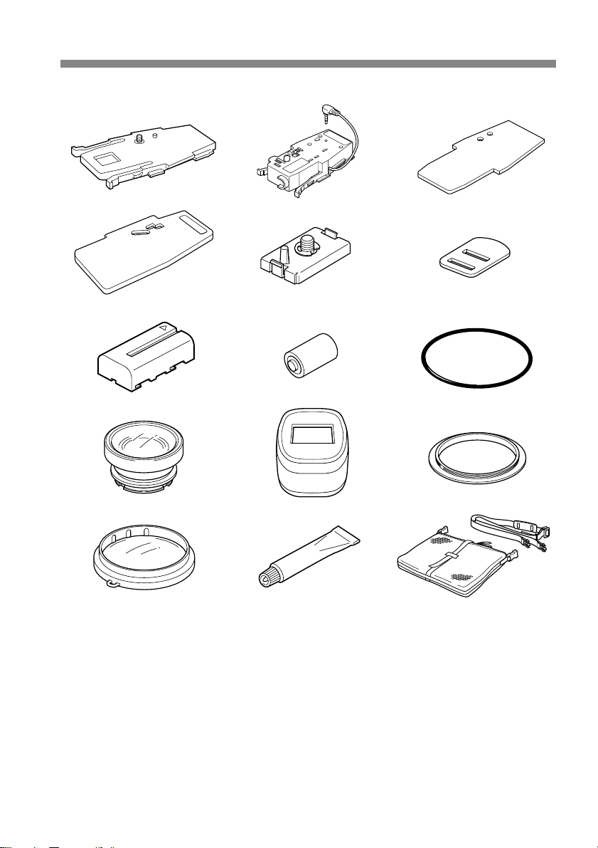
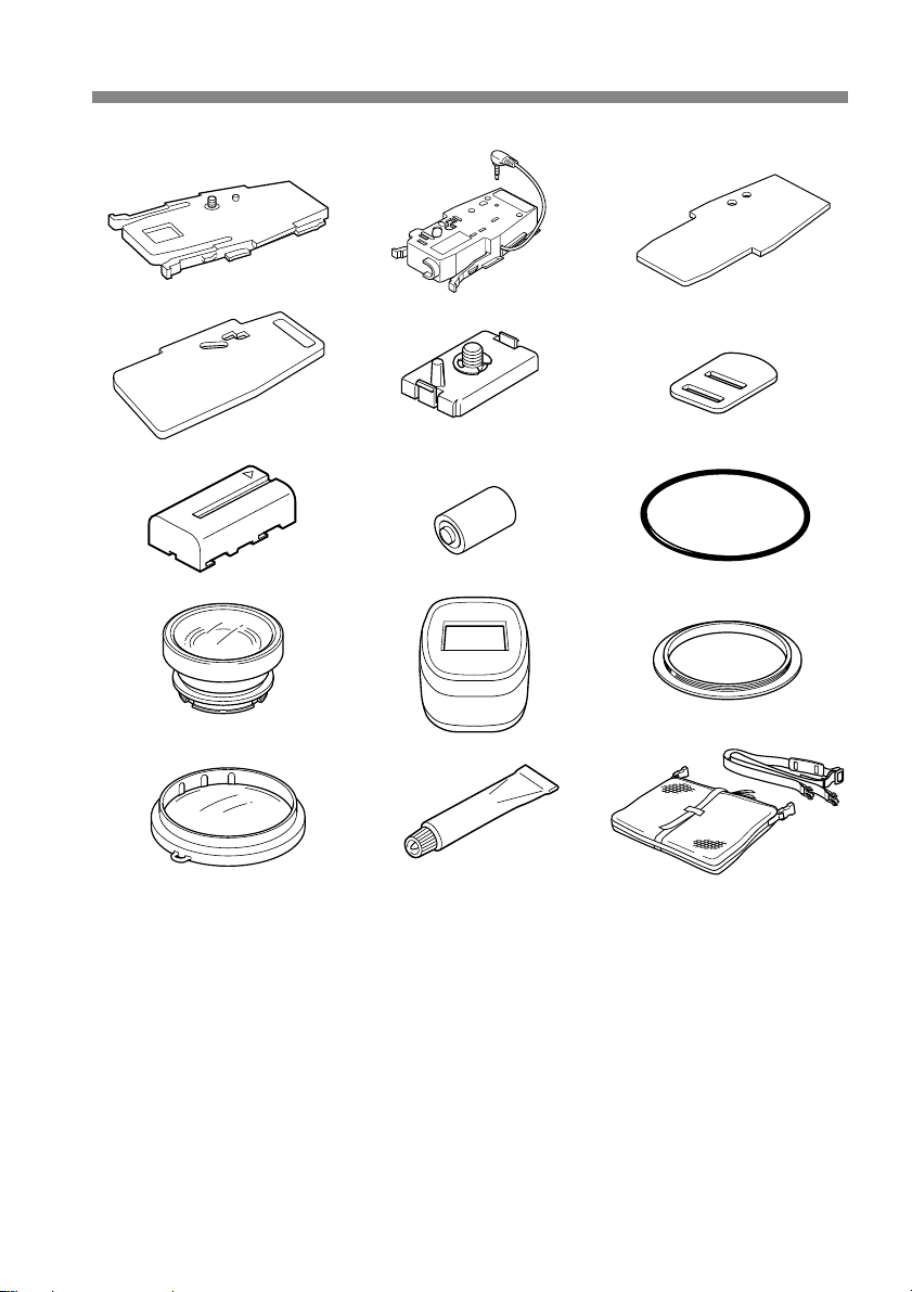
Supplied Accessories
Check that the following accessories are supplied with your marine pack.
123
B
456
789
0qaqs
qd qf qg
1 Camera mounting shoe A (1)
for DCR-TRV7E
2 Camera mounting shoe B (1)
for DCR-TRV6E/TRV8E/TRV9E/
TRV10E/TRV11E/TRV20E/TRV890E/
TRV900E
3 Spacer for camera mounting shoe B
(camera mounting shoe C) (1)
for DCR-TRV8E/TRV10E
4 Camera mounting shoe D (1)
for DCR-TRV6E/TRV11E/TRV20E
5 Screw plate for camera mounting
shoe B and D (2)
6 Screw driver part (1)
Attachment for the camera mounting
shoe B
4-GB
7 NP-F330 battery pack for the LCD
monitor (1)
8 Lithium ion battery CR2 (1)
9 O-ring (1)
0 Underwater wide-conversion lens
(VCL-MK2) (1)
qa Sunshade (1)
qs Reflex prevention ring (2)
Large: ø 37 mm (1)
Small: ø 30 mm (1)
qd Colour filter (VF-MK2) (1)
qf Grease (1)
qg Carrying bag (1) Carrying belt (1)
Battery cushion (1) Strap (3)
Page 5
Preparations
Preparing your camcorder
Before installing your camcorder in the marine pack, prepare the camcorder according
to this chapter. The DCR-TRV20E is the model used for illustration purposes.
Otherwise, the model name is indicated in the illustrations. Any differences in
procedure are clearly indicated in the text, for example, “DCR-TRV20E only.”
The procedure may be different depending on your camcorder type.
For details, please refer to the operating instructions supplied with your camcorder.
1 Remove the lens cap, shoulder strap,
conversion lens, filter or lenshood from
the camcorder.
2 Attach a charged battery pack.
3 Insert a cassette tape.
4 Attach the reflex prevention ring to the lens.
for DCR-TRV7E/TRV9E/TRV20E : ø 37 mm (large)
for DCR-TRV6E/TRV8E/TRV10E/TRV11E : ø 30 mm (small)
for DCR-TRV890E/TRV900E : not necessary
Be sure not too tighten prevention ring.
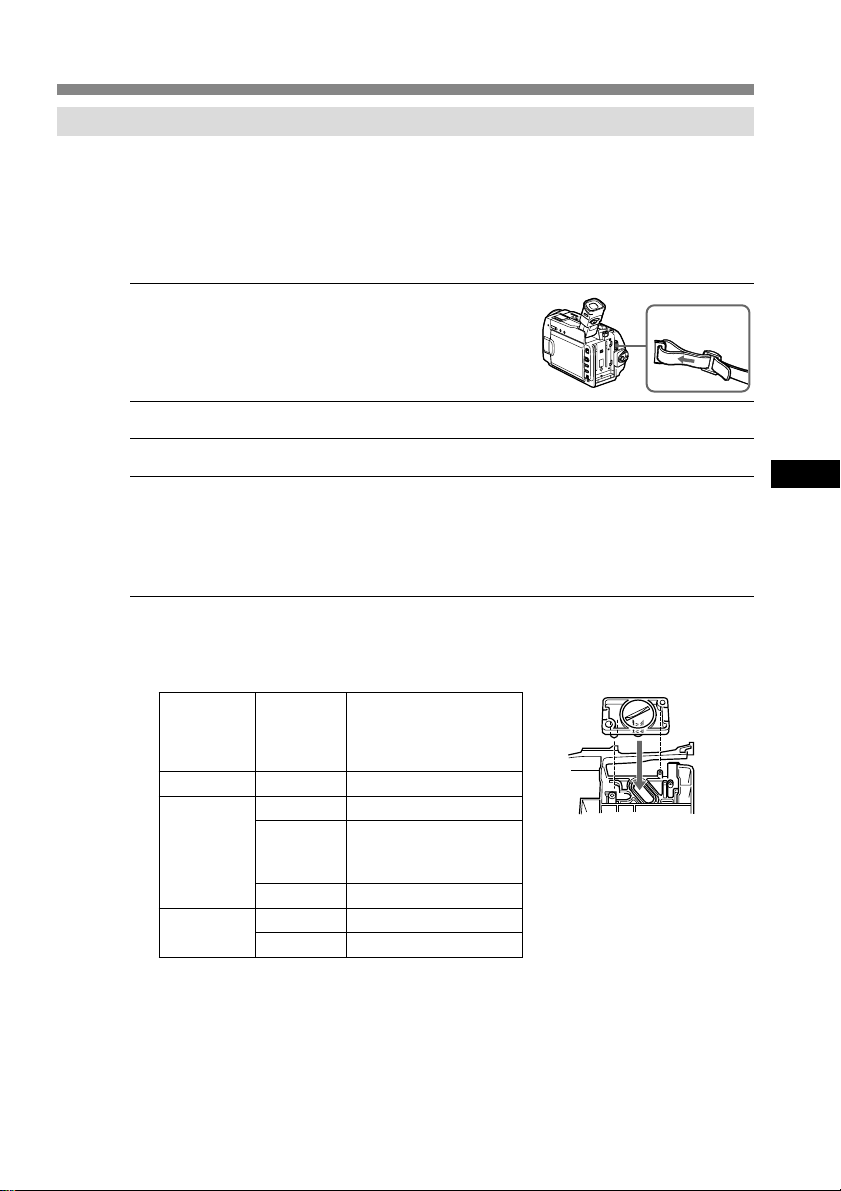
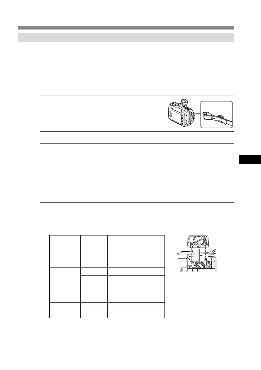
5 Select the camera mounting shoe.
The camera mounting shoe and the installing position of the screw plate differ on
your camcorder. For details, refer to the table below.
Camera
mounting
shoe
A
B
D
Note
For DCR-TRV7E, use the camera mounting shoe A only. Do not use camera
mounting shoe B, D, and the screw plate.
Position
of the
screw
plate
–
1
2
3
1
2
Camcorder
DCR-TRV7E
DCR-TRV9E
DCR-TRV6E/TRV11E/
TRV20E/TRV890E/
TRV900E
DCR-TRV8E/TRV10E
DCR-TRV20E
DCR-TRV6E/TRV11E
1
Installation position
of the screw plate
on the camera
mounting shoe B
GB
continued
5-GB
Page 6
Preparation (continued)
6 Attach the camera mounting shoe.
For DCR-TRV7E
Use camera mounting shoe A.
Fasten the screw of shoe A to the
tripod screw hole of the camcorder
and tighten firmly.
For DCR-TRV9E/TRV890E/TRV900E
Use camera mounting shoe B and
the screw plate.
1 Check the installation position
(1, 2, or 3) of the screw plate for
your camcorder according to the
table on page 5.
2 Attach the screw plate so that
the catch on the reverse side of
shoe B clicks into place.
3 Fasten the screw of the screw
plate to the tripod screw hole of
the camcorder and tighten
firmly.
4 Connect the A/V cable of the
shoe to the camcorder’s
AUDIO/VIDEO jack.
Remove the screw
driver part.
Fasten
tightly.
B
Camera mounting
shoe B
Screw plate
6-GB
Page 7
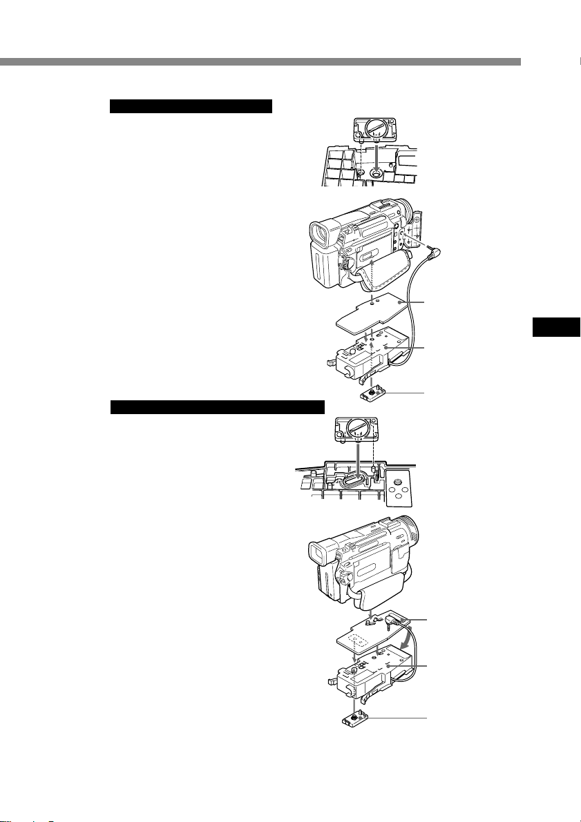
For DCR-TRV8E/TRV10E
Use camera mounting shoe B,
spacer (camera mounting shoe C),
and the screw plate.
1 Attach the spacer to shoe B.
2 Attach the screw plate to
position 3 on shoe B so that the
catch on the reverse side of the
shoe clicks into place.
3 Fasten the screw of the screw
plate to the tripod screw hole of
the camcorder and tighten
firmly.
4 Connect the A/V cable of the
shoe to the camcorder’s
AUDIO/VIDEO jack.
For DCR-TRV6E/TRV11E/TRV20E
Use camera mounting shoe B, and
D, and the screw plate.
1 Attach the screw plate to the
position 1 on shoe D so that the
catch on the reverse side of the
shoe D clicks into place.
2 Fasten the screw of the screw
plate on shoe D to the tripod
screw hole of the camcorder and
tighten firmly.
3 Attach the screw plate to the
position 2 on shoe B.
4 Fasten the screw of the screw
plate on the shoe B to the screw
hole on the shoe D of the
camcorder tightly.
5 Connect the A/V cable of the
shoe to the camcorder’s
AUDIO/VIDEO jack.
Installation
position
of the screw plate
3
on the camera
mounting shoe B
Spacer
(camera mounting
shoe C)
GB
Camera mounting
shoe B
Screw plate
Installation
position
of the screw plate
1
2
of the camera
mounting shoe D
Camera mounting
shoe D
B
Camera mounting
shoe B
Screw plate
Now you are ready to install the camcorder to the marine pack.
Be sure to check that the camera mounting shoe is attached to the camcorder
tightly before you install the camcorder to the marine pack.
continued
7-GB
Page 8
Preparation (continued)
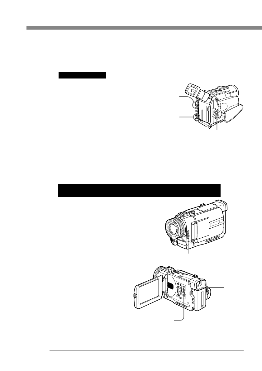
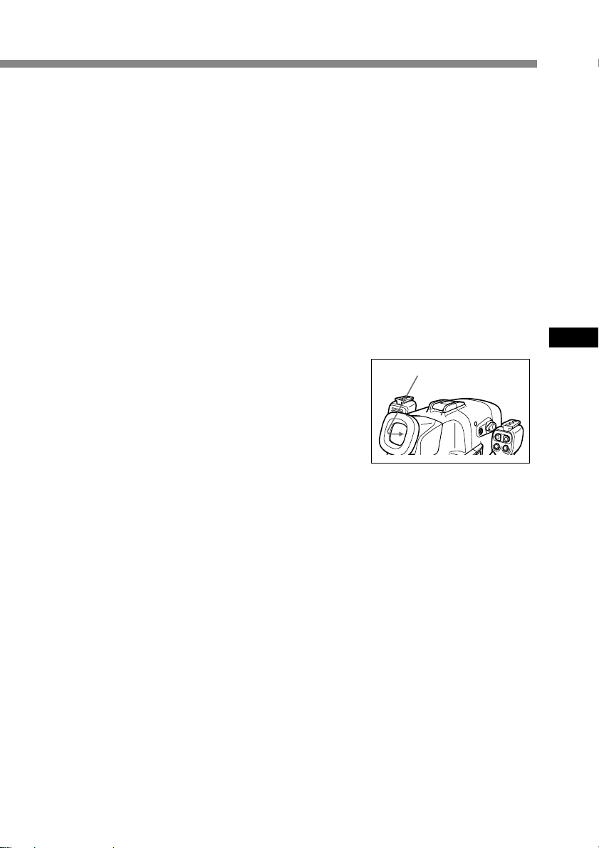
7 Prepare to record.
Before installing the marine pack to the camcorder, prepare the camcorder for
recording.
For DCR-TRV7E
1 Set the POWER switch to
CAMERA.
2 Set the COMMANDER
to ON in the menu system.
3 Cancel the following functions:
BACK LIGHT, Night Shot,
PROGRAM AE, and Picture
Effect.
4 Slide the AUTO LOCK switch
up to AUTO.
5 Select V-OUT/LCD in the
DISPLAY menu and press the
DISPLAY button on your
camcorder before installing it to
the marine pack.
For DCR-TRV6E/TRV8E/TRV9E/TRV10E/TRV11E/TRV20E/
TRV890E/TRV900E
1 Set the POWER switch to
CAMERA.
2 Set the COMMANDER
to ON in the menu system.
3 Cancel the following functions:
BACK LIGHT, Night Shot,
PROGRAM AE, and Picture
Effect.
4 Set the FOCUS switch to AUTO.
5 Select V-OUT/LCD in the
DISPLAY menu and press the
DISPLAY button on your
camcorder before installing the
marine pack.
AUTO LOCK
switch
MENU button
POWER switch
FOCUS switch
POWER
switch
8-GB
MENU button
* If your camcorder has REC lamp switch, set the REC lamp to OFF. By using this
function, the light of the lamp is not reflected in the lens. For details, please refer
to the operating instructions supplied with your camcorder.
Page 9
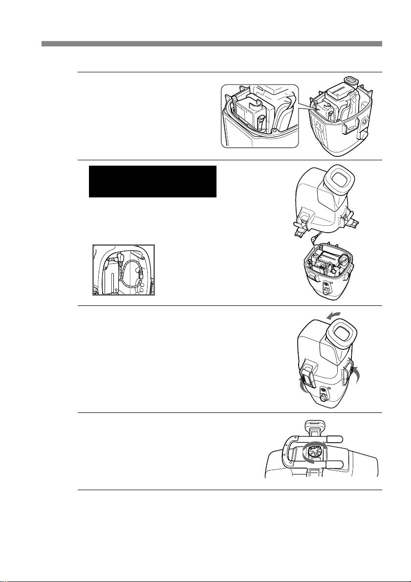
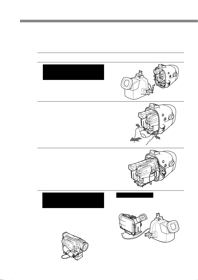
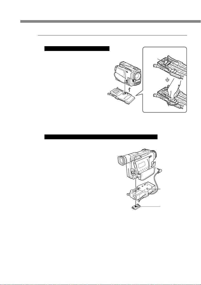
Preparing the marine pack (installing the battery)
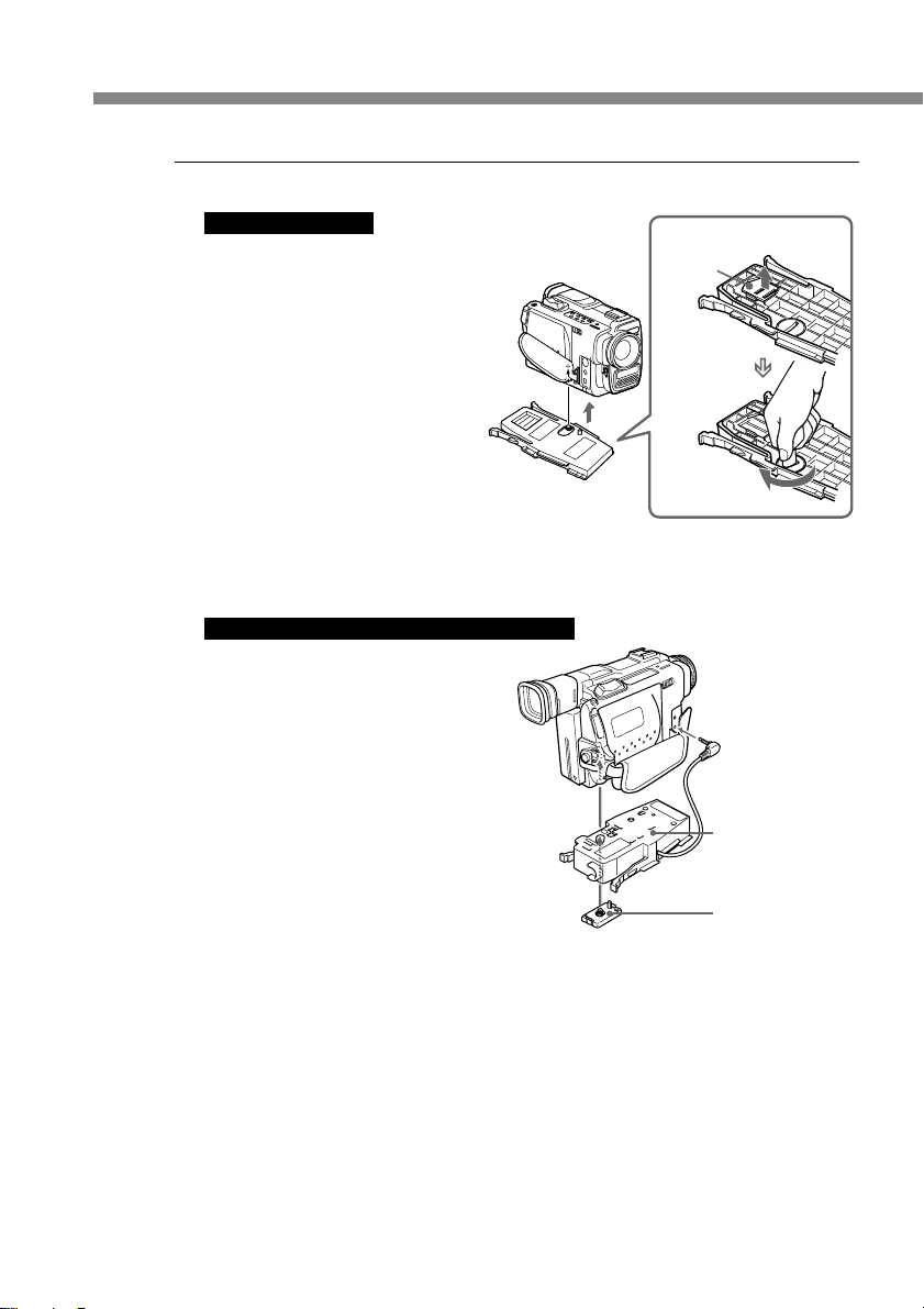
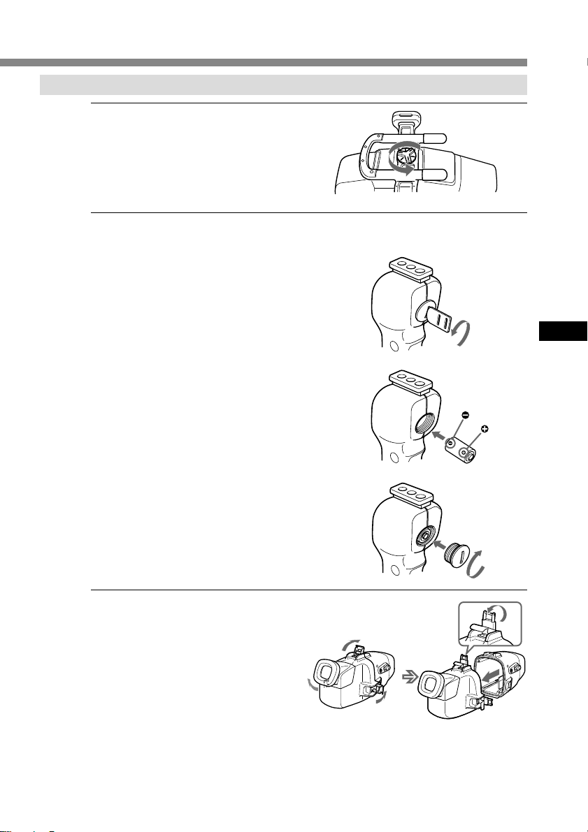
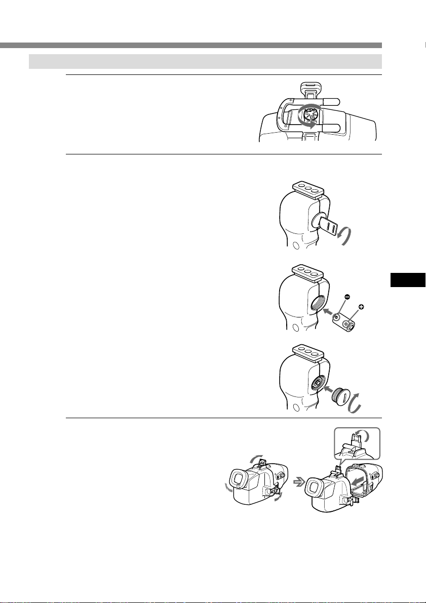
1 Remove the grip.
Undo the screw on the bottom side
of the marine pack.
2 Insert the lithium battery into the grip.
1 Remove the screw with the
supplied screw driver.
2 Insert the supplied lithium
battery (CR2, x 1) with the
polarity positioned correctly as
indicated on the grip.
3 Fasten the screw tightly.
GB
3 Unfasten the 3 latches and open
the marine pack.
If you lift the metal part in the
direction of the finder when the
latches are open, the latches will
stop.
continued
9-GB
Page 10
Preparation (continued)
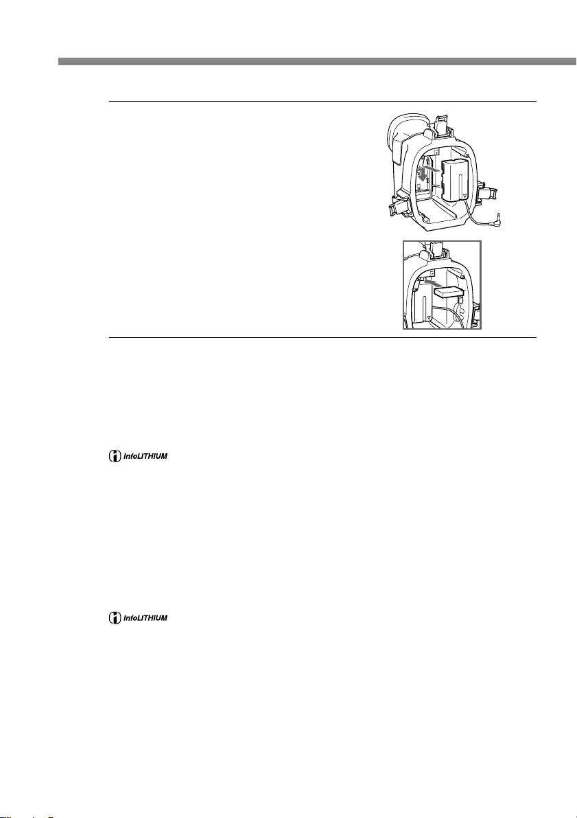
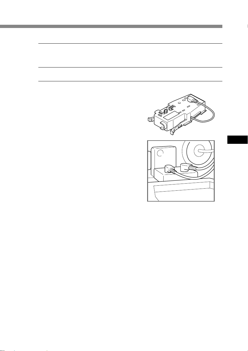
4 Attach the supplied battery pack
NP-F330 for the LCD monitor to
the rear shell. Be sure to charge
the battery pack fully before
attaching.
Note
Firmly insert the supplied battery cushion as shown
to prevent the battery pack from coming loose if it
is dropped or otherwise subjected to impact.
About the supplied battery pack NP-F330
What is an “InfoLITHIUM” battery pack?
The “InfoLITHIUM” is a lithium ion battery pack which can exchange data with
compatible electronic equipment about its battery consumption. Sony recommends that
you use the “InfoLITHIUM” battery pack with electronic equipment having the
* The indication may not be accurate depending on the conditions and environment
• To charge the supplied NP-F330 battery pack, prepare AC adapter/charger that can
charge infolithium L type (not supplied).
• You can use also the infolithium L type and NP-F530/F550 AC adapter/charger (not
supplied).
• The recording time of a fully charged NP-F330 battery pack is approximately 6 hours
(continuous recording). The actual recording time may be less, depending on
conditions of use.
mark.
in which the equipment is used.
“InfoLITHIUM” is a trademark of Sony Corporation.
10-GB
The “InfoLITHIUM” battery pack is recyclable. When the battery is
exhausted and can no longer be recharged, cover the metal parts of the
battery with an isolator such as scotch tape and take it to a battery
recycling shop.
About the LCD monitor
• Images do not appear on the LCD screen unless it is fully connected to your
camcorder.
• The remaining time displayed on the LCD screen refers to remaining time of the
camcorder battery time, not the remaining time of the LCD monitor battery.
• The LCD monitor of the marine pack does not correspond with the “InfoLITHIUM”
battery pack.
Page 11
Installing the camcorder to the marine pack
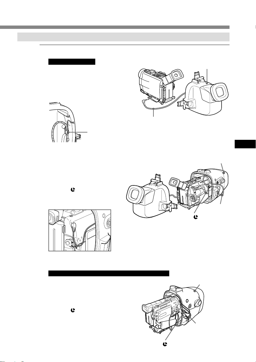
1 Install the camcorder to the marine pack.
For DCR-TRV7E
Connect the monitor plug.
1 Remove the monitor cord hook.
2 Connect the monitor plug to the
AUDIO/VIDEO jack of the
camcorder.
monitor cord hook
Slide through, then pull
outward.
Connect the remote plug and the
microphone plug.
3 Connect the microphone plug to
the MIC jack (plug in power).
4 Connect the remote plug to the
LANC control jack.
Note
To prevent the cords from twisting or slacking,
make sure that these plugs are inserted in the
direction indicated in the illustration.
to the AUDIO/VIDEO
jack
to the LANC
control jack
rear shell
GB
front shell
to the MIC
jack
(plug in
power)
For DCR-TRV9E/TRV10E/TRV20E/TRV900E
Connect the remote plug and the
microphone plug.
1 Connect the microphone plug to
the MIC jack (plug in power).
2 Connect the remote plug to the
LANC control jack.
to the LANC control jack
front shell
to the MIC jack
(plug in power)
continued
11-GB
Page 12
Preparation (continued)
2 Insert the camcorder until the
mounting shoe clicks into place.
3 For DCR-TRV6E/TRV8E/
TRV9E/TRV10E/TRV11E/
TRV20E/TRV890E/TRV900E
Connect the monitor cord to the
jack of camera mounting shoe B.
The cords are placed in the plug
holders of the marine pack at the
factory. Pull the plugs out of the
holders when in use.
12-GB
4 Attach the front shell to the rear
shell. Hold both shells firmly and
fasten the 3 latches securely.
Take care not to pinch the
remote, microphone, and monitor
cords. If this happens water may
leak in.
For details on handling the O-ring,
see page 20.
5 Attach the grip.
Fasten the screw tightly.
Now you have finished the preparations. Be sure to check that the equipment
operates correctly and that there is no water leakage before you dive (see page 16).
Page 13
Recording
Now you are ready for underwater recording.
When you dive with the camcorder, dive slowly, paying attention to the surrounding
environment. Be careful not to strike the marine pack against Rocks or Reef, etc.
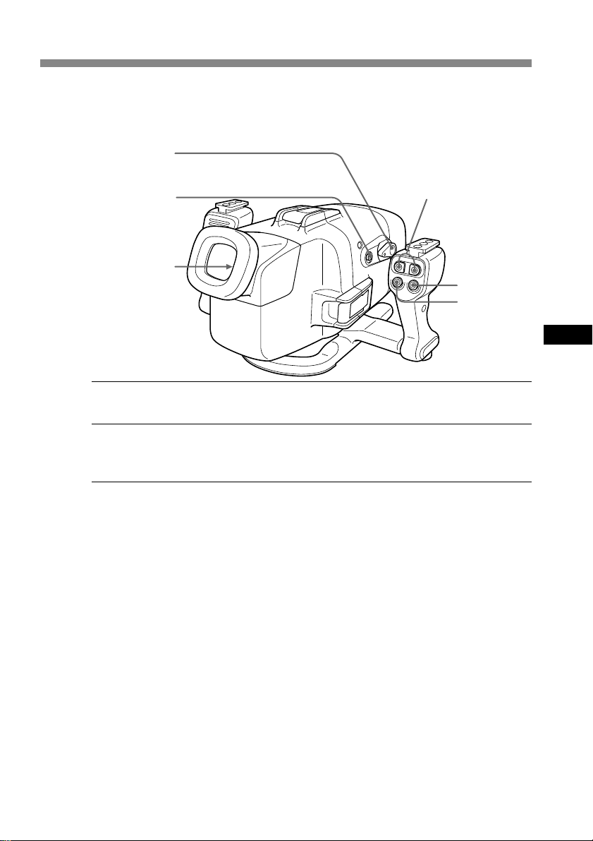
POWER switch
AUTO FOCUS
ON/OFF button
REC lamp (red)
LEAK lamp
(yellow)
ZOOM button
PHOTO button
START/STOP
button
1 Set the POWER switch to ON.
The camcorder turns on and a picture appears on the LCD monitor.
2 Press the START/STOP button to start recording.
The REC lamp (red) lights up during recording.
To stop recording, press the START/STOP button again.
To zoom
Press the ZOOM button.
Press T for telephoto (subject appears closer) and W for wide-angle (subject appears
further away). You cannot change the zooming speed of the camcorder.
Recording a still image on a tape (Tape photo recording)
(DCR-TRV6E/TRV8E/TRV9E/TRV10E/TRV11E/TRV20E/TRV890E/
TRV900E only)
To record a still image, press the PHOTO button. The still image appearing on the LCD
screen is recorded. Note that pressing the PHOTO button lightly does not allow you to
check the recorded image. The memory photo function does not work on the DCRTRV10E/TRV11E/TRV20E/TRV900E models. For more details, refer to the operation
instructions supplied with your camcorder.
GB
To keep a subject in focus
Press the AUTO FOCUS ON/OFF button to set it to OFF. You can still keep the subject
in focus even if fish swim between the camcorder and the subject. Press the AUTO
FOCUS ON/OFF button again to set the camcorder to auto focus mode.
Note
Do not cover the control emitter or detector with your finger as the remote control
signal for operations is transmitted from the grip to the marine pack.
continued
13-GB
Page 14
Recording (continued)
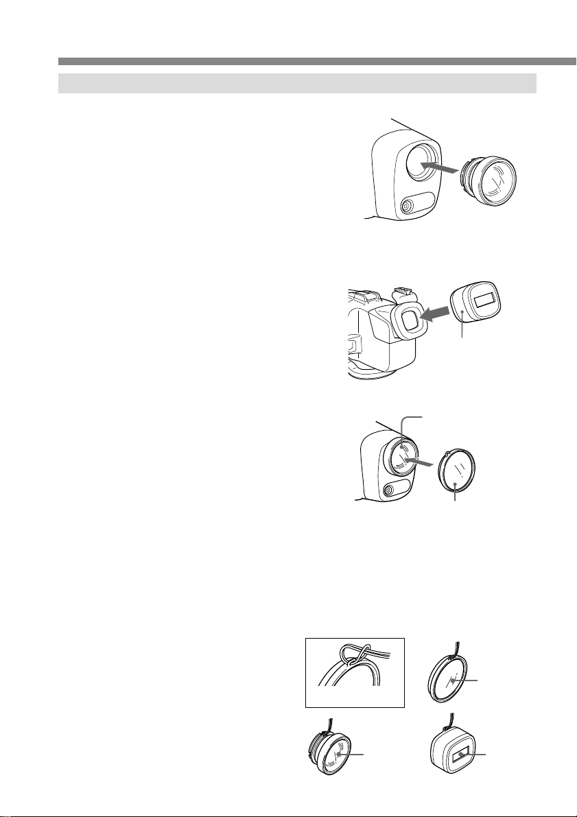
Attaching the supplied accessories
Attaching the supplied wide-conversion lens
As objects appear 1/4 closer and
therefore larger, the wide-conversion
lens is recommended when you want to
take pictures of wide areas. Note
however, that objects will appear
smaller.
Note
This supplied wide-conversion lens is
to be used only underwater.
Using the supplied sunshade
The supplied sunshade reduces glare
from the LCD monitor.
Attaching the supplied colour filter
When using the supplied colour filter,
attach it on top of the wide-conversion
lens.
Water absorbs light, especially red
light, so that objects in deep water are
seen bluish. The colour of objects is
affected by the clarity of the water.
To record in natural colour, use the
supplied colour filter.
Attach the wide-conversion lens until it
fits firmly.
Supplied sunshade
Wide-conversion lens
colour filter
14-GB
You can attach and remove the wide-conversion lens, sunshade, and colour filter
underwater.
If the image on the LCD screen is not clear because of air between these accessories and
the marine pack, reattach them underwater.
Attaching the supplied strap
Attach the strap as the shown.
Attach the supplied straps to prevent
loss of these accessories when
removing them both on land and
underwater.
To attach the strap
Wideconversion
lens
colour filter
Sunshade
Page 15
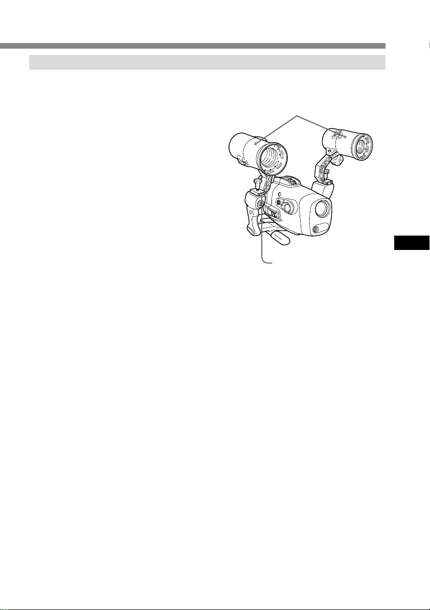
Attaching the optional accessories
Underwater video light
In deep water or under rocks where
direct sunlight does not reach,
recording with underwater video lights
is recommended.
You can attach these video lights to the
video light shoes on the upper part of
both grips.
Underwater video lights such as the
Sony HVL-ML20 (not supplied)
GB
Attachable to the video light
shoes on both sides
15-GB
Page 16

Underwater recording
Before diving
Check that the equipment operates correctly and that there is no water leakage at a
depth of about one meter (3 feet) before you dive deeper.
Take care not to expose the equipment to salty air. Do not drop water on the equipment.
Do not open the marine pack underwater or on the beach. Preparations such as
installing and checking the equipment should be done in a place with low humidity and
no salty air.
Check the following points again before you dive.
s Be sure to fully charge both the battery pack of the marine pack and the
camcorder.
• We recommend you use battery packs with a large capacity and prepare a spare
battery.
s Be sure that a video tape has enough left.
s Check that there are no scratches or cracks on the O-ring.
s Make sure there is no dust, sand, or hair between the front shell and the rear shell.
s Be sure that the lithium battery has enough power.
• The Flash lamp lights up if the
remaining battery capacity is
enough. Check this indicator as
a criterion. If the flash lamp does
not light, exchange for a new
one. We suggest that you
prepare spare ones.
Battery
check
indicator
Right
grip
16-GB
Conditions of underwater recording
Recording underwater is different from recording on land because it is affected by
the clarity, depth of the water, and the light conditions. The following are hints
for good recording underwater.
Best time for recording
The best recording time is from 10:00 a.m. to 2:00 p.m. When the sun is at its highest,
optimum results can be obtained.
To record is in dark places as the sun does not reach or at night, use a powerful
underwater video light.
Page 17
Subject size underwater
Since the refractive index underwater is higher than that in air, objects appear 1/4
closer, and therefore larger. This phenomenon affects the lens on the camcorder as well
as human the eye. Using the supplied wide-conversion lens is recommended.
Operate the camera with slow and stable motions
When recording, keep your body stable.
An unstable shot will be magnified on the TV screen.
Move the camcorder as slowly as possible. Since most of the objects underwater move,
you can record a good shot without moving the camcorder too much.
Note on recording underwater
Be sure to follow the safety rules for diving, such as diving period and depth.
Water leakage
The marine pack is designed to be
waterproof, however if water happens
to leak in ,the LEAK lamp (yellow)
flashes.
In such a case, remove the marine pack
from the water as soon as possible,
keeping it horizontal. Be sure to surface
following the safety rules for diving.
Dry the marine pack with a soft cloth
and then open it.
To switch off the lamp, disconnect the remote control cable.
Check the cause of the leak.
If the camcorder is wet, take it to the nearest Sony dealer immediately.
We recommend you purchase property damage insurance for underwater materials in
case of emergency.
LEAK lamp (yellow)
After using
• After recording in the sea, submerge the marine pack in tap water or fresh water for
about 30-60 minutes before undoing the latches to completely remove any salt from
the marine pack unit, filter, and wide-conversion lens.
• When your camcorder is to be used near the sea for a long time, we recommend that
it be checked periodically by a Sony dealer.
GB
17-GB
Page 18
Removing the camcorder
Before opening the marine pack, rinse it with fresh water and dry with a soft cloth.
When you open the marine pack, make sure you are dry. And take care that no water
drips from your wet suit.
1 Remove the grip.
2 For DCR-TRV6E/TRV8E/
TRV9E/TRV10E/TRV11E/
TRV20E/TRV890E/TRV900E
Unfasten 3 latches and open the
marine pack.
Disconnect the monitor cord from
the camera mounting shoe B.
3 Take the camcorder out of the
front shell.
Hold the camera mounting shoe by
the knobs and extract the
camcorder.
When you open the marine pack,
do not pull the monitor plug cord
by force.
18-GB
4 Disconnect the remote plug and
the microphone plug.
5 For DCR-TRV6E/TRV8E/
TRV9E/TRV10E/TRV11E/
TRV20E/TRV890E/TRV900E
Disconnect the A/V connecting
cable of camera mounting shoe B
from the AUDIO/VIDEO jack.
For DCR-TRV7E
Disconnect the monitor plug from
the AUDIO/VIDEO jack.
Page 19
6 Remove the camera mounting shoe with the screw driver.
B
Undo the screw of the screw plate and remove the camera mounting shoe from the
camcorder.
7 Remove the battery pack for the LCD monitor.
After using the marine pack
• Insert the A/V connecting cable plug
to the plug holder of the camera
mounting shoe B.
• Insert the remote and microphone
plugs to the plug holder inside of the
front shell.
GB
19-GB
Page 20

Note on the O-ring
The O-ring assures the waterproof function of the marine pack. To maintain
waterproof integrity, use it correctly.
Incorrect handling may cause water to
leak in.
Check the O-ring
Before using the marine pack each time, check that there are no scratches or cracks on
the O-ring and prevent dust from collection on it as it could allow water to leak in.
• Remove the O-ring from the groove with your finger. Do not use a metal tool or a
tool with a sharp point.
• Put the O-ring in the groove evenly. Never twist it.
• Check that there are no cracks or dust on the O-ring, then coat it slightly with the
supplied grease using your finger. This will prevent wear.
• While applying the grease, recheck for cracks or dust. Never use cloth or paper to
apply grease because the fibers may cling.
If you run out of silicone grease (2-115-921-01) you can purchase it from your
nearest Sony Service Center.
Remove any dust, sand, or hair from the O-ring
Make sure there is no dust, sand, or hair on the O-ring, in the groove, or on the surface
of the marine pack where the O-ring touches. If there is, clean it completely, or the Oring and the surface of the marine pack may be damaged and water may leak in.
O-ring
20-GB
Do not pinch the O-ring with the marine pack
When joining the front and rear shells, take care not to pinch the O-ring between the
front and rear shells. If this happens, not only will the O-ring be damaged, but water
may leak in.
Useful life of the O-ring
Depending upon the maintenance and the length of use, we recommend changing the
O-ring every one or two years.
The O-ring (3-977-362-01) can be replaced at your nearest Sony Service Center.
When you store the O-ring
Store a reserve O-ring in its package in a cool dry place. Do not store in very hot, cold,
or humid place. Be careful not to crimp it or to place any heavy weight on it.
Page 21
Caution on handling
After using
The metal parts will rust and the movement of the operation switches will be impaired
if you leave salt water on the marine pack. If sea water enters through scratches in the
coating, the salt can corrode the metal parts of the marine pack unit and cause the
coating to peel off. After recording in the sea, submerge the marine pack in tap water or
fresh water for about 30 minutes before undoing the buckles to completely remove any
salt from the marine pack unit, filter, and wide-conversion lens.
After washing, wipe any water from the inside of the marine pack and the loaded video
camcorder with a soft dry cloth.
* Always follow the above precautions when you use the marine pack.
When you open the marine pack or exchange the battery pack of the grip, take care that
no water drips from your wet suit or hair.
Do not leave the marine pack under direct sunlight for a long period of time, otherwise
the temperature in the marine pack may rise and the equipment inside may be
damaged. If you cannot avoid leaving the marine pack under direct sunlight, be sure to
cover the marine pack with a towel or other protection.
When you store the marine pack
Coat the O-ring slightly with the supplied grease, and put it in the groove correctly. Join
the front and rear shells then put it in a cool and dry place without fastening the
buckles.
Avoid storing the marine pack in a very hot, cold, or humid place, or together with
naphthalene or camphor, as these conditions might damage the unit.
On transportation
When transporting the marine pack, be sure to remove your camcorder from it.
Otherwise this might damage the unit.
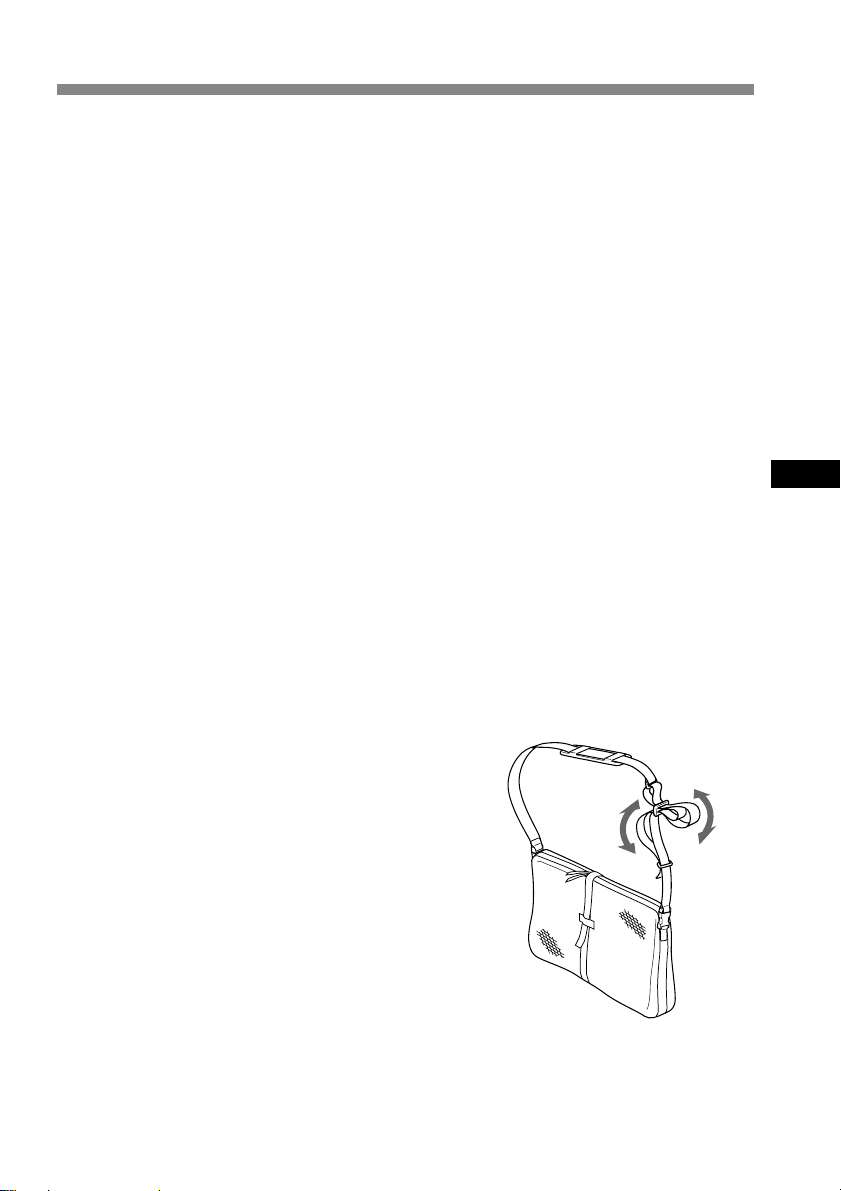
Note
When you use the supplied carrying
bag, attach the supplied carrying belt
and adjust the length of the belt.
Avoid rough handling or a shock. We
recommend covering the marine pack
with a towel or other protection.
GB
21-GB
Page 22
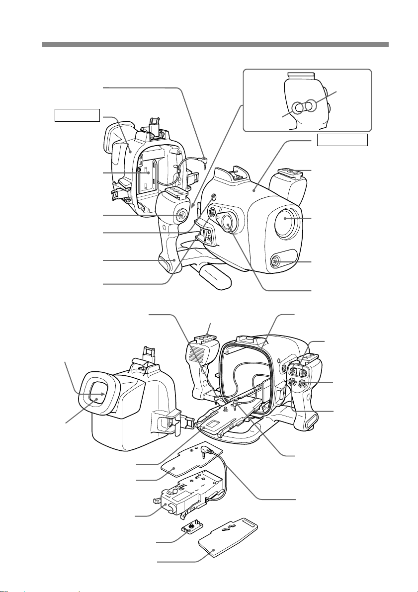
Identifying parts and controls
Monitor plug
Rear shell
NP-F330
compartment
Dry batteries
compartment
Remote control
detector
Grip
AUTO FOCUS
ON/OFF button
Remote plug (blue)
REC lamp (red)
LEAK lamp (yellow)
Guide rail
Remote
control
transmitter
Battery
check
indicator
Front shell
Video light shoe
Front glass
Underwater
microphone
(monaural)
POWER switch
O-ring
ZOOM buttons
LCD
monitor
Camera mounting shoe A
Spacer for camera
mounting shoe B
(camera mounting
shoe C)
Camera mounting shoe B
Camera mounting shoe D
22-GB
PHOTO button
START/STOP
button
Microphone plug
B
A/V connecting cable
Screw plate
Page 23

Specifications
Material
Aluminum alloy, glass, plastic (ABS, PC)
Waterproofing
O-ring, 3 latches
Usable depth
Up to 75 meters (246 feet)
Underwater microphone
Condenser microphone (monaural)
Controllable function
Power on/off, recording start/stop, auto focus on/off, power zooming,
tape photo recording (DCR-TRV6E/TRV8E/TRV9E/TRV10E/TRV11E/TRV20E/TRV890E/
TRV900E only)
Dimensions
Approx. 312 x 212 x 318 mm (w/h/d)
(12 3/8 x 8 3/8 x 12 5/8 in.)
Mass
Approx. 4.4 kg (9 lb 11 oz) (the unit only)
Supplied accessories
Camera mounting shoe A, B, D (1 each)
Spacer for camera mounting shoe B (Camera mounting shoe C) (1)
Screw plate (2)
Screw driver part (1)
Wide-conversion lens (1)
Colour filter (1)
NP-F330 battery pack for the monitor (1)
Lithium battery CR2 (1)
Grease (1)
O-ring (1)
Sunshade (1)
Reflex prevention ring (2)
Strap (3)
Battery cushion (1)
Carrying bag (1)
Carrying belt (1)
Operating instructions (1)
Warranty (1)
Recommended accessory
Underwater video light HVL-ML20
GB
Design and specifications are subject to change without notice.
23-GB
Page 24

Page 25

Table des matières
Fonctions et précautions ............................. 3
Accessoires fournis ...................................... 4
Préparatifs..................................................... 5
Préparation du caméscope .................. 5
Préparation du caisson étanche
(installation de la pile) .......................... 9
Installation du caméscope dans le
caisson étanche .................................... 11
Enregistrement ........................................... 13
Fixation des accessoires fournis ........ 14
Fixation des accessoires en option.... 15
Fonctions et précautions
• Le modèle MPK-DVF3 peut être utilisé avec les caméscopes Sony Handycam Vision
DCR-TRV6E/TRV7E/TRV8E/TRV9E/TRV10E/TRV11E/TRV20E/TRV890E/
TRV900E.
• Il est possible d’enregistrer à des profondeurs allant jusqu’à 75 mètres.
• Les opérations suivantes peuvent être effectuées sous l’eau :
– Mise sous/hors tension de l’appareil
– Activation/désactivation de la mise au point automatique
– Début/arrêt de l’enregistrement
– Enregistrement d’une photo (DCR-TRV6E/TRV8E/TRV9E/TRV10E/TRV11E/
TRV20E/TRV890E/TRV900E uniquement)
– Fonction de zoom électrique
– Contrôle de l’afficheur à cristaux liquides
Enregistrement sous-marin ...................... 16
Fuite d’eau ........................................... 17
Retrait du caméscope ................................ 18
Remarque concernant le joint torique .... 20
Précaution d’emploi .................................. 21
Identification des pièces et des
commandes .................................................. 22
Spécifications.............................................. 23
™
FR
Sony ne peut être tenu responsable des dégâts causés au caméscope, aux piles, ni
aux autres équipements installés dans le caisson étanche, ni de la perte des
données pré-enregistrées en cas de fuite due à une mauvaise manipulation.
Ce symbole indique que ce produit est un accessoire vidéo Sony
authentique. Pour tout achat d’un produit vidéo Sony, Sony vous
recommande d’acheter des accessoires portant la marque
“GENUINE VIDEO ACCESSORIES”.
3-FR
Page 26
Accessoires fournis
Vérifiez que vous avez reçu les accessoires suivants avec le caisson étanche.
123
B
45
7
0qa
qd qf
1 Support de montage du caméscope A (1)
pour le modèle DCR-TRV7E
2 Support de montage du caméscope B (1)
pour les modèles DCR-TRV6E/TRV8E/
TRV9E/TRV10E/TRV11E/TRV20E/
TRV890E/TRV900E
3 Espaceur pour support de montage du
caméscope B (support de montage du
caméscope C) (1)
pour les modèles DCR-TRV8E/TRV10E
4 Support de montage du caméscope D (1)
pour les modèles DCR-TRV6E/
TRV11E/TRV20E
5 Plaque à vis pour les supports de
montage de caméscope B et D (2)
6 Tournevis (1)
4-FR
Fixation pour le support de montage du
caméscope B
8
6
9
qs
qg
7 Bloc-pile NP-F330 du moniteur à
cristaux liquides (1)
8 Pile au lithium CR2 (1)
9 Joint torique (1)
0 Objectif grand-angulaire (VCL-MK2) (1)
qa Parasoleil (1)
qs Bague de prévention Reflex (2)
Grande bague : ø 37 mm (1)
Petite bague : ø 30 mm (1)
qd Filtre couleur (VF-MK2) (1)
qf Graisse (1)
qg Sac (1) Sangle (1)
Tampon de protection de la pile (1)
Bandoulière (3)
Page 27
Préparatifs
Préparation du caméscope
Avant d’installer votre caméscope dans le caisson étanche, effectuez les préparatifs
indiqués dans ce chapitre. Nous utilisons le DCR-TRV20E comme modèle d’illustration.
Sinon, le nom du modèle utilisé est indiqué dans les illustrations. La procédure peut
varier en fonction de votre caméscope : dans ce cas, une mention du type “DCR-
TRV20E uniquement” est ajoutée.
Pour obtenir davantage d’informations, reportez-vous au mode d’emploi fourni avec
votre caméscope.
1 Retirez le bouchon de l’objectif, la
bandoulière, l’objectif grandangulaire, le filtre ou le parasoleil
du caméscope.
2 Insérez un bloc-pile chargé.
3 Insérez une cassette.
4 Fixez la bague de prévention Reflex sur l’objectif.
pour les modèles DCR-TRV7E/TRV9E/TRV20E : ø 37 mm
pour les modèles DCR-TRV6E/TRV8E/TRV10E/TRV11E : ø 30 mm
pour les modèles DCR-TRV890E/TRV900E : non nécessaire
Assurez-vous de ne pas trop visser la bague de prévention.
(grande bague)
(petite bague)
US
FR
5 Sélectionnez le support de montage du caméscope.
Le support de montage et la position d’installation de la plaque à vis diffèrent
selon le type de caméscope utilisé. Pour plus d’informations, reportez-vous au
tableau ci-dessous.
Support
de montage
du
caméscope
A
B
D
Remarque
Avec le modèle DCR-TRV7E, n’utilisez que le support de montage A. N’utilisez pas
les supports de montage B, D ni la plaque à vis.
Position
de la
plaque
à vis
–
1
2
3
1
2
Caméscope
DCR-TRV7E
DCR-TRV9E
DCR-TRV6E/TRV11E/
TRV20E/TRV890E/
TRV900E
DCR-TRV8E/TRV10E
DCR-TRV20E
DCR-TRV6E/TRV11E
1
Position d’installation
de la plaque à vis sur le
support de montage du
caméscope B
suite
5-FR
Page 28
Préparatifs (suite)
6 Fixez le support de montage du caméscope.
Pour le modèle DCR-TRV7E
Utilisez le support de montage A.
Vissez fermement la vis du support
A dans le trou de la vis du trépied
du caméscope.
Enlevez
le tournevis.
Vissez
fermement.
Pour les modèles DCR-TRV9E/TRV890E/TRV900E
Utilisez le support de montage B et
la plaque à vis.
1 Vérifiez la position d’installation
(1, 2 ou 3) de la plaque à vis de
votre caméscope en vous
reportant au tableau de la page
5.
2 Attachez la plaque à vis de telle
sorte que l’ergot situé sur
l’envers du support B
s’encliquète correctement.
3 Vissez fermement la vis de la
plaque à vis dans le trou de la
vis du trépied du caméscope.
4 Connectez le câble audio-visuel
(A/V) du support à la prise
AUDIO/VIDÉO du caméscope.
B
Support de
montage du
caméscope B
Plaque à vis
6-FR
Page 29

Pour le modèle DCR-TRV8E/TRV10E
Utilisez le support de montage B,
l’espaceur (support de montage C),
et la plaque à vis.
1 Fixez l’espaceur au support B.
3
2 Fixez la plaque à vis au support
B en position 3 de telle sorte que
l’ergot situé sur l’envers du
support s’encliquète
correctement.
3 Vissez fermement la vis de la
plaque à vis dans le trou de la
vis du trépied du caméscope.
4 Connectez le câble audio-visuel
(A/V) du support à la prise
AUDIO/VIDÉO du caméscope.
Pour le modèle DCR-TRV6E/TRV11E/TRV20E
Utilisez les supports de montage B
et D et la plaque à vis.
1 Fixez la plaque à vis au support
D en position 1 de telle sorte que
l’ergot situé sur l’envers du
support D s’encliquète
correctement.
2 Vissez fermement la vis de la
plaque à vis sur le support D
dans le trou de la vis du trépied
du caméscope.
3 Fixez la plaque à vis au support
B, en position 2.
4 Vissez fermement la vis de la
plaque à vis sur le support B
dans le trou de la vis du support
D du caméscope.
5 Connectez le câble audio-visuel
(A/V) du support à la prise
AUDIO/VIDÉO du caméscope.
1
2
B
Position
d’installation de la
plaque à vis sur le
support de
montage du
caméscope B
Espaceur
(support de
montage C)
Support de
montage du
caméscope B
Plaque à vis
Position
d’installation de la
plaque à vis sur le
support de
montage du
caméscope D
Support de
montage du
caméscope D
Support de
montage du
caméscope B
US
FR
Plaque à vis
Vous êtes maintenant prêt à installer le caméscope dans le caisson étanche.
Vérifiez que le support de montage est solidement fixé au caméscope avant
d’installer ce dernier dans le caisson étanche.
suite
7-FR
Page 30

Préparatifs (suite)
7 Préparation à l’enregistrement
Avant de l’installer dans le caisson étanche, préparez le caméscope à
l’enregistrement.
Pour le modèle DCR-TRV7E
1 Placez POWER (Bouton de mise
sous tension) sur CAMERA
(Appareil).
2 Dans le menu système,
définissez COMMANDER sur
ON (Marche).
3 Annulez les fonctions suivantes :
BACK LIGHT (Lumière arrière),
Night Shot (Cliché nocturne),
PROGRAM AE (Programme
AE) et Picture Effect (Effet
image).
4 Mettez le sélecteur AUTO LOCK (Verrouillage AUTO) sur AUTO.
5 Sélectionnez V-OUT/LCD dans le menu DISPLAY (Affichage) et appuyez sur le
bouton DISPLAY de votre caméscope avant de l’installer dans le caisson
étanche.
Pour les modèles DCR-TRV6E/TRV8E/TRV9E/TRV10E/TRV11E/
TRV20E/TRV890E/TRV900E
1 Placez POWER (Bouton de mise
sous tension) sur CAMERA
(Appareil).
2 Dans le menu système,
définissez COMMANDER sur
ON (Marche).
3 Annulez les fonctions suivantes :
BACK LIGHT (Lumière arrière),
Night Shot (Cliché de nuit),
PROGRAM AE (Programme
AE) et Picture Effect (Effet
image).
4 Placez le sélecteur FOCUS (Mise
au point) sur AUTO.
5 Sélectionnez V-OUT/LCD dans
le menu DISPLAY (Affichage) et
appuyez sur le bouton DISPLAY
de votre caméscope avant de
l’installer dans le caisson
étanche.
* Si votre caméscope comporte un témoin lumineux REC (Enregistrement), réglez
le sur OFF. Grâce à cette fonction, la lumière de la lampe n'est pas reflétée dans
la lentille. Pour obtenir davantage d’informations, reportez-vous au mode
d’emploi fourni avec votre caméscope.
Sélecteur
AUTO LOCK
(Verrouillage
AUTO)
Bouton
MENU
Sélecteur FOCUS
Bouton MENU
POWER (Bouton de
mise sous tension)
POWER
(Bouton de
mise sous
tension)
8-FR
Page 31

Préparation du caisson étanche (installation de la pile)
1 Retirez la poignée.
Dévissez la vis située en dessous du
caisson étanche.
2 Insérez la pile au lithium dans la poignée.
1 Retirez la vis en vous servant du
tournevis fourni.
2 Insérez la pile au lithium (CR2, x 1)
livrée avec l’appareil en respectant
la polarité indiquée dans la poignée.
3 Vissez fermement.
3 Défaites les 3 loquets et ouvrez le
caisson étanche.
Si vous levez la partie métallique
dans la direction du viseur lorsque
les loquets sont défaits, ceux-ci se
bloquent.
US
FR
suite
9-FR
Page 32

Préparatifs (suite)
4 Insérez le bloc-pile NP-F330
fourni pour le moniteur à cristaux
liquides dans le boîtier arrière.
Assurez-vous auparavant que le
bloc-pile est entièrement chargé.
Remarque
Introduisez fermement le tampon de protection de
la pile fourni avec l’appareil pour empêcher le blocpile de se détacher en cas de chute du caisson ou de
tout autre impact.
À propos du bloc-pile NP-F330 fourni
Qu’est-ce qu’un bloc-pile “InfoLITHIUM” ?
Une batterie “InfoLITHIUM” est une batterie au lithium-ion pouvant échanger des
données sur la consommation de la batterie avec des appareils électroniques
compatibles. Sony recommande l'utilisation de la batterie “InfoLITHIUM” avec les
équipements électroniques marqués .
* Il se peut que l’indication fournie ne soit pas précise selon les conditions et
l’environnement d’utilisation de l’appareil.
“InfoLITHIUM” est un marque déposée de Sony Corporation.
• Pour recharger le bloc-pile NP-F330 fourni, utilisez un adaptateur/chargeur CA
pouvant recharger des piles du type infolithium L (non fournies).
• Vous pouvez également utiliser l'adaptateur/chargeur du type infolithium L et le
chargeur/adaptateur NP-F530/F550 (non fournies).
• La durée d’enregistrement d’un bloc-pile NP-F330 entièrement chargé est d’environ 6
heures (enregistrement continu). La durée d’enregistrement réelle peut être inférieure
selon les conditions d’utilisation.
10-FR
Le bloc-pile “InfoLITHIUM” est recyclable. Lorsque la pile est usée et
qu'elle ne peut plus être rechargée, couvrez les parties métalliques avec
un isolant tel qu'un ruban adhésif, et portez-la à un magasin qui recycle
les piles.
À propos du moniteur à cristaux liquides
• Les images n’apparaissent sur l’afficheur à cristaux liquides que lorsqu’il est
entièrement relié à votre caméscope.
• La durée restante affichée sur l’afficheur à cristaux liquides concerne la pile du
caméscope, et non pas celle du moniteur.
• Le moniteur à cristaux liquides du caisson étanche ne correspond pas au bloc-pile
“InfoLITHIUM”.
Page 33

Installation du caméscope dans le caisson étanche
1 Installez le caméscope dans le caisson étanche.
Pour le modèle DCR-TRV7E
Connectez la prise du moniteur.
1 Enlevez la fixation du cordon du
moniteur.
2 Connectez la prise du moniteur
à la prise AUDIO/VIDÉO du
caméscope.
fixation du cordon du moniteur
Faire glisser, puis tirer vers l’extérieur.
Connectez la prise de
télécommande et la prise du
microphone.
3 Connectez la prise du micro à la
prise MIC (branchement).
4 Connectez la prise de
télécommande à la prise de
contrôle LANC .
Remarque
Pour éviter que le cordon ne s’enroule ou ne soit
trop lâche, assurez-vous que ces prises sont
insérées dans le sens indiqué dans l’illustration.
boîtier arrière
à la prise AUDIO/VIDÉO
boîtier avant
à la prise
à la prise
de contrôle
LANC
MIC
(branchement)
US
FR
Pour les modèles DCR-TRV9E/TRV10E/TRV20E/TRV900E
Connectez la prise de
télécommande et la prise du
microphone.
1 Connectez la prise du micro à la
prise MIC (branchement).
2 Connectez la prise de
télécommande à la prise de
contrôle LANC .
à la prise de contrôle LANC
boîtier avant
à la prise MIC
(branchement)
suite
11-FR
Page 34

Préparatifs (suite)
2 Insérez le caméscope jusqu’à ce
que le support de montage
s’encliquète.
3 Pour les modèles
DCR-TRV6E/TRV8E/ TRV9E/
TRV10E/TRV11E/TRV20E/
TRV890E/TRV900E
Connectez le cordon du moniteur
à la prise du support de montage
du caméscope B.
Les cordons sont placés dans les
supports de prise du caisson
étanche à l’usine. Retirez les
prises de leurs supports lorsque
vous utilisez l’appareil.
12-FR
4 Attachez le boîtier avant au
boîtier arrière. Maintenez
fermement les deux boîtiers et
verrouillez solidement les 3
loquets.
Veillez à ne pas pincer les
cordons de la télécommande, du
micro et du moniteur. Sinon,
l’eau risque de s’infiltrer dans
l’appareil.
Pour obtenir davantage
d’informations sur la manipulation
du joint torique, reportez-vous à la
page 20.
5 Fixez la poignée.
Vissez fermement.
Vous en avez maintenant fini avec les préparatifs. Vérifiez que l’équipement fonctionne
correctement et que l’eau ne s’y infiltre pas avant de plonger (voir page 16).
Page 35

Enregistrement
Vous êtes maintenant prêt à enregistrer sous l’eau.
Lorsque vous plongez avec le caméscope, descendez doucement, en prêtant attention à ce qui
vous entoure. Veillez à ne pas cogner le caisson étanche contre des rochers ou des récifs.
POWER (Bouton de
mise sous tension)
Bouton AUTO FOCUS
ON/OFF (Marche/Arrêt)
Témoin REC
(Enregistrement)
(rouge)
Témoin LEAK
(Fruite) (jaune)
Bouton ZOOM
Bouton PHOTO
Bouton
START/STOP
1 Placez le bouton de mise sous tension POWER sur ON (Marche).
Le caméscope se met en marche et une image apparaît sur le moniteur à
cristaux liquides.
2 Appuyez sur le bouton START/STOP (Début/Fin) pour commencer
l’enregistrement.
Le témoin rouge REC (Enregistrement) s’allume pendant toute la durée de
l’enregistrement. Pour arrêter l’enregistrement, appuyez de nouveau sur le bouton
START/STOP (Début/Fin).
Pour faire un zoom
Appuyez sur le bouton ZOOM.
Appuyez sur T pour passer en mode Téléphoto (le sujet semble plus proche) et sur W
pour passer en mode Grand-angulaire (le sujet semble plus éloigné). Vous ne pouvez
pas modifier la vitesse de zoom du caméscope.
Enregistrement d’une image fixe sur une bande (enregistrement
photo sur bande) (DCR-TRV6E/TRV8E/TRV9E/TRV10E/TRV11E/TRV20E/
TRV890E/TRV900E uniquement)
Pour enregistrer une image fixe, appuyez sur le bouton PHOTO. L’image fixe apparaissant
sur l’afficheur est enregistrée. Notez que le fait d’appuyer légèrement sur le bouton PHOTO
ne vous permet pas de vérifier l’image enregistrée. La fonction photo mémoire ne fonctionne
pas sur les modèles DCR-TRV10E/TRV11E/TRV20E/TRV900E. Pour obtenir davantage
d’informations, reportez-vous au mode d’emploi fourni avec votre caméscope.
FR
Pour que le sujet reste net
Appuyez sur le bouton AUTO FOCUS ON/OFF pour le mettre en position OFF (Arrêt).
Le sujet peut rester net même si un poisson vient à nager entre le caméscope et le sujet.
Appuyez de nouveau sur le bouton AUTO FOCUS ON/OFF pour faire passer le
caméscope en mode auto focus.
Remarque
Ne mettez pas vos doigts sur l’émetteur ou le capteur de commande car vous
empêcheriez la transmission du signal de télécommande entre la poignée et le caisson
étanche.
suite
13-FR
Page 36

Enregistrement (suite)
Fixation des accessoires fournis
Fixation de l’objectif grand-angulaire fourni
Comme les objets apparaissent 25 %
plus proche donc 25 % plus grands sous
l’eau, l’objectif grand-angulaire est utile
pour prendre des photos de zones
étendues. Notez cependant que les
objets apparaîtront plus petits.
Remarque
L’objectif grand-angulaire fourni doit
être utilisé sous l’eau uniquement.
Utilisation du parasoleil fourni
Le parasoleil fourni diminue les reflets
issus du moniteur à cristaux liquides.
Fixation du filtre couleur fourni
Fixez toujours le filtre couleur sur
l’objectif grand-angulaire.
Comme l’eau absorbe la lumière,
surtout la lumière rouge, les objets qui
se trouvent en profondeur apparaissent
légèrement bleutés. La couleur des
objets est affectée par la clarté de l’eau.
Pour obtenir un enregistrement de
couleur naturelle, servez-vous du filtre
couleur fourni.
Fixez l’objectif en le verrouillant
fermement.
Parasoleil fourni
Objectif
grand-angulaire
Filtre couleur
14-FR
Vous pouvez fixer puis retirer sous l’eau l’objectif grand-angulaire, le parasoleil et
le filtre couleur.
Si l’image figurant sur l’afficheur à cristaux liquides n’est pas nette en raison de l’air qui
se trouve entre ces accessoires et le caisson étanche, fixez-les de nouveau sous l’eau.
Fixation de la bandoulière fournie
Attachez la bandoulière comme indiqué
ci-contre.
Attachez les bandoulières fournies pour
éviter de perdre ces accessoires lorsque
vous les enlevez sous l’eau ou à terre.
Pour attacher la
bandoulière
Objectif
grandangulaire
Filtre
couleur
Parasoleil
fourni
Page 37

Fixation des accessoires en option
Lampe vidéo sous-marine
En eau profonde ou sous les rochers où
la lumière du soleil directe n’apparaît
pas, nous vous recommandons
d’enregistrer avec des lampes vidéo
sous-marines.
Vous pouvez fixer ces lampes vidéo
aux supports appropriés situés en haut
des deux poignées.
Lampes vidéo sous-marines telles
que Sony HVL-ML20 (non fournies)
Fixation aux supports des
lampes vidéo possible des
deux côtés
FR
15-FR
Page 38

Enregistrement sous-marin
Avant de plonger
Vérifiez que votre équipement fonctionne correctement et qu’il ne fuit pas à une
profondeur d’un mètre avant de plonger plus profond.
Veillez à ne pas exposer l’équipement à l’air salé. Ne le mouillez pas.
N’ouvrez pas le caisson étanche sous l’eau ou sur la plage. Effectuez les préparatifs, par
exemple l’installation de l’équipement et sa vérification, dans un environnement peu
humide, dont l’air n’est pas salé.
Vérifiez de nouveau les points suivants avant de plonger :
s Chargez complètement le bloc-pile du caisson étanche et du caméscope.
• Nous vous conseillons d’employer des blocs-piles de grande capacité et de
prévoir une pile de rechange.
s Vérifiez que votre bande vidéo est suffisamment longue pour réaliser votre
enregistrement.
s Assurez-vous que le joint torique ne présente aucune éraflure ou fissure.
s Enlevez la poussière, le sable ou les cheveux qui pourraient se trouver entre le
boîtier avant et le boîtier arrière
s Vérifiez que la pile au lithium est suffisamment chargée.
• Le témoin Flash s’allume si la
pile est encore suffisamment
chargée. Consultez toujours cet
indicateur. Si ce témoin ne
s’allume pas, insérez une pile
neuve. Nous vous conseillons
donc de vous prémunir de piles
de rechange.
Poignée
droite
Indicateur
du niveau
des piles
16-FR
Conditions de l’enregistrement sous-marin
L’enregistrement sous-marin diffère de l’enregistrement terrestre par la clarté, la
profondeur de l’eau et les conditions lumineuses. Voici quelques conseils pour
réaliser des enregistrements sous-marins de qualité :
Meilleure moment d’enregistrement
Vos enregistrements seront meilleurs entre 10 et 14 heures. En effet, lorsque le soleil est
au zénith, vous pouvez obtenir des résultats optimaux.
Pour enregistrer dans des zones sombres inaccessibles aux rayons du soleil ou pendant
la nuit, munissez-vous d’une puissante lampe vidéo sous-marine.
Page 39

Taille du sujet sous l’eau
Étant donné que l’indice de réfraction sous l’eau est supérieur à l’indice de réfraction
dans l’air, les objets semblent 1/4 plus proche, donc 1/4 plus grands. Ce phénomène
affecte l’objectif du caméscope ainsi que l’œil humain. Par conséquent, nous vous
recommandons d’utiliser l’objectif grand-angulaire fourni.
Manipulation du caméscope en faisant des mouvements lents
et réguliers
Lorsque vous enregistrez, votre corps doit rester stable.
Tout enregistrement instable sera exagéré sur l’écran de télévision.
Déplacez le caméscope le plus lentement possible. Comme la plupart des objets sous
l’eau se déplacent, vous pouvez réaliser un bon enregistrement sans trop déplacer le
caméscope.
Remarque concernant l’enregistrement sous-marin
Respectez les consignes de sécurité en matière de plongée, notamment la durée de
plongée et les profondeurs.
Fuite d’eau
Le caisson est conçu pour être étanche ;
toutefois, en cas d’infiltration d’eau, le
témoin LEAK (Fruite) (jaune) clignote.
Dans ce cas, retirez rapidement le
caisson étanche de l’eau, en le gardant à
l’horizontale. N’oubliez pas de
respecter les consignes de sécurité
relatives à la plongée lorsque vous
remontez à la surface.
Séchez le caisson étanche avec un tissu doux, puis ouvrez-le.
Pour éteindre le témoin, déconnectez le câble de télécommande.
Recherchez la cause de la fuite.
Témoin LEAK (Fruite)
(jaune)
FR
Si le caméscope est mouillé, apportez-le immédiatement chez le revendeur Sony le plus
proche de chez vous.
Nous vous conseillons de souscrire une assurance des dommages matériels pouvant
être causés à votre équipement sous-marin.
Après utilisation
• Une fois votre enregistrement sous-marin terminé, immergez le caisson étanche dans
de l’eau du robinet ou de l’eau douce pendant environ 30 à 60 minutes avant de les
loquets, afin d’éliminer tout le sel qui s’est déposé sur le caisson étanche, le filtre et
l’objectif grand-angulaire.
• Si vous utilisez votre caméscope pendant longtemps en bordure de mer, nous vous
conseillons de le faire réviser périodiquement par un revendeur Sony.
17-FR
Page 40

Retrait du caméscope
Avant d’ouvrir le caisson étanche, rincez-le avec de l’eau douce et séchez-le à l’aide
d’un tissu doux.
N’ouvrez pas le caisson étanche si vous êtes encore mouillé. Veillez à ce que l’eau de
votre combinaison de plongée ne goutte pas sur l’appareil.
1 Retirez la poignée.
2 Pour les modèles
DCR-TRV6E/TRV8E/ TRV9E/
TRV10E/TRV11E/TRV20E/
TRV890E/TRV900E
Défaites les 3 loquets et ouvrez le
caisson étanche.
Déconnectez le cordon du moniteur
du support de montage B.
3 Retirez le caméscope du boîtier
avant.
Saisissez le support de montage du
caméscope par les tirettes et
extrayez le caméscope du boîtier.
Lorsque vous ouvrez le caisson
étanche, ne tirez pas brusquement
sur le cordon de la prise du
moniteur.
18-FR
4 Déconnectez la prise de la
télécommande et la prise du
microphone.
5 Pour les modèles
DCR-TRV6E/TRV8E/ TRV9E/
TRV10E/TRV11E/TRV20E/
TRV890E/TRV900E
Retirez de la prise AUDIO/VIDÉO
le câble de connexion audio-visuel
A/V du support de montage B.
Pour le modèle DCR-TRV7E
Déconnectez la prise du moniteur de
la prise AUDIO/VIDÉO.
Page 41

6 Dévissez le support de montage du caméscope.
B
Dévissez la vis de la plaque à vis et retirez le support de montage du caméscope.
7 Enlevez le bloc-pile du moniteur à cristaux liquides.
Après utilisation du caisson étanche
• Insérez la prise du câble de
connexion audio-visuel dans la prise
du support de montage B.
• Insérez les prises de la télécommande
et du microphone dans le support de
prise à l’intérieur du boîtier avant.
FR
19-FR
Page 42

Remarque concernant le joint torique
Le joint torique assure l’étanchéité du caisson. Pour garder une parfaite
étanchéité, manipulez ce joint avec précaution.
En effet, tout mauvais traitement ou
toute mauvaise manipulation du joint
torique risque d’entraîner des fuites
d’eau.
Vérifiez le joint torique
Avant chaque utilisation du caisson étanche, assurez-vous que le joint torique ne
présente pas d’éraflure, de fissure ni de couche de poussière qui risqueraient de laisser
l’eau s’infiltrer.
• Retirez le joint torique de la gorge avec votre doigt. N’utilisez pas d’outil métallique
ou d’instrument pointu.
• Insérez correctement le joint torique dans la gorge. Ne le tordez pas.
• Vérifiez qu’il ne présente pas de fissure ou de poussière puis, en vous servant de vos
doigts, enduisez-le légèrement de graisse livrée avec l’appareil. Cela empêchera
l’usure du joint.
• En appliquant la graisse, vérifiez de nouveau l’absence de fissure et de poussière sur
le joint torique. N’utilisez jamais de tissu ou de papier pour appliquer la graisse car
les fibres risqueraient d’adhérer au joint.
Si vous n’avez plus de graisse de silicone (2-115-921-01), vous pouvez vous la
procurer au centre de services Sony le plus proche de chez vous.
Joint torique
20-FR
Enlevez la poussière, le sable ou les cheveux qui auraient pu se
déposer sur le joint torique.
Vérifiez que ces éléments ne se trouvent pas dans la gorge ou sur la surface de contact
entre le caisson et le joint torique. Si c’est le cas, nettoyez entièrement le joint torique,
car sinon l’eau risquerait de s’infiltrer.
N’écrasez pas le joint torique en refermant le caisson étanche
Lorsque vous refermez le caisson étanche, faites attention de ne pas écraser ou pincer le
joint torique entre le boîtier avant et le boîtier arrière. Si cela se produit, le joint torique
sera endommagé et l’eau risquera de s’infiltrer dans le caisson.
Durée de vie du joint torique
Nous vous conseillons de remplacer le joint torique tous les ans ou tous les deux ans,
selon la maintenance et la durée d’utilisation.
Vous pouvez remplacer le joint torique (3-977-362-01) dans le centre de services Sony le
plus proche de chez vous.
Stockage du joint torique
Stockez un joint torique de rechange dans son emballage dans un lieu frais et sec. Ne le
stockez pas dans un lieu chaud, froid ou humide. Veillez à ne pas le pincer ou l’écraser.
Page 43

Précaution d’emploi
Après utilisation
Les parties métalliques vont rouiller et les commutateurs ne pourront plus basculer
correctement si de l’eau salée reste sur le caisson étanche. Si de l’eau de mer entre par
les éraflures du joint, le sel peut corroder les parties métalliques du caisson étanche et
décoller le revêtement. Une fois votre enregistrement sous-marin terminé, immergez le
caisson étanche dans de l’eau du robinet ou de l’eau douce pendant environ 30 minutes
avant de défaire les loquets, afin d’éliminer tout le sel qui s’est déposé sur le caisson
étanche, le filtre et l’objectif grand-angulaire.
* Le lavage étant terminé, essuyez l’eau qui se trouve à l’intérieur du caisson et du
caméscope chargé avec un tissu sec non pelucheux.
Lorsque vous ouvrez le caisson étanche ou remplacez le bloc-pile de la poignée, veillez
à ce que l’eau de votre combinaison de plongée ou de vos cheveux ne goutte pas sur
l’appareil.
Prenez toujours les précautions ci-dessus lorsque vous utilisez le caisson étanche.
Ne laissez pas le caisson au soleil pendant trop longtemps car sa température risque de
monter considérablement, ce qui pourrait endommager l’équipement qui se trouve à
l’intérieur. Si vous devez laisser le caisson au soleil, couvrez-le d’une serviette de
toilette ou d’un autre tissu protecteur.
Stockage du caisson étanche
Enduisez légèrement le joint torique avec la graisse fournie et placez-le correctement
dans la gorge. Assemblez le boîtier avant au boîtier arrière puis mettez le caisson dans
un lieu frais et sec sans refermer les loquets.
Évitez de stocker le caisson dans un endroit chaud, froid ou humide, ou dans de la
naphtaline ou du camphre, car cela risquerait d’endommager l’appareil.
Transport
Avant de transporter le caisson étanche, enlevez le caméscope qui se trouve à
l’intérieur. Vous risquez sinon d’endommager l’appareil.
Remarque
Lorsque vous utilisez le sac, attachez la
sangle fournie et ajustez sa longueur.
Évitez de malmener le sac. Nous vous
recommandons de couvrir le caisson
étanche avec une serviette de toilette ou
tout autre tissu protecteur.
FR
21-FR
Page 44

Identification des pièces et des commandes
Prise du
moniteur
Boîtier arrière
Compartiment
NP-F330
Compartiment
à piles sec
Capteur de
télécommande
Poignée
Bouton AUTO
FOCUS ON/OFF
(Marche/Arrêt)
Prise de télécommande (bleue)
Témoin REC (Enregistrement)
(rouge)
Témoin LEAK (Fuite)
(jaune)
Émetteurrécepteur
de
télécommande
Rail de guidage
Indicateur
du niveau
des piles
Boîtier avant
Support de la
lampe vidéo
Verre frontal
Microphone sous-marin
(monophonique)
POWER
(bouton de mise
sous tension)
Joint torique
Boutons du
ZOOM
Bouton
PHOTO
Moniteur à
cristaux
liquides
Support de montage du
caméscope A
Espaceur pour support de
montage du caméscope B (support
de montage du caméscope C)
Support de montage du
caméscope B
Support de montage du caméscope D
22-FR
Bouton
START/STOP
Prise du micro
B
Câble de connexion
audio-visuel A/V
Plaque à vis
Page 45

Spécifications
Matériaux
Alliage en aluminium, verre, plastique (ABS, PC)
Étanchéité
Joint torique, 3 loquets
Profondeur d’utilisation maximale
Jusqu’à 75 mètres (246 pieds)
Microphone sous-marin
Microphone du condensateur (monophonique)
Fonctions
Mise sous/hors tension, début/fin d’enregistrement, activation/désactivation de la mise au point
automatique, zoom puissant,
enregistrement d’une photo (DCR-TRV6E/TRV8E/TRV9E/TRV10E/TRV11E/TRV20E/TRV890E/
TRV900E uniquement)
Dimensions
Environ 312 x 212 x 318 mm (l/h/p)
(12 3/8 x 8 3/8 x 12 5/8 pouces)
Masse
Environ 4,4 kg (caisson uniquement)
Accessoires fournis
Support de montage du caméscope A, B, D (1 chacun)
Espaceur pour le support de montage B (support de montage C) (1)
Plaque à vis (2)
Tournevis (1)
Objectif grand-angulaire (1)
Filtre couleur (1)
Bloc-pile NP-F330 du moniteur (1)
Pile au lithium CR2 (1)
Graisse (1)
Joint torique (1)
Parasoleil (1)
Bague de prévention Reflex (2)
Bandoulière (3)
Tampon de protection de la pile (1)
Sac (1)
Sangle (1)
Mode d’emploi (1)
Garantie (1)
Accessoire recommandé
Lampe vidéo sous-marine HVL-ML20
FR
La conception et les spécifications sont sujettes à modifications sans préavis.
23-FR
Page 46

2-ES
Page 47

Índice
Características y precauciones ................... 3
Accesorios suministrados ........................... 4
Preparativos.................................................. 5
Preparación de la videocámara........... 5
Preparación de la funda submarina
(instalación de la batería) ..................... 9
Instalación de la videocámara en la
funda submarina ................................. 11
Grabación .................................................... 13
Colocación de los accesorios
suministrados ...................................... 14
Colocación de los accesorios
opcionales............................................. 15
Grabación submarina ................................ 16
Fugas de agua ...................................... 17
Extracción de la videocámara .................. 18
Nota sobre el anillo en O .......................... 20
Precauciones sobre el manejo .................. 21
Identificación de componentes y controles . 22
Especificaciones ......................................... 23
Características y precauciones
• El MPK-DVF3 puede utilizarse con la videocámara Handycam Vision™ de Sony,
modelos DCR-TRV6E/TRV7E/TRV8E/TRV9E/TRV10E/TRV11E/TRV20E/
TRV890E/TRV900E.
• Es posible grabar a profundidades de hasta 75 metros (246 pies).
• Es posible realizar las siguientes operaciones debajo del agua.
– Encendido/apagado
– Activación/desactivación del enfoque automático
– Inicio/parada de la grabación
– Grabación fotográfica en cintas (sólo DCR-TRV6E/TRV8E/TRV9E/TRV10E/
TRV11E/TRV20E/TRV890E/TRV900E)
– Función de zoom eléctrico
– Control de la pantalla LCD
ES
Sony no acepta ninguna responsabilidad por los daños que puedan sufrir la
videocámara, la batería, etc. durante el uso de la funda submarina, ni por la
pérdida de material previamente grabado en caso de fugas de agua debidas a un
uso incorrecto.
Esta marca indica que este producto es un accesorio genuino para
productos de vídeo Sony. Al adquirir productos de vídeo Sony,
Sony recomienda comprar accesorios que presenten la marca
“GENUINE VIDEO ACCESSORIES”.
3-ES
Page 48

Accesorios suministrados
Compruebe que se han suministrado los siguientes accesorios con la funda submarina.
123
B
45
7
0qa
qd qf
1 Zapata de montaje de cámara A (1)
para DCR-TRV7E
2 Zapata de montaje de cámara B (1)
para DCR-TRV6E/TRV8E/TRV9E/
TRV10E/TRV11E/TRV20E/TRV890E/
TRV900E
3 Espaciador para la zapata de
montaje de cámara B
(zapata de montaje de cámara C) (1)
para DCR-TRV8E/TRV10E
4 Zapata de montaje de cámara D (1)
para DCR-TRV6E/TRV11E/TRV20E
5 Placa de tornillo para las zapatas de
montaje de cámara B y D (2)
6 Pieza para destornillador (1)
4-ES
Accesorio para la zapata de montaje de
cámara B
8
6
9
qs
qg
7 Batería NP-F330 para el monitor LCD (1)
8 Batería de ion de litio CR2 (1)
9 Anillo en O (1)
0 Objetivo de conversión panorámica
submarino (VCL-MK2) (1)
qa Parasol (1)
qs Anillo antirreflejos (2)
Grande : ø 37 mm (1)
Pequeño: ø 30 mm (1)
qd Filtro en color (VF-MK2) (1)
qf Grasa (1)
qg Bolsa de transporte (1)
Cinturón de transporte (1)
Almohadilla para la batería (1)
Correa (3)
Page 49

Preparativos
Preparación de la videocámara
Antes de instalar la videocámara en la funda submarina, prepare la videocámara
siguiendo las instrucciones que se ofrecen en este capítulo. El modelo DCR-TRV20E es
el que aparece en las ilustraciones. En caso contrario, el nombre del modelo se indica en
las ilustraciones. Cualquier diferencia en el procedimiento se indica claramente en el
texto, por ejemplo, “sólo DCR-TRV20E”.
El procedimiento puede variar según el tipo de videocámara.
Para obtener información detallada, consulte el manual de instrucciones suministrado
con la videocámara.
1 Retire la tapa del objetivo, la
correa de hombro, el objetivo de
conversión, el filtro o la cubierta
del objetivo de la videocámara.
2 Instale una batería cargada.
3 Inserte una cinta de casete.
4 Fije el anillo antirreflejos al objetivo.
para DCR-TRV7E/TRV9E/TRV20E : ø 37 mm (grande)
para DCR-TRV6E/TRV8E/TRV10E/TRV11E : ø 30 mm (pequeño)
para DCR-TRV890E/TRV900E : no es necesario
Asegúrese de no apretar excesivamente el anillo antirreflejos.
5 Seleccione la zapata de montaje de la cámara.
La zapata de montaje de la cámara y la posición de instalación de la placa de
tornillo varían según la videocámara. Para obtener información detallada,
consulte la siguiente tabla.
Zapata de
montaje
de la
cámara
A
B
D
Nota
Para el DCR-TRV7E, utilice sólo la zapata de montaje de cámara A. No emplee las
zapatas de montaje de cámara B y D ni la placa de tornillo.
Posición
de la
placa de
tornillo
–
1
2
3
1
2
Videocámara
DCR-TRV7E
DCR-TRV9E
DCR-TRV6E/TRV11E/
TRV20E/TRV890E/
TRV900E
DCR-TRV8E/TRV10E
DCR-TRV20E
DCR-TRV6E/TRV11E
1
Posición de instalación
de la placa de tornillo
en la zapata de montaje
de cámara B
USES
continúa
5-ES
Page 50

Preparativos (continúa)
6 Fije la zapata de montaje de cámara.
Para DCR-TRV7E
Utilice la zapata de montaje de cámara A.
Fije el tornillo de la zapata A al
orificio de tornillo para trípode de
la videocámara y apriételo
firmemente.
Para DCR-TRV9E/TRV890E/TRV900E
Utilice la zapata de montaje de
cámara B y la placa de tornillo.
1 Compruebe la posición de
instalación (1, 2 o 3) de la placa
de tornillo para la videocámara
según la tabla de la página 5.
2 Fije la placa de tornillo para que
el gancho de la cara posterior de
la zapata B encaje en su sitio.
3 Fije el tornillo de la placa de
tornillo al orificio de tornillo
para trípode de la videocámara
y apriételo firmemente.
4 Conecte el cable A/V de la
zapata a la toma AUDIO/
VIDEO de la videocámara.
Retire la pieza para
destornillador.
Apriételo
firmemente.
B
Zapata de
montaje de
cámara B
Placa de tornillo
6-ES
Page 51

Para DCR-TRV8E/TRV10E
Utilice la zapata de montaje de
cámara B, el espaciador (zapata de
montaje de cámara C) y la placa de
tornillo.
1 Fije el espaciador a la zapata B.
2 Instale la placa de tornillo en la
posición 3 de la zapata B para
que el gancho de la cara
posterior de la zapata encaje en
su sitio.
3 Fije el tornillo de la placa de
tornillo al orificio de tornillo
para trípode de la videocámara
y apriételo firmemente.
4 Conecte el cable A/V de la
zapata a la toma AUDIO/
VIDEO de la videocámara.
Para DCR-TRV6E/TRV11E/TRV20E
Utilice las zapatas de montaje de
cámara B y D y la placa de tornillo.
1 Fije la placa de tornillo en la
posición 1 de la zapata D para
que el gancho de la cara
posterior de la zapata D encaje
en su sitio.
2 Fije el tornillo de la placa de
tornillo de la zapata D al orificio
de tornillo para trípode de la
videocámara y apriételo
firmemente.
3 Instale la placa de tornillo en la
posición 2 de la zapata B.
4 Fije el tornillo de la placa de
tornillo de la zapata B
firmemente al orificio de tornillo
de la zapata D de la
videocámara.
5 Conecte el cable A/V de la
zapata a la toma AUDIO/
VIDEO de la videocámara.
Posición de
instalación de la
placa de tornillo
3
en la zapata de
montaje de
cámara B
Espaciador
(zapata de montaje
de cámara C)
Zapata de montaje
de cámara B
Placa de tornillo
USES
Posición de
instalación de la
placa de tornillo
1
2
en la zapata de
montaje de
cámara D
Zapata de montaje
de cámara D
B
Zapata de montaje
de cámara B
Placa de tornillo
Ya está preparado para instalar la videocámara en la funda submarina.
Asegúrese de verificar que la zapata de montaje de cámara está firmemente fijada
a la videocámara antes de instalar ésta en la funda submarina.
continúa
7-ES
Page 52

Preparativos (continúa)
7 Prepárese para grabar.
Antes de instalar la funda submarina en la videocámara, prepare la
videocámara para grabar.
Para DCR-TRV7E
1 Ajuste el interruptor POWER en
CAMERA.
2 Ajuste COMMANDER en ON
en el sistema de menús.
3 Cancele las siguientes funciones:
BACK LIGHT, Night Shot
(filmación nocturna),
PROGRAM AE y efecto de
imagen.
4 Deslice el interruptor AUTO
LOCK hasta la posición AUTO.
5 Seleccione V-OUT/LCD en el
menú DISPLAY y pulse el botón
DISPLAY de la videocámara
antes de instalarla en la funda
submarina.
Para DCR-TRV6E/TRV8E/TRV9E/TRV10E/TRV11E/TRV20E/
TRV890E/TRV900E
1 Ajuste el interruptor POWER en
CAMERA.
2 Ajuste COMMANDER en ON
en el sistema de menús.
3 Cancele las siguientes funciones:
BACK LIGHT, Night Shot
(filmación nocturna),
PROGRAM AE y efecto de
imagen.
4 Ajuste el interruptor FOCUS en
AUTO.
5 Seleccione V-OUT/LCD en el
menú DISPLAY y pulse el botón
DISPLAY de la videocámara
antes de instalarla en la funda
submarina.
Interruptor
AUTO LOCK
Botón
MENU
Interruptor POWER
Interruptor FOCUS
Interruptor
POWER
8-ES
Botón MENU
* Si la videocámara cuenta con interruptor para el indicador REC, ajústelo en OFF.
Mediante el uso de esta función, la luz del indicador no se refleja en el objetivo.
Para obtener información detallada, consulte el manual de instrucciones
suministrado con la videocámara.
Page 53
Preparación de la funda submarina (instalación de la batería)
1 Retire el asa.
Afloje el tornillo de la parte inferior de
la funda submarina.
2 Inserte la batería de litio en el asa.
1 Extraiga el tornillo con el
destornillador suministrado.
2 Inserte la batería de litio (CR2,
x 1) suministrada con la polaridad
correcta, tal como se indica en el asa.
3 Apriete firmemente el tornillo.
USES
3 Desenganche los 3 cierres y abra
la funda submarina.
Si levanta la pieza metálica en la
dirección del visor mientras los
enganches se encuentran abiertos,
éstos se bloquearán.
continúa
9-ES
Page 54

Preparativos (continúa)
4 Fije la batería NP-F330
suministrada para el monitor
LCD a la carcasa posterior.
Nota
Inserte firmemente la almohadilla para batería
suministrada para evitar que la batería se suelte si
se cae o sufre otros tipos de impactos.
Acerca de la batería NP-F330 suministrada
¿Qué es una batería “InfoLITHIUM”?
“InfoLITHIUM” es una batería de iones de litio que puede intercambiar información
con equipos electrónicos compatibles sobre su consumo de batería. Sony recomienda
utilizar la batería “InfoLITHIUM” con equipos electrónicos que posean la marca
* La indicación puede no ser precisa en función de las condiciones y el entorno en los
• Para cargar la batería NP-F330 suministrada, prepare un adaptador/cargador de CA
que pueda cargar baterías infolithium de tipo L (no suministrado).
• También puede utilizar baterías infolithium de tipo L y un adaptador/cargador de
CA NP-F530/F550 (no suministrado).
• El tiempo de grabación de una batería NP-F330 completamente cargada es de 6 horas
aproximadamente (grabación continua). El tiempo real de grabación puede ser
menos, según las condiciones de uso.
.
que se emplee el equipo.
“InfoLITHIUM” es una marca comercial de Sony Corporation.
10-ES
La batería “InfoLITHIUM” es reciclable. Cuando la batería se agota y ya
no puede recargarse, cubra las piezas metálicas de la misma con un
material aislante, como cinta adhesiva, y llévela a un taller de reciclaje
de baterías.
Acerca del monitor LCD
• Las imágenes no aparecen en la pantalla LCD a menos que ésta se encuentre
completamente conectada a la videocámara.
• El tiempo restante que aparece en la pantalla LCD se refiere al tiempo restante de la
batería de la videocámara, no del monitor LCD.
• El monitor LCD de la funda submarina no utiliza la batería “InfoLITHIUM”.
Page 55

Instalación de la videocámara en la funda submarina
1 Instale la videocámara en la funda submarina.
Para DCR-TRV7E
Conecte el enchufe del monitor.
1 Retire el gancho del cable del
monitor.
2 Conecte el enchufe del monitor a
la toma AUDIO/VIDEO de la
videocámara.
gancho del cable del monitor
Deslícelo por el gancho y tire hacia fuera.
Conecte el enchufe de control
remoto y el enchufe del micrófono.
3 Conecte el enchufe del
micrófono a la toma MIC
(alimentación por enchufe).
4 Conecte el enchufe de control
remoto a la toma de control
LANC .
Nota
Para evitar que los cables se retuerzan o queden
excesivamente holgados, compruebe que estos
enchufes se han insertado en el sentido indicado en
la ilustración.
carcasa posterior
a la toma AUDIO/VIDEO
carcasa frontal
a la toma
a la toma de
control LANC
MIC
(alimentación
por enchufe)
USES
Para DCR-TRV9E/TRV10E/TRV20E/TRV900E
Conecte el enchufe de control
remoto y el enchufe del micrófono.
1 Conecte el enchufe del
micrófono a la toma MIC
(alimentación por enchufe).
2 Conecte el enchufe de control
remoto a la toma de control
LANC .
a la toma de control LANC
carcasa frontal
a la toma MIC
(alimentación por
enchufe)
continúa
11-ES
Page 56

Preparativos (continúa)
2 Inserte la videocámara hasta que
la zapata de montaje encaje en su
sitio.
3 Para DCR-TRV6E/TRV8E/
TRV9E/TRV10E/TRV11E/
TRV20E/TRV890E/TRV900E
Conecte el cable del monitor a la
toma de la zapata de montaje de
cámara B.
Los cables se colocan en los
portaenchufes de la funda
submarina en fábrica. Extraiga
los enchufes de los portaenchufes
para utilizar la funda submarina.
12-ES
4 Fije la carcasa frontal a la carcasa
posterior. Sujete bien ambas
carcasas y fije firmemente los 3
cierres.
Tenga cuidado para que no
queden pinzados los cables de
control remoto, del micrófono y
del monitor. En caso contrario,
puede entrar agua.
Para obtener información detallada
sobre el manejo del anillo en O,
consulte la página 20.
5 Fije el asa.
Apriete firmemente el tornillo.
Ya ha terminado con los preparativos. Antes de sumergirse, compruebe que los
equipos funcionan correctamente y que no entra agua (consulte la página 16).
Page 57

Grabación
Ya está preparado para la grabación submarina.
Al sumergirse con la videocámara, avance lentamente, prestando atención al entorno.
Tenga cuidado para no golpear la funda submarina contra piedras, coral, etc.
Interruptor
POWER
Botón AUTO
FOCUS ON/OFF
Indicador REC
(rojo)
Indicador LEAK
(amarillo)
Botón ZOOM
Botón PHOTO
Botón START/
STOP
1 Ajuste el interruptor POWER en ON.
La videocámara se enciende y aparece una imagen en el monitor LCD.
2 Pulse el botón START/STOP para iniciar la grabación.
El indicador REC (rojo) se ilumina durante la grabación.
Para detener la grabación, vuelva a pulsar el botón START/STOP.
Para ampliar o reducir la imagen
Pulse el botón ZOOM.
Pulse T para telefoto (el sujeto aparece más cerca) y W para gran angular (el sujeto
aparece más lejos). No es posible cambiar la velocidad de zoom de la videocámara.
Grabación de una imagen fija en una cinta (Grabación
fotográfica en una cinta) (Sólo DCR-TRV6E/TRV8E/TRV9E/TRV10E/
TRV11E/TRV20E/TRV890E/TRV900E)
Para grabar una imagen fija, pulse el botón PHOTO. Se graba la imagen fija que aparece
en la pantalla LCD. Tenga presente que no podrá pulsar ligeramente el botón PHOTO
para comprobar la imagen grabada. La función de fotografía de memoria no está
disponible con los modelos DCR-TRV10E/TRV11E/TRV20E/TRV900E. Para obtener
información más detallada, consulte el manual de instrucciones suministrado con la
videocámara.
Para mantener un sujeto enfocado
Pulse el botón AUTO FOCUS ON/OFF para ajustarlo en OFF. Es posible mantener el
enfoque del objeto incluso si aparecen peces entre la videocámara y el objeto. Vuelva a
pulsar el botón AUTO FOCUS ON/OFF para activar el modo de enfoque automático de
la videocámara.
Nota
No cubra el emisor o detector de control con el dedo, ya que la señal de control remoto
para las operaciones se transmite desde el asa hasta la funda submarina.
continúa
ES
13-ES
Page 58

Grabación (continúa)
Colocación de los accesorios suministrados
Instalación del objetivo de conversión panorámica
suministrado
Puesto que los objetos aparecen 1/4
más cerca y por tanto más grandes, se
recomienda el uso del objetivo de
conversión panorámica para fotografiar
áreas extensas. No obstante, tenga en
cuenta que los objetos aparecerán más
pequeños.
Nota
El objetivo de conversión panorámica
suministrado sólo debe emplearse
debajo del agua.
Uso del parasol suministrado
El parasol suministrado reduce los
reflejos del monitor LCD.
Parasol suministrado
Fijación del filtro en color suministrado
Al utilizar el filtro en color
suministrado, fíjelo encima del objetivo
de conversión panorámica.
El agua absorbe la luz, sobre todo la luz
roja, por lo que los objetos aparecen
azulados en aguas profundas. El color
de los objetos se ve afectado por la
claridad del agua.
Para grabar en color natural, utilice el
filtro en color suministrado.
Fije el objetivo de conversión
panorámica hasta que encaje
firmemente en su sitio.
Parasol suministrado
Objetivo de conversión
panorámica
Filtro en color
14-ES
Es posible conectar y desconectar el objetivo de conversión panorámica, el parasol
y el filtro en color debajo del agua.
Si la imagen de la pantalla LCD no es nítida debido a la presencia de aire entre dichos
accesorios y la funda submarina, vuelva a conectarlos debajo del agua.
Fijación de la correa suministrada
Fije la correa tal como se muestra en la
ilustración.
Instale las correas suministradas para
evitar la pérdida de los accesorios al
retirarlos tanto en tierra como debajo
del agua.
Para fijar la correa
Objetivo de
conversión
panorámica
Filtro en
color
Parasol
Page 59

Colocación de los accesorios opcionales
Luz de vídeo submarina
En aguas profundas o debajo de
piedras donde no llega la luz solar
directa, se recomienda la grabación con
luces de vídeo submarinas.
Es posible fijar estas luces de vídeo a las
zapatas para luces de vídeo situadas en
la parte superior de ambas asas.
Luces de vídeo submarinas como el modelo
HVL-ML20 de Sony (no suministrado)
Pueden instalarse en las
zapatas para luces de vídeo en
ambos lados
ES
15-ES
Page 60

Grabación submarina
Antes de sumergirse
Compruebe que los equipos funcionan correctamente y que no entra agua a una
profundidad de aproximadamente un metro antes de sumergirse más.
Tenga cuidado para no exponer los equipos al aire salado. No permita que caiga agua
sobre los equipos.
No abra la funda submarina debajo del agua ni en la playa. Los preparativos como la
instalación y comprobación de los equipos deben realizarse en un lugar con poca
humedad y sin aire salado.
Vuelva a comprobar los siguientes puntos antes de sumergirse.
s Asegúrese de cargar completamente la batería de la funda submarina y de la
videocámara.
• Se recomienda que utilice baterías de gran capacidad y que prepare una batería
de repuesto.
s Compruebe que dispone de suficiente espacio en la cinta de vídeo.
s Verifique que no hay arañazos ni grietas en el anillo en O.
s Cerciórese de que no hay polvo, arena ni restos de cabello entre las carcasas frontal
y posterior.
s Compruebe que la batería de litio dispone de suficiente potencia.
• El indicador Flash se ilumina si
la capacidad restante de la
batería es suficiente. Compruebe
este indicador como criterio. Si
el indicador Flash no se ilumina,
sustituya la batería por una
nueva. Se recomienda que
prepare baterías de repuesto.
Indicador de
comprobación
de la batería
Asa
derecha
16-ES
Condiciones de grabación submarina
La grabación submarina es diferente de la grabación en tierra porque se ve
afectada por la claridad, la profundidad del agua y las condiciones de luz. A
continuación se ofrecen consejos para realizar una buena grabación submarina.
La mejor hora para grabar
La mejor hora para grabar es desde las 10:00 de la mañana hasta las 2:00 de la tarde.
Cuando el sol se encuentra en su punto más alto, es posible obtener resultados óptimos.
Para grabar en lugares oscuros donde no llega el sol o bien por la noche, utilice una
potente luz de vídeo submarina.
Page 61
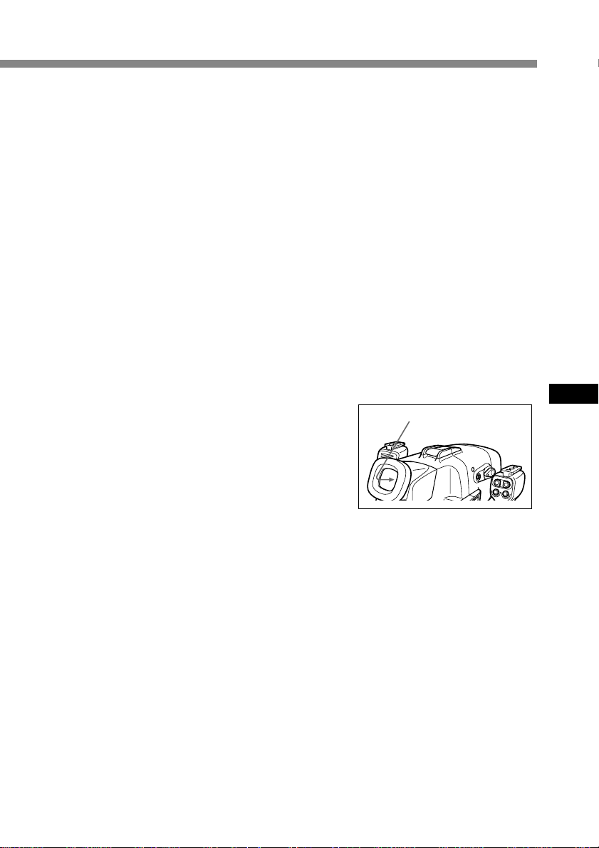
El tamaño del objeto debajo del agua
Puesto que el índice de refracción debajo del agua es más alto que en el aire, los objetos
aparecen 1/4 más cerca y, por tanto, más grandes. Este fenómeno afecta al objetivo de la
videocámara, así como al ojo humano. Se recomienda el uso del objetivo de conversión
panorámica suministrado.
Controle la cámara con movimientos lentos y estables
Mientras graba, mantenga el cuerpo estable.
Las tomas inestables se ampliarán en la pantalla del TV.
Mueva la videocámara lo más despacio posible. Puesto que la mayoría de los objetos
debajo del agua se mueven, es posible obtener imágenes buenas sin mucha necesidad
de mover la videocámara.
Nota sobre la grabación submarina
Asegúrese de seguir las normas de seguridad del submarinismo, como las relacionadas
con la duración de la inmersión y la profundidad.
Fugas de agua
La funda submarina está diseñada para
ser impermeable; no obstante, si entra
agua, parpadeará el indicador LEAK
(amarillo).
En este caso, saque la funda submarina
del agua lo antes posible,
manteniéndola en posición horizontal.
Asegúrese de seguir las normas de
seguridad del submarinismo al subir a
la superficie.
Seque la funda submarina con un paño suave y ábrala.
Para apagar el indicador, desconecte el cable de control remoto.
Compruebe la causa de la fuga.
Si la videocámara se ha mojado, llévela inmediatamente al proveedor Sony más
próximo.
Se recomienda la adquisición de un seguro de daños a propiedad para el material
submarino por si se produce una emergencia.
Indicador LEAK
(amarillo)
Después del uso
• Después de grabar en el mar, sumerja la funda submarina en agua de grifo o en agua
dulce entre 30 y 60 minutos antes de abrir los cierres para eliminar completamente la
sal de la funda submarina, el filtro y el objetivo de conversión panorámica.
• Si va a utilizar la videocámara cerca del mar durante mucho tiempo, se recomienda
que acuda a un proveedor Sony periódicamente para su revisión.
ES
17-ES
Page 62

Extracción de la videocámara
Antes de abrir la funda submarina, aclárela con agua dulce y séquela con un paño
suave. Asegúrese de secarse antes de abrir la funda marina. Procure también que no
caigan gotas de agua de su traje de buceo.
1 Retire el asa.
2 Para DCR-TRV6E/TRV8E/
TRV9E/TRV10E/TRV11E/
TRV20E/TRV890E/TRV900E
Desenganche los 3 cierres y abra
la funda submarina.
Desconecte el cable del monitor de
la zapata de montaje de cámara B.
3 Extraiga la videocámara de la
carcasa frontal.
Sujete la zapata de montaje de
cámara por los mandos y extraiga
la videocámara.
Al abrir la funda submarina, no tire
con fuerza del enchufe del cable del
monitor.
18-ES
4 Desconecte el enchufe de control
remoto y el enchufe del
micrófono.
5 Para DCR-TRV6E/TRV8E/
TRV9E/TRV10E/TRV11E/
TRV20E/TRV890E/TRV900E
Desconecte el cable de conexión A/
V de la zapata de montaje de
cámara B de la toma AUDIO/
VIDEO.
Para DCR-TRV7E
Desconecte el enchufe del monitor
de la toma AUDIO/VIDEO.
Page 63

6 Retire la zapata de montaje de cámara con el destornillador.
B
Afloje el tornillo de la placa de tornillo y retire la zapata de montaje de cámara de la
videocámara.
7 Extraiga la batería del monitor LCD.
Después de utilizar la funda submarina
• Inserte el enchufe del cable de
conexión A/V en el portaenchufes de
la zapata de montaje de cámara B.
• Inserte los enchufes de control
remoto y del micrófono en el
portaenchufes del interior de la
carcasa frontal.
ES
19-ES
Page 64

Nota sobre el anillo en O
El anillo en O asegura la impermeabilidad de la funda submarina. Para mantener la
integridad de la impermeabilidad, utilícela correctamente.
Es posible que entre agua si se
manipula de forma incorrecta.
Compruebe el anillo en O
Cada vez que vaya a utilizar la funda submarina, verifique que no hay arañazos ni
grietas en el anillo en O y evite la acumulación de polvo en él, ya que podría permitir la
entrada de agua.
• Extraiga el anillo en O de la muesca con el dedo. No utilice una herramienta metálica
ni puntiaguda.
• Coloque el anillo en O en la muesca uniformemente. No lo retuerce nunca.
• Compruebe que no hay grietas ni polvo en el anillo en O y, a continuación, cúbralo
ligeramente con la grasa suministrada utilizando el dedo. Ello evita el desgaste.
• Al aplicar la grasa, vuelva a comprobar si hay grietas o polvo. Nunca utilice un paño
o papel para aplicar la grasa, ya que las fibras pueden quedar pegadas al anillo en O.
Si se le acaba la grasa de silicona (2-115-921-01), podrá adquirir más en el Centro
de servicio técnico Sony más próximo.
Elimine el polvo, arena o restos de cabello del anillo en O.
Asegúrese de que no hay polvo, arena ni restos de cabello en el anillo en O, la muesca o
la superficie de la funda submarina que entra en contacto con el anillo en O. En caso
afirmativo, límpielo límpielos completamente. De lo contrario, podrían resultar
dañados el anillo en O y la superficie de la funda submarina y podría entrar agua.
Anillo en O
20-ES
Procure que la funda submarina no apriete el anillo en O
Al unir las carcasas frontal y posterior, tenga cuidado para que el anillo en O no quede
pinzado entre ambas carcasas. Si esto ocurre, no sólo se dañará el anillo en O, sino que
entrará agua.
Vida útil del anillo en O
Según el mantenimiento y la duración del uso, se recomienda la sustitución del anillo en
O cada año o dos años.
El anillo en O (3-977-362-01) puede sustituirse en el Centro de servicio técnico Sony más
próximo.
Almacenamiento del anillo en O
Guarde un anillo en O de reserva en su embalaje en un lugar fresco y seco. No lo guarde
en un lugar muy caluroso, frío o húmedo. Tenga cuidado para no doblarlo ni colocar
objetos pesados sobre él.
Page 65

Precauciones sobre el manejo
Después del uso
Si deja agua salada en la funda submarina, las piezas metálicas se oxidarán y el
movimiento de los interruptores de operación resultará perjudicado. Si entra agua de
mar a través de arañazos en el recubrimiento, la sal puede corroer las piezas metálicas
de la funda submarina y provocar la caída del recubrimiento. Después de grabar en el
mar, sumerja la funda submarina en agua de grifo o en agua dulce durante unos 30
minutos antes de abrir las hebillas para eliminar completamente la sal de la funda
submarina, el filtro y el objetivo de conversión panorámica.
Después de lavarla, utilice un paño suave para eliminar el agua del interior de la funda
submarina y de la videocámara cargada.
* Tome siempre las precauciones anteriores al utilizar la funda submarina.
Al abrir la funda submarina o cambiar la batería situada en el asa, tenga cuidado para
que no caigan gotas de agua de su traje de submarinismo o cabello.
No deje la funda submarina bajo la luz solar directa durante un periodo prolongado, ya
que la temperatura puede aumentar en su interior, dañando los equipos colocados. Si
ha de exponer la funda submarina a la luz solar directa, asegúrese de taparla con una
toalla u otra protección.
Al almacenar la funda submarina
Cubra el anillo en O ligeramente con la grasa suministrada y colóquelo correctamente
en la muesca. Una las carcasas frontal y posterior y guárdela en un lugar fresco y seco
sin cerrar las hebillas.
Procure no almacenar la funda submarina en un lugar muy caluroso, frío o húmedo, o
junto con naftalina o alcanfor, ya que estas condiciones pueden dañar a la unidad.
ES
Transporte
Al transportar la funda submarina, asegúrese de extraer la videocámara. En caso
contrario, la unidad puede sufrir daños.
Nota
Al utilizar la bolsa de transporte
suministrada, instale el cinturón de
transporte suministrado y ajuste la
longitud del cinturón.
Evite manejarla con brusquedad y
someterla a golpes. Se recomienda
tapar la funda submarina con una toalla
u otra protección.
21-ES
Page 66

Identificación de componentes y controles
Enchufe del monitor
Carcasa
posterior
Compartimiento
del NP-F330
Compartimiento
de las baterías secas
Detector de
control remoto
Asa
Botón AUTO
FOCUS ON/OFF
Enchufe de control remoto (azul)
Indicador REC (rojo)
Indicador LEAK (amarillo)
Transmisor
de control
remoto
Riel de guía
Indicador de
comprobación
de la batería
Carcasa
frontal
Zapata para
luz de vídeo
Cristal frontal
Micrófono
submarino
(monofónico)
Interruptor
POWER
Anillo en O
Botón ZOOM
Monitor LCD
Zapata de montaje de cámara A
Espaciador para la zapata de
montaje de cámara B
(zapata de montaje de cámara C)
Zapata de montaje de cámara B
Zapata de montaje de cámara D
22-ES
Botón PHOTO
Botón
START/STOP
Enchufe del micrófono
B
Cable de conexión A/V
Placa de tornillo
Page 67

Especificaciones
Material
Aleación de aluminio, cristal, plástico (ABS, PC)
Impermeabilización
Anillo en O, 3 cierres
Profundidad óptima
Hasta 75 metros
Micrófono submarino
Micrófono de condensador (monofónico)
Funciones controlables
Encendido/apagado, inicio/parada de grabación, activación/desactivación del enfoque
automático, zoom electrónico,
grabación fotográfica en cintas (sólo DCR-TRV6E/TRV8E/TRV9E/TRV10E/TRV11E/TRV20E/
TRV890E/TRV900E)
Dimensiones
Aprox. 312 x 212 x 318 mm (an/al/prf)
Peso
Aprox. 4,4 kg (sólo la unidad)
Accesorios suministrados
Zapatas de montaje de cámara A, B, D (1 de cada)
Espaciador para la zapata de montaje de cámara B (zapata de montaje de cámara C) (1)
Placa de tornillo (2)
Pieza para destornillador (1)
Objetivo de conversión panorámica (1)
Filtro en color (1)
Batería NP-F330 para el monitor (1)
Batería de litio CR2 (1)
Grasa (1)
Anillo en O (1)
Parasol (1)
Anillo antirreflejos (2)
Correa (3)
Almohadilla para la batería (1)
Bolsa de transporte (1)
Cinturón de transporte (1)
Manual de instrucciones (1)
Garantía (1)
Accesorio recomendado
Luz de vídeo submarina HVL-ML20
ES
Diseño y especificaciones sujetos a cambios sin previo aviso.
23-ES
Page 68

Für Kunden in Deutschland
Richtlinie: EMV-Richtlinie 89/386/EWG, 92/
31/EWG
Dieses Gerät entspricht bei Verwendung in
folgenden Umgebungen den EMVBestimmungen:
• Wohngegenden
• Gewerbegebieten
• Leichtindustriegebieten
(Dieses Gerät entspricht den EMVStandardbestimmungen EN55022 Klasse B.)
Entsorgungshinweis: Bitte werfen Sie nur
entladene Batterien in die Sammelboxen beim
Handel oder den Kommunen. Entladen sind
Batterien in der Regel dann, wenn das Gerät
abschaltet und signalisiert “Batterie leer”
oder nach längerer Gebrauchsdauer der
Batterien “nicht mehr einwandfrei
funktioniert”. Um sicherzugehen, kleben Sie
die Batteriepole z.B mit einem Klebestreifen
ab oder geben Sie die Batterien einzeln in
einen Plastikbeutel.
2-DE
Page 69

Inhalt
Merkmale und Sicherheitsmaßnahmen ... 3
Mitgeliefertes Zubehör ............................... 4
Vorbereitungen ............................................ 5
Vorbereiten des Camcorders ............... 5
Vorbereiten des Unterwassergehäuses
(Akku einlegen) ..................................... 9
Installieren des Camcorders im
Unterwassergehäuse .......................... 11
Aufnahme ................................................... 13
Anbringen des mitgelieferten
Zubehörs .............................................. 14
Anbringen des Sonderzubehörs ....... 15
Unterwasseraufnahmen ........................... 16
Eindringen von Wasser ...................... 17
Herausnehmen des Camcorders ............. 18
Hinweis zum Dichtungsring.................... 20
Sicherheitshinweise zur Pflege und
Handhabung .............................................. 21
Lage und Funktion der Teile und
Bedienelemente .......................................... 22
Technische Daten....................................... 23
Merkmale und Sicherheitsmaßnahmen
• Das MPK-DVF3 ist für den Camcorder Handycam Vision™ DCR-TRV6E/TRV7E/
TRV8E/TRV9E/TRV10E/TRV11E/TRV20E/TRV890E/TRV900E von Sony geeignet.
• Aufnahmen bei Tiefen von bis zu 75 Metern sind möglich.
• Folgende Funktionen lassen sich unter Wasser ausführen:
– Ein- und Ausschalten
– Autofokus ein/aus
– Aufnahme starten/stoppen
– Fotoaufnahmen auf Band (nur DCR-TRV6E/TRV8E/TRV9E/TRV10E/TRV11E/
TRV20E/TRV890E/TRV900E)
– Elektronischer Zoom
– Wiedergabe auf dem LCD-Bildschirm
DE
Sony übernimmt keine Haftung für Schäden an der Videokamera, am Akku usw.
im Unterwassergehäuse oder für den Verlust vorheriger Aufnahmen, wenn
aufgrund fehlerhafter Bedienung Wasser in das Gehäuse eindringt.
Dieses Logo zeigt an, daß es sich bei diesem Produkt um
Originalzubehör für Videogeräte von Sony handelt. Wenn Sie
Videogeräte von Sony erwerben, achten Sie bitte auch beim Kauf
von Zusatzkomponenten und -geräten darauf, daß sie mit dem Logo
“GENUINE VIDEO ACCESSORIES” gekennzeichnet sind.
3-DE
Page 70

Mitgeliefertes Zubehör
Überprüfen Sie, ob das folgende Zubehör mit Ihrem Unterwassergehäuse geliefert
wurde.
123
B
45
7
0qa
qd qf
1 Kameramontageschuh A (1)
für DCR-TRV7E
2 Kameramontageschuh B (1)
für DCR-TRV6E/TRV8E/TRV9E/
TRV10E/TRV11E/TRV20E/TRV890E/
TRV900E
3 Abstandsplatte für
Kameramontageschuh B
(Kameramontageschuh C) (1)
für DCR-TRV8E/TRV10E
4 Kameramontageschuh D (1)
für DCR-TRV6E/TRV11E/TRV20E
5 Schraubenplatte für
Kameramontageschuh B und D (2)
6 Schraubendreherteil (1)
4-DE
Befestigung für Kameramontageschuh B
8
6
9
qs
qg
7 Akku NP-F330 für den LCD-Bildschirm
(1)
8 Lithium-Ionen-Akku CR2 (1)
9 Dichtungsring (1)
0 Unterwasser-Weitwinkelkonverter
(VCL-MK2) (1)
qa Sonnenschutz (1)
qs Antireflexring (2)
Groß: ø 37 mm (1)
Klein: ø 30 mm (1)
qd Farbfilter (VF-MK2) (1)
qf Fett (1)
qg Tragetasche (1) Trageriemen (1)
Akkupolster (1) Riemen (3)
Page 71

Vorbereitungen
Vorbereiten des Camcorders
Bereiten Sie den Camcorder vor dem Installieren im Unterwassergehäuse wie in diesem
Kapitel erläutert vor. Für die Abbildungen wurde das Modell DCR-TRV20E verwendet.
Andernfalls wird die Modellnummer in den Abbildungen angegeben. Auf
Unterschiede in der Bedienung der anderen Modelle wird im Text deutlich
hingewiesen, zum Beispiel mit der Anmerkung “nur DCR-TRV20E”.
Das Vorgehen kann je nach Camcorder-Typ variieren.
Näheres dazu schlagen Sie bitte in der mit dem Camcorder gelieferten
Bedienungsanleitung nach.
1 Nehmen Sie Objektivschutzkappe,
Schulterriemen, Weitwinkelkonverter,
Filter bzw. Gegenlichtblende vom
Camcorder ab.
2 Bringen Sie einen geladenen Akku an.
3 Legen Sie eine Kassette ein.
4 Bringen Sie den Antireflexring am Objektiv an.
für DCR-TRV7E/TRV9E/TRV20E : ø 37 mm (groß)
für DCR-TRV6E/TRV8E/TRV10E/TRV11E : ø 30 mm (klein)
für DCR-TRV890E/TRV900E : nicht erforderlich
Ziehen Sie den Antireflexring auf keinen Fall zu stark an.
DE
5 Wählen Sie den Kameramontageschuh aus.
Der Kameramontageschuh und die Montageposition der Schraubenplatte
unterscheiden sich je nach Camcorder. Einzelheiten entnehmen Sie bitte der Tabelle
unten.
Kameramontageschuh
A
B
D
Hinweis
Für den DCR-TRV7E verwenden Sie bitte nur den Kameramontageschuh A.
Verwenden Sie nicht Kameramontageschuh B, D und die Schraubenplatte.
Position
der
Schraubenplatte
–
1
2
3
1
2
Camcorder
DCR-TRV7E
DCR-TRV9E
DCR-TRV6E/TRV11E/
TRV20E/TRV890E/
TRV900E
DCR-TRV8E/TRV10E
DCR-TRV20E
DCR-TRV6E/TRV11E
1
Montageposition der
Schraubenplatte am
Kameramontageschuh B
Fortsetzung
5-DE
Page 72

Vorbereitungen (Fortsetzung)
6 Bringen Sie den Kameramontageschuh an.
Für DCR-TRV7E
Verwenden Sie
Kameramontageschuh A.
Befestigen Sie die Schraube von
Kameramontageschuh A an der
Stativbohrung des Camcorders,
und ziehen Sie sie fest an.
Für DCR-TRV9E/TRV890E/TRV900E
Verwenden Sie Kameramontageschuh
B und die Schraubenplatte.
1 Überprüfen Sie anhand der
Tabelle auf Seite 5, welche
Montageposition (1, 2 oder 3)
für die Schraubenplatte an
Ihrem Camcorder geeignet ist.
2 Bringen Sie die Schraubenplatte
so an, daß die Verriegelung an
der Unterseite von
Kameramontageschuh B
einrastet.
3 Befestigen Sie die Schraube der
Schraubenplatte an der
Stativbohrung des Camcorders,
und ziehen Sie sie fest an.
4 Schließen Sie das A/V-Kabel
des Kameramontageschuhs an
die Buchse AUDIO/VIDEO des
Camcorders an.
Nehmen Sie das
Schraubendreherteil ab.
Ziehen Sie
die Schraube
fest an.
B
Kameramontageschuh
B
Schraubenplatte
6-DE
Page 73

Für DCR-TRV8E/TRV10E
Verwenden Sie
Kameramontageschuh B,
Abstandsplatte
(Kameramontageschuh C) und die
Schraubenplatte.
1 Bringen Sie die Abstandsplatte
an Kameramontageschuh B an.
2 Bringen Sie die Schraubenplatte
an Position 3 von
Kameramontageschuh B so an,
daß die Verriegelung an der
Unterseite des Schuhs einrastet.
3 Befestigen Sie die Schraube der
Schraubenplatte an der
Stativbohrung des Camcorders,
und ziehen Sie sie fest an.
4 Schließen Sie das A/V-Kabel
des Kameramontageschuhs an
die Buchse AUDIO/VIDEO des
Camcorders an.
3
Montageposition
der Schraubenplatte
am Kameramontageschuh B
Abstandsplatte
(Kameramontageschuh
C)
Kameramontageschuh
B
Schraubenplatte
Für DCR-TRV6E/TRV11E/TRV20E
Verwenden Sie
Kameramontageschuh B, D und die
Schraubenplatte.
1 Bringen Sie die Schraubenplatte
an Position 1 von
Kameramontageschuh D so an,
1
2
daß die Verriegelung an der
Unterseite von Schuh D einrastet.
2 Befestigen Sie die Schraube der
Schraubenplatte von Schuh D an
der Stativbohrung des
Camcorders, und ziehen Sie sie
fest an.
3 Montieren Sie die Schraubenplatte
an der Position 2 von Schuh B.
4 Befestigen Sie die Schraube der
Schraubenplatte von Schuh B an
der Bohrung von Schuh D des
Camcorders, und ziehen Sie sie
B
fest an.
5 Schließen Sie das A/V-Kabel des
Kameramontageschuhs an die
Buchse AUDIO/VIDEO des
Camcorders an.
Nun können Sie den Camcorder im Unterwassergehäuse installieren.
Überprüfen Sie unbedingt, ob der Kameramontageschuh fest am Camcorder
befestigt ist, bevor Sie den Camcorder im Unterwassergehäuse installieren.
Montageposition
der Schraubenplatte
am
Kameramontageschuh D
Kameramontageschuh
D
Kameramontageschuh
B
Schraubenplatte
Fortsetzung
DE
7-DE
Page 74

Vorbereitungen (Fortsetzung)
7 Bereiten Sie die Aufnahme vor.
Vor dem Installieren des Camcorders im Unterwassergehäuse müssen Sie den
Camcorder für die Aufnahme vorbereiten.
Für DCR-TRV7E
1 Stellen Sie den Schalter POWER
auf CAMERA.
2 Setzen Sie COMMANDER im
Menüsystem auf ON.
3 Schalten Sie folgende
Funktionen aus: BACK LIGHT,
NightShot, PROGRAM AE und
Bildeffekt.
4 Schieben Sie den Schiebeschalter
AUTO LOCK nach oben auf
AUTO.
5 Wählen Sie V-OUT/LCD im
Menü DISPLAY, und drücken
Sie die Taste DISPLAY am
Camcorder, bevor Sie ihn im
Unterwassergehäuse
installieren.
Für DCR-TRV6E/TRV8E/TRV9E/TRV10E/TRV11E/TRV20E/
TRV890E/TRV900E
1 Stellen Sie den Schalter POWER
auf CAMERA.
2 Setzen Sie COMMANDER im
Menüsystem auf ON.
3 Schalten Sie folgende
Funktionen aus: BACK LIGHT,
NightShot, PROGRAM AE und
Bildeffekt.
4 Stellen Sie den Schalter FOCUS
auf AUTO.
5 Wählen Sie V-OUT/LCD im
Menü DISPLAY, und drücken
Sie die Taste DISPLAY am
Camcorder, bevor Sie ihn im
Unterwassergehäuse
installieren.
Schalter
AUTO LOCK
Taste MENU
Schalter POWER
Schalter FOCUS
Schalter
POWER
8-DE
Taste MENU
* Wenn Sie an Ihrem Camcorder die Möglichkeit haben, schalten Sie die Anzeige
REC aus (OFF). Dies verhindert, daß sie aufgenommen wird, wenn Sie den
Camcorder in das Unterwassergehäuse einsetzen. Näheres dazu schlagen Sie
bitte in der mit dem Camcorder gelieferten Bedienungsanleitung nach.
Page 75

Vorbereiten des Unterwassergehäuses (Akku einlegen)
1 Nehmen Sie den Griff ab.
Lösen Sie die Schraube an der
Unterseite des
Unterwassergehäuses.
2 Legen Sie den Lithium-Akku in den Griff ein.
1 Nehmen Sie die Schraube mit
dem mitgelieferten
Schraubendreherteil ab.
2 Legen Sie den mitgelieferten
Lithium-Akku (CR2, x 1) wie auf
dem Griff dargestellt
polaritätsrichtig ein.
3 Ziehen Sie die Schraube fest an.
DE
3 Lösen Sie die drei
Verriegelungen, und öffnen Sie
das Unterwassergehäuse.
Wenn die Verschlußklappen
geöffnet sind und Sie die
Metallbeschläge in Richtung des
Suchers anheben, stoppen die
Verschlußklappen.
Fortsetzung
9-DE
Page 76
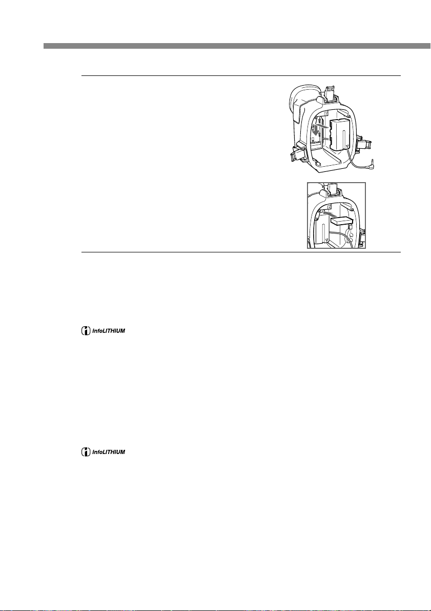
Vorbereitungen (Fortsetzung)
4 Bringen Sie den mitgelieferten
Akku NP-F330 für den LCDBildschirm an der hinteren
Verkleidung an. Laden Sie den
Akku vor dem Anbringen
unbedingt vollständig auf.
Hinweis
Schieben Sie das mitgelieferte Akkupolster wie in
der Abbildung dargestellt fest hinein, damit sich
der Akku nicht lösen können, falls er starken
Stößen ausgesetzt wird.
Hinweis zum mitgelieferten Akku NP-F330
Was ist ein “InfoLITHIUM”-Akku?
Ein “InfoLITHIUM” ist ein Lithium-Ionen-Akku, der Informationen über seinen
Ladezustand an kompatible elektronische Geräte übermitteln kann. Wir von Sony
empfehlen, den “InfoLITHIUM”-Akku in elektronischen Geräten mit der Markierung
* Je nach Zustand und Umgebungsbedingungen, in denen das Gerät eingesetzt
• Zum Laden des mitgelieferten Akkus NP-F330 verwenden Sie ein Netzteil/
Ladegerät, das Infolithium-Akkus des L-Typs laden kann (nicht mitgeliefert).
• Sie können auch ein Netzteil/Ladegerät für Infolithium-Akkus des L-Typs und für
NP-F530/F550 verwenden (nicht mitgeliefert).
• Die Aufnahmedauer bei einem vollständig geladenen Akku NP-F330 beträgt etwa 6
Stunden (ununterbrochene Aufnahme). Je nach Gebrauch kann die tatsächliche
Aufnahmedauer kürzer sein.
zu verwenden.
wird, ist die Anzeige möglicherweise nicht ganz präzise.
“InfoLITHIUM” ist ein Warenzeichen der Sony Corporation.
10-DE
Der “InfoLITHIUM”-Akku kann wiederverwertet werden. Wenn der
Akku leer ist und sich nicht mehr laden läßt, decken Sie die
Metallbereiche des Akkus mit Isoliermaterial wie z. B. Klebeband ab,
und bringen Sie ihn zu einer Akkuverwertungsstelle.
Hinweise zum LCD-Bildschirm
• Auf dem LCD-Bildschirm erscheinen keine Bilder, wenn er nicht ordnungsgemäß an
den Camcorder angeschlossen ist.
• Die auf dem LCD-Bildschirm angezeigte verbleibende Betriebsdauer bezieht sich auf
den Akku im Camcorder und nicht auf die verbleibende Betriebsdauer des Akkus im
LCD-Bildschirm.
• Der LCD-Bildschirm des Unterwassergehäuses ist nicht für den “InfoLITHIUM”Akku geeignet.
Page 77

Installieren des Camcorders im Unterwassergehäuse
1 Installieren Sie den Camcorder im Unterwassergehäuse.
Für DCR-TRV7E
Schließen Sie den Stecker für den
Bildschirm an.
1 Entfernen Sie den Haken für das
Bildschirmkabel.
2 Schließen Sie den
Bildschirmstecker an die Buchse
AUDIO/ VIDEO des
Camcorders an.
Haken für Bildschirmkabel
Durchschieben, dann nach außen ziehen.
Schließen Sie den
Fernbedienungsstecker und den
Mikrofonstecker an.
3 Schließen Sie den
Mikrofonstecker an die Buchse
MIC an (Plug-in-Power).
4 Schließen Sie den
Fernbedienungsstecker an die
Steuerbuchse LANC an.
Hinweis
Damit die Kabel sich nicht verdrehen oder
durchhängen, achten Sie darauf, die Stecker richtig
herum in die Buchsen zu stecken, wie auf der
Abbildung zu sehen.
hintere Verkleidung
an die Buchse AUDIO/ VIDEO
vordere Verkleidung
an die
an die
Steuerbuchse
LANC
Buchse
MIC
(Plug-inPower)
DE
Für DCR-TRV9E/TRV10E/TRV20E/TRV900E
Schließen Sie den
Fernbedienungsstecker und den
Mikrofonstecker an.
1 Schließen Sie den
Mikrofonstecker an die Buchse
MIC an (Plug-in-Power).
2 Schließen Sie den
Fernbedienungsstecker an die
Steuerbuchse LANC an.
an die Steuerbuchse LANC
vordere Verkleidung
an die Buchse MIC
(Plug-in-Power)
Fortsetzung
11-DE
Page 78

Vorbereitungen (Fortsetzung)
2 Schieben Sie den Camcorder
hinein, bis der Montageschuh mit
einem Klicken einrastet.
3 Für DCR-TRV6E/TRV8E/
TRV9E/TRV10E/TRV11E/
TRV20E/TRV890E/TRV900E
Schließen Sie das Bildschirmkabel
an die Buchse des
Kameramontageschuhs B an.
Die Kabel werden werkseitig in
die Steckerhalter des
Unterwassergehäuses gesteckt.
Ziehen Sie bei Gebrauch des
Geräts die Stecker aus den
Haltern.
12-DE
4 Bringen Sie die vordere Verkleidung
an der hinteren Verkleidung an.
Halten Sie beide Verkleidungen gut
fest, und schließen Sie die 3
Verriegelungen fest.
Achten Sie darauf, daß das
Fernbedienungs-, das Mikrofon- und
das Bildschirmkabel nicht
eingeklemmt werden. Andernfalls
kann Wasser eindringen.
Erläuterungen zum Dichtungsring
finden Sie auf Seite 20.
5 Bringen Sie den Griff an.
Ziehen Sie die Schraube fest an.
Damit sind die Vorbereitungen abgeschlossen. Überprüfen Sie vor dem Tauchen
unbedingt, ob die Ausrüstung richtig funktioniert und kein Wasser eindringt
(siehe Seite 16).
Page 79

Aufnahme
Sie können nun Unterwasseraufnahmen machen.
Wenn Sie mit dem Camcorder tauchen, tauchen Sie bitte langsam, und achten Sie auf
die Umgebung. Stoßen Sie das Unterwassergehäuse auf keinen Fall gegen Felsen oder
Riffe usw.
Schalter POWER
Taste AUTO
FOCUS ON/OFF
Anzeige REC
(rot)
Anzeige LEAK
(gelb)
Taste ZOOM
Taste PHOTO
Taste START/STOP
1 Stellen Sie den Schalter POWER auf ON.
Der Camcorder schaltet sich ein, und ein Bild erscheint auf dem LCD-Bildschirm.
2 Starten Sie die Aufnahme mit der Taste START/STOP.
Die Anzeige REC (rot) leuchtet beim Aufnehmen auf.
Um die Aufnahme zu beenden, drücken Sie erneut die Taste START/STOP.
Zoom-Funktion
Drücken Sie die Taste ZOOM.
Drücken Sie T für Telephoto (Motiv erscheint näher) bzw. W für Weitwinkel (Motiv
erscheint weiter entfernt). Die Zoom-Geschwindigkeit des Camcorders läßt sich nicht
einstellen.
Aufnehmen eines Standbildes auf Band (Fotoaufnahmen auf
Band) (nur DCR-TRV6E/TRV8E/TRV9E/TRV10E/TRV11E/TRV20E/
TRV890E/TRV900E)
Zum Aufnehmen eines Standbildes drücken Sie die Taste PHOTO. Das Standbild, das
auf dem LCD-Bildschirm angezeigt wird, wird aufgenommen. Beachten Sie, daß Sie das
aufgezeichnete Bild nicht überprüfen können, auch wenn Sie die Taste PHOTO leicht
drücken. Die Speicherfotofunktion steht bei den Modellen DCR-TRV10E/TRV11E/
TRV20E/TRV900E nicht zur Verfügung. Näheres dazu schlagen Sie bitte in der mit
dem Camcorder gelieferten Bedienungsanleitung nach.
DE
So bleibt ein Motiv scharf gestellt
Schalten Sie den Autofokus mit der Taste AUTO FOCUS ON/OFF aus (OFF). Das
Motiv bleibt fokussiert, auch wenn Fische zwischen dem Camcorder und dem Motiv
schwimmen. Drücken Sie die Taste AUTO FOCUS ON/OFF erneut, um den Camcorder
in den Modus für automatische Fokussierung zu schalten.
Hinweis
Bedecken Sie den Steuersignalsender oder -detektor nicht mit den Fingern. Das
Fernbedienungssignal für die einzelnen Funktionen wird vom Griff an das
Unterwassergehäuse übertragen.
Fortsetzung
13-DE
Page 80

Aufnahme (Fortsetzung)
Anbringen des mitgelieferten Zubehörs
Anbringen des mitgelieferten Weitwinkelkonverters
Da Gegenstände unter Wasser um 1/4
näher und deshalb größer erscheinen,
empfiehlt es sich, den
Weitwinkelkonverter anzubringen,
wenn Sie Bilder mit größerer
Raumwirkung aufnehmen wollen.
Beachten Sie jedoch, daß Gegenstände
dadurch kleiner erscheinen.
Hinweis
Der mitgelieferte
Weitwinkelkonverter darf
ausschließlich unter Wasser
eingesetzt werden.
Der mitgelieferte Sonnenschutz
Der mitgelieferte Sonnenschutz
verringert Reflexionen auf dem LCDBildschirm.
Anbringen des mitgelieferten Farbfilters
Wenn Sie den mitgelieferten Farbfilter
benutzen, bringen Sie ihn auf dem
Weitwinkelkonverter an.
Wasser absorbiert Licht, vor allem
Rotlicht, so daß Motive in tiefem
Wasser bläulich erscheinen. Die Farbe
von Gegenständen hängt von der
Klarheit des Wassers ab.
Um eine möglichst natürliche
Farbwirkung zu erzielen, verwenden
Sie den mitgelieferten Farbfilter.
Setzen Sie den Weitwinkelkonverter so
ein, daß er fest sitzt.
Mitgelieferter
Sonnenschutz
Weitwinkelkonverter
Farbfilter
14-DE
Sie können Weitwinkelkonverter, Sonnenschutz und Farbfilter unter Wasser
anbringen und abnehmen.
Wenn das Bild auf dem LCD-Bildschirm nicht scharf ist, da sich Luft zwischen diesen
Zubehörteilen und dem Unterwassergehäuse befindet, bringen Sie sie unter Wasser neu
an.
Anbringen des mitgelieferten Riemens
Bringen Sie den Riemen wie in der
Abbildung dargestellt an.
Bringen Sie die mitgelieferten Riemen
an, damit Sie diese Zubehörteile nicht
verlieren, wenn Sie sie an Land oder
unter Wasser abnehmen.
So bringen Sie den
Riemen an
Weitwinkelkonverter
Farbfilter
Sonnenschutz
Page 81

Anbringen des Sonderzubehörs
Unterwasservideoleuchte
In tiefem Wasser oder unter Felsen, wo
kein Sonnenlicht hingelangt, empfiehlt
es sich, mit Unterwasservideoleuchten
aufzunehmen.
Sie können diese Videoleuchten an den
Videoleuchtenschuhen oben an den
beiden Griffen anbringen.
Unterwasservideoleuchten wie z. B.
HVL-ML20 von Sony (nicht
mitgeliefert)
Zum Anbringen an die
Videoleuchtenschuhe an
beiden Seiten
DE
15-DE
Page 82

Unterwasseraufnahmen
Vorbereitungen für das Tauchen
Überprüfen Sie, bevor Sie tiefer tauchen, in einer Wassertiefe von etwa einem Meter, ob
die Ausrüstung korrekt funktioniert und kein Wasser eindringt.
Schützen Sie die Geräte vor salziger Seeluft. Achten Sie darauf, daß kein Wasser auf die
Geräte spritzt.
Öffnen Sie das Unterwassergehäuse nicht unter Wasser oder am Strand.
Vorbereitungen wie Einsetzen oder Überprüfen der Geräte sollten Sie an einem Ort
ausführen, an dem die Geräte keiner Feuchtigkeit und keiner salzigen Seeluft
ausgesetzt sind.
Überprüfen Sie vor dem Tauchen nochmals folgende Punkte:
s Sorgen Sie dafür, daß der Akku des Unterwassergehäuses und der des
Camcorders vollständig geladen sind.
• Es empfiehlt sich, Akkus mit einer großen Kapazität zu benutzen und einen
Ersatzakku bereitzuhalten.
s Achten Sie darauf, daß auf dem Videoband noch genügend restliche
Aufnahmedauer zur Verfügung steht.
s Überprüfen Sie, daß der Dichtungsring keine Kratzer oder Risse aufweist.
s Zwischen der vorderen und der hinteren Verkleidung darf sich kein Staub, Sand
oder Haar befinden.
s Der Lithiumakku muß ausreichend geladen sein.
• Die Blitzanzeige leuchtet auf,
wenn die Akkurestladung
ausreicht. Richten Sie sich nach
dieser Anzeige. Wenn die
Blitzanzeige nicht leuchtet,
tauschen Sie den Akku aus. Es
empfiehlt sich, Ersatzakkus
bereitzuhalten.
AkkuAnzeige
Rechter
Griff
16-DE
Umgebungsbedingungen für Unterwasseraufnahmen
Unterwasseraufnahmen unterscheiden sich von Aufnahmen an Land, da
Wasserklarheit, Wassertiefe und die Lichtbedingungen eine entscheidende Rolle
spielen. Im folgenden finden Sie Tips für bessere Unterwasseraufnahmen.
Optimale Zeit für Aufnahmen
Die beste Zeit für Aufnahmen liegt zwischen 10:00 und 14:00 Uhr. Wenn die Sonne am
höchsten steht, erzielen Sie die besten Ergebnisse.
Wenn Sie bei Nacht oder an dunklen Stellen aufnehmen wollen, wo kein Sonnenlicht
hingelangt, verwenden Sie eine starke Unterwasservideoleuchte.
Page 83

Größe des Motivs unter Wasser
Da der Brechungskoeffizient unter Wasser höher ist als in der Luft, erscheinen
Gegenstände um 1/4 näher und deshalb größer. Dieses Phänomen gilt für das Objektiv
am Camcorder ebenso wie für das menschliche Auge. Es empfiehlt sich daher, den
mitgelieferten Weitwinkelkonverter zu verwenden.
Bewegen Sie die Kamera langsam oder gar nicht
Halten Sie sich beim Aufnehmen ruhig.
Unruhige Aufnahmen wirken auf dem Fernsehschirm noch unruhiger.
Bewegen Sie den Camcorder so langsam wie möglich. Da sich die meisten Motive unter
Wasser bewegen, können Sie interessante Aufnahmen erzielen, ohne den Camcorder zu
stark zu bewegen.
Hinweis zum Aufnehmen unter Wasser
Beachten Sie unbedingt die Sicherheitsvorschriften beim Tauchen wie Tauchdauer und
-tiefe.
Eindringen von Wasser
Das Unterwassergehäuse ist eigentlich
wasserdicht. Sollte dennoch Wasser
eindringen, blinkt die Anzeige LEAK
(gelb).
Nehmen Sie in einem solchen Fall das
Unterwassergehäuse so schnell wie
möglich aus dem Wasser, und halten
Sie es waagrecht. Tauchen Sie gemäß
den Sicherheitsvorschriften beim
Tauchen auf.
Trocknen Sie das Unterwassergehäuse mit einem weichen Tuch ab, und öffnen Sie es.
Zum Ausschalten der Anzeige lösen Sie das Fernbedienungskabel.
Stellen Sie die Ursache für das eingedrungene Wasser fest.
Anzeige LEAK (gelb)
DE
Wenn der Camcorder naß ist, bringen Sie ihn umgehend zum nächsten Sony-Händler.
Es empfiehlt sich, für den Notfall eine Schadensversicherung für
Unterwasserausrüstungen abzuschließen.
Nach Gebrauch
• Tauchen Sie das Unterwassergehäuse nach Unterwasseraufnahmen im Meer etwa 30
- 60 Minuten lang in Leitungs- oder Süßwasser, bevor Sie die Verriegelungen öffnen,
so daß kein Salz mehr auf dem Unterwassergehäuse, Filter und Weitwinkelkonverter
zurückbleibt.
• Wenn Sie den Camcorder lange Zeit in Meeresnähe benutzen, empfiehlt es sich, ihn
regelmäßig bei einem Sony-Händler überprüfen zu lassen.
17-DE
Page 84

Herausnehmen des Camcorders
Spülen Sie das Unterwassergehäuse vor dem Öffnen mit Süßwasser ab, und trocknen
Sie es mit einem weichen Tuch.
Achten Sie beim Öffnen des Unterwassergehäuses darauf, daß Sie nicht mehr naß sind.
Es sollte auch kein Wasser von Ihrem nassen Tauchanzug o. ä. darauf tropfen.
1 Nehmen Sie den Griff ab.
2 Für DCR-TRV6E/TRV8E/
TRV9E/TRV10E/TRV11E/
TRV20E/TRV890E/TRV900E
Lösen Sie die drei
Verriegelungen, und öffnen Sie
das Unterwassergehäuse.
Lösen Sie das Bildschirmkabel vom
Kameramontageschuh B.
3 Nehmen Sie den Camcorder aus der
vorderen Verkleidung heraus.
Halten Sie den Kameramontageschuh an
den Knöpfen, und ziehen Sie den
Camcorder heraus.
Ziehen Sie beim Öffnen des
Unterwassergehäuses nicht mit Gewalt
am Kabel für den Bildschirmstecker.
18-DE
4 Lösen Sie den Fernbedienungs-
und den Mikrofonstecker.
5 Für DCR-TRV6E/TRV8E/
TRV9E/TRV10E/TRV11E/
TRV20E/TRV890E/TRV900E
Lösen Sie das A/V-Verbindungskabel des
Kameramontageschuhs B von der Buchse
AUDIO/VIDEO.
Für DCR-TRV7E
Lösen Sie den Bildschirmstecker
von der Buchse AUDIO/VIDEO.
Page 85

6 Nehmen Sie den Kameramontageschuh mit Hilfe des Schraubendrehers ab.
B
Lösen Sie die Schraube der Schraubenplatte, und nehmen Sie den
Kameramontageschuh vom Camcorder ab.
7 Nehmen Sie auch den Akku für den LCD-Bildschirm ab.
Nach Gebrauch des Unterwassergehäuses
• Stecken Sie den Stecker des AVVerbindungskabels in den
Steckerhalter am
Kameramontageschuh B.
• Stecken Sie den Fernbedienungs- und
den Mikrofonstecker in den
Steckerhalter an der Innenseite der
vorderen Verkleidung.
DE
19-DE
Page 86

Hinweise zum Dichtungsring
Der Dichtungsring sorgt dafür, daß das Unterwassergehäuse wasserdicht schließt.
Gehen Sie daher ordnungsgemäß mit ihm um.
Andernfalls kann Wasser in das
Gehäuse eindringen.
Überprüfen des Dichtungsrings auf Schäden
Überprüfen Sie vor jedem Benutzen des Unterwassergehäuses, daß der Dichtungsring
keine Kratzer oder Risse aufweist und frei von Staub ist. Andernfalls kann Wasser
eindringen.
• Nehmen Sie den Dichtungsring mit den Fingern aus der Kerbe. Verwenden Sie dazu
kein metallenes oder spitzes Werkzeug.
• Setzen Sie den Dichtungsring gleichmäßig in die Kerbe ein, und verdrehen Sie ihn
nicht.
• Nachdem Sie sich vergewissert haben, daß der Dichtungsring frei von Kratzern oder
Staub ist, fetten Sie ihn leicht mit dem mitgelieferten Fett ein, das Sie mit dem Finger
auf dem Dichtungsring verteilen. Das Fett verhindert eine vorzeitige Abnutzung.
• Überprüfen Sie den Dichtungsring beim Einfetten nochmals auf Risse und Staub.
Verwenden Sie zum Einfetten unter keinen Umständen ein Tuch oder Papier, da
sonst Fasern am Dichtungsring haftenbleiben könnten.
Wenn Ihnen das Silikon-Fett (2-115-921-01) ausgeht, können Sie es im nächsten
Sony-Kundendienstzentrum nachkaufen.
Dichtungsring
20-DE
Entfernen von Staub, Sand oder Haaren vom Dichtungsring
Achten Sie darauf, daß sich kein Staub, Sand oder Haar auf dem Dichtungsring, in der
Kerbe oder auf der Oberfläche des Unterwassergehäuses befindet, an der der
Dichtungsring anliegt. Andernfalls reinigen Sie diese Teile vollständig, da der
Dichtungsring und die Oberfläche des Unterwassergehäuses ansonsten beschädigt
werden könnten und möglicherweise Wasser eindringt.
Klemmen Sie den Dichtungsring nicht am Unterwassergehäuse ein
Achten Sie beim Zusammenfügen von vorderer und hinterer Verkleidung darauf, den
Dichtungsring nicht dazwischen einzuklemmen. Andernfalls wird der Dichtungsring
beschädigt, und Wasser kann eindringen.
Nutzungsdauer des Dichtungsrings
Es empfiehlt sich, den Dichtungsring je nach Wartung und Gebrauchsdauer nach ein
bis zwei Jahren auszutauschen.
Einen Dichtungsring (3-977-362-01) können Sie beim nächsten SonyKundendienstzentrum nachkaufen.
Lagern des Dichtungsrings
Bewahren Sie einen Ersatzdichtungsring an einem kühlen, trockenen Ort in seiner Verpackung
auf. Lagern Sie ihn nicht an einem sehr warmen, kalten oder feuchten Ort. Achten Sie darauf,
ihn nicht zu falten, und stellen Sie keinen schweren Gegenstand darauf.
Page 87

Sicherheitshinweise zur Pflege und Handhabung
Nach Gebrauch
Wenn Sie Salzwasser auf dem Unterwassergehäuse nicht entfernen, rosten die
Metallteile, und die Beweglichkeit der Funktionsschalter wird beeinträchtigt. Wenn
über Kratzer in der Beschichtung Meerwasser eindringt, kann es durch das Salz zur
Korrosion der Metallteile am Unterwassergehäuse kommen, und die Beschichtung
kann sich ablösen. Tauchen Sie das Unterwassergehäuse nach Unterwasseraufnahmen
im Meer etwa 30 Minuten lang in Leitungs- oder Süßwasser, bevor Sie die
Verriegelungen öffnen, so daß kein Salz mehr auf dem Unterwassergehäuse, Filter und
Weitwinkelkonverter zurückbleibt.
Trocknen Sie danach die Innenseite des Unterwassergehäuses und den Camcorder
darin mit einem weichen, trockenen Tuch sorgfältig ab.
* Beachten Sie beim Verwenden des Unterwassergehäuses immer die oben genannten
Sicherheitsmaßnahmen.
Wenn Sie das Unterwassergehäuse öffnen oder den Akku im Griff austauschen, achten
Sie darauf, daß kein Wasser von Ihrem nassen Tauchanzug o. ä. oder aus dem nassen
Haar darauf tropft.
Lassen Sie das Unterwassergehäuse nicht über längere Zeit in direktem Sonnenlicht
liegen. Andernfalls können die Temperaturen im Unterwassergehäuse ansteigen, und
das Gerät darin kann beschädigt werden. Sollten Sie jedoch keinen schattigen Platz
finden, schützen Sie das Unterwassergehäuse zumindest mit einem Handtuch o. ä. vor
direkter Sonne.
Aufbewahren des Unterwassergehäuses
Tragen Sie das mitgelieferte Fett leicht auf den Dichtungsring auf, und setzen Sie diesen
richtig in die Kerbe ein. Fügen Sie die vordere und hintere Verkleidung zusammen, und
lagern Sie das Gehäuse mit geöffneten Verriegelungen an einem kühlen und trockenen
Ort.
Bewahren Sie das Unterwassergehäuse nicht an einem Ort auf, an dem es großer Kälte
oder Hitze, Feuchtigkeit, Naphthalin oder Kampfer ausgesetzt ist. Andernfalls kann es
beschädigt werden.
Transport
Nehmen Sie vor dem Transportieren des Unterwassergehäuses unbedingt den
Camcorder heraus. Andernfalls kann das Gerät beschädigt werden.
Hinweis
Wenn Sie die mitgelieferte Tragetasche
benutzen, bringen Sie den
mitgelieferten Trageriemen an, und
stellen Sie die Riemenlänge ein.
Behandeln Sie den Camcorder
pfleglich, und schützen Sie ihn vor
Stößen. Es empfiehlt sich, das
Unterwassergehäuse zum Schutz mit
einem Handtuch o. ä. abzudecken.
DE
21-DE
Page 88

Lage und Funktion der Teile und Bedienelemente
Bildschirmstecker
Hintere
Verkleidung
Fach für Akku
NP-F330
Fach für
Trockenbatterien
Fernbedienungsdetektor
Griff
Taste AUTO
FOCUS ON/OFF
Fernbedienungsstecker (blau)
Anzeige REC (rot)
Anzeige LEAK (gelb)
Fernbedienung
Führungsschiene
AkkuAnzeige
Vordere
Verkleidung
Videoleuchtenschuh
Glas an der Vorderseite
Unterwassermikrofon
(monaural)
Schalter POWER
Dichtungsring
ZOOM-Tasten
LCDBildschirm
Kameramontageschuh A
Abstandsplatte für
Kameramontageschuh B
(Kameramontageschuh C)
Kameramontageschuh B
Kameramontageschuh D
22-DE
Taste PHOTO
Taste
START/STOP
Mikrofonstecker
B
A/V-Verbindungskabel
Schraubenplatte
Page 89

Technische Daten
Material
Aluminiumlegierung, Glas, Kunststoff (ABS, PC)
Wasserdicht
Dichtungsring, 3 Verriegelungen
Geeignete Wassertiefe
Bis zu 75 Meter
Unterwassermikrofon
Kondensator-Mikrofon (monaural)
Steuerbare Funktionen
Ein-/Ausschalten, Aufnahme starten/stoppen, Autofokus ein/aus, Power-Zoom,
Fotoaufnahmen auf Band (nur DCR-TRV6E/TRV8E/TRV9E/TRV10E/TRV11E/TRV20E/
TRV890E/TRV900E)
Abmessungen
ca. 312 x 212 x 318 mm (B/H/T)
Gewicht
ca. 4,4 kg (nur Gerät)
Mitgeliefertes Zubehör
Kameramontageschuh A, B, D (je 1)
Abstandsplatte für Kameramontageschuh B (Kameramontageschuh C) (1)
Schraubenplatte (2)
Schraubendreherteil (1)
Weitwinkelkonverter (1)
Farbfilter (1)
Akku NP-F330 für den Bildschirm (1)
Lithiumbatterie CR2 (1)
Fett (1)
Dichtungsring (1)
Sonnenschutz (1)
Antireflexring (2)
Riemen (3)
Akkupolster (1)
Tragetasche (1)
Trageriemen (1)
Bedienungsanleitung (1)
Garantie (1)
Empfohlenes Zubehör
Unterwasservideoleuchte HVL-ML20
DE
Änderungen, die dem technischen Fortschritt dienen, bleiben vorbehalten.
23-DE
Page 90

Page 91

Page 92

Sony Corporation Printed in Japan
 Loading...