

Page 1

SWITCHER SYSTEM PACK
MFS-2000-C
MULTI FORMAT SWITCHER PROCESSOR
MFS-2000
1 M/E CONTROL PANEL
MKS-2010
1.5 M/E CONTROL PANEL
MKS-2015
1.5 M/E WIDE CONTROL PANEL
MKS-2017
MKS-2110M MKS-2420M MKS-2440 MKS-2470 BZS-2000M
BZS-2440M BZS-2470M HK-PSU02 HK-PSU11
OPERATION MANUAL [English]
1st Edition (Revised 3)
Page 2

WARNING
To reduce the risk of fire or electric shock,
do not expose this apparatus to rain or
moisture.
To avoid electrical shock, do not open the
cabinet. Refer servicing to qualified
personnel only.
operated in a commercial environment. This equipment
generates, uses, and can radiate radio frequency energy and,
if not installed and used in accordance with the instruction
manual, may cause harmful interference to radio
communications. Operation of this equipment in a residential
area is likely to cause harmful interference in which case the
user will be required to correct the interference at his own
expense.
You are cautioned that any changes or modifications not
expressly approved in this manual could void your authority to
operate this equipment.
THIS APPARATUS MUST BE EARTHED.
WARNUNG
Um die Gefahr von Bränden oder
elektrischen Schlägen zu verringern, darf
dieses Gerät nicht Regen oder Feuchtigkeit
ausgesetzt werden.
Um einen elektrischen Schlag zu
vermeiden, darf das Gehäuse nicht
geöffnet werden. Überlassen Sie
Wartungsarbeiten stets nur qualifiziertem
Fachpersonal.
DIESES GERÄT MUSS GEERDET
WERDEN.
AVERTISSEMENT
Afin de réduire les risques d’incendie ou
d’électrocution, ne pas exposer cet
appareil à la pluie ou à l’humidité.
Afin d’écarter tout risque d’électrocution,
garder le coffret fermé. Ne confier
l’entretien de l’appareil qu’à un personnel
qualifié.
(Except for HK-PSU02/PSU11)
All interface cables used to connect peripherals must be
shielded in order to comply with the limits for a digital device
pursuant to Subpart B of Part 15 of FCC Rules.
(MKS-2110M/2420M/2440/2470, HK-PSU02/PSU11 only)
This device complies with Part 15 of the FCC Rules.
Operation is subject to the following two conditions: (1) this
device may not cause harmful interference, and (2) this device
must accept any interference received, inmcluding
interference that may cause undesired operation.
For customers in Canada (MKS-2110M/2420M/2440/2470,
HK-PSU02/PSU11 only)
This Class A digital apparatus complies with Canadian ICES-
003.
Pour les utilisateurs au Canada (MKS-2110M/2420M/2440/
2470, HK-PSU02/PSU11 uniquement)
Cet appareil numérique de la classe A est conforme à la
norme NMB-003 du Canada.
This symbol is intended to alert the user to the
presence of important operrating and
maintenance (servicing) instructions in the
literature accompanying the appliance.
WARNING: THIS WARNING IS APPLICABLE FOR USA
ONLY.
If used in USA, use the UL LISTED power cord specified
below.
DO NOT USE ANY OTHER POWER CORD.
CET APPAREIL DOIT ÊTRE RELIÉ À LA
TERRE.
For the customers in the USA
This equipment has been tested and found to comply with the
limits for a Class A digital device, pursuant to Part 15 of the
FCC Rules. These limits are designed to provide reasonable
protection against harmful interference when the equipment is
2
Plug Cap Parallel blade with ground pin
(NEMA 5-15P Configuration)
Cord Type SJT, three 18 AWG wires
Length Less than 2.5 m (8 ft 3 in)
Rating Minimum 10 A, 125 V
Using this unit at a voltage other than 120V may require the
use of a different line cord or attachment plug, or both. To
reduce the risk of fire or electric shock, refer servicing to
qualified service personnel.
Page 3

WARNING: THIS WARINING IS APPLICABLE FOR OTHER
COUNTRIES.
1. Use the approved Power Cord (3-core mains lead)/
Appliance Connector/Plug with earthing-contacts that
conforms to the safely regulations of each country if
applicable.
2. Use the Power Cord (3-core mains lead)/Appliance
Connector/Plug conforming to the proper ratings (Voltage,
Ampere).
If you have questions on the use of the above Power Cord/
Appliance Connector/Plug, please consult a qualified service
personnel.
WARNING (MKS-2010/2015/2017 only)
This unit has no power switch.
When installing the unit, incorporate a readily accessible
disconnect device in the fixed wiring, or connect the power
plug to an easily accessible socket-outlet near the unit. If a
fault should occur during operation of the unit, operate the
disconnect device to switch the power supply off, or
disconnect the power plug.
WARNUNG (nur MKS-2010/2015/2017)
Dieses Gerät hat keinen Netzschalter.
Beim Einbau des Geräts ist daher im Festkabel ein leicht
zugänglicher Unterbrecher einzufügen, oder der Netzstecker
muss mit einer in der Nähe des Geräts befindlichen, leicht
zugänglichen Wandsteckdose verbunden werden. Wenn
während des Betriebs eine Funktionsstörung auftritt, ist der
Unterbrecher zu betätigen bzw. der Netzstecker abzuziehen,
damit die Stromversorgung zum Gerät unterbrochen wird.
Für Kunden in Europa (nur MFS-2000, MKS-2010/2015/
2017)
Dieses Produkt besitzt die CE-Kennzeichnung und erfüllt die
EMV-Richtlinie sowie die Niederspannungsrichtlinie der EGKommission.
Angewandte Normen:
• EN60950-1: Sicherheitsbestimmungen
• EN55103-1: Elektromagnetische Verträglichkeit
(Störaussendung)
• EN55103-2: Elektromagnetische Verträglichkeit
(Störfestigkeit)
Für die folgenden elektromagnetischen Umgebungen:
E1 (Wohnbereich), E2 (kommerzieller und in beschränktem
Maße industrieller Bereich), E3 (Stadtbereich im Freien) und
E4 (kontrollierter EMV-Bereich, z.B. Fernsehstudio).
Pour les clients en Europe (MFS-2000, MKS-2010/2015/
2017 uniquement)
Ce produit portant la marque CE est conforme à la fois à la
Directive sur la compatibilité électromagnétique (EMC) et à la
Directive sur les basses tensions émises par la Commission
de la Communauté Européenne.
La conformité à ces directives implique la conformité aux
normes européennes suivantes :
• EN60950-1 : Sécurité des produits
• EN55103-1 : Interférences électromagnétiques (émission)
• EN55103-2 : Sensibilité électromagnétique (immunité)
Ce produit est prévu pour être utilisé dans les environnements
électromagnétiques suivants :
E1 (résidentiel), E2 (commercial et industrie légère), E3
(urbain extérieur) et E4 (environnement EMC contrôlé, ex.
studio de télévision).
AVERTISSEMENT (MKS-2010/2015/2017
uniquement)
Cet appareil ne possède pas d’interrupteur d’alimentation.
Lors de l’installation de l’appareil, incorporer un dispositif de
coupure dans le câblage fixe ou brancher la fiche
d’alimentation dans une prise murale facilement accessible
proche de l’appareil. En cas de problème lors du
fonctionnement de l’appareil, enclencher le dispositif de
coupure d’alimentation ou débrancher la fiche d’alimentation.
For the customers in Europe (MFS-2000, MKS-2010/2015/
2017 only)
This product with the CE marking complies with both the EMC
Directive and the Low Voltage Directive issued by the
Commission of the European Community.
Compliance with these directives implies conformity to the
following European standards:
• EN60950-1: Product Safety
• EN55103-1: Electromagnetic Interference (Emission)
• EN55103-2: Electromagnetic Susceptibility (Immunity)
This product is intended for use in the following
Electromagnetic Environments:
E1 (residential), E2 (commercial and light industrial), E3
(urban outdoors), E4 (controlled EMC environment, ex. TV
studio).
For the customers in Europe (MKS-2110M/2420M/2440/
2470, HK-PSU02/PSU11 only)
This product with the CE marking complies with the EMC
Directive issued by the Commission of the European
Community.
Compliance with this directive implies conformity to the
following European standards:
• EN55103-1: Electromagnetic Interference (Emission)
• EN55103-2: Electromagnetic Susceptibility (Immunity)
This product is intended for use in the following
Electromagnetic Environments: E1 (residential), E2
(commercial and light industrial), E3 (urban outdoors), E4
(controlled EMC environment, ex. TV studio).
3
Page 4

Für Kunden in Europa (nur MKS-2110M/2420M/2440/2470,
HK-PSU02/PSU11)
Dieses Produkt besitzt die CE-Kennzeichnung und erfüllt die
EMV-Richtlinie der EG-Kommission.
Angewandte Normen:
• EN55103-1: Elektromagnetische Verträglichkeit
(Störaussendung)
• EN55103-2: Elektromagnetische Verträglichkeit
(Störfestigkeit)
Für die folgenden elektromagnetischen Umgebungen: E1
(Wohnbereich), E2 (kommerzieller und in beschränktem
Maße industrieller Bereich), E3 (Stadtbereich im Freien) und
E4 (kontrollierter EMV-Bereich, z.B. Fernsehstudio).
Pour les clients en Europe (MKS-2110M/2420M/2440/2470,
HK-PSU02/PSU11 seulement)
Ce produit portant la marque CE est conforme à la Directive
sur la compatibilité électromagnétique (EMC) émise par la
Commission de la Communauté européenne.
La conformité à cette directive implique la conformité aux
normes européennes suivantes :
• EN55103-1 : Interférences électromagnétiques (émission)
• EN55103-2 : Sensibilité électromagnétique (immunité)
Ce produit est prévu pour être utilisé dans les environnements
électromagnétiques suivants : E1 (résidentiel), E2
(commercial et industrie légère), E3 (urbain extérieur) et E4
(environnement EMC contrôlé, ex. studio de télévision).
For the customers in the United States (MKS-2010/2015/
2017 only)
This product contains mercury. Disposal of this product may
be regulated if sold in the United States. For disposal or
recycling information, please contact your local authorities or
the Electronics Industries Alliance
(www.eiae.org http://www.eiae.org ).
Periodic inspections
To guarantee safe long-term operation, periodic inspections
are recommended. Please contact your Sony representative
for detailed information about the content and cost of periodic
inspections.
Für Kunden in Deutschland (nur MKS-2010/2015/2017)
Wenn Sie das Gerät entsorgen wollen, wenden Sie sich bitte
an das nächste Sony-Kundendienstzentrum. Der eingebaute
Akku muß als chemischer Sondermüll entsorgt werden.
For the customers in Europe
The manufacturer of this product is Sony Corporation, 1-7-1
Konan, Minato-ku, Tokyo, Japan.
The Authorized Representative for EMC and product safety is
Sony Deutschland GmbH, Hedelfinger Strasse 61, 70327
Stuttgart, Germany. For any service or guarantee matters
please refer to the addresses given in separate service or
guarantee documents.
Für Kunden in Europa
Der Hersteller dieses Produkts ist Sony Corporation, 1-7-1
Konan, Minato-ku, Tokyo, Japan.
Der autorisierte Repräsentant für EMV und Produktsicherheit
ist Sony Deutschland GmbH, Hedelfinger Strasse 61, 70327
Stuttgart, Deutschland. Bei jeglichen Angelegenheiten in
Bezug auf Kundendienst oder Garantie wenden Sie sich bitte
an die in den separaten Kundendienst- oder
Garantiedokumenten aufgeführten Anschriften.
Pour les clients en Europe
Le fabricant de ce produit est Sony Corporation, 1-7-1 Konan,
Minato-ku, Tokyo, Japon.
Le représentant autorisé pour EMC et la sécurité des produits
est Sony Deutschland GmbH, Hedelfinger Strasse 61, 70327
Stuttgart, Allemagne. Pour toute question concernant le
service ou la garantie, veuillez consulter les adresses
indiquées dans les documents de service ou de garantie
séparés.
4
Page 5

Table of Contents
Overview ............................................................................... 6
Features ..................................................................................... 6
Module Overview...................................................................... 7
Location and Function of Parts .......................................... 8
MFS-2000 Front Panel ..............................................................8
MFS-2000 Rear Panel ...............................................................9
MKS-2010/2015/2017 Front Panel .........................................11
MKS-2010/2015/2017 Rear Panel ..........................................12
Example System Configuration ........................................ 14
MFS-2000 System Configuration ...........................................14
Exchanging Button Labels................................................ 15
Adjusting Fader Torque..................................................... 15
Power Supply Unit Status Indicators ............................... 16
Control Panel Status Indicators........................................ 16
Maintenance........................................................................ 17
About “Memory Stick”....................................................... 17
Specifications..................................................................... 19
MFS-2000 Multi Format Switcher Processor ......................... 19
MKS-2010 1 M/E Control Panel............................................. 20
MKS-2015 1.5 M/E Control Panel.......................................... 20
MKS-2017 1.5 M/E Wide Control Panel ................................ 21
MKS-2110M Input/Output Connector Board ......................... 22
MKS-2420M Color Corrector Board ...................................... 22
MKS-2440 Frame Memory Board Set .................................... 23
MKS-2470 DME Board Set .................................................... 23
HK-PSU02 Power Supply Unit............................................... 23
HK-PSU11 Power Supply Unit............................................... 23
Table of Contents
5
Page 6

Overview
• MKS-2017 1.5 M/E Wide Control Panel:
1.5 M/E wide, 592 mm width
20 cross point buttons
The MFS-2000 Multi-Format Switcher Processor is a
compact switcher supporting both HD and SD formats. It
provides all functions essential for up-to-date video
production.
It is equipped with 3 types of control panel (the MKS-2010
1 M/E Control Panel, the MKS-2015 1.5 M/E Control
Panel, and the MKS-2017 1.5 M/E Wide Control Panel) to
enable speedy operation during live broadcasts and
postproduction editing.
For further versatility the range of effects can be enhanced
by installing a two-channel DME (Digital Multi Effects)
function, a two-input, six-output large capacity frame
memory function, and a two-channel high-performance
color corrector function.
The MFS-2000 is compact and rack mountable, allowing
it to be used in a wide range of studio production and
editing systems as well as in ENG/OB vans.
Features
Multi-format support
The MFS-2000 is available in an SD/HD multi-format
configuration and an SD only configuration. The SD only
configuration can be upgraded to the multi-format
configuration.
• SD/HD configuration:
1080i/50, 59.94
1080PsF/23.976, 24, 25, 29.97
720P/50, 59.94
480i/59.94
576i/50
• SD only configuration:
480i/59.94
576i/50
Compact body and control panels
The compact switcher processor requires only 3RU of rack
space, accommodating the following configurations.
• Mix/Effect (M/E) configuration: 1 M/E or 1.5 M/E
• Input/Output (I/O): 8 inputs and 4 outputs, or 16 inputs
and 8 outputs
Three types of control panel for different
applications
• MKS-2010 1 M/E Control Panel:
1 M/E, 19-inch rack width
12 cross point buttons
• MKS-2015 1.5 M/E Control Panel:
1.5 M/E, 19-inch rack width
12 cross point buttons
Live broadcast functions
Redundant power supplies
Redundant power supplies can be installed for both the
control panel and switcher processor.
Low power consumption
Even in a 1.5 M/E configuration with plug-in DME active,
power consumption is 500 W or less.
Tally functions
The system is equipped with serial tally and 16 GPI/tally
output ports.
Interface for control of other devices
The control panels are equipped with independent GPI
ports and S-BUS interfaces.
ES-BUS interface (for connection to MKS-8080/8082
AUX bus remote panel)
Optional functions
Rich variety of 2-channel DME effects
Equipped with 2D/3D linear/nonlinear,
DigitalSPARKLE
effects and functions.
Two-input, six-output frame memory function
Equipped with freeze, mask, reposition, image processing
(Composition), and animation functions.
Two-channel color corrector function
Provides high-performance color correction, including
primary, secondary, luminance, and spot functions.
TM
, Lighting, Shadow, Trail, and other
Full-spec switcher functions
1 M/E configuration: dual keyer and dual DSK
(downstream key) are available.
1.5 M/E configuration: In addition to M/E with dual
keyer, dual DSK and P/P transitions are available.
Each keyer is capable of linear key, luminance key,
chroma key, and pattern key, enabling edge and mask
functions.
A wide variety of wipe functions are also available,
including advanced wipe patterns.
Snapshot and macro functions
Snapshot functions: Equipped with M/E snapshot and
effect snapshot functions.
Macro functions: Supports Macro Attachment, which
allows functions to be assigned to control panel
buttons, to be recalled as required.
6
Overview
Page 7

Large volume data storage
The MFS-2000 is equipped with a hard disk for storage of
setting data and image data from switcher frame memory.
Data can also be stored on “Memory Stick” media.
Module Overview
MFS-2000 Multi-Format Switcher
Processor
This is the switcher main unit.
Depending on the connected panels, it functions as a 1 M/
E or 1.5 M/E switcher. It features 8 inputs and 4 outputs as
standard equipment.
The main unit alone functions as an SD only system.
Installation of this software gives the MKS-2440 the
ability to handle both HD and SD formats.
BZS-2470M DME Upgrade Software
Option software to upgrade the MKS-2470 to HD/SD
multi-format capability.
Installation of this software gives the MKS-2470 the
ability to handle both HD and SD formats.
MKS-2010 1 M/E Control Panel
A 1 M/E control panel with 12 cross point buttons.
MKS-2015 1.5 M/E Control Panel
A 1.5 M/E control panel with 12 cross point buttons.
MKS-2110M Input/Output Connector Board
An input/output expansion board. One board only can be
installed in the MFS-2000, to expand the MFS-2000 to 16
inputs and 8 outputs.
MKS-2440 Frame Memory Board Set
An option board set for frame memory.
One set only can be installed in the MFS-2000, to enable
use of frame memory functions.
However, when this option only is installed, frame
memory functions are limited to SD.
MKS-2420M Color Corrector Board
An option board set for 2-channel color correction.
One set only can be installed in the MKS-2440, to enable
use of color correction functions.
To use this option also requires the MKS-2440.
MKS-2470 DME Board Set
An option board set for 2-channel DME. One set only can
be installed in the MFS-2000, to enable use of DME
effects.
However, when this option only is installed, DME effects
are limited to SD.
MKS-2017 1.5 M/E Wide Control Panel
A 1.5 M/E control panel with 20 cross point buttons.
HK-PSU02 Power Supply Unit
A backup power supply unit for the MFS-2000. The MFS2000 is equipped with 2 power supply units as standard
equipment. Installation of this option brings the number of
power supply units to 3, allowing normal operation even if
one of the power supply units fails.
HK-PSU11 Power Supply Unit
A backup power supply unit for the MKS-2010/2015/
2017. The MKS-2010/2015/2017 is equipped with 1
power supply unit as standard equipment. Installation of
this option brings the number of power supply units to 2,
allowing normal operation even if one of the power supply
units fails.
BZS-2000M Switcher Upgrade Software
Option software to upgrade the MFS-2000 to HD/SD
multi-format capability.
Installation of this software gives the MFS-2000 the ability
to handle both HD and SD formats.
BZS-2440M Frame Memory Upgrade
Software
Option software to upgrade the MKS-2440 to HD/SD
multi-format capability.
Overview
7
Page 8
Location and Function of Parts
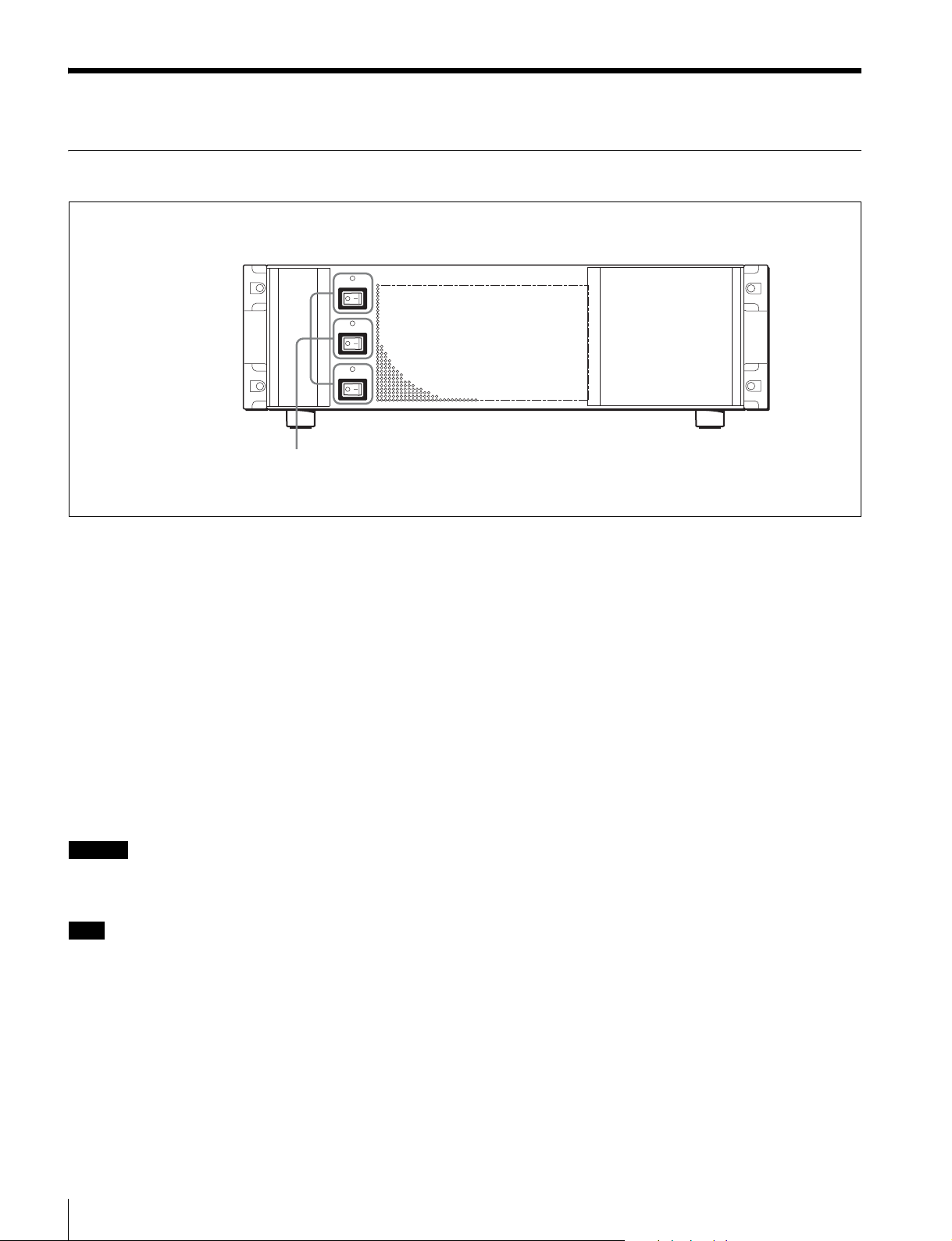
MFS-2000 Front Panel
POWER A
POWER B
POWER C
Power A, B, C switches and status indicator
POWER A, B and C switches and status indicators
The POWER switches turn the unit on and off. The unit is
powered on when the POWER switches are on the “?” side,
and powered off when the POWER switches are on the
“a” side. The status indicators light in green when the unit
is powered on.
Depending on the system’s configuration when shipped,
there may be no optional HK-PSU02 Power Supply Units
installed. In this case, the only available POWER switches
are A and B (there is no switch C).
The unit is not powered on until two of the POWER
switches (A, B and C) are turned on.
With HK-PSU02 units installed, the system continues to
function normally as long as any two of the power supply
units are operating normally.
Caution
When installing the HK-PSU02 in your unit, be sure to
contact your Sony service representative.
Note
If a status indicator does not light when you turn a POWER
switch on, there may be a fault in the power circuits. Turn
the POWER switch off and contact your Sony service
representative.
Location and Function of Parts
8
Page 9

MFS-2000 Rear Panel
C
1REF IN connectors
2REF OUT connector
3SWITCHER DATA connector
4DME DATA connector
5SWITCHER CTRL connector
6DME CTRL connector
7TERMINAL connector
8EDITOR connector
9SERIAL TALLY connector
0GPI connector
qaTally connector
DATA CTRL
REF OUT
DATA CTRL
REF IN
1
8
1 2 3 4 5 6 7 8 21 3 4
9
18
1 2 3 4 5 6 7 8 21 3 4
IN
IN
FM DATA
TERMINAL
EDITOR
SERIAL TALLY GPI
I.LINK S400
FM DEVICE
qgOUT 1 to 8 connectors
qhFM DATA connector
qjIN 1 to 16 connectors
a REF IN (reference signal input) connectors (BNC
type)
If you with to synchronize this unit to an external reference
signal, input the reference signal. For an HDTV system,
input an HD tri-level sync signal, black burst signal, or
analog sync signal. For an SDTV system, input a black
burst signal or analog sync signal.
The two connectors have a loop-through configuration.
Signal input to one connector can be output from the other
connector. If you will not be using the loop-through
output, be sure to terminate the unused connector with the
supplied 75Ω terminator.
b REF OUT (reference video output) connector
(BNC type)
Output HD3 signals for HDTV and analog sync signals for
SDTV.
TALLY
OUT
OUT
- AC IN
- AC IN
U
qsU terminal
qd-AC IN A, B, C connectors
qfFM DEVICE connector
c SWITCHER DATA connector (RJ-45)
Connect to an Ethernet switch*.
The MFS-2000 System is connected in the same way to the
Ethernet switch to form a network for exchange of signals
between the devices. This network is used primarily for
exchange of various types of data (setup data, snapshots,
etc.).
* For information about Ethernet switches that can be used in an MFS-2000
system, contact your Sony service representative.
For more information about Ethernet switch connectors,
see “MFS-2000 System Configuration” (page 14).
For detailed information about setting up the Ethernet
switch, refer to the documentation supplied with the
Ethernet switch.
Location and Function of Parts
9
Page 10

d DME DATA (Digital Multi Effects Data) connector
(RJ-45)
Connect to an Ethernet switch.
The MFS-2000 System is connected in the same way to the
Ethernet switch to form a network for exchange of signals
between the devices.
The DME DATA connector is used to transfer data to
devices such as the MKS-2470.
e SWITCHER CTRL (Switcher Control) connector
(RJ-45)
Connect to an Ethernet switch.
The MFS-2000 System is connected in the same way to the
Ethernet switch to form a network for exchange of signals
between the devices.
This connector is used mainly for control from control
panels.
f DME CTRL (Digital Multi Effects Control)
connector (RJ-45)
Connect to an Ethernet switch.
The MFS-2000 System is connected in the same way to the
Ethernet switch to form a network for exchange of signals
between the devices.
The DME CTRL connector is used to control the MKS-
2470.
g TERMINAL connector (D-sub 9-pin, RS-232C)
This connector is used for factory adjustments.
h EDITOR connector (D-sub 9-pin, RS-422A)
Used to control the MFS-2000 AUX bus from external
devices, and to operate the MFS-2000 from editing control
systems such as the BVE-9100.
Specify the types of connected devices on the control
panel.
i SERIAL TALLY connector (D-sub 9-pin, RS-422A
compliant)
Outputs serial tally data.
j GPI (General Purpose Interface) connector (D-sub
25-pin)
Connect to external devices for input and output of trigger
signals. Up to eight inputs and eight outputs are possible,
with input and output connections set on the control panel.
m -AC IN (AC power input) A, B, C connectors (3-
pin)
Connect to 100 to 240 V AC power supply with the
optional AC power cords.
Depending on the system’s configuration when shipped,
there may be no optional HK-PSU02 Power Supply Unit
installed. In that case, the AC IN C connector is not used.
Note
For information about installing an HK-PSU02, contact
your Sony service representative.
n FM DEVICE connector (IEEE1394)
This connector is for attaching an external hard disk drive
for frame memory.
For details of hard disk drives that can be used, consult
your Sony service representative.
o OUT 1 to 8 connectors (BNC type)
These connectors output serial digital signals. They can be
freely assigned to program output, preview output, AUX
output and so on.
Connectors 1 to 4 are supplied in the standard
configuration. Installation of the MKS-2110M makes
connectors 5 to 8 available.
When the MKS-2110M is installed, connector 1 to 4 are in
the upper row, and connectors 5 to 8 are in the lower row.
Each output has two connectors.
Make output assignments using the control panel of the
MFS-2000.
Refer to the User’s Guide for information about signals
that may be assigned.
p FM DATA connector (RJ-45)
Connect to an Ethernet switch. This is a dedicated LAN
connector for image data.
q IN 1 to 16 connectors (BNC type)
These connectors accept up to 16 serial digital video signal
inputs. Connectors 1 to 8 are supplied in the standard
configuration. Installation of the MKS-2110M makes
connectors 9 to 16 available.
When the MKS-2110M is installed, connectors 9 to 16 are
in the upper row.
k Tally connector (D-sub 25-pin)
Up to eight inputs and eight outputs are possible, with
input and output connections set on the control panel.
l U (signal ground) terminal
Connect to the system ground.
Location and Function of Parts
10
CAUTION
• When you connect the SWITCHER DATA connector,
DME DATA connector, SWITCHER CTRL connector,
DME CTRL connector and FM DATA connector of the
unit to peripheral devices, use a shielded-type cable to
prevent malfunction due to radiation noise.
Page 11

• For safety, do not connect the connector for peripheral
device wiring that might have excessive voltage to the
following ports.
- SWITCHER DATA connector
- DME DATA (Digital Multi Effects Data) connector
- SWITCHER CTRL (Switcher control) connector
MKS-2010/2015/2017 Front Panel
1“Memory stick” slot
2“Memory stick” status indicator
- DME CTRL (Digital Multi Effects Control)
connector
- FM DATA connector
Follow the instructions for the above ports.
3POWER A and B status indicators
A POWER B
a “Memory stick” slot
A slot to insert “Memory Stick”. Used to install software
and to save and read data such as snapshot and setup data.
See “About “Memory Stick”” (page 17) for more
information about “Memory Stick”.
b “Memory stick” status indicator
Data is being read from or written to a “Memory Stick”
when the status indicator is lit or flashing.
Note
Do not power the unit off or remove a “Memory Stick”
when the status indicator is lit or flashing.
c POWER A and B status indicators
The status indicators light in green when the unit is
powered on.
The POWER B status indicator does not light when the
optional HK-PSU11 Power Supply Unit is not supplied in
the factory configuration.
4USB connector
When the HK-PSU11 is installed, operation can be
continued as long as the POWER B status indicator is lit.
Caution
Contact a Sony service or marketing representative
regarding installation of the HK-PSU11.
Note
If the status indicators do not light even though the AC
power cord is connected, there may be failure in the unit.
Disconnect the AC power cord and contact a Sony service
or marketing representative.
d USB connector (USB Type A)
Connect a mouse, keyboard, pen tablet or other device
with a USB interface.
Note
Contact a Sony service or marketing representative for
more information about connectable devices.
Location and Function of Parts
11
Page 12

MKS-2010/2015/2017 Rear Panel
1 - AC IN A and B connectors
A
U
8DEVICE connector
9DATA connector
0EXT DISPLAY connector
qaU terminal
a - AC IN (AC power input) A and B connectors
(3-pin)
Connect to 100 to 240 V AC power supply with the
optional AC power cords.
There is not B connector when the optional HK-PSU11
Power Supply Unit is not installed.
Caution
Contact a Sony service or marketing representative
regarding installation of the HK-PSU11.
REF IN REMOTE
6REF IN connectors
7EDITOR PANEL connector
CTRL PERIPHEXT DISPLAY EDITOR PANELDEVICEDATA GPI
2GPI connector
3PERIPH connector
4CTRL connector
5REMOTE connector
c PERIPH (peripheral) connector (RJ-45)
Connect to the DCU-8000 Device Control Unit Pack with
a cross cable to enable communications with the DCU-
8000.
Note
An Ethernet switch is required to connect two or more
DCU-8000 Device Control Units.
b GPI (General Purpose Interface) connector
(D-sub 25-pin)
Connect to external devices for input and output of trigger
signals. Up to eight inputs and eight outputs are possible,
with input and output conditions set on the control panel.
Location and Function of Parts
12
Page 13

d CTRL (control) connector (RJ-45)
Connect the MFS-2000 to a network via the CTRL
connector and an Ethernet switch*.
* For information about Ethernet switches that can be used in an MFS-2000
system, contact your Sony service representative.
For more information about Ethernet switch connectors,
see “MFS-2000 System Configuration” (page 14).
For detailed information about setting up the Ethernet
switch, refer to the documentation supplied with the
Ethernet switch.
i DATA connector (RJ-45)
Connect the MFS-2000 to a network via the DATA
connector and an Ethernet switch.
This network is used primarily for the exchange of image
data from frame memory and various other types of data
(snapshots, etc.).
j EXT (extension) DISPLAY connector
(high-density D-sub 15-pin, analog RGB)
Connect an XGA compatible monitor to view edit data
pages.
e REMOTE connector (BNC type)
Connect this connector with a BNC cable to an S-BUS data
link via a T bridge.
An S-BUS data link is a single signaling circuit (S-BUS)
to which multiple devices can be connected to exchange
data.
Connecting devices such as HDS-X series routing
switchers and remote panels to an S-BUS data link enables
the following kinds of control.
• Returning to the S-BUS, tally data created by this unit on
the basis of data received from other devices
• Switching the cross-points of a switcher from the remote
panel
f REF IN (reference signal input) connectors
(BNC type)
If you wish to synchronize this unit to an external reference
signal, input the reference signal. For an HDTV system,
input an HD tri-level sync signal, black burst signal, or
analog sync signal. For an SDTV system, input a black
burst signal or analog sync signal.
The two connectors have a loop-through configuration.
Signal input to one connector can be output from the other
connector. If you will not be using the loop-through
output, be sure to terminate the unused connector with the
supplied 75Ω terminator.
Note
You cannot view edit data pages on the XGA compatible
monitor unless you have enabled a license for the BZS8050 Editing Control Software.
Refer to the User’s Guide for information about how to
enable your license.
k U (signal ground) terminal
Connect to the system ground.
CAUTION
• When you connect the PERIPH (peripheral) connector,
CTRL (control) connector and DATA connector of the
unit to peripheral devices, use a shielded-type cable to
prevent malfunction due to radiation noise.
• For safety, do not connect the connector for peripheral
device wiring that might have excessive voltage to the
following ports.
- PERIPH (peripheral) connector
- CTRL (control) connector
- DATA connector
Follow the instructions for the above ports.
g EDITOR PANEL connector (D-sub 15-pin,
RS-422A)
Connect a MKS-8050/2050 Editing Keyboard to this
connector.
Note
When you have connected a MKS-8050/2050 Editing
Keyboard to the EDITOR PANEL connector, do not
disconnect and connect the connector.
h DEVICE connector (USB Type A)
Connect devices with a USB interface, such as mice,
keyboards, and pen tablets.
Note
Contact a Sony service or marketing representative for
more information about devices which can be connected.
Location and Function of Parts
13
Page 14
Example System Configuration
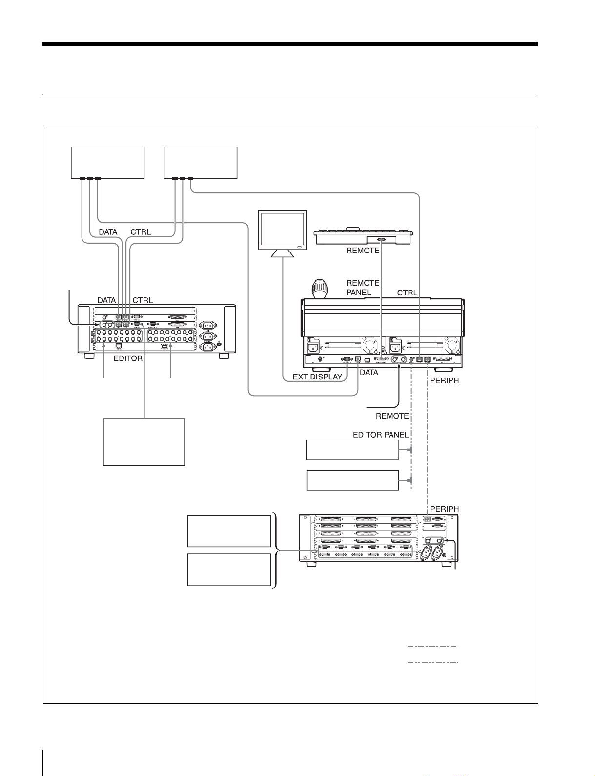
MFS-2000 System Configuration
Ethernet switch
Reference
video signal
Material video signal
(camera/VTR etc.)
b)
BVE-9100 Editing
Control System
a)
Ethernet switch
MFS-2000 Multi
Format Switcher
Processor
Output video signal
(Main line output/REC
VTR/Monitor etc.)
a)
XGA compatible monitor
c)
Reference video signal
MKS-2050/8050 Editing
Keyboard
BKS-R Series
d)
b)
MKS-2010/2015/
2017 Control Unit
a) It is recommended that the CTRL and DATA
LAN networks be configured by connecting
separate Ethernet switches for each LAN.
Depending on the type of Ethernet network,
a single Ethernet switch can perform
comparably to multiple switches.
For details, refer to the documentation of your
Ethernet switch.
Example System Configuration
14
HDS-X Series
DCU-8000 Device Control Unit Pack
VTR
DDR
b) Terminate with the supplied 75Ω
terminators. Terminators are supplied in the
product package.
c) This unit provides two output connectors for
each output. If you will be using only one of
the connectors, terminate the other with a 75
W terminator. Terminators are not supplied
with the unit.
d) The figure shows the MKS-2050.
Reference video
b)
signal
Cross cable
Cable with BNC
connectors
Page 15

Exchanging Button Labels
A button top puller is supplied with the control panel.
After changing a pattern assigned to a numeric button, you
can use the following procedure to exchange the button
label.
1
Write the new pattern on one of the supplied exchange
labels.
2
Grip the holes on the button sides with the supplied
button top puller and remove the button.
3
Reverse the button, grasp the outer sides of the cap
with the button puller, and remove the old label.
4
Remove the old label and insert the new label.
5
Replace the button cap.
6
Replace the button in its original location.
Adjusting Fader Torque
You can adjust faders without removing them from the
center control panel or operation modules.
Proceed as follows to adjust faders.
Hexagonal wrench
Fader lever
1
Pull the fader lever to an upright position between the
two holes on the fader cover.
2
Insert a hexagonal screwdriver or a hexagonal wrench
(4 mm sides) into one or both of the holes and rotate
to adjust the torque.
Rotate clockwise:
Fader lever operation becomes firmer.
23
Rotate counterclockwise:
Fader lever operation becomes freer.
Exchanging Button Labels / Adjusting Fader Torque
15
Page 16

Power Supply Unit Status
Control Panel Status
Indicators
The power supply unit status indicators show the status of
the power supply unit during operation and when the MFS2000 is powered on. Whenever a power error is detected,
it is reflected immediately by the indicator.
Meaning of status indicator displays
Indicator
color
Green Lit Operating normally −
Red Lit Power supply unit fan
− Not lit Power supply unit
Notes
• When the unit is powered on, the status indicators may
light momentarily in red and a whining sound may be
heard. This is not a malfunction.
• Power all of the installed power supply units on. When
some of the power supply units are off and some are on,
the status indicators of the units which are off may light
in red. This is not a malfunction.
Status Description Steps to take
fault
fault
Exchange the
fan unit
Exchange the
power unit
Indicators
The Control Panel status indicators show the status of the
power supply unit during operation and when the MKS2010/2015/2017 is powered on.
Meaning of status indicator displays
Indicator
color
Green Lit Operating normally −
− Not lit Power supply unit
Caution
Contact a Sony service or marketing representative before
exchanging a power supply unit, or exchanging the fan unit
in the power supply unit.
Status Description Steps to take
fault
Exchange the
power supply
unit
Caution
Contact a Sony service or marketing representative before
exchanging a power supply unit, or exchanging the fan unit
in the power supply unit.
Power Supply Unit Status Indicators / Control Panel Status Indicators
16
Page 17

Maintenance
About “Memory Stick”
Clean the menu display screen (touch screen) with a soft
cloth lightly moistened with ethanol.
Be sure to wipe only the dirty places lightly, taking care
not to spread the dirt. Moistening the cloth with too much
ethanol may also result in spreading the dirt.
A lens cleaning cloth may be useful to clean the screen.
Notes
• Do not use liquid other than ethanol to clean the screen.
• Be careful not to drip ethanol between the screen and the
body while cleaning.
• Wiping the screen with excessive force may scratch the
surface.
For details of the menu display, refer to the User’s Guide.
What is “Memory Stick” media?
“Memory Stick” is a compact, portable and versatile IC
(Integrated Circuit) recording medium with a data capacity
that exceeds that of a floppy disk. “Memory Stick” is
specially designed for exchanging and sharing digital data
among “Memory Stick”-compatible products. Because it
is removable, “Memory Stick” can also be used for
external data storage.
“Memory Stick” is available in three sizes: standard size,
compact “Memory Stick Duo”, “Memory Stick PRO-HG
Duo”, “MagicGate Memory Stick Duo” and “Memory
Stick Micro” size.
Available types of “Memory Stick”
• You can use “Memory Stick”, “Memory Stick PRO”,
“MagicGate Memory Stick”, “Memory Stick Duo”,
“Memory Stick PRO Duo”, “Memory Stick PRO-HG
Duo”, “MagicGate Memory Stick Duo” and “Memory
Stick Micro” media on this unit.
• When using a “Memory Stick Duo”, be sure to use it
with a “Memory Stick Duo Adaptor” (MSAC-M2 or
equivalent). If you insert a “Memory Stick Duo” without
using the adaptor, there is the possibility that the stick
cannot be removed, resulting in a serious accident.
• When using a “Memory Stick Micro”, be sure to use it
with a “Memory Stick Micro Adaptor” (MSAC-MMDS
or equivalent). If you insert a “Memory Stick Micro”
without using the adaptor, there is the possibility that the
stick cannot be removed, resulting in a serious accident.
• Data displayed on this unit is not protected by
MagicGate copyright protection technology because this
unit does not support the MagicGate standard.
• Although an operation check of this product has been
performed with a “Memory Stick” of up to 16 GB, please
note that operation is not guaranteed for every type of
“Memory Stick”.
Note on data read/write speed
Data read/write speed may vary depending on the
combination of the “Memory Stick” and “Memory Stick”
compliant product you use.
What is MagicGate?
MagicGate is copyright protection technology developed
by Sony Corporation.
Maintenance / About “Memory Stick”
17
Page 18

Before using a “Memory Stick”/“Memory
Stick PRO”/“MagicGate Memory Stick”
Terminal
Write-protect tab
Labeling position
Rear Front
Before using a “Memory Stick Duo”/
“Memory Stick PRO Duo”/“Memory Stick
PRO-HG Duo”/“MagicGate Memory Stick
Duo”
Terminal
Use an object with
a pointed end to
set the switch.
Write-protect tab
Rear Front
Before using a “Memory Stick Micro”
Attach the “Memory Stick Micro adaptor” to the “Memory
Stick Micro” to insert into the slot of the controller.
• Do not use or store the “Memory Stick” in a location that
is:
- Extremely hot, such as in a car parked in the sun
- Under direct sunlight
- Very humid or subject to corrosive substances
• When you use “Memory Stick Duo”/“Memory Stick
PRO Duo”/“Memory Stick PRO-HG Duo”/“MagicGate
Memory Stick Duo” with this product, be sure to insert
it in the right direction. Inserting it in the wrong direction
may cause damages to the product.
• “Memory Stick Duo”/“Memory Stick PRO Duo”/
“Memory Stick PRO-HG Duo” / “MagicGate Memory
Stick Duo”/“Memory Stick Micro” and “Memory Stick
Micro adaptor” should be kept away from small children
to prevent them from accidentally swallowing it.
• If the “Memory Stick Micro” attached to the “Memory
Stick Micro adaptor” is attached to the “Memory Stick
Duo adaptor” and inserted in the slot, the “Memory Stick
Micro” may not function.
• When it is shipped, a “Memory Stick” is formatted in a
special standard format. If you need to format a
“Memory Stick” yourself, format it on this unit.
• A “Memory Stick” that has been formatted on a
computer must be formatted again on this unit before it
can be used on this unit. Note that all data on the
“Memory Stick” is erased when it is reformatted. See the
User’s Guide for more information about the “Memory
Stick” format of this unit.
• Unauthorized recording may be contrary to the
provisions of copyright law. Copyright law forbids the
use of audio and video that you record without the
permission of the copyright holder for any purpose
except personal enjoyment. “Memory Stick” media that
contains copyrighted images or data cannot be used for
any purpose outside the range allowed by copyright law.
Notes
• You cannot record or erase data when the write-protect
tab on the “Memory Stick” is set to LOCK.
• Image data may be damaged in the following cases:
- If you remove the “Memory Stick”, or turn the power
off when the access lamp is lit or flashing
- If you use a “Memory Stick” near static electricity or a
magnetic field
• When writing on the memo area, do not apply overly
strong pressure with the pen.
• We recommend backing up important data.
• Do not attach anything other than the supplied label to
the “Memory Stick” labeling position.
• Attach the label so that it does not stick out beyond the
labeling position.
• Carry and store the “Memory Stick” in its case.
• Do not touch the connector of the “Memory Stick” with
anything, including your finger or metallic objects.
• Do not strike, bend, or drop the “Memory Stick”.
• Do not disassemble or modify the “Memory Stick”.
• Do not allow the “Memory Stick” to get wet.
About “Memory Stick”
18
“Memory Stick”, “Memory Stick PRO”, “MagicGate
Memory Stick”, “Memory Stick Duo”, “Memory Stick
PRO Duo”, “Memory Stick PRO-HG Duo”, “MagicGate
Memory Stick Duo”, “Memory Stick Micro”, “M2” and
are trademarks or registered trademarks of Sony
Corporation.
Page 19

Specifications
The following specifications show the reference
performance for this unit and individual option boards/
units.
Design and specifications are subject to change without
notice.
MFS-2000 Multi Format Switcher Processor
General
Power requirements
100 to 240 V AC, 50/60 Hz
Power consumption
100 V: 4.5 A, 240 V: 2.1 A
Peak inrush current
(1) Power ON, current probe method:
12 A (100 V), 33 A (240 V)
(2) Hot switching inrush current,
measured in accordance with
European standard EN55103-1: 22 A
(230 V)
Operating temperature
5ºC to 40ºC (41ºF to 104ºF)
Performance guaranteed temperature
10ºC to 35ºC (50ºF to 95ºF)
Storage temperature
−20ºC to +60ºC (−4ºF to +140ºF)
Operating humidity
10% to 90%
Dimensions (w/h/d, excluding projections)
482×132.4×520 mm
Mass Approx. 22 kg (48 lb 8 oz)
Input
Inputs 8 (BNC type)
Signal format SMPTE292M/SMPTE259M-C
Signal level 0.8 V p-p ±10%
Signal transfer rate
1.5 Gbps/270 Mbps
Return loss 15 dB
Cable length HDTV: 100 m (5C-FB cable,
SDTV: 200 m (5C-2V cable,
1
(19×5
/4×201/2 inches)
(when equipped with all installable
option boards and option power supply
unit)
BELDEN1694 or equivalent)
BELDEN8281 or equivalent)
Output
Outputs 4 (BNC type), each with 2 outputs
Signal format SMPTE292M/SMPTE259M-C
Signal level 0.8 V p-p ±10%
Signal transfer rate
1.5 Gbps/270 Mbps
Remote control connectors
CTRL RJ-45
Complies with 100Base-TX standard
DATA RJ-45
Complies with 100Base-TX standard
EDITOR, SERIAL TALLY
D-sub 9-pin, female
Comply with RS-422A standard
Data transfer rate: 38.4 Kbps
GPI D-sub 25-pin, female
TTL inputs: 8
Relay contact outputs: 4 (30 V AC/DC,
0.1 A)
Open collector outputs: 4
TALLY D-sub 25-pin, female
Relay contact outputs: 4 (30 V AC/DC,
0.1 A)
Open collector outputs: 4
TERMINAL D-sub 9-pin, female
Complies with RS-232C standard
Data transfer rate: 9600 bps
Reference input and output
IN BNC type, 75Ω with loop-through output
HDTV systems:
HD tri-level sync/SDTV analog black
burst/SDTV analog sync
SDTV systems:
Analog black burst/analog sync
OUT BNC type, 75Ω
HD tri-level sync (HDTV systems only)
Signal level 300 mV ±10%
Analog sync
Signal level 300 mV ±10%
Phase variation range
−90H to +90H
AC input
AC IN A, B, C
3-pin AC connector
Accessories supplied
75Ω terminator (1)
Operation Manual (1)
Installation Manual (1)
Specifications
19
Page 20

Accessories not supplied
AC power cord (for USA and Canada only) (125 V 10 A
2.4 m (8 ft)) (Part No.: 1-557-377-11)
AC power cord (for Europe only) (250 V 10 A 2.4 m
(8 ft)) (Part No.: 1-782-929-22)
MKS-2010 1 M/E Control Panel
GPI D-sub 25-pin, female
TTL inputs: 8
Relay contact outputs: 4 (30 V AC/DC,
0.1 A)
Open collector outputs: 4
EDITOR PANEL
D-sub, 15-pin, female
Complies with RS-422A standard
Data transfer rate: 38.4 Kbps
General
Power requirements
100 to 240 V AC, 50/60Hz
Power consumption
100V: 1.0A, 240V: 0.5A
Peak inrush current
(1) Power ON, current probe method:
12 A (100 V), 28 A (240 V)
(2) Hot switching inrush current,
measured in accordance with
European standard EN55103-1: 15 A
(230 V)
Operating temperature
5ºC to 40ºC (41ºF to 104ºF)
Performance temperature
10ºC to 35ºC (50ºF to 95ºF)
Storage temperature
−20ºC to +60ºC (−4ºF to +140ºF)
Operating humidity
10% to 90%
Dimensions (w/h/d)
440×102×353 mm (17
inches)
Mass Approx. 10.3 kg (22 lb 11 oz)
3
/8×41/8×14
Reference input
REF IN BNC type, 75Ω, with loop-through
output
HDTV systems:
HD tri-level sync/SDTV analog black
burst/SDTV analog sync
SDTV systems:
Analog black burst/analog sync
Control connectors
CTRL RJ-45
Complies with 100Base-TX standard
DATA RJ-45
Complies with 100Base-TX standard
PERIPH RJ-45
Complies with 100Base-TX standard
DEVICE USB Type A
Maximum supply current 400 mA
REMOTE BNC type, 75Ω
S-BUS
Data transfer rate: 312/1250 Kbps
Video output
EXT DISPLAY
High-density D-sub 15-pin, female
Analog RGB
AC input
AC IN A, B 3-pin AC connector
Accessories supplied
75Ω terminator (1)
T bridge (1)
Button top puller (1)
Self-lighting switch chip (5)
Fader adjustment tool (1)
White switch cap (9)
Mounting tool (1)
Software Licence Agreement (1)
Accessories not supplied
AC power cord (for USA and Canada only) (125 V 10 A
2.4 m (8 ft)) (Part No.: 1-557-377-11)
AC power cord (for Europe only) (250 V 10 A 2.4 m (8 ft))
(Part No.: 1-782-929-22)
MKS-2015 1.5 M/E Control Panel
General
Power requirements
100 to 240 V AC, 50/60Hz
Power consumption
100V: 1.0A, 240V: 0.5A
Peak inrush current
(1) Power ON, current probe method: 12
A (100 V), 28 A (240 V)
(2) Hot switching inrush current,
measured in accordance with
European standard EN55103-1: 15 A
(230 V)
Operating temperature
5ºC to 40ºC (41ºF to 104ºF)
Performance temperature
10ºC to 35ºC (50ºF to 95ºF)
20
Specifications
Page 21

Storage temperature
−20ºC to +60ºC (−4ºF to +140ºF)
Operating humidity
10% to 90%
Dimensions (w/h/d)
440×102×446 mm (17
inches)
Mass Approx. 11.3 kg (24 lb 15 oz)
3
/8×41/8×175/8
Reference input
REF IN BNC type, 75Ω, with loop-through
output
HDTV systems:
HD tri-level sync/SDTV analog black
burst/SDTV analog sync
SDTV systems:
Analog black burst/analog sync
Control connectors
CTRL RJ-45
Complies with 100Base-TX standard
DATA RJ-45
Complies with 100Base-TX standard
PERIPH RJ-45
Complies with 100Base-TX standard
DEVICE USB Type A
Maximum supply current 400 mA
REMOTE BNC type, 75Ω
S-BUS
Data transfer rate: 312/1250 Kbps
GPI D-sub 25-pin, female
TTL inputs: 8
Relay contact outputs: 4 (30 V AC/DC,
0.1 A)
Open collector outputs: 4
EDITOR PANEL
D-sub, 15-pin, female
Complies with RS-422A standard
Data transfer rate: 38.4 Kbps
White switch cap (9)
Mounting tool (1)
Software Licence Agreement (1)
Accessories not supplied
AC power cord (for USA and Canada only) (125 V 10 A
2.4 m (8 ft)) (Part No.: 1-557-377-11)
AC power cord (for Europe only) (250 V 10 A 2.4 m (8 ft))
(Part No.: 1-782-929-22)
MKS-2017 1.5 M/E Wide Control Panel
General
Power requirements
100 to 240 V AC, 50/60Hz
Power consumption
100V: 1.0A, 240V: 0.6A
Peak inrush current
(1) Power ON, current probe method: 12
A (100 V), 28 A (240 V)
(2) Hot switching inrush current,
measured in accordance with
European standard EN55103-1: 15 A
(230 V)
Operating temperature
5ºC to 40ºC (41ºF to 104ºF)
Performance temperature
10ºC to 35ºC (50ºF to 95ºF)
Storage temperature
–20ºC to +60ºC (–4ºF to +140ºF)
Operating humidity
10% to 90%
Dimensions (w/h/d)
592×102×446 mm (23
inches)
Mass Approx. 12.6 kg (27 lb 12 oz)
3
/8×41/8×175/8
Video output
EXT DISPLAY
High-density D-sub 15-pin, female
Analog RGB
AC input
AC IN A, B 3-pin AC connector
Accessories supplied
75Ω terminator (1)
T bridge (1)
Button top puller (1)
Self-lighting switch chip (5)
Fader adjustment tool (1)
Reference input
REF IN BNC type, 75Ω, with loop-through
output
HDTV systems:
HD tri-level sync/SDTV analog black
burst/SDTV analog sync
SDTV systems:
Analog black burst/analog sync
Control connectors
CTRL RJ-45
Complies with 100Base-TX standard
DATA RJ-45
Complies with 100Base-TX standard
Specifications
21
Page 22

PERIPH RJ-45
Complies with 100Base-TX standard
DEVICE USB Type A
Maximum supply current 400 mA
REMOTE BNC type, 75Ω
S-BUS
Data transfer rate: 312/1250 Kbps
GPI D-sub 25-pin, female
TTL inputs: 8
Relay contact outputs: 4 (30 V AC/DC,
0.1 A)
Open collector outputs: 4
EDITOR PANEL
D-sub, 15-pin, female
Complies with RS-422A standard
Data transfer rate: 38.4 Kbps
Video output
EXT DISPLAY
High-density D-sub 15-pin, female
Analog RGB
AC input
AC IN A, B 3-pin AC connector
MKS-2110M Input/Output Connector Board
General
Power requirements
12 V DC
Power consumption
Max. 10 W
Dimensions (w/d)
274×94 mm (10
Mass Approx. 1 kg (2 lb 3 oz)
Input
Inputs 8 (BNC type)
Signal format SMPTE292M/SMPTE259M-C
Signal level 0.8 V p-p ±10%
Signal transfer rate
1.5 Gbps/270 Mbps
Return loss 15 dB
Cable length HDTV: 100 m (5C-FB cable,
BELDEN1694 or equivalent)
SDTV: 200 m (5C-2V cable,
BELDEN8281 or equivalent)
7
/8×33/4 inches)
Accessories supplied
75Ω terminator (1)
T bridge (1)
Button top puller (1)
Self-lighting switch chip (5)
Fader adjustment tool (1)
White switch cap (9)
Mounting tool (1)
Software Licence Agreement (1)
Accessories not supplied
AC power cord (for USA and Canada only) (125 V 10 A
2.4 m (8 ft)) (Part No.: 1-557-377-11)
AC power cord (for Europe only) (250 V 10 A 2.4 m (8 ft))
(Part No.: 1-782-929-22)
Output
Outputs 4 (BNC type), each with 2 outputs
Signal format SMPTE292M/SMPTE259M-C
Signal level 0.8 V p-p ±10%
Signal transfer rate
1.5 Gbps/270 Mbps
Accessories supplied
Operation and Installation Guide (1)
(supplied only when product is purchased separately)
MKS-2420M Color Corrector Board
Power requirements
3.3 V DC + 1.5 V DC
Power consumption
Max. 30 W
Dimensions (w/d)
80×150 mm (3
Mass 0.5 kg (1 lb 1 oz)
Accessories supplied
Operation and Installation Guide (1)
(supplied only when product is
purchased separately)
1
/4×6 inches)
22
Specifications
Page 23

MKS-2440 Frame Memory Board Set
HK-PSU11 Power Supply Unit
Power requirements
12 V DC
Power consumption
Max. 100 W
Dimensions (w/d)
MY-112 board: 317×380 mm (12
inches)
CN-2535 board: 279×94 mm (11×3
inches)
Mass Approx. 2 kg (4 lb 6 oz)
Output
FM DATA RJ-45, complies with 100Base-TX
standard
FM DEVICE Complies with IEEE1394 6-pin
Accessories supplied
Operation and Installation Guide (1)
(supplied only when product is
purchased separately)
MKS-2470 DME Board Set
Power requirements
12 V DC
Power consumption
Max. 100 W
Dimensions (w/d)
DVP board: 317×380 mm
1
(12
/2×15 inches)
CA board: 317×380 mm
1
(12
/2×15 inches)
Mass Approx. 4 kg (8 lb 13 oz)
Accessories supplied
Operation and Installation Guide (1)
(supplied only when product is
purchased separately)
1
/2×15
3
/4
Operating temperature
+5°C to +40°C (+41°F to +104°F)
Storage temperature
–20°C to +60°C (–4°F to +140°F)
Operating humidity
10 % to 90 % (no moisture condensation)
Dimensions (w/h/d, excluding projections)
204.8×43.2×119.2 mm (8
inches)
Mass Approx. 0.7 kg (1 lb 8 oz)
Accessories supplied
Installation Guide (1) (supplied only
when product is purchased separately)
1
/8×13/4×43/4
HK-PSU02 Power Supply Unit
Operating temperature
+5°C to +40°C (+41°F to +104°F)
Storage temperature
–20°C to +60°C (–4°F to +140°F)
Operating humidity
10 % to 90 % (no moisture condensation)
Dimensions (w/h/d, excluding projections)
94×40.1×393.1 mm (3
inches)
Mass Approx. 1.5 kg (3 lb 5 oz)
Accessories supplied
Installation Guide (1) (supplied only
when product is purchased separately)
3
/4×15/8×151/2
Specifications
23
Page 24

24
Specifications
Page 25

The material contained in this manual consists of information
that is the property of Sony Corporation and is intended solely
for use by the purchasers of the equipment described in this
manual.
Sony Corporation expressly prohibits the duplication of any
portion of this manual or the use thereof for any purpose other
than the operation or maintenance of the equipment described
in this manual without the express written permission of Sony
Corporation.
Page 26
Sony Corporation
MFS-2000-C
(SY)
3-855-583-04 (1)
Printed in Japan
2008.10.13
© 2004
 Loading...