

Page 1
MDR-SA1000/SA3000/SA5000
SERVICE MANUAL
Ver. 1.0 2005.02
Photo: MDR-SA5000
SPECIFICATIONS
MDR-SA1000/SA3000
Type
Open air, dynamic
Driver units
50 mm, (CCAW adopted), dome type
Power handling capacity
1,500 mW (IEC*)
Impedance
70 Ω at 1 kHz
Sensitivity
100 dB/mW
Frequency response
MDR-SA3000 : 8 − 100,000 Hz
MDR-SA1000 : 8 − 80,000 Hz
Cord
MDR-SA3000 : 3.5 m (11.5 ft), 6N-OFC litz cord
MDR-SA1000 : 3.5 m (11.5 ft), OFC litz cord
Plug
Gold-plated stereo mini plug
Mass
Approx. 265 g (9.3 oz) without cord
Supplied accessories
Operating Instructions (1), Warranty (1), Product Information
(MDR-SA3000 only) (1), Carrying porch (1), Gold-plated
unimatch plug adaptor
(stereo phone plug y stereo mini jack) (1)
* IEC = International Electrotechnical Commission
US Model
AEP Model
MDR-SA1000/SA3000/SA5000
Canadian Model
MDR-SA1000/SA3000
E Model
MDR-SA3000
MDR-SA5000
Type
Open air, dynamic
Driver units
50 mm, (CCAW adopted), dome type
Power handling capacity
1,500 mW (IEC*)
Impedance
70 Ω at 1 kHz
Sensitivity
102 dB/mW
Frequency response
5 Hz − 110 kHz
Cord
3.5 m (11.5 ft), 6-N OFC litz cord
Plug
Gold-plated stereo phone plug
Mass
Approx. 260 g (9.2 oz) without cord
Supplied accessories
Stand (1), Operating Instructions (1),
Warranty (1), Product Information (1)
* IEC = International Electrotechnical Commission
Design and specifications are subject to change without notice.
9-879-492-01
2005B05-1
© 2005.02
STEREO HEADPHONES
Sony Corporation
Personal Audio Company
Published by Sony Engineering Corporation
Page 2
MDR-SA1000/SA3000/SA5000
SECTION 1
DISASSEMBLY
Note: Follow the disassembly procedure in the numerical order given.
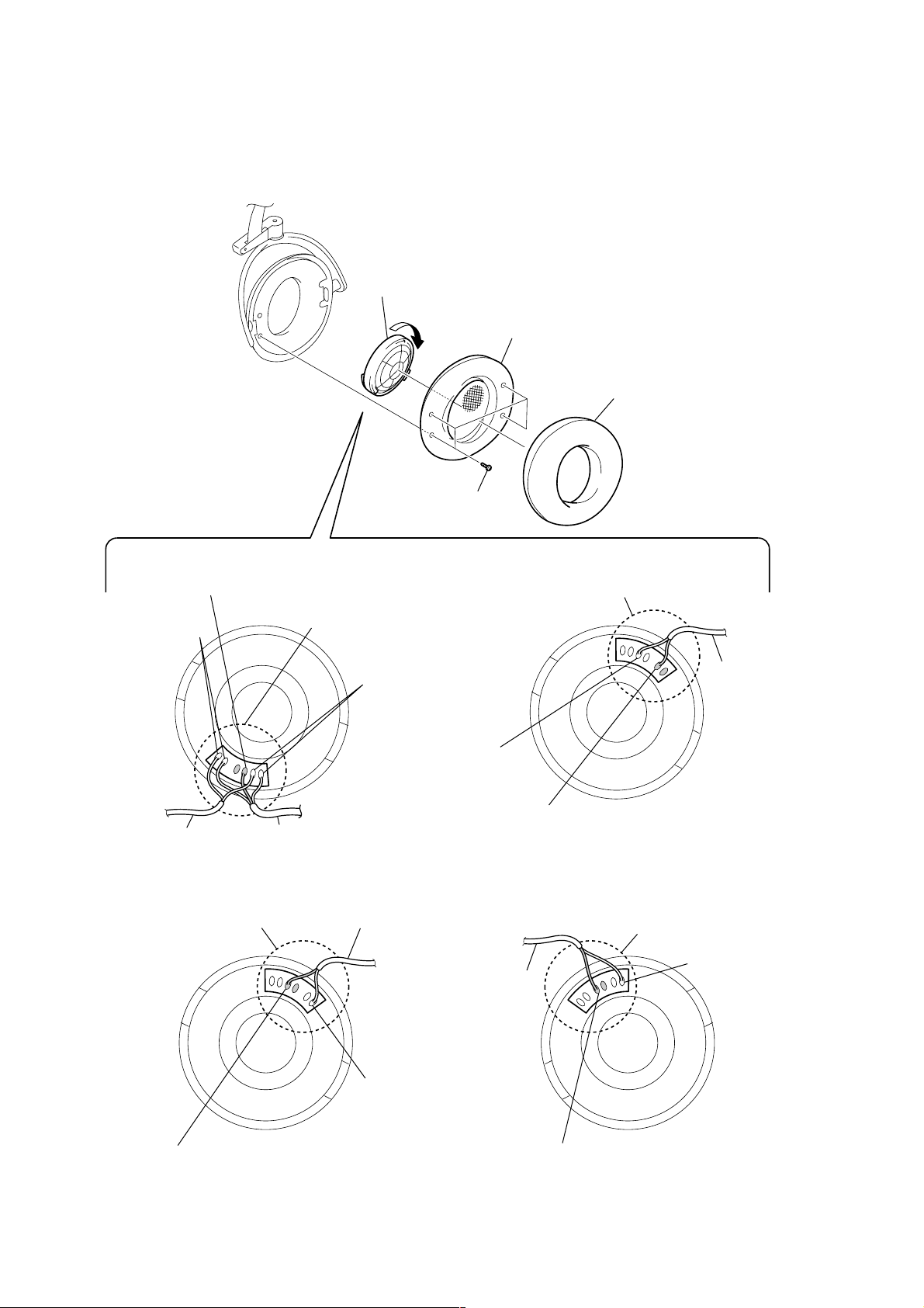
DRIVER (Lch/Rch)
(For both left and right headphones, disassemble through the same procedure)
4
Rotate the driver (Lch/Rch) in
the arrow direction to remove.
5
front plate assy
1
ear pad
Connect a lead wire of the cord (with plug) (green) to the terminal
with a marking.
(The location of a marking may differ from the illustration.)
3
Natural color lead wire
connecting locations
head band cord
3
Remove two solders
of the cord (with plug).
cord (with plug)
– DRIVER (Lch) –
(SA1000/SA3000)
Remove five solders of the head
band cord and cord (with plug).
Red color lead wire
connecting locations
Natural color lead wire
connecting locations
cord (with plug)
2
four screws
3
Remove two solders
of the head band cord.
head band cord
Connect a lead wire of the head band cord (red) to the terminal
with a marking.
(The location of a marking may differ from the illustration.)
– DRIVER (Rch) –
(SA1000/SA3000)
3
Remove two solders
of the cord (with plug).
Black color lead wire
cord (with plug)
connecting locations
Black color lead wire
connecting locations
Connect a lead wire of the head band cord (green) to the terminal
with a marking.
(The location of a marking may differ from the illustration.)
– DRIVER (Lch) –
(SA5000)
2
Connect a lead wire of the head band cord (red) to the terminal
with a marking.
(The location of a marking may differ from the illustration.)
– DRIVER (Rch) –
(SA5000)
Page 3
SECTION 2
EXPLODED VIEWS
MDR-SA1000/SA3000/SA5000
NOTE:
• -XX and -X mean standardized parts, so they
may have some difference from the original
one.
• Color Indication of Appearance Parts
Example:
KNOB, BALANCE (WHITE) . . . (RED)
↑↑
Parts Color Cabinet's Color
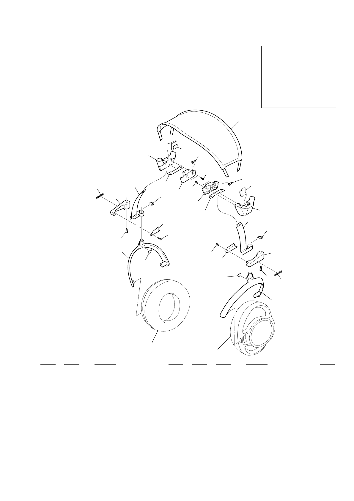
2-1. HEADBAND SECTION
(MDR-SA1000/SA3000)
21
6
3
• Items marked “*” are not stocked since they
are seldom required for routine service. Some
delay should be anticipated when ordering
these items.
• The mechanical parts with no reference
number in the exploded views are not supplied.
• Accessories are given in the last of the parts
list.
The components identified by mark
0 or dotted line with mark 0 are
critical for safety.
Replace only with part number
specified.
Les composants identifiés par une
marque 0 sont critiquens pour la
sécurité.
Ne les remplacer que par une pièce
portant le numéro spécifié.
11
10
9
3
14
3
7
12
8
13
14
10
15
12
5
16
17
8
4
1
2
housing (R) section
Ref. No. Part No. Description Remark
1 2-546-870-01 HANGER (R) (SA3000)
1 2-546-870-11 HANGER (R) (SA1000)
2 2-586-769-01 SEAL, HANGER
3 2-548-701-01 BUSHING (CORD)
4 3-254-070-11 SCREW
5 2-546-866-01 LID (R), HOLDER (SA3000)
5 2-546-866-11 LID (R), HOLDER (SA1000)
6 2-546-864-01 HOLDER (R) (SA3000)
6 2-546-864-11 HOLDER (R) (SA1000)
7 X-2050-496-1 SLIDER (R) ASSY
4
19
18
2
3
21
20
housing (L) section
Ref. No. Part No. Description Remark
13 2-546-862-01 LID (R), CLICK CASE (SA3000)
13 2-546-862-11 LID (R), CLICK CASE (SA1000)
14 3-253-143-01 SCREW (B2.6), (+) P TAPPING
15 2-546-861-01 LID (L), CLICK CASE (SA3000)
15 2-546-861-11 LID (L), CLICK CASE (SA1000)
16 2-546-859-01 CLICK CASE (L) (SA3000)
16 2-546-859-11 CLICK CASE (L) (SA1000)
17 X-2050-495-1 SLIDER (L) ASSY
18 2-546-865-01 LID (L), HOLDER (SA3000)
18 2-546-865-11 LID (L), HOLDER (SA1000)
8 2-548-700-01 RING, RETAINING
9 2-546-860-01 CLICK CASE (R) (SA3000)
9 2-546-860-11 CLICK CASE (R) (SA1000)
10 2-546-883-01 SPRING (CLICK)
11 X-2025-345-1 HEADBAND ASSY
12 2-549-692-01 RETAINER, BAND
19 2-546-863-01 HOLDER (L) (SA3000)
19 2-546-863-11 HOLDER (L) (SA1000)
20 2-546-869-01 HANGER (L) (SA3000)
20 2-546-869-11 HANGER (L) (SA1000)
21 3-032-552-01 EMBLEM (NO 2.5), SONY
3
Page 4

MDR-SA1000/SA3000/SA5000
2-2. HOUSING (R) SECTION (MDR-SA1000/SA3000)
(SA3000)
56
61
55
58
58
60
57
59
53
52
54
Ref. No. Part No. Description Remark
51 2-546-965-01 EARPAD
52 3-253-143-01 SCREW (B2.6), (+) P TAPPING
53 X-2025-344-1 PLATE (R) ASSY, FRONT (SA3000)
53 X-2055-042-1 PLATE (R) ASSY, FRONT (SA1000)
54 1-542-603-11 DRIVER (050F030) (SA3000)
54 1-542-604-11 DRIVER (050F031) (SA1000)
55 2-586-521-01 GRILLE BASE (R) (SA3000)
55 2-586-551-01 GRILLE BASE (R) (SA1000)
51
Ref. No. Part No. Description Remark
56 2-546-875-01 RING, ORNAMENTAL (SA3000)
57 2-546-885-01 SHEET, DRIVER
58 2-549-886-01 CAP, DUMMY (SA3000)
58 2-549-886-11 CAP, DUMMY (SA1000)
59 2-546-877-01 HOUSING
60 2-546-872-01 FRAME (R) (SA3000)
60 2-546-872-11 FRAME (R) (SA1000)
61 2-546-873-01 GRILLE
4
Page 5

2-3. HOUSING (L) SECTION (MDR-SA1000/SA3000)
MDR-SA1000/SA3000/SA5000
106
(SA3000)
109
108
101
102
103
111
105
107
113
112
104
Ref. No. Part No. Description Remark
101 2-546-965-01 EARPAD
102 3-253-143-01 SCREW (B2.6), (+) P TAPPING
103 X-2025-343-1 PLATE (L) ASSY, FRONT (SA3000)
103 X-2055-033-1 PLATE (L) ASSY, FRONT (SA1000)
104 1-542-603-11 DRIVER (050F030) (SA3000)
104 1-542-604-11 DRIVER (050F031) (SA1000)
105 2-546-880-01 BUSHING
106 2-546-885-01 SHEET, DRIVER
107 2-549-886-01 CAP, DUMMY (SA3000)
107 2-549-886-11 CAP, DUMMY (SA1000)
not supplied
110
Ref. No. Part No. Description Remark
108 2-546-874-01 GRILLE BASE (L) (SA3000)
108 2-549-727-01 GRILLE BASE (L) (SA1000)
109 2-546-875-01 RING, ORNAMENTAL (SA3000)
110 1-829-559-11 CORD (WITH PLUG) (SA3000)
110 1-829-560-11 CORD (WITH PLUG) (SA1000)
111 2-546-877-01 HOUSING
112 2-546-871-01 FRAME (L) (SA3000)
112 2-546-871-11 FRAME (L) (SA1000)
113 2-546-873-01 GRILLE
5
Page 6

MDR-SA1000/SA3000/SA5000
2-4. HEADBAND SECTION (MDR-SA5000)
164
155
154
153
163
156
160
161
157
159
158
162
162
161
160
159
165
163
168
156
169
166
157
152
151
housing (R) section
Ref. No. Part No. Description Remark
151 2-582-086-01 COVER, SCREW
152 2-025-589-01 SCREW, STEP
153 2-345-422-01 HANGER (R)
154 2-345-424-01 HOLDER (R)
155 X-2050-281-1 SLIDER ASSY (R)
167
152
151
housing (L) section
Ref. No. Part No. Description Remark
161 2-113-146-01 SPRING, COMPRESSION
162 2-345-551-01 CASE, CLICK
163 2-345-553-01 STOPPER, HEAD BAND
164 2-345-427-02 BAND, HEAD
165 X-2024-612-1 CUSHION ASSY, HEAD
156 7-624-106-04 STOP RING 3.0, TYPE -E
157 2-546-592-01 STOPPER, SLIDER
158 2-345-426-01 LID (R), HOLDER
159 3-254-149-01 SCREW (M1.7)
160 7-671-155-01 STEEL BALL 3.0
6
166 2-345-423-01 HOLDER (L)
167 2-345-421-01 HANGER (L)
168 X-2050-280-1 SLIDER ASSY (L)
169 2-345-425-01 LID (L), HOLDER
Page 7

2-5. HOUSING SECTION (MDR-SA5000)
202
210
MDR-SA1000/SA3000/SA5000
207
208
204
209
205
209
203
201
207
208
204
202
211
201
Ref. No. Part No. Description Remark
201 2-345-306-01 PAD, EAR
202 2-345-434-01 GUIDE, FINGER
203 3-245-709-11 SCREW
204 1-542-603-11 DRIVER (050F030)
205 1-829-942-11 CORD (WITH PLUG)
203
Ref. No. Part No. Description Remark
207 2-345-546-01 BUSHING
208 2-546-594-01 STOPPER, ROTARY
209 X-2050-674-1 PLATE ASSY, FRONT
210 X-2050-676-1 FRAME ASSY, (L)
211 X-2050-675-1 FRAME ASSY, (R)
7
Page 8

MDR-SA1000/SA3000/SA5000
ACCESSORIES
Ref. No. Part No. Description Remark
1-829-559-11 CORD (WITH PLUG) (SA3000)
1-829-560-11 CORD (WITH PLUG) (SA1000)
2-587-948-11 MANUAL, INSTRUCTION (ENGLISH, SPANISH)
2-587-948-21 MANUAL, INSTRUCTION (ENGLISH, FRENCH,
GERMAN, SPANISH, ITALIAN, PORTUGUES)
* 2-587-857-11 MANUAL, INSTRUCTION (ENGLISH, SPANISH)
2-587-857-21 MANUAL, INSTRUCTION (ENGLISH, FRENCH,
GERMAN, SPANISH, ITALIAN, PORTUGUES,
CZECH, HUNGARIAN, POLISH, RUSSIAN,
4-985-107-02 POUCH (SA1000/SA3000)
501 X-2050-282-1 STAND ASSY (SA5000)
502 2-583-980-01 FOOT (STAND) (SA5000)
(SA1000: US/SA3000: US)
(SA1000: Canadian, AEP/
SA3000: Canadian, AEP, E)
(SA5000: US)
SLOVAKIAN) (SA5000: AEP)
501
not supplied
502
502
STAND ASSY
8
Page 9

MEMO
MDR-SA1000/SA3000/SA5000
9
Page 10

MDR-SA1000/SA3000/SA5000
REVISION HISTORY
Clicking the version allows you to jump to the revised page.
Also, clicking the version at the upper right on the revised page allows you to jump to the next revised
page.
Ver. Date Description of Revision
1.0 2005.02 New
2
 Loading...