

Sony MDRNC-60 Service manual
MDR-NC60
SERVICE MANUAL
Ver. 1.0 2007.03
SPECIFICATIONS
General
Type Dynamic, closed
Driver units 40 mm, dome type (CCAW adopted)
Power handling capacity
Impedance 40 Ω at 1 kHz
Sensitivity 102 dB/mW
Frequency response
Frequency range of active noise attenuation
Power source DC 1.5 V, 1 × R03 (size AAA) battery
Mass
Supplied accessories
Connecting cord (0.5 m, gold plated stereo mini
plug)(1) (Tourist)
Connecting cord (1.5 m, gold plated L type stereo
mini plug)(1)
Sony R03 (size AAA) battery (1) (US, Tourist)
Carrying case (1)
Plug adapter for in-flight use* (single/dual)(1)
Gold-plated unimatch plug adapter (stereo phone
plug y stereo mini jack)(1)
Operating Instructions (1)
Card warranty (1) (Except E)
*May not be compatible with some in-flight
music services.
100 mW
(when the power is on)
100 Ω at 1 kHz
(when the power is off)
(when the power is on)
100 dB/mW
(when the power is off)
14 – 24,000 Hz
40 – 1,500 Hz, more than 16.5 dB at
200 Hz
Approx. 230 g (8 oz) including battery
US Model
Canadian Model
AEP Model
Tourist Model
Battery life
Battery
Sony alkaline LR03/AM-4
(N) (size AAA) battery
Sony manganese R03/ UM-4
(NU) (size AAA) battery
*11 kHz, 0.1 mW + 0.1 mW output
2
*
Time stated above may vary, depending on the
temperature or conditions of use.
Note
Because the supplied battery was included in the
package from the time of manufacture (as a
convenience to the user), it is possible that the
battery life may be somewhat depleted by the
time of purchase. The actual life of the supplied
battery may be shorter than the standard time
described in this manual when using a fresh
battery.
When to replace the battery
Replace the battery with a new one when the
POWER indicator dims. The noise canceling feature
may not work correctly if battery power is low.
Design and specifications are subject to change
without notice.
Approx. hours*
30 hours*
15 hours*
1
2
2
NOISE CANCELING
HEADPHONES
E Model
9-887-554-01
2007C05-1
© 2007.03
Sony Corporation
Personal Audio Division
Published by Sony Techno Create Corporation

MDR-NC60
UNLEADED SOLDER
Boards requiring use of unleaded solder are printed with the leadfree mark (LF) indicating the solder contains no lead.
(Caution: Some printed circuit boards may not come printed with
the lead free mark due to their particular size)
: LEAD FREE MARK
Unleaded solder has the following characteristics.
• Unleaded solder melts at a temperature about 40 ˚C higher
than ordinary solder.
Ordinary soldering irons can be used but the iron tip has to be
applied to the solder joint for a slightly longer time.
Soldering irons using a temperature regulator should be set to
about 350 ˚C.
Caution: The printed pattern (copper foil) may peel away if
the heated tip is applied for too long, so be careful!
• Strong viscosity
Unleaded solder is more viscou-s (sticky, less prone to flow)
than ordinary solder so use caution not to let solder bridges
occur such as on IC pins, etc.
• Usable with ordinary solder
It is best to use only unleaded solder but unleaded solder may
also be added to ordinary solder.
Note on chip component replacement
• Never reuse a disconnected chip componet
• Notice that the minus side of a teamtalum capacitor may be damaged by
heat
TABLE OF CONTENTS
1. GENERAL ................................................................... 3
2. DISASSEMBLY
2-1. Disassembly Flow ........................................................... 4
2-2. ML Board ........................................................................ 4
2-3. MR Board ........................................................................ 5
2-4. Head Band Assy .............................................................. 5
2-5. Hanger (L/R) ................................................................... 6
2-6. Housing Cap (L/R) .......................................................... 6
2-7. Position of Lead Wires .................................................... 7
3. ELECTRICAL ADJUSTMENT ............................ 8
4. DIAGRAMS
4-1. Block Diagram ................................................................ 13
4-2. Printed Wiring Boards – L-CH Section – ........................ 15
4-3. Schematic Diagram – L-CH Section – ............................ 16
4-4. Printed Wiring Boards – R-CH Section – ....................... 17
4-5. Schematic Diagram – R-CH Section –............................ 18
5. EXPLODED VIEWS
5-1. Housing Section .............................................................. 19
5-2. Head Band Assy Section ................................................. 20
6. ELECTRICAL PARTS LIST................................ 21
2
Features
• Noise canceling headphones reduce unwanted
ambient noise, providing a quieter environment
to enhance your listening experience. A
microphone inside each earpiece works with
electronic circuitry to create an opposite sound
wave to cancel out the noise. Up to 85 %
ambient noise cancellation (Over 16.5 dB is
reduced at 200 Hz)
• Slim, folding design for easy portability
• Neodymium magnets for powerful sound
• Dual-use capability allows option to listen to
music with or without noise cancellation
• Built-in monitor function lets you silence the
audio to listen outside
• Supplied plug adaptor for easy connectivity to
stereo or dual jack for in-flight music services
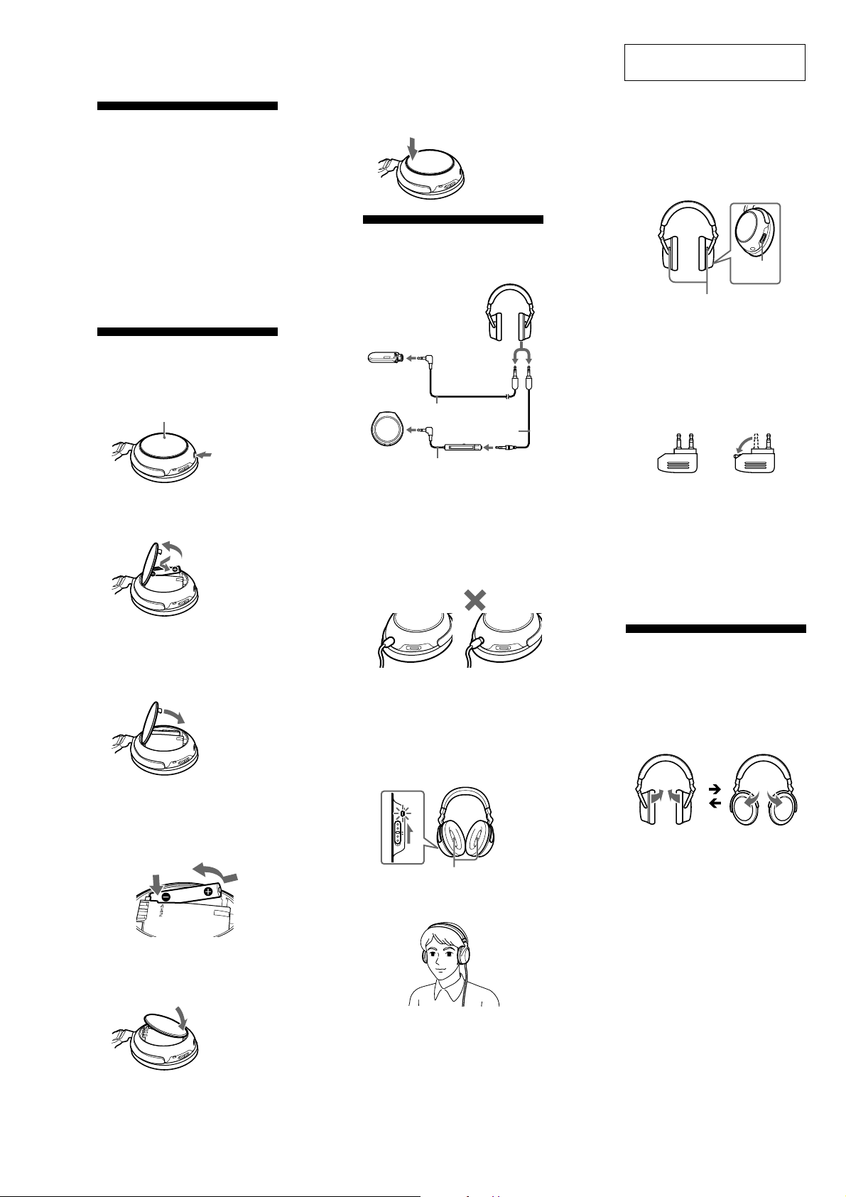
Installing a battery
1
Push the “BATT Z” button located at the
bottom of the right housing.
The lid of the battery box opens slightly.
Right housing
SECTION 1
GENERAL
2
Push the upper side of the lid straight
forward until it clicks into position.
Listening to music
1
Connect the headphones to the AV
equipment.
Headphones
When connecting to the
stereo mini jack of a
WALKMAN*, etc.
Connecting cord 1.5 m
(supplied)
Connecting cord 0.5 m
(supplied)
MDR-NC60
This section is extracted from
instruction manual.
4
Turn on the power of the AV equipment.
Hearing environmental sound for
safety
If the MONITOR switch is pressed and held
while the POWER switch is set to ON, playback
silences so you can hear the surrounding
environment.
LR
MONITOR
switch
Monitor microphone
LR
Note
The environmental sound might not be heard if
the microphone is covered with your fingers.
Notes on using on the
airplane
• The supplied plug adaptor can be connected to
dual and stereo mini jacks.
for dual jacks for stereo mini jacks
2
Open the lid of the battery box of the
headphone to insert one size AAA
battery.
1
2
Match the e on the
battery to the e in the
battery case.
Note
The lid of the battery box opens only so far,
as shown in the illustration. Do not further
force open the lid as it may damage it.
3
Close the lid.
To remove the battery
Open the lid of the battery box, then push the
position marked with “PUSH G”. The e side of
the battery comes up. Remove the battery by
pulling it.
1
2
When connecting to the stereo mini jack
of the remote control’s jack supplied with
a WALKMAN, etc.
*“WALKMAN” and “WALKMAN” logo are
registered trademarks of Sony Corporation.
Remote control
Notes
• When connecting the cord, insert the plug into
the jack until the green portion of the plug
disappears.
OK
•To disconnect the cord, pull it out by the plug,
not the cord, as the inner conductors may break.
2
Turn on the power on the right side of the
headphones.
The POWER indicator lights in red. When the
power is turned on, ambient noise is reduced,
and you can listen to music more clearly at a
lower volume.
POWER
OFFON
Noise canceling microphone
3
Put on the headphones so that the ear
pads cover your ears.
LR
• Do not use the headphones when use of
electronic equipment is prohibited or when use
of personal headphones for in-flight music
services is prohibited.
If you have any questions or problems concerning
the system that are not covered in this manual,
please consult the nearest Sony dealer.
After listening to music
Turn off the power of the headphones.
Folding the
headphones
Folding
The housings rotate to make them flat for easy
storage in the carrying case (supplied), or in a seat
pocket.
Restore to their usual position before using.
If the lid of the battery box is
detached
Follow the procedure below to reattach the lid.
1
Attach the lower side of the lid.
RL
3
MDR-NC60
y
• This set can be disassembled in the order shown below.
2-1. DISASSEMBLY FLOW
SET
SECTION 2
DISASSEMBLY
2-2. ML BOARD
(Page 4)
2-4. HEAD BAND ASSY
(Page 5)
2-5. HANGER (L/R)
(Page 6)
Note: Follow the disassembly procedure in the numerical order given.
2-3. MR BOARD
(Page 5)
2-6. HOUSING CAP (L/R)
(Page 6)
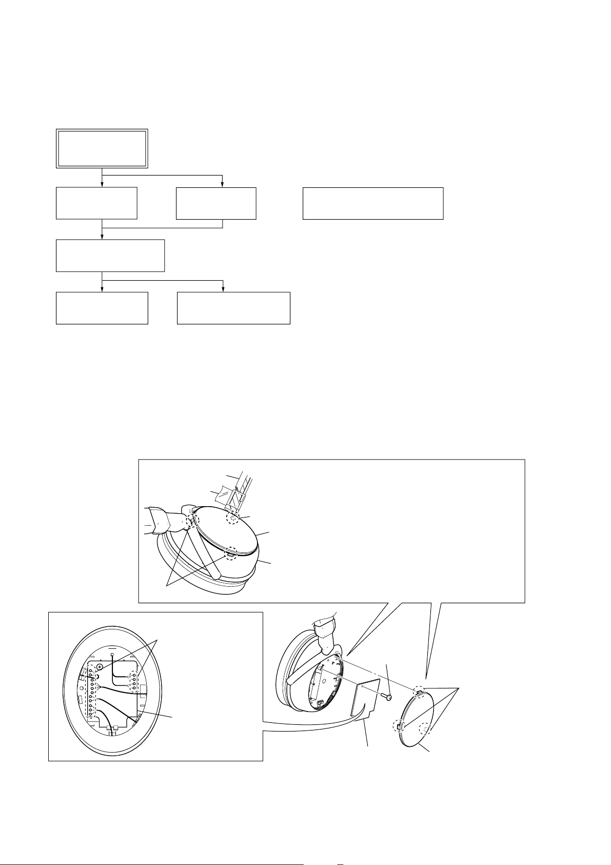
2-2. ML BOARD
cutter blade
tape
claw
2-7. POSITION OF LEAD WIRES
(Page 7)
1
Remove the ornament cap (L) assy by inserting a cutter blade,
etc. into a gap between housing cap (L) and ornament cap (L) assy.
Note: Wrap a tape around the cutter blade not to nick the
peripheral parts.
ornament cap (L) assy
housing cap (L)
claw
4
Remove fifteen solders.
5
screw
2
three claws
ML board
3
6
ML board
ornament cap (L) ass
4
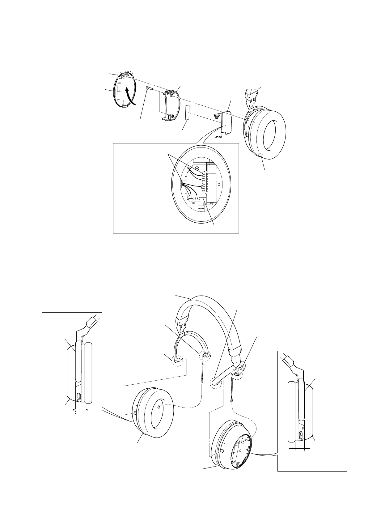
2-3. MR BOARD
4
battery lid assy
3
claw
2
5
two screws
7
8
Remove twelve solders.
6
PC board cover (R)
saranet cushion
9
MR board
MDR-NC60
Press the open button
1
to open the battery lid assy.
2-4. HEAD BAND ASSY
7
hanger
6
9
head band assy
Open and remove without
giving an excessive force.
Open and remove without
giving an excessive force.
MR board
2
Open and remove without
giving an excessive force.
3
Open and remove without
giving an excessive force.
hanger
housing
block (R)
5
Make the hanger
and the housing block
(R) parallel.
8
housing block (R)
4
housing block (L)
housing
block (L)
1
Make the hanger and the
housing block (L) parallel.
5
MDR-NC60
e
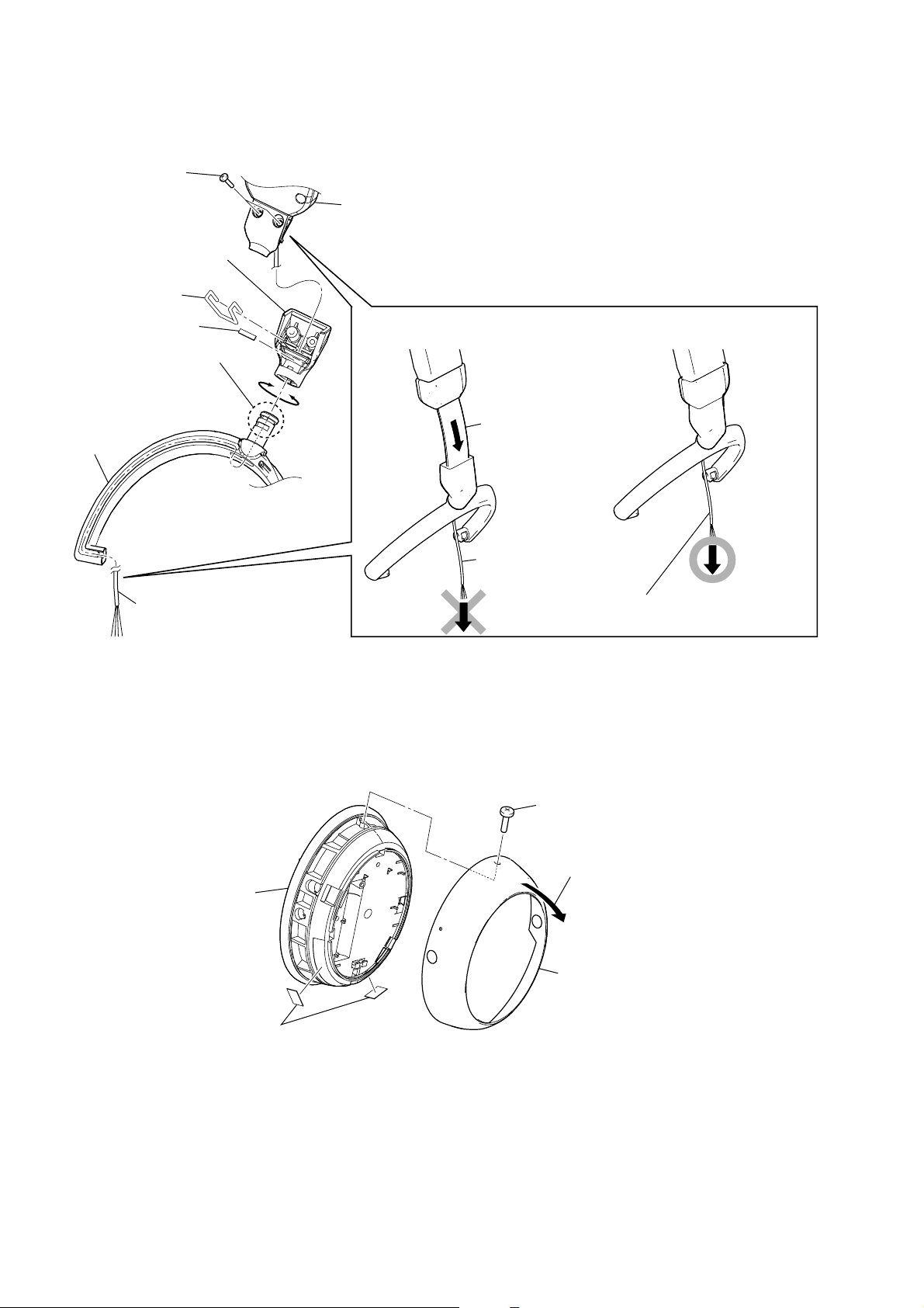
2-5. HANGER (L/R)
Note: Use the same method as that on the L side when removing the hanger (R).
2
two screws
head band section
6
hanger stopper (L)
3
swivel spring
4
swivel plate
5
Rotate this part of hanger
so that it comes to the
position shown,
and then remove from the
hanger stopper.
7
hanger (L)
1
Remove the cord from the
groove in the hanger.
2-6. HOUSING CAP (L/R)
POINT TO NOTES
NG OK
slider
Never draw out the cord
when the slider is extended.
The cord may be drawn out
when the slider is not extended.
Note: Use the same method as that on the L side when removing the housing cap (R).
front plate (L) assy
4
two cap housing adhesive sheets
Note: Cap housing adhesive sheets cannot re-used.
Please replace to brand-new part ones
cap housing adhesive sheets is removed.
1
screw (B1.4)
2
Pull up the housing cap (L) from the sid
where the screw was removed.
3
housing cap (L)
6

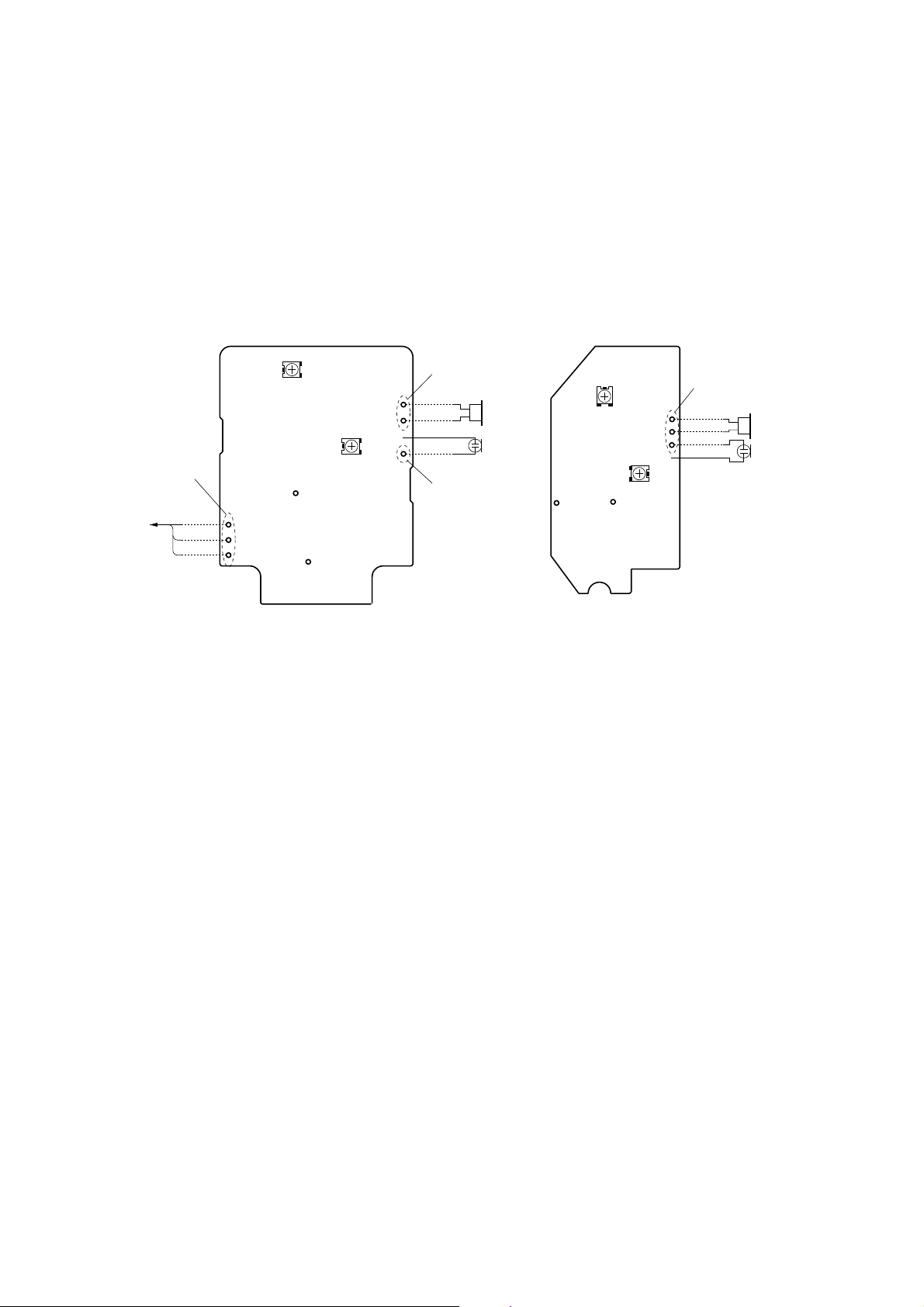
2-7. POSITION OF LEAD WIRES
)
MIC NC wire
(MIC2)
MIC monitor wire
(MIC1)
NATURAL
RED
RED
GREEN
WHITE
NATURAL
NATURAL
RED
driver wire (SP1)
RED
NATURAL
NATURAL
RED
MIC NC wire
(MIC102)
MDR-NC60
– MR board –– ML board –
saranet cushion
driver wire (SP101
RED
NATURAL
RED
NATURAL
RED
GREEN
WHITE
NATURAL
GREEN
RED
NATURAL
main jack wire
cord relay wire
main moniter wire
power switch wire
RED
GREEN
ML board
power LED wire
GREEN
NATURAL
NATURAL
7
MDR-NC60
2
SECTION 3
ELECTRICAL ADJUSTMENT
NOISE CANCELING VOLUME ADJUSTMENT
1 AMP Gain Adjustment
Preparation:
– L-CH –
1. Remove wires of the TP903, TP904, TP905. (for HP board (audio in jack))
2. Remove wires of the TP915, TP916. (for SP1)
3. Remove wire of the TP913, (for MIC2)
– R-CH –
4. Remove wires of the TP932, TP933. (for SP101)
5. Remove wire of the TP930. (for MIC102)
– ML BOARD (SIDE A) –
RV2
from HP board
(audio in jack)
Remove
Green
Red
Natural
TP2
TP903
TP904
TP905
TP3
Setting:
– L-CH –
1. Connect resistors to the TP903, TP904, TP905.
2. Connect a resistor to the TP915, TP916.
3. Connect a lead wire to the TP2.
– R-CH –
4. Connect a resistor to the TP932, TP933.
5. Connect a lead wire to the TP102.
RV1
TP915
TP916
TP913
Remove
Red
Natural
Natural
Red
Remove
Figure 1
SP1
MIC2
– MR BOARD (SIDE A) –
RV102
TP932
TP933
TP930
RV101
TP102
TP103
Remove
Red
Natural
Red
Natural
SP101
MIC10
8
 Loading...