

Sony MDRNC-50 Service manual
MDR-NC50
SERVICE MANUAL
Ver. 1.2 2005.02
SPECIFICATIONS
General
Type Dynamic, closed
Driver units 40 mm, dome type
Power handling capacity
Impedance 40 Ω at 1 kHz (when the power is on)
Sensitivity 102 dB/mW (when the power is on)
Frequency response
Frequency range of active noise attenuation
Power source DC 1.5 V, 1 × R03 (size AAA) battery
Mass
Battery life
Battery
Sony alkaline LR03/AM-4 (N)
(size AAA) battery
Sony manganese R03/ UM-4
(NU) (size AAA) battery
*11 kHz, 1 mW + 1 mW input
2
*
Time stated above may vary, depending on the temperature or conditions of use.
When to replace the battery
Replace the battery with a new one when the POWER indicator dims.
The noise canceling feature may not work correctly if battery power is low.
Supplied accessories
Connecting cord (0.5 m, gold-plated stereo mini plug (1) (Tourist only),
1.5 m, gold plated L type stereo mini plug (1)), R03 (size AAA) dry
battery (1) (Tourist only), Carrying case (1), Plug adaptor for in-flight
use* (single/dual) (1), Gold-plated unimatch plug adaptor (stereo phone
plug y stereo mini jack) (1), Operating Instructions (1)
* May not be compatible with some in-flight music services.
100 mW
100 Ω at 1 kHz (when the power is off)
100 dB/mW (when the power is off)
14 − 22,000 Hz
40 − 1,500 Hz, more than 14 dB at 300 Hz
Approx. 290 g (11 oz) including battery
Approx. hours*
30 hours*
15 hours*
1
2
2
US Model
Canadian Model
AEP Model
UK Model
E Model
Tourist Model
UNLEADED SOLDER
Boards requiring use of unleaded solder are printed with the leadfree mark (LF) indicating the solder contains no lead.
(Caution: Some printed circuit boards may not come printed with
the lead free mark due to their particular size)
: LEAD FREE MARK
Unleaded solder has the following characteristics.
• Unleaded solder melts at a temperature about 40 ˚C higher
than ordinary solder.
Ordinary soldering irons can be used but the iron tip has to be
applied to the solder joint for a slightly longer time.
Soldering irons using a temperature regulator should be set to
about 350 ˚C.
Caution: The printed pattern (copper foil) may peel away if
the heated tip is applied for too long, so be careful!
• Strong viscosity
Unleaded solder is more viscou-s (sticky, less prone to flow)
than ordinary solder so use caution not to let solder bridges
occur such as on IC pins, etc.
• Usable with ordinary solder
It is best to use only unleaded solder but unleaded solder may
also be added to ordinary solder.
Note on chip component replacement
• Never reuse a disconnected chip componet
• Notice that the minus side of a teamtalum capacitor may be damaged by
heat
Design and specifications are subject to change without notice.
9-879-314-03
2005B05-1
© 2005.02
Sony Corporation
Personal Audio Group
Published by Sony Engineering Corporation
NOISE CANCELING
HEADPHONES

MDR-NC50
TABLE OF CONTENTS
1. GENERAL ................................................................... 3
2. DISASSEMBLY
2-1. Disassembly Flow ........................................................... 4
2-2. ML Board ........................................................................ 4
2-3. MR Board ........................................................................ 5
2-4. Ornamental Cap (L)/(R) .................................................. 5
2-5. Position of lead Wires...................................................... 6
2-6. L/R Transition Cord Location ......................................... 6
2-7. Position Of Lead Wires
At Front Plate (L)/(R) Sub Assy...................................... 7
3. ELECTRICAL ADJUSTMENT ............................. 8
4. DIAGRAMS................................................................. 9
4-1. Block Diagram ................................................................ 11
4-2. Printed Wiring Board – L-CH Board – ........................... 12
4-3. Printed Wiring Boards – R-CH Board –.......................... 13
4-4. Schematic Diagram ......................................................... 14
5. EXPLODED VIEWS
5-1. Overall Section ................................................................ 15
5-2. Housing (L) Section ........................................................ 16
5-3. Housing (R) Section ........................................................ 17
6. ELECTRICAL PARTS LIST................................ 18
2
This section is extracted from
instruction manual.
SECTION 1
GENERAL
MDR-NC50
Ver. 1.1
Features
• Noise cancelling headphones reduce ambient
noise, and provide a quieter environment to
enhance audio entertainment.
Ambient sound is synthesized with an antisound signal produced by the noise cancelling
circuit, and reduced. (Over 14 dB is reduced at
300 Hz.)
• Slim, folding design for easy portability.
• Neodymium magnets for powerful sound.
• Passive operation when noise-canceling circuit
is not activated.
• Built-in monitor function to hear surrounding
sound without taking off the headphones.
• Supplied plug adaptor for easy connectivity to
stereo or dual jack of in-flight music services.
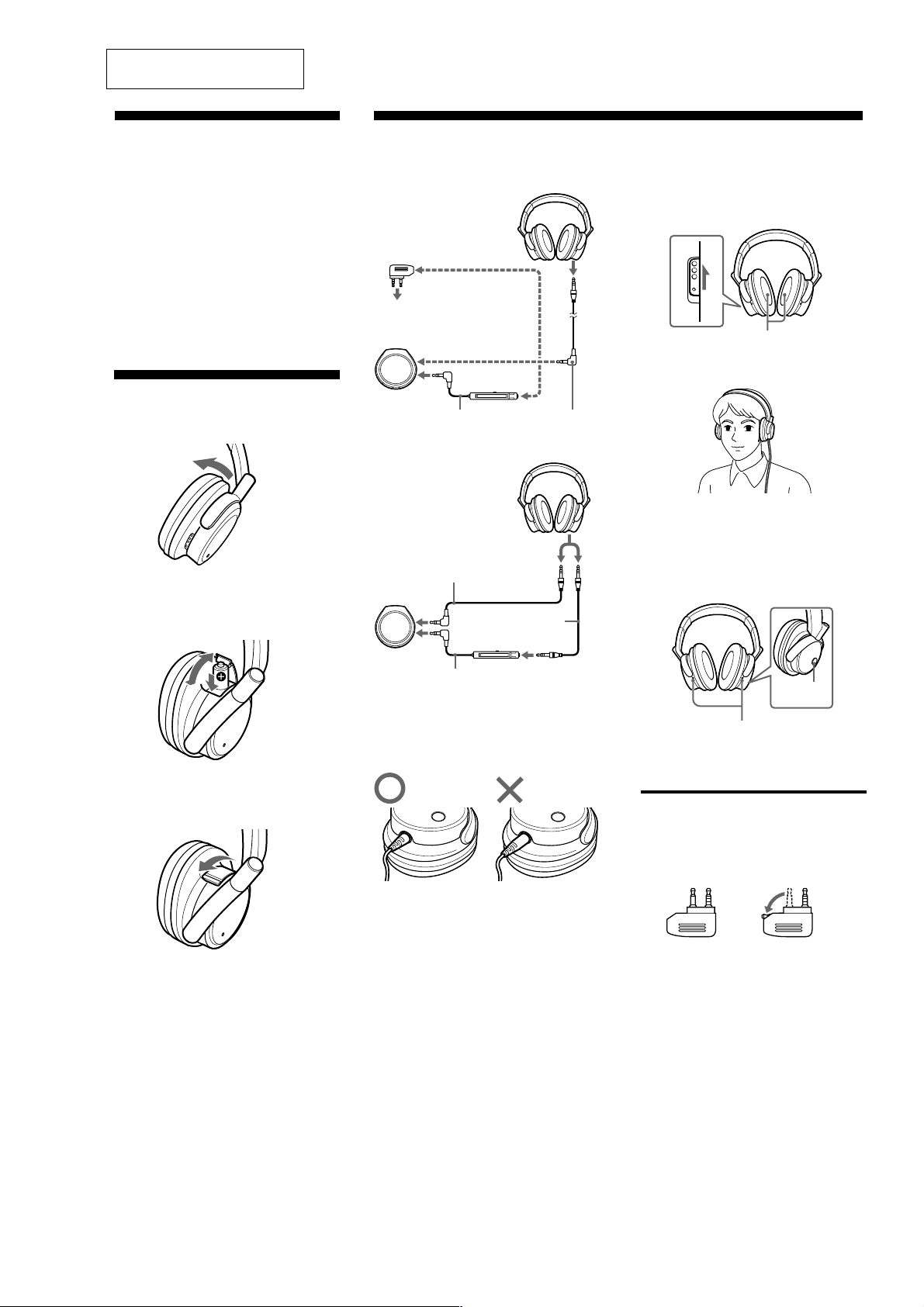
Installing a battery
1
Open the right housing, as illustrated.
2
Open the lid of the battery box of the
headphone to insert one size AAA battery.
Match the e on
the battery to the
e in the battery
case.
3
Close the lid.
Listening to music
1
Connect the headphones to the AV
equipment.
(Except Tourist)
When connecting to dual
or stereo mini jacks of
in-flight music services.
Plug adaptor (supplied)
To headphone jack on
airplane seats
When connecting to the stereo
mini jack of the remote control’s
jack supplied with a WALKMAN*,
etc.
(Tourist only)
When connecting to the
stereo mini plug of a
WALKMAN*, etc
WALKMAN*, etc
When connecting to the stereo mini jack of the remote
control’s jack supplied with a WALKMAN*, etc
* “WALKMAN” is a registered trademark of Sony
Corporation to represent Headphone Stereo products.
Note
• Insert the plug in the jack until you hear a click.
Headphones
When connecting to the
stereo mini jack of a
WALKMAN*, etc.
Remote control
Headphones
Connecting cord
1.5 m (supplied)
Connecting cord
0.5 m (supplied)
Remote control
Connecting cord
1.5 m (supplied)
2
Turn on the power on the right side of the
headphones.
The POWER indicator lights in red. When the
power is turned on, ambient noise is reduced,
and you can listen to music more clearly at a
lower volume.
LR
3
ON OFF
LR
Noise canceling microphone
Put on the headphones so that the ear pads
cover your ears.
RL
LR
4
Turn on the power of the AV equipment.
Hearing environmental sound for safety.
Playback is muted while the MONITOR switch is
pushed so you can hear the surrounding
environment.
LR
MONITOR
switch
monitor microphone
Note
The environmental sound might not be heard if the
microphone is covered with your fingers.
Notes on using on the
airplane
• The supplied plug adaptor can be connected to dual
and stereo mini jacks.
for dual jacks for stereo mini jacks
• To disconnect the cord, pull it out by the plug, not the
cord, as the inner conductors may break.
• Do not use the headphones when use of electronic
equipment is prohibited or when use of personal
headphones for in-flight music services is prohibited.
If you have any questions or problems concerning the
system that are not covered in this manual, please consult
the nearest Sony dealer.
3
MDR-NC50
r
SECTION 2
DISASSEMBLY
Note: Follow the disassembly procedure in the numerical order given.
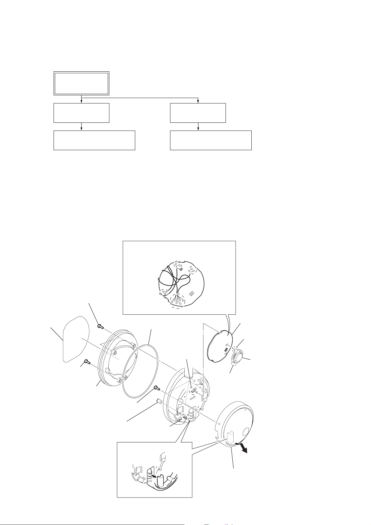
2-1. DISASSEMBLY FLOW
SET
2-2. ML BOARD
(Page 4)
2-4. ORNAMENTAL CAP (L)/(R)
(Page 5)
Note: Follow the disassembly procedure in the numerical order given.
2-2. ML BOARD
qd
Remove thirteen solders.
2-3. MR BOARD
(Page 5)
2-4. ORNAMENTAL CAP (L)/(R)
(Page 5)
1
screen
2
3
two screws
(B2.6)
4
two screws
(B2.6)
front plate (L)
assy
7
sheet (housing)
6
three screws
(B2.6)
5
packing housing
8
claw
qf
claw
qg
ML board
0
claw
qs
qa
claw
9
Remove the ring (L) block
in the direction of arrow.
button monito
4
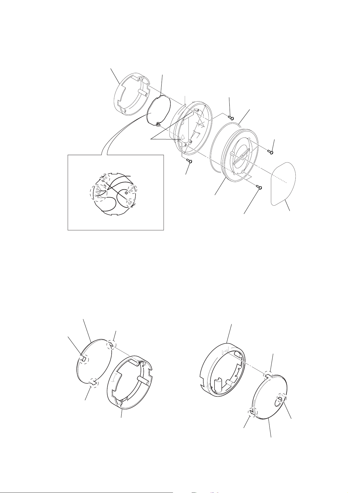
2-3. MR BOARD
)
9
Remove thirteen solders.
8
ring (R) block
q;
two claws
qa
MR board
7
screw
(B2.6)
6
two screws
(B2.6)
5
packing housing
3
two screws
(B2.6)
MDR-NC50
4
front plate (R)
assy
2-4. ORNAMENTAL CAP (L)/(R)
Take care not to break the claw when mounting or demounting the ornamental cap (L)/(R).
3
ornamental cap (R)
1
claw
1
claw
2
2
two screws
(B2.6)
ring (L)
1
claw
1
screen
1
claw
2
ring (R)
1
claw
1
3
ornamental cap (L
claw
5
MDR-NC50
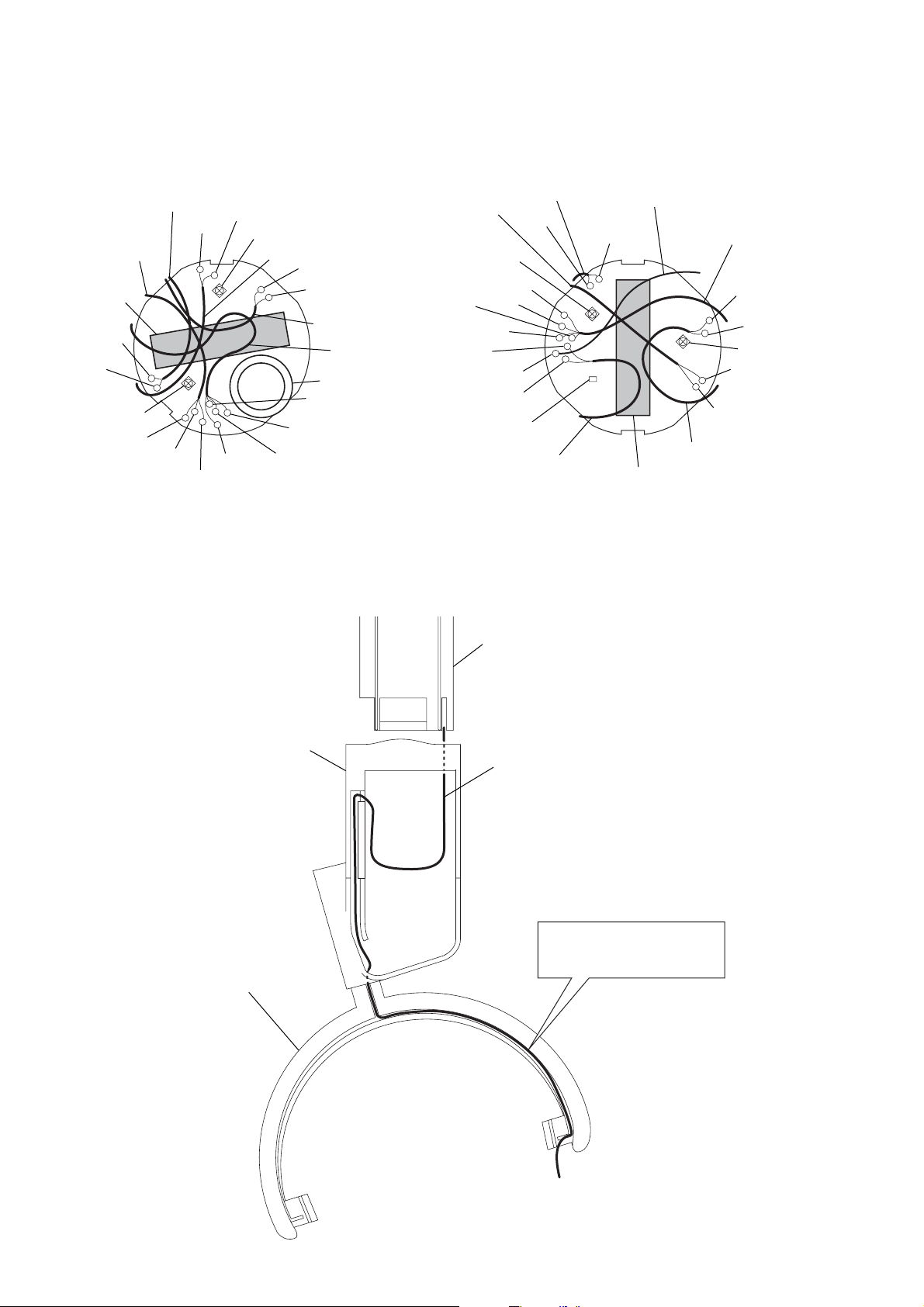
2-5. POSITION OF LEAD WIRES
– MR board –– ML board –
MIC2
jack
(small type)
sheet
(housing)
NATURAL
RED
RV2
NATURAL
GREEN
RED
RED
NATURAL
RV1
GREEN
MIC1
RED
NATURAL
SP1
L/R transition
cord
button monitor
RED
BLACK
NATURAL
2-6. L/R TRANSITION CORD LOCATION
SP101
BLACK
NATURAL
RV101
GREEN
RED
RED
BLACK
RED
LED
SW transition
cord
head band assy
MIC102
RED
BATT
NATURAL
sheet (housing)
L/R transition
cord
RED
NATURAL
RV102
RED
NATURAL
MIC101
guide slider (L)/(R)
hanger (L)/(R)
L/R transition cord
L/R transition cord is inserted
in the slot inside a hanger.
6
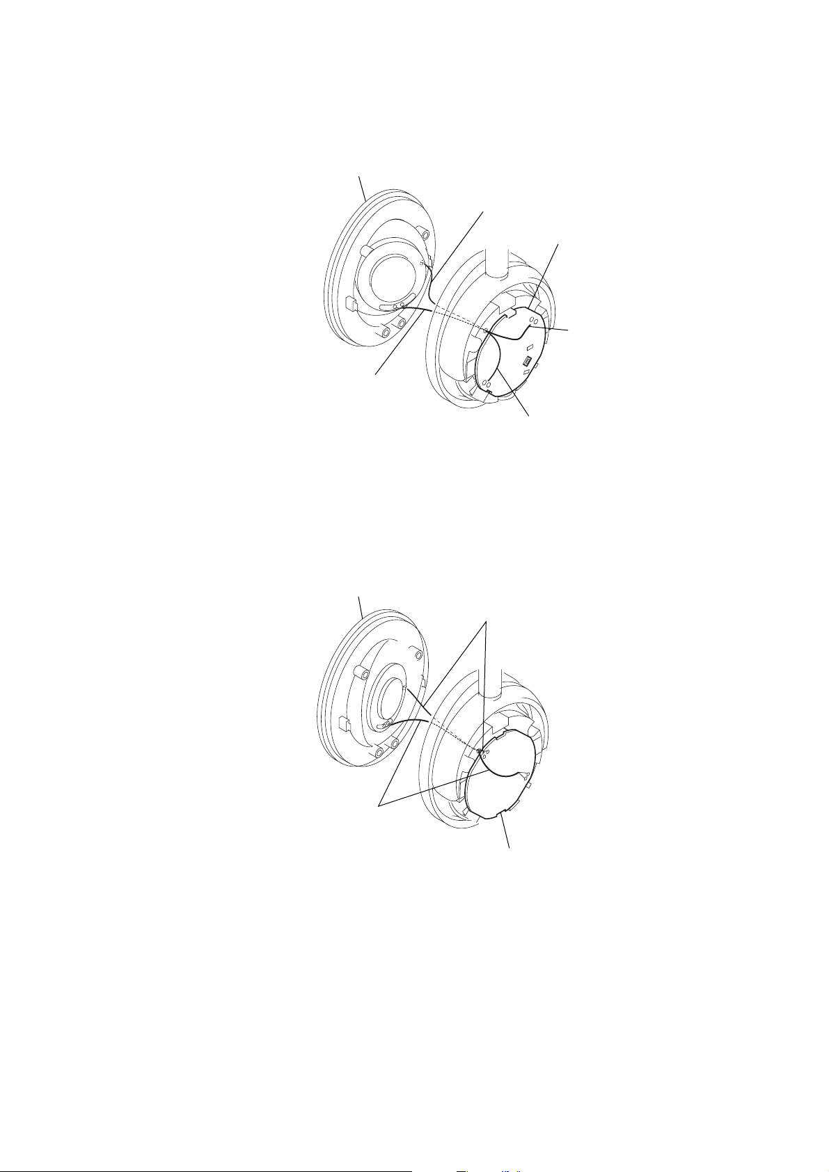
2-7. POSITION OF LEAD WIRES AT FRONT PLATE (L)/(R) SUB ASSY
d
d
front plate sub assy (L)
MIC2
ML boar
SP1
MIC2
MDR-NC50
SP1
front panel sub assy (R)
SP101
MIC102
MR boar
7
 Loading...