

Sony MCC-500MD Instructions For Use Manual

HD Video Camera
4-529-125-12 (1)
Instructions for Use
Before operating the unit, please read this manual thoroughly
and retain it for future reference.
MCC-500MD
© 2014 Sony Corporation
WARNING
Symbols on the products
To reduce the risk of fire or
electric shock, do not expose this
apparatus to rain or moisture.
To avoid electrical shock, do not
open the cabinet. Refer servicing
to qualified personnel only.
No modification of this equipment is allowed.
WARNING
THIS APPARATUS MUST BE EARTHED.
WARNING
This unit has no power switch.
To disconnect the main power, unplug the
power plug.
When installing the unit, incorporate a readily
accessible disconnect device in the fixed
wiring, or connect the power plug to an easily
accessible socket-outlet near the unit.
Do not position the ME equipment where it is
difficult to unplug the power plug.
If a fault should occur during operation of the
unit, operate the disconnect device to switch
the power supply off, or unplug the power
plug.
Do not install the appliance in a confined
space, such as book case or built-in cabinet.
CAUTION
The apparatus shall not be exposed to
dripping or splashing. No objects filled with
liquids, such as vases, shall be placed on the
apparatus.
General warning sign
Follow the warnings in the
Instructions for use for parts of the
unit on which this mark appears.
NOTE Background color: Yellow
Triangular band: Black
Symbol: Black
Consult the Instructions for use
Follow the directions in the
Instructions for use for parts of the
unit on which this mark appears.
This symbol indicates the
manufacturer, and appears next to
the manufacturer’s name and
address.
This symbol indicates the
European Community
representative, and appears next
to the European Community
representative’s name and
address.
This symbol indicates the
equipotential terminal which
brings the various parts of a
system to the same potential.
For the customers in the U.S.A.
This equipment has been tested and found to
comply with the limits for a Class A digital
device, pursuant to part 15 of the FCC Rules.
These limits are designed to provide
reasonable protection against harmful
interference when the equipment is operated
in a commercial environment. This
equipment generates, uses, and can radiate
radio frequency energy and, if not installed
and used in accordance with the instruction
manual, may cause harmful interference to
radio communications. Operation of this
equipment in a residential area is likely to
cause harmful interference in which case the
user will be required to correct the
interference at his own expense.
You are cautioned that any changes or
modifications not expressly approved in this
manual could void your authority to operate
this equipment.
2

All interface cables used to connect
peripherals must be shielded in order to
comply with the limits for a digital device
pursuant to Subpart B of part 15 of FCC
Rules.
For the customers in the U.S.A.
This device complies with part 15 of the FCC
Rules.
Operation is subject to the following two
conditions:
(1) This device may not cause harmful
interference, and
(2) this device must accept any interference
received, including interference that may
cause undesired operation.
For the customers in Canada
CAN ICES-3 (A)/NMB-3(A)
For the customers in Canada
This unit has been certified according to
Standard CAN/CSA-C22.2 No.60601-1.
WARNING on power connection
Use a proper power cord for your local power
supply.
1. Use the approved Power Cord (3-core
mains lead) / Appliance Connector / Plug
with earthing-contacts that conforms to
the safety regulations of each country if
applicable.
2. Use the Power Cord (3-core mains
lead) / Appliance Connector / Plug
conforming to the proper ratings
(Voltage, Ampere). If you have
questions on the use of the above Power
Cord / Appliance Connector / Plug,
please consult a qualified service
personnel.
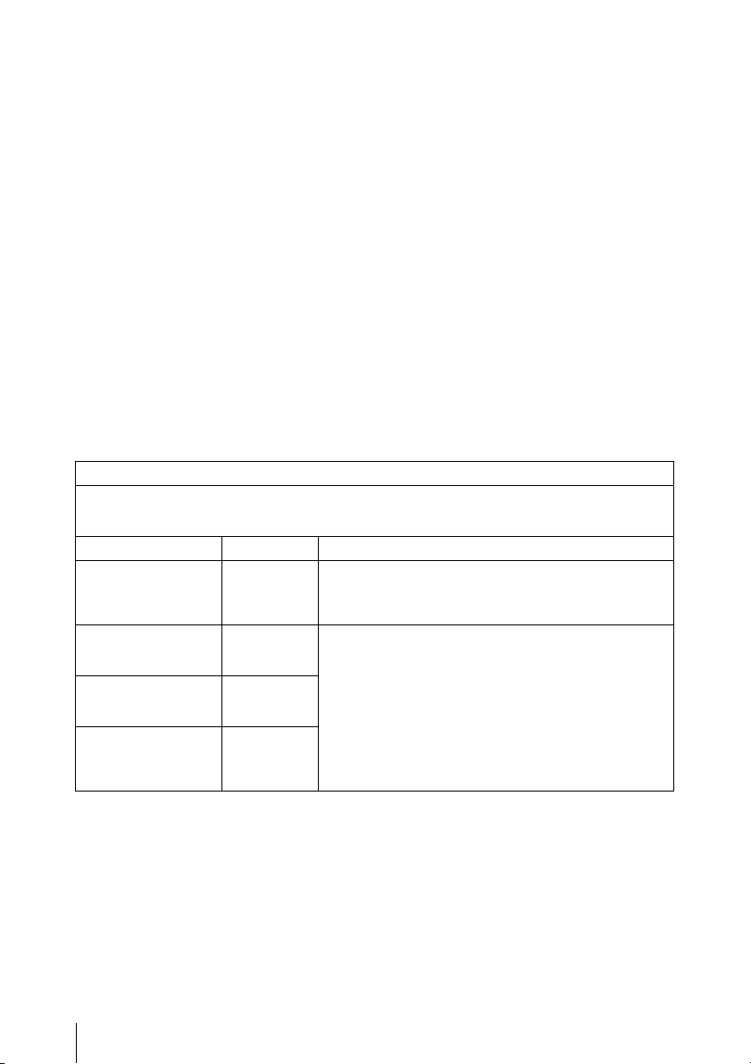
Warning on power connection for medical use
Please use the following power supply cord.
With connectors (plug or female) and cord
types other than those indicated in this table,
use the power supply cord that is approved
for use in your area.
United States and
Canada
Plug Type HOSPITAL GRADE*
Cord Type Min.Type SJT
Minimum Rating for
Plug and Appliance
Couplers
Safety Approval UL Listed and CSA
*Note: Grounding reliability can only be
achieved when the equipment is connected
to an equivalent receptacle marked ‘Hospital
Only’ or ‘Hospital Grade’.
Min.18 AWG
10A/125V
For the customers in the U.S.A and Canada
When you use this product connected to
240 V single phase, be sure to connect this
product to a center tapped circuit.
Important safeguards/notices for use in the
medical environments
1. All the equipments connected to this unit
shall be certified according to Standard
IEC60601-1, IEC60950-1, IEC60065 or
other IEC/ISO Standards applicable to
the equipments.
2. Furthermore all configurations shall
comply with the system standard
IEC60601-1-1. Everybody who connects
additional equipment to the signal input
part or signal output part configures a
medical system, and is therefore,
responsible that the system complies
with the requirements of the system
standard IEC60601-1-1.
If in doubt, consult the qualified service
personnel.
3. The leakage current could increase
when connected to other equipment.
4. For this particular equipment, all
accessory equipment connected as
noted above, must be connected to
mains via an additional isolation
transformer conforming with the
construction requirements of IEC606011 and providing at least Basic Insulation.
5. This equipment generates, uses, and
can radiate radio frequency energy. If it
is not installed and used in accordance
with the instruction manual, it may cause
interference to other equipment. If this
3
unit causes interference (which can be
determined by unplugging the power
cord from the unit), try these measures:
Relocate the unit with respect to the
susceptible equipment. Plug this unit and
the susceptible equipment into different
branch circuit.
Consult your dealer. (According to standard
IEC60601-1-2 and CISPR11, Class B,
Group 1)
Important EMC notices for use in the medical environments
• The MCC-500MD needs special precautions regarding EMC and needs to be installed and put
into service according to the EMC information provided in this instructions for use.
• The portable and mobile RF communications equipment such as cellular phones can affect the
MCC-500MD.
Warning
The use of accessories and cables other than those specified, with the exception of replacement
parts sold by Sony Corporation, may result in increased emissions or decreased immunity of the
MCC-500MD.
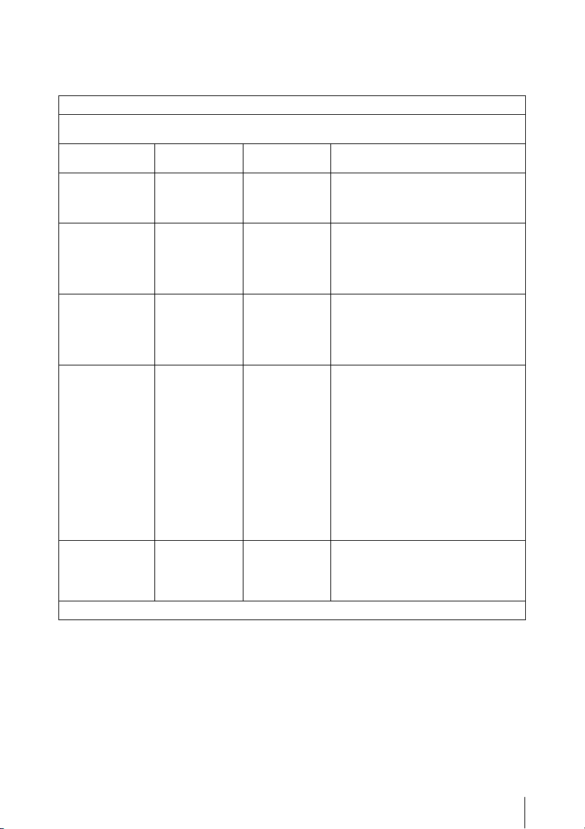
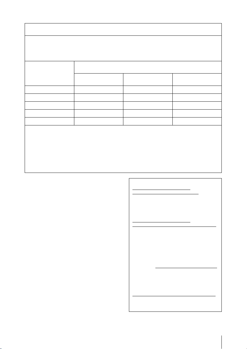
Guidance and manufacturer’s declaration-electromagnetic emissions
The MCC-500MD is intended for use in the electromagnetic environment specified below.
The customer or the user of the MCC-500MD should assure that it is used in such an
environment.
Emission test Compliance Electromagnetic environment-guidance
RF emissions
CISPR 11
RF emissions
CISPR 11
Harmonic emissions
IEC 61000-3-2
Voltage fluctuations/
flicker emissions
IEC 61000-3-3
Group 1 The MCC-500MD uses RF energy only for its internal
Class B The MCC-500MD is suitable for use in all
Class A
Complies
function. Therefore, its RF emissions are very low and
are not likely to cause any interference in nearby
electronic equipment.
establishments, including domestic establishments and
those directly connected to the public low-voltage power
supply network that supplies buildings used for domestic
purposes.
4
Warning
If the MCC-500MD should be used adjacent to or stacked with other equipment, it should be
observed to verify normal operation in the configuration in which it will be used.
Guidance and manufacturer’s declaration - electromagnetic immunity
The MCC-500MD is intended for use in the electromagnetic environment specified below. The
customer or the user of the MCC-500MD should assure that it is used in such as environment.
Immunity test IEC 60601 test
Electrostatic
discharge (ESD)
IEC 61000-4-2
Electrical fast
transient/burst
IEC 61000-4-4
Surge
IEC 61000-4-5
Voltage dips,
short
interruptions and
voltage
variations on
power supply
input lines
IEC 61000-4-11
Power frequency
(50/60Hz)
magnetic field
level
±6 kV contact
±8 kV air
±2 kV for
power supply
lines
±1 kV for input/
output lines
±1 kV
differential
mode
±2 kV common
mode
< 5% U
T
(> 95% dip in
U
) for 0.5
T
cycle
40% U
T
(60% dip in U
for 5 cycles
70% U
T
(30% dip in U
for 25 cycles
< 5% U
T
(> 95% dip in
U
) for 5 sec
T
3 A/m 3 A/m Power frequency magnetic fields
IEC 61000-4-8
NOTE: U
is the a.c. mains voltage prior to application of the test level.
T
±6 kV contact
±8 kV air
±2 kV for
power supply
lines
±1 kV for input/
output lines
±1 kV
differential
mode
±2 kV common
mode
< 5% U
(> 95% dip in
U
cycle
40% U
(60% dip in U
)
T
for 5 cycles
70% U
(30% dip in U
)
T
for 25 cycles
< 5% U
(> 95% dip in
U
Compliance
level
T
) for 0.5
T
T
T
T
) for 5 sec
T
Electromagnetic environment-
Floors should be wood, concrete or
ceramic tile. If floors are covered with
synthetic material, the relative humidity
should be at least 30 %.
Mains power quality should be that of
a typical commercial or hospital
environment.
Mains power quality should be that of
a typical commercial or hospital
environment.
Mains power quality should be that of
a typical commercial or hospital
environment. If the user of the
MCC-500MD requires continued
operation during power mains
interruptions, it is recommended that
the MCC-500MD be powered from an
)
T
uninterruptible power supply or a
battery.
)
T
should be at least characteristic of a
typical location in a typical commercial
or hospital environment.
guidance
5
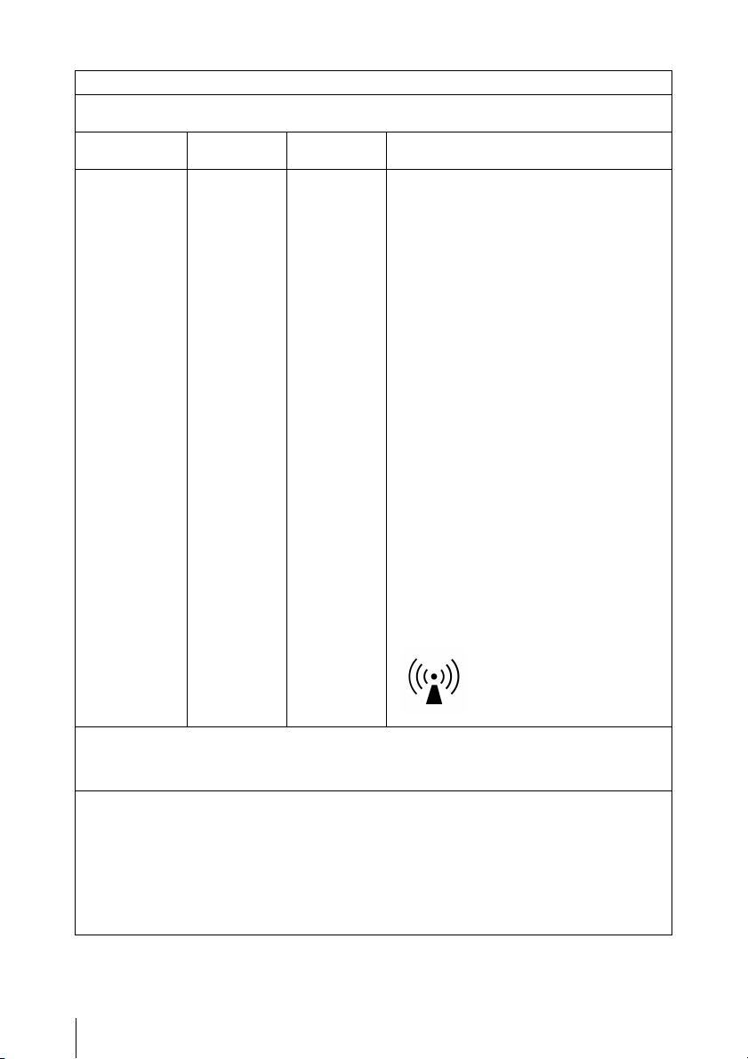
Guidance and manufacturer’s declaration - electromagnetic immunity
The MCC-500MD is intended for use in the electromagnetic environment specified below. The
customer or the user of the MCC-500MD should assure that it is used in such as environment.
Immunity test IEC 60601
test level
Compliance
level
Electromagnetic environment - guidance
Portable and mobile RF communications
equipment should be used no closer to any
part of the MCC-500MD, including cables,
than the recommended separation distance
calculated from the equation appliance to the
frequency of the transmitter.
Recommended separation distance
Conducted RF
IEC 61000-4-6
3 Vrms
150 kHz to
80 MHz
3 Vrms
d = 1.2√P
Radiated RF
IEC 61000-4-3
3 V/m
80 MHz to
2.5 GHz
3 Vrms
d = 1.2√P 80 MHz to 800 MHz
d = 2.3√P 800 MHz to 2.5 GHz
Where P is the maximum output power rating
of the transmitter in watts (W) according to
the transmitter manufacturer and d is the
recommended separation distance in meters
(m).
Field strengths from fixed RF transmitters, as
determined by an electromagnetic site
a
survey,
should be less than the compliance
level in each frequency range.
Interference may occur in the vicinity of
equipment marked with following symbol:
b
NOTE 1: At 80 MHz and 800 MHz, the higher frequency range applies.
NOTE 2: These guidelines may not apply in all situations. Electromagnetic propagation is affected
a Field strengths from fixed transmitters, such as base stations for radio (cellular/cordless)
by absorption and reflection from structures, objects and people.
telephones and land mobile radios, amateur radio, AM and FM radio broadcast and TV
broadcast cannot be predicted theoretically with accuracy. To assess the electromagnetic
environment due to fixed RF transmitters, an electromagnetic site survey should be considered.
If the measured field strength in the location in which the MCC-500MD is used exceeds the
applicable RF compliance level above, the MCC-500MD should be observed to verify normal
operation. If abnormal performance is observed, additional measures may be necessary, such
as reorienting or relocating the MCC-500MD.
b Over the frequency range 150 kHz to 80 MHz, field strengths should be less than 3 V/m.
6
Recommended separation distances between portable and mobile RF communications
The MCC-500MD is intended for use in an electromagnetic environment in which radiated RF
disturbances are controlled. The customer or the user of the MCC-500MD can help prevent
electromagnetic interference by maintaining a minimum distance between portable and mobile RF
communications equipment (transmitters) and the MCC-500MD as recommended below,
according to the maximum output power of the communications equipment.
Rated maximum
output power of
transmitter
W
0.01 0.12 0.12 0.23
0.1 0.380.380.73
1 1.2 1.2 2.3
10 3.8 3.8 7.3
100 12 12 23
For transmitters rated a maximum output power not listed above, the recommended separation
distance d in meters (m) can be estimated using the equation applicable to the frequency of the
transmitter, where P is the maximum output power rating of the transmitter in watts (W) according
to the transmitter manufacturer.
NOTE 1: At 80 MHz and 800 MHz, the separation distance for the higher frequency range
NOTE 2: These guidelines may not apply in all situations. Electromagnetic propagation is
applies.
affected by absorption and reflection from structures, objects and people.
equipment and the MCC-500MD
Separation distance according to frequency of transmitter
150 kHz to 80 MHz
d = 1.2√P
m
80 MHz to 800 MHz
d = 1.2√P
800 MHz to 2.5 GHz
d = 2.3√P
Caution
When you dispose of the unit or accessories,
you must obey the laws in the relative area or
country and the regulations in the relative
hospital.
For the customers in Europe
This product has been manufactured by or
on behalf of Sony Corporation, 1-7-1 Konan
Minato-ku Tokyo, 108-0075 Japan.
Inquiries related to product compliance
based on European Union legislation shall be
addressed to the authorized representative,
Sony Deutschland GmbH, Hedelfinger
Strasse 61, 70327 Stuttgart, Germany.
For any service or guarantee matters, please
refer to the addresses provided in the
separate service or guarantee documents.
For the customers in the U.S.A.
SONY LIMITED WARRANTY - Please visit
http://www.sony.com/psa/warranty
important information and complete terms
and conditions of Sony’s limited warranty
applicable to this product.
for
For the customers in Canada
SONY LIMITED WARRANTY - Please visit
http://www.sonybiz.ca/solutions/Support.do
for important information and complete
terms and conditions of Sony’s limited
warranty applicable to this product.
For the customers in Europe
Sony Professional Solutions Europe Standard Warranty and Exceptions on
Standard Warranty.
Please visit http://www.pro.sony.eu/warranty
for important information and complete
terms and conditions.
For the customers in Korea
SONY LIMITED WARRANTY - Please visit
http://bpeng.sony.co.kr/handler/BPAS-Start
for important information and complete
terms and conditions of Sony’s limited
warranty applicable to this product.
7

Precautions for Use
Safety precautions for using this unit
• Viewing images may result in eye strain,
fatigue, nausea, or other symptoms of
discomfort. It is best to take frequent breaks
when viewing content. Because the length and
frequency of breaks will differ from person to
person, be sure to trust your instincts when
deciding to take breaks from viewing. When
feelings of discomfort occur, stop viewing the
images until the symptoms subside, and consult
with a specialist physician if necessary.
• Avoid using this unit while walking or
exercising, or in areas that shake violently, as
doing so can increase the chances of feelings of
discomfort.
• When connecting the unit to medical
equipment, refer to “Precautions when
connecting this unit to medical equipment”.
Precautions when connecting this unit to
medical equipment
• Before using this unit for medical purposes, be
sure to confirm that use of this unit will not
cause symptoms that may interfere with
medical practice, such as eye strain, fatigue, and
nausea, etc.
• Refrain from using this unit if symptoms occur
that interfere with medical practice, or if such
symptoms are likely to occur.
• Depending on the conditions of the video input
to the unit (e.g., the steadiness, movement
speed, and focus position of the video, the
distance from subject, the area of the image the
user is viewing) and the general health of the
user, the user may experience visual fatigue,
tiredness, and other discomfort.
Precautions when using a harmonic
scalpel
Strong electromagnetic waves or voltage from
equipment such as a harmonic scalpel may cause
images may appear rough or distorted, etc., or
disrupt proper operation of the unit when used at
the same time. However, this does not indicate a
malfunction.
When using this unit with equipment that emits
strong electromagnetic waves or voltage, check
the effects of such equipment beforehand and
place the unit in a location where those effects
will be limited, or discontinue use of the unit with
such equipment.
Usage and storage locations
Store the unit in a level, well-ventilated place.
Avoid using or storing the unit in the following
places.
• Extremely cold or hot locations (Operating
temperatures: 0 ºC to 40 ºC (32 ºF to 104 ºF))
• Locations in direct sunlight for long periods, or
close to heating appliances (The inside of a
vehicle can reach up to 50 ºC (122 ºF) in the
summer when the windows are closed.)
• Humid or dusty places
• Locations where the unit may be exposed to rain
• Locations subject to strong vibrations
• Locations close to strong magnetic fields
• Near TVs that emit strong electromagnetic
waves, or near locations where radio waves are
emitted
• Locations with a strong risk of fire or explosion
Precautions concerning laser beams
Laser beams may damage the CMOS image
sensor. When shooting scenes that include laser
beams, be careful not to allow laser beams to hit
the surface of the CMOS image sensor (do not let
laser beams enter the lens).
Do not subject the unit to strong impacts
Dropping the camera head or exposing it to
excessive shocks may damage it.
Do not block the camera vents
To prevent the interior of the unit from
overheating, maintain a clearance of at least
10 cm (4 in.) around the unit.
Do not subject the unit to sudden
changes in temperature
Sudden changes in temperature may affect the
camera picture output.
Precautions for Use
8

Do not leave the unit with the camera
facing the sun
Sunlight can enter the camera, be focused inside
the unit and cause a fire.
Cleaning
If the casing, panel, or camera cable becomes
dirty, wipe them gently with a soft, dry cloth.
For stubborn dirt, use a cloth wet with mild liquid
detergent to wipe the unit, and then wipe it with a
dry cloth. Using alcohol, thinner, benzine,
insecticides, or other volatile substances may
damage the surface of the unit or remove the
finish.
Use isopropyl alcohol with a concentration of
50% to 70% (v/v) or ethanol with a concentration
of 76.9% to 81.4% (v/v) to clean the surface of the
unit.
Transporting the unit
When transporting the unit, use the original
carton and packing to wrap it and ensure it is not
subject to violent impacts.
After use
Press the 1 (on/standby) button to turn the
standby mode.
When not using the unit for a long period
of time
Disconnect the power cord.
On moisture condensation
If the unit is suddenly taken from a cold to a warm
location, or if ambient temperature suddenly
rises, moisture may form on the outer surface of
the unit and/or inside of the unit. This is known as
condensation. If condensation occurs, turn off the
unit and wait until the condensation clears before
operating the unit. Operating the unit while
condensation is present may damage the unit.
White spots
The CMOS image sensor is fabricated using
extremely high-precision technology, however,
in very rare cases, outside influence, such as
cosmic rays, may cause minute white spots to
appear on the screen. This not a malfunction, but
is related to the principle of the imaging element.
White spots may also be visible in the following
situations.
• When the unit is used in locations subject to
high temperatures
• When the gain is raised
Aliasing
When shooting fine patterns or lines, a jagged or
flickering effect may occur.
Flicker
When shooting under discharge tube lighting,
such as fluorescent lamps, sodium lamps, or
mercury vapor lamps, the screen may flicker,
change color, or horizontal stripes may appear to
roll across the screen.
Focal plane
Due to characteristics of how the CMOS image
sensor reads image signals, subjects that quickly
move across the screen may appear slightly
distorted.
Additionally, light from a flash or quickly
flashing light sources may cause the brightness to
change at the top and bottom of the screen.
Precautions concerning heat generation
by the unit
Be careful during operation of the unit, as the
metal surfaces of the unit may become hot.
Generation of heat during operation of the unit is
not a malfunction.
Phenomena specific to the CMOS image
sensor
The following phenomena are specific to the
CMOS image sensor, and their presence on the
shooting screen do not indicate malfunctions.
Precautions for Use
9

Intended Use
For the customers in the U.S.A.
The Sony MCC-500MD is intended to acquire
HD color video images from surgical
microscopes and other compatible medical
imaging systems.
The acquired video image can be displayed on a
compatible monitor for visualization during a
surgical procedure as a secondary view to the
microscope binoculars.
The MCC-500MD is a high-definition medical
grade camera for use primarily with surgical
microscope procedures including Neurology and
Ophthalmology.
It is suitable for use in hospital operating rooms,
surgical centers, clinics, doctors’ offices and
similar medical environments.
For the customers in countries other than the
U.S.A.
(1) The Sony MCC-500MD is intended to
acquire HD color video images from surgical
microscopes and other compatible medical
imaging systems.
The acquired video image can be displayed
on a compatible monitor for visualization
during a surgical procedure as a secondary
view to the microscope binoculars.
The MCC-500MD is a high-definition
medical grade camera for use primarily with
surgical microscope procedures including
Neurology and Ophthalmology.
It is suitable for use in hospital operating
rooms, surgical centers, clinics, doctors’
offices and similar medical environments.
(2) The Sony MCC-500MD is also intended to
acquire HD color video images from slit
lamps and other compatible medical imaging
systems.
The acquired video image can be displayed
on a compatible monitor for visualization
during an ophthalmological examination as a
secondary view to the slit lamp binoculars.
The MCC-500MD is a high-definition
medical grade camera for use primarily with
slit lamp diagnostics.
It is suitable for use in hospital examination
rooms, clinics, doctors’ offices and similar
medical environments.
10
Intended Use

Table of Contents
Overview
Preparations
Precautions for Use .................................................................... 8
Intended Use............................................................................. 10
Package Configuration ............................................................ 14
Features of This Unit............................................................... 14
Part Names and Functions...................................................... 16
Camera head.................................................................. 16
Camera control unit (CCU) front panel ........................ 16
Camera control unit (CCU) rear panel.......................... 17
Lens Mounting ......................................................................... 19
Mounting the lens.......................................................... 19
Attaching the tripod adapter.......................................... 19
Connection between the Camera Head and CCU................. 20
Connecting the camera cable to the camera head ......... 20
Connecting the camera cable to the CAMERA
connector on the CCU............................................. 20
Connecting an extension cable...................................... 20
Connecting Video Monitors .................................................... 22
Start-up..................................................................................... 23
Turning the power on.................................................... 23
Entering standby mode .................................................. 23
Output Format Settings........................................................... 24
Setting the output format............................................... 24
Setting the output signal format.................................... 24
Output signal types........................................................ 26
Shooting
Shooting .................................................................................... 27
Adjusting the White Balance .................................................. 27
Executing auto white balance........................................ 27
Changing the camera picture output color balance ....... 28
Table of Contents
11

Adjusting the Brightness ......................................................... 29
Using the AE function................................................... 30
Using the BRIGHTNESS knob..................................... 30
Using the [Exposure] > [Brightness] setting in the
Outputting a Still Image.......................................................... 31
Changing the Picture to Color Bars....................................... 32
Picture Profile .......................................................................... 32
Registering/activating picture profiles .......................... 32
Copying picture profile settings .................................... 34
Resetting the selected picture profile............................ 34
Picture profile standard setting values
Menu Display and Detailed Settings
Menu Structure and Layers.................................................... 37
Menu structure .............................................................. 37
Menu layers................................................................... 37
Basic Menu Operations ........................................................... 38
Menu List.................................................................................. 40
[Picture] menu............................................................... 40
[System] menu .............................................................. 43
[Function] menu............................................................ 44
[Remote] menu.............................................................. 45
[Information] menu....................................................... 45
[Picture] menu......................................................... 30
(factory default settings) ......................................... 35
System Operation Examples
Appendices
Table of Contents
12
Using the Foot Switch .............................................................. 46
Connecting the foot switch............................................ 46
Set the functions to use ................................................. 46
Using Two Cameras to Shoot 3D Images............................... 47
Controlling the Unit with a Computer................................... 48
Troubleshooting ....................................................................... 49
Power............................................................................. 49
Shooting ........................................................................ 49

Errors/Warnings...................................................................... 50
Error display.................................................................. 50
Warning display ............................................................ 50
Specifications............................................................................ 51
General .......................................................................... 51
Camera head.................................................................. 51
Camera control unit....................................................... 51
Index.......................................................................................... 53
• Exmor is trademark of Sony Corporation.
• Adobe and Adobe Reader are trademarks of Adobe Systems Incorporated in the
United States and/or other countries.
• The terms HDMI and HDMI High-Definition Multimedia Interface, and the HDMI
Logo are trademarks or registered trademarks of HDMI Licensing LLC in the
United States and other countries.
• All other trademarks are the property of their respective owners. Further, the ® or
™ symbol is not used in the text.
Table of Contents
13
Overview
Package Configuration
Features of This Unit
Make sure the following items are supplied with
Overview
the Sony MCC-500MD HD Video Camera
(hereafter referred to as the “unit”).
The number in parentheses indicates how many
pieces of a particular item are supplied.
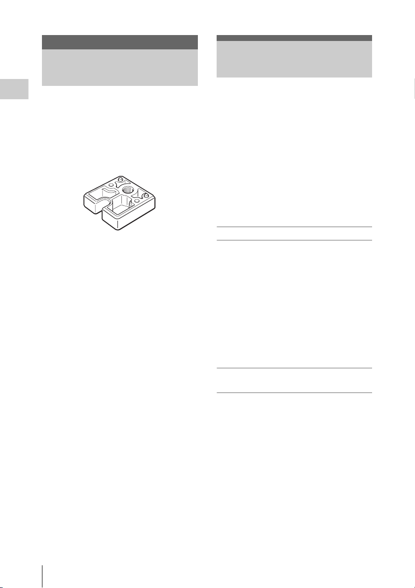
• Tripod adapter (1)
• Tripod adapter locking screws (2)
• Lens mount cap (1)
• Before Using This Unit (1)
•CD-ROM
(Instructions for Use in PDF format) (1)
• Warranty Booklet (1)
• Service Contact List (1)
This unit is a separated camera control unit-type
HD video camera consisting of a camera control
unit (CCU) and camera head equipped with a
1/2.9 type HD CMOS image sensor providing an
effective resolution of approximately 2.07
million pixels (1920 × 1080).
This camera lets you shoot HD images with 1,080
effective scanning lines in progressive format,
allowing you to capture details and movement in
videos with greater clarity than in interlaced
format.
Additionally, synchronized operation of two of
these units allows you to shoot 3D videos.
Cutting-edge camera technologies
1/2.9 type Exmor CMOS sensor
Equipped with an Exmor CMOS sensor, this
camera allows shooting in Full HD.
Compact, lightweight camera head
The camera head is compact (approx. 27 × 28 ×
49 mm (approx. 1
lightweight (approx. 40 g (approx. 1.4 oz.)),
making it easy to install and attach anywhere.
The camera cable (not supplied) between the
camera head and camera control unit can be
extended to up to 20 m (65.6 ft.).
1
/8 × 1 1/8 × 1 15/
in.)), and
16
Shooting modes for diverse imaging
applications
Package Configuration / Features of This Unit
14
Picture profile function
This function allows the camera operator to easily
call up customized picturetonal settings to suit
particular shooting conditions. You can register
up to six picture profiles.
Picture flip
You can flip the camera picture output
horizontally, vertically, or both horizontally and
vertically.
Freeze function (still image)
You can freeze the video signal and output it as a
still image.

Two-camera support for 3D shooting
Using the built-in 3D-SYNC IN/OUT
connectors, you can synchronize the image
signals from two cameras to shoot 3D images.
Intuitive control via the front panel
The BRIGHTNESS, RED, and BLUE knobs on
the front panel provide an intuitive way to adjust
the picture. When turned to the right they increase
their respective values (brightening the picture or
strengthening colors), and when turned to the left
they decrease their values (darkening the picture
or weakening colors).
Overview
Features of This Unit
15
Part Names and Functions
See the pages enclosed in parentheses for details
Overview
about the corresponding function and how to use it.
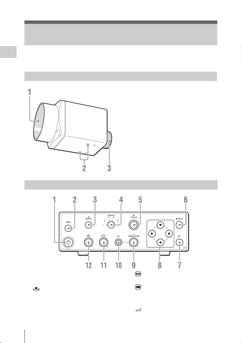
Camera head
Camera control unit (CCU) front panel
1. Lens mount (page 19)
Use this to mount a C-mount lens, microscope
adapter, etc.
2. Screw holes (M3, depth: 2.5 mm (1/8
inch))
Use these holes to attach the supplied tripod
adapter to the camera head for mounting it on a
wall, ceiling or tripod.
3. Camera cable connector (20 pin) (page 20)
1. 1 (on/standby) button (page 23)
2. BARS (color bars) button (page 32)
3. WHITE (white balance) button (page
27)
4. PROFILE (Picture Profile selection)
button (page 32)
Part Names and Functions
16
5. FREEZE (still image) button (page
31)
6. MENU button (page 38)
7. SET (confirm) button (page 38)
8. V/v /B/b (cursor) button (page 38)
9. BRIGHTNESS (brightness
adjustment) knob (page 30)
10. AE (automatic exposure) button (page 30)
11. BLUE (B-gain) knob (page 28)
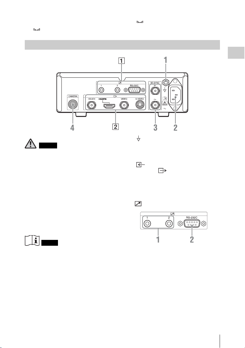
Camera control unit (CCU) rear panel
Warning
Using this unit for medical purposes
This equipment’s connectors are not isolated.
Do not connect any device other than one which
conforms to IEC60601-1.
When an information technology device or AV
device that uses an alternating current is
connected, current leakage may result in an
electric shock to the patient or operator.
If use of such a device is unavoidable, isolate its
power supply by connecting an isolation
transformer, or by connecting an isolator between
the connecting cables.
After implementing these measures, confirm that
the reduced risk now conforms to IEC60601-1.
12. RED (R-gain) knob (page 28)
Overview
1. Equipotential ground connector
Used to make an equipotential ground
connection.
2. - (power) connector (page 23)
3. 3D-SYNC IN (3D-SYNC input)
connector, 3D-SYNC OUT (3DSYNC output) connector (BNC type)
(page 47)
4. CAMERA connector (page 20)
1 REMOTE connector block
Caution
Do not come into contact with the terminals of the
rear panel connectors and patients at the same
time.
Doing so may result in a generation of voltage
that can be harmful to patients if the unit is
malfunctioning. Always disconnect the power
cord before connecting and disconnecting
connectors.
1. Remote contact switch connector 1, 2
(stereo mini jack) (page 46)
2. RS-232C connector (D-sub 9-pin) (page
48)
Part Names and Functions
17
 Loading...