

Sony MCC-3000MT Instructions For Use Manual

4-430-312-12 (1)
3D HD Video Camera
Instructions for Use
Before operating the unit, please read this manual thoroughly
and retain it for future reference.
MCC-3000MT
© 2012 Sony Corporation
WARNING
To reduce the risk of fire or
electric shock, do not expose this
apparatus to rain or moisture.
To avoid electrical shock, do not
open the cabinet. Refer servicing
to qualified personnel only.
No modification of this equipment is allowed.
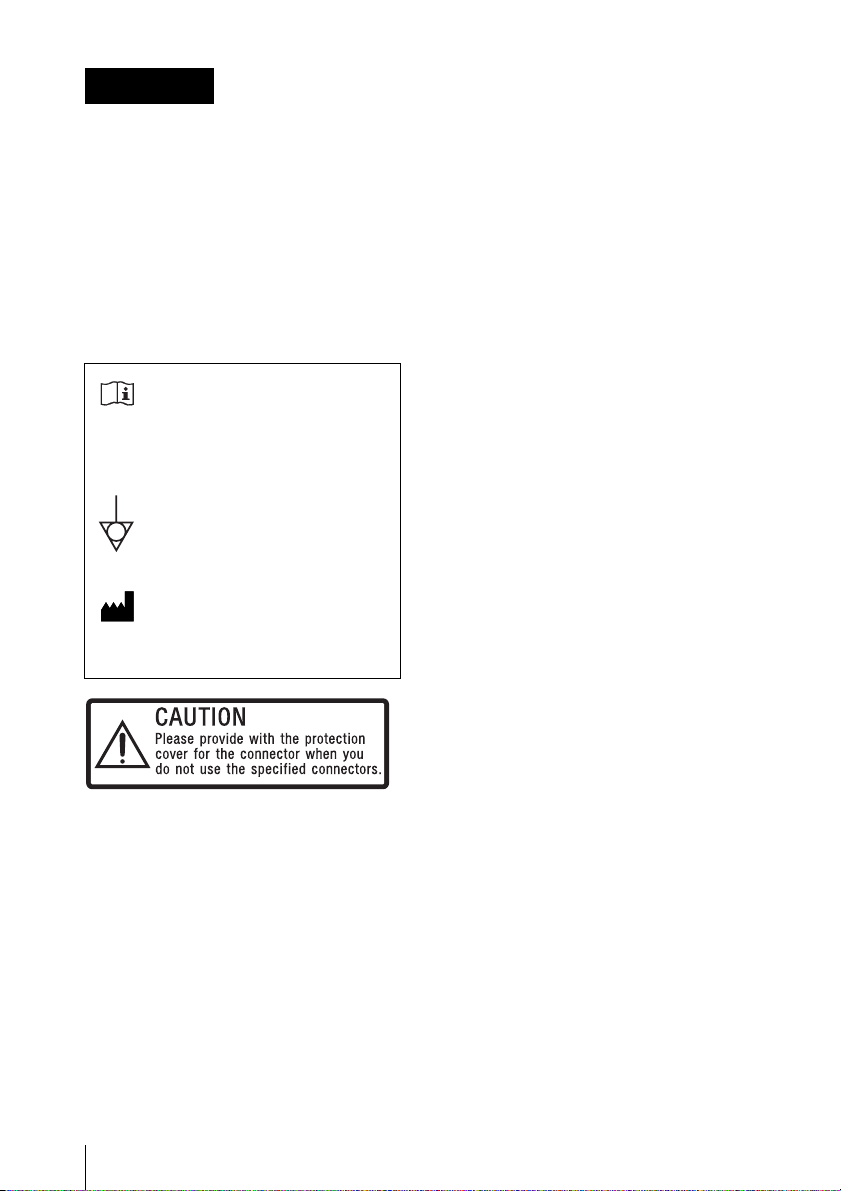
Symbols on the products
Refer to the operating instructions
Follow the directions in the
operating instructions for parts of
the unit on which this mark
appears.
This symbol indicates the
equipotential terminal which brings
the various parts of a system to the
same potential.
This symbol indicates the
manufacturer, and appears next to
the manufacturer’s name and
address.
manual, may cause harmful interference to
radio communications. Operation of this
equipment in a residential area is likely to
cause harmful interference in which case the
user will be required to correct the
interference at his own expense.
You are cautioned that any changes or
modifications not expressly approved in this
manual could void your authority to operate
this equipment.
All interface cables used to connect
peripherals must be shielded in order to
comply with the limits for a digital device
pursuant to Subpart B of Part 15 of FCC
Rules.
This device complies with Part 15 of the FCC
Rules. Operation is subject to the following
two conditions: (1) this device may not cause
harmful interference, and (2) this device must
accept any interference received, including
interference that may cause undesired
operation.
For the customers in Canada
This Class A digital apparatus complies with
Canadian ICES-003.
For the customers in Canada
This unit has been certified according to
Standard CAN/CSA-C22.2 No.60601-1.
This label is located on the top panel of the
unit.
See page 18 of these instructions for details
about how to attach the connector covers.
For the customers in the U.S.A.
This equipment has been tested and found to
comply with the limits for a Class A digital
device, pursuant to Part 15 of the FCC Rules.
These limits are designed to provide
reasonable protection against harmful
interference when the equipment is operated
in a commercial environment. This
equipment generates, uses, and can radiate
radio frequency energy and, if not installed
and used in accordance with the instruction
2
Important safeguards/notices for use in the
medical environments
1. All the equipments connected to this unit
shall be certified according to Standard
IEC60601-1, IEC60950-1, IEC60065 or
other IEC/ISO Standards applicable to
the equipments.
2. Furthermore all configurations shall
comply with the system standard
IEC60601-1-1. Everybody who connects
additional equipment to the signal input
part or signal output part configures a
medical system, and is therefore,
responsible that the system complies
with the requirements of the system
standard IEC60601-1-1.
If in doubt, consult the qualified service
personnel.
3. The leakage current could increase
when connected to other equipment.

4. For this particular equipment, all
accessory equipment connected as
noted above, must be connected to
mains via an additional isolation
transformer conforming with the
construction requirements of IEC606011 and providing at least Basic Insulation.
5. This equipment generates, uses, and
can radiate radio frequency energy. If it is
not installed and used in accordance with
the instruction manual, it may cause
interference to other equipment. If this
unit causes interference (which can be
determined by unplugging the power
cord from the unit), try these measures:
Relocate the unit with respect to the
susceptible equipment. Plug this unit and
the susceptible equipment into different
branch circuit.
Consult your dealer. (According to standard
EN60601-1-2 and CISPR11, Class B,
Group 1)
3
Important EMC notices for use in the medical environments
• The MCC-3000MT needs special precautions regarding EMC and needs to be installed and
put into service according to the EMC information provided in this instructions for use.
• The portable and mobile RF communications equipment such as cellular phones can affect the
MCC-3000MT.
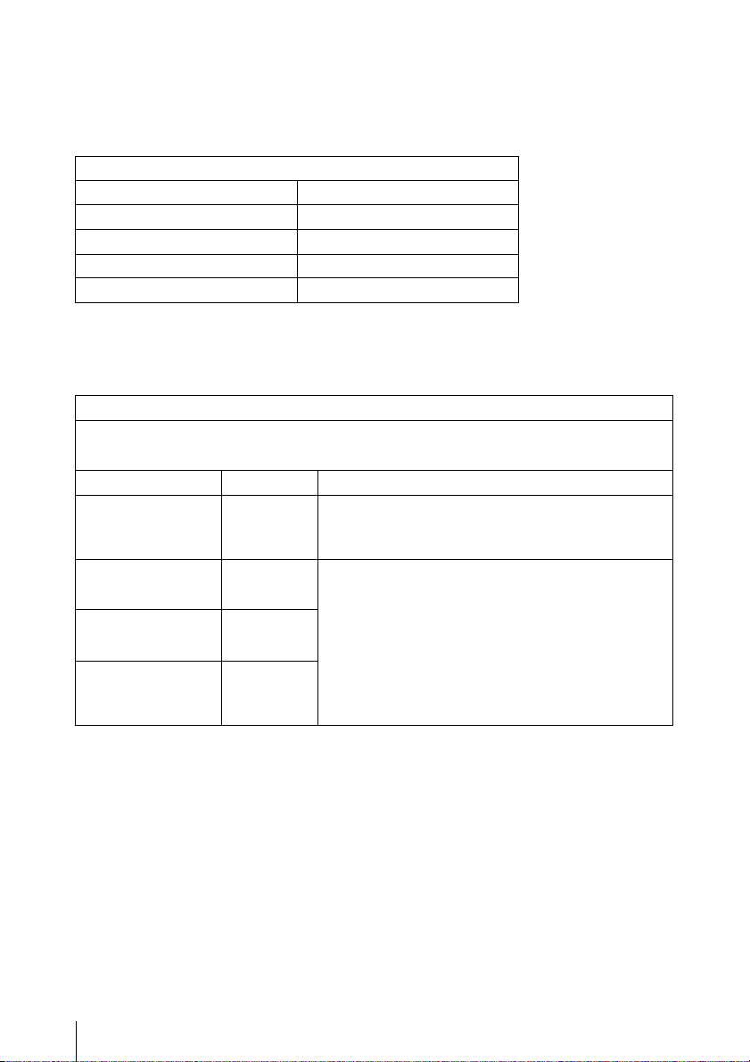
List of cables used for EMC tests
Type of cable Specifications
DC power cable 1.5 m, non-shielded
CCMC-T15 camera cable 15 m, shielded
BNC Cable (5C-FW) 1.5 m, shielded
D-Sub 9P Cable (RS232C) 1.5 m, shielded
Warning
The use of accessories and cables other than those specified, with the exception of replacement
parts sold by Sony Corporation, may result in increased emissions or decreased immunity of the
MCC-3000MT.
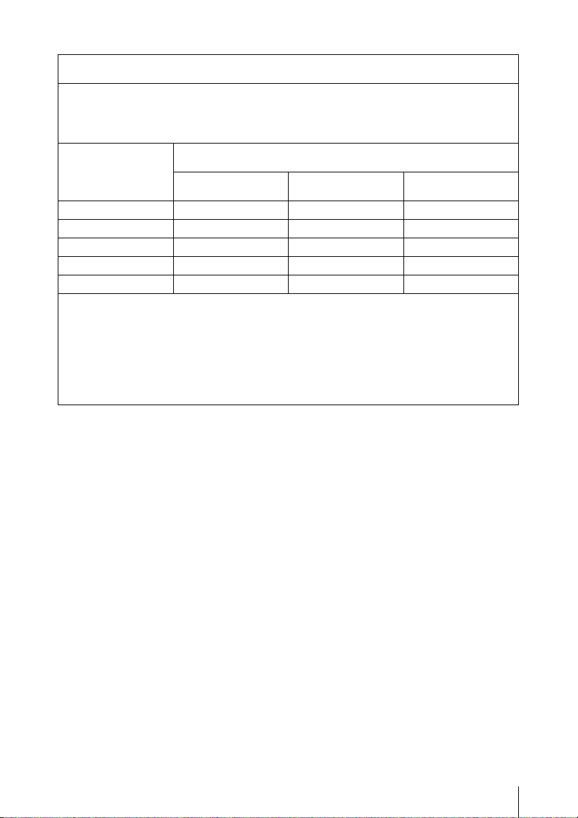
Guidance and manufacturer’s declaration - electromagnetic emissions
MCC-3000MT is intended for use in the electromagnetic environment specified below.
The
The customer or the user of the MCC-3000MT should assure that it is used in such an
environment.
Emission test Compliance Electromagnetic environment-guidance
RF emissions
CISPR 11
RF emissions
CISPR 11
Harmonic emissions
IEC 61000-3-2
Voltage fluctuations/
flicker emissions
IEC 61000-3-3
Group 1 The
Class B The
Class A
Complies
function. Therefore, its RF emissions are very low and
are not likely to cause any interference in nearby
electronic equipment.
establishments, including domestic establishments and
those directly connected to the public low-voltage power
supply network that supplies buildings used for domestic
purposes.
MCC-3000MT uses RF energy only for its internal
MCC-3000MT is suitable for use in all
4
Warning
If the MCC-3000MT should be used adjacent to or stacked with other equipment, it should be
observed to verify normal operation in the configuration in which it will be used.
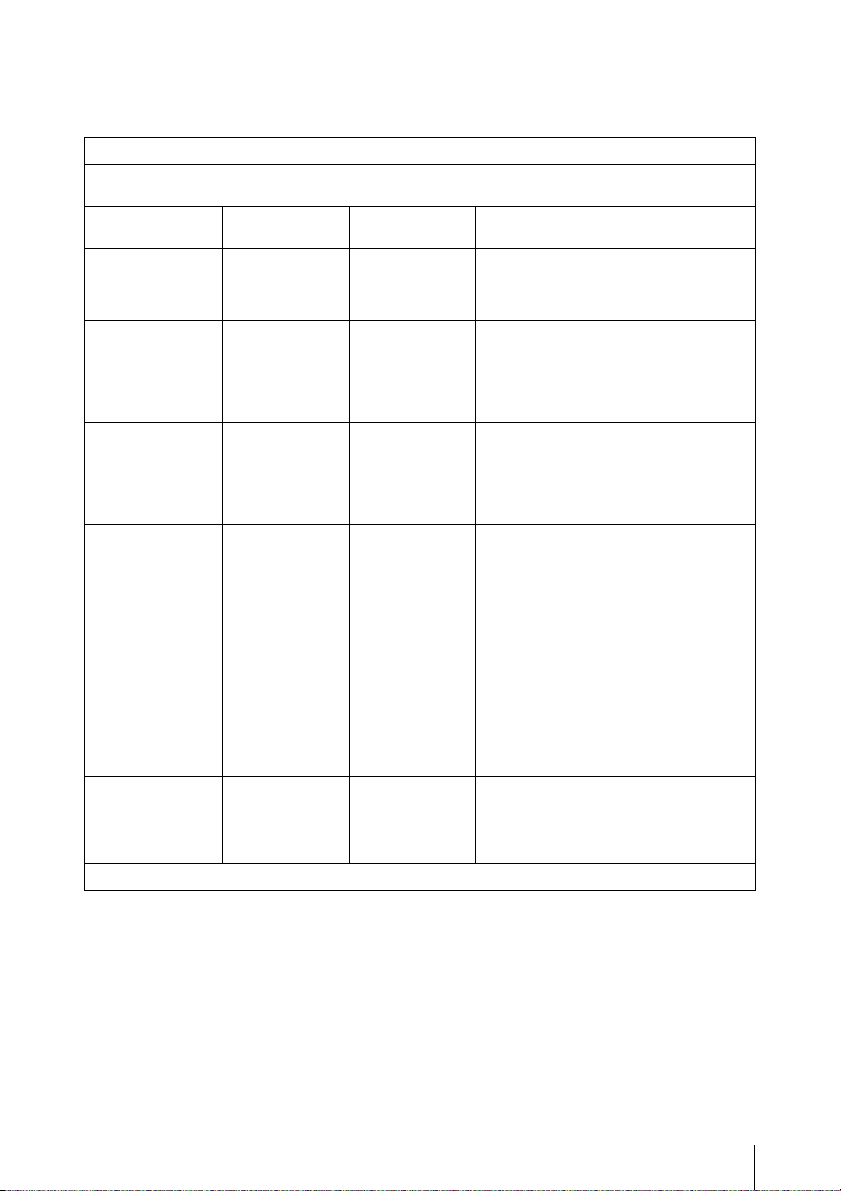
Guidance and manufacturer’s declaration - electromagnetic immunity
MCC-3000MT is intended for use in the electromagnetic environment specified below. The
The
customer or the user of the MCC-3000MT should assure that it is used in such as environment.
Immunity test IEC 60601
Electrostatic
discharge (ESD)
IEC 61000-4-2
Electrical fast
transient/burst
IEC 61000-4-4
Surge
IEC 61000-4-5
Voltage dips,
short
interruptions and
voltage
variations on
power supply
input lines
IEC 61000-4-11
Power frequency
(50/60Hz)
magnetic field
test level
±6 kV contact
±8 kV air
±2 kV for
power supply
lines
±1 kV for input/
output lines
±1 kV
differential
mode
±2 kV common
mode
< 5% U
(> 95% dip in
U
) for 0.5
T
cycle
40% U
(60% dip in U
for 5 cycles
70% U
(30% dip in U
for 25 cycles
< 5% U
(> 95% dip in
U
) for 5 sec
T
3 A/m 3 A/m Power frequency magnetic fields
IEC 61000-4-8
NOTE: U
is the a.c. mains voltage prior to application of the test level.
T
T
T
T
T
±6 kV contact
±8 kV air
±2 kV for
power supply
lines
±1 kV for input/
output lines
±1 kV
differential
mode
±2 kV common
mode
< 5% U
(> 95% dip in
U
cycle
40% U
(60% dip in U
)
T
for 5 cycles
70% U
(30% dip in U
)
T
for 25 cycles
< 5% U
(> 95% dip in
U
Compliance
level
T
) for 0.5
T
T
T
T
) for 5 sec
T
Electromagnetic environment -
Floors should be wood, concrete or
ceramic tile. If floors are covered with
synthetic material, the relative humidity
should be at least 30%.
Mains power quality should be that of
a typical commercial or hospital
environment.
Mains power quality should be that of
a typical commercial or hospital
environment.
Mains power quality should be that of
a typical commercial or hospital
environment. If the user of the
MCC-3000MT requires continued
operation during power mains
interruptions, it is recommended that
the
)
T
T
MCC-3000MT be powered from
an uninterruptible power supply or a
battery.
)
should be at least characteristic of a
typical location in a typical commercial
or hospital environment.
guidance
5
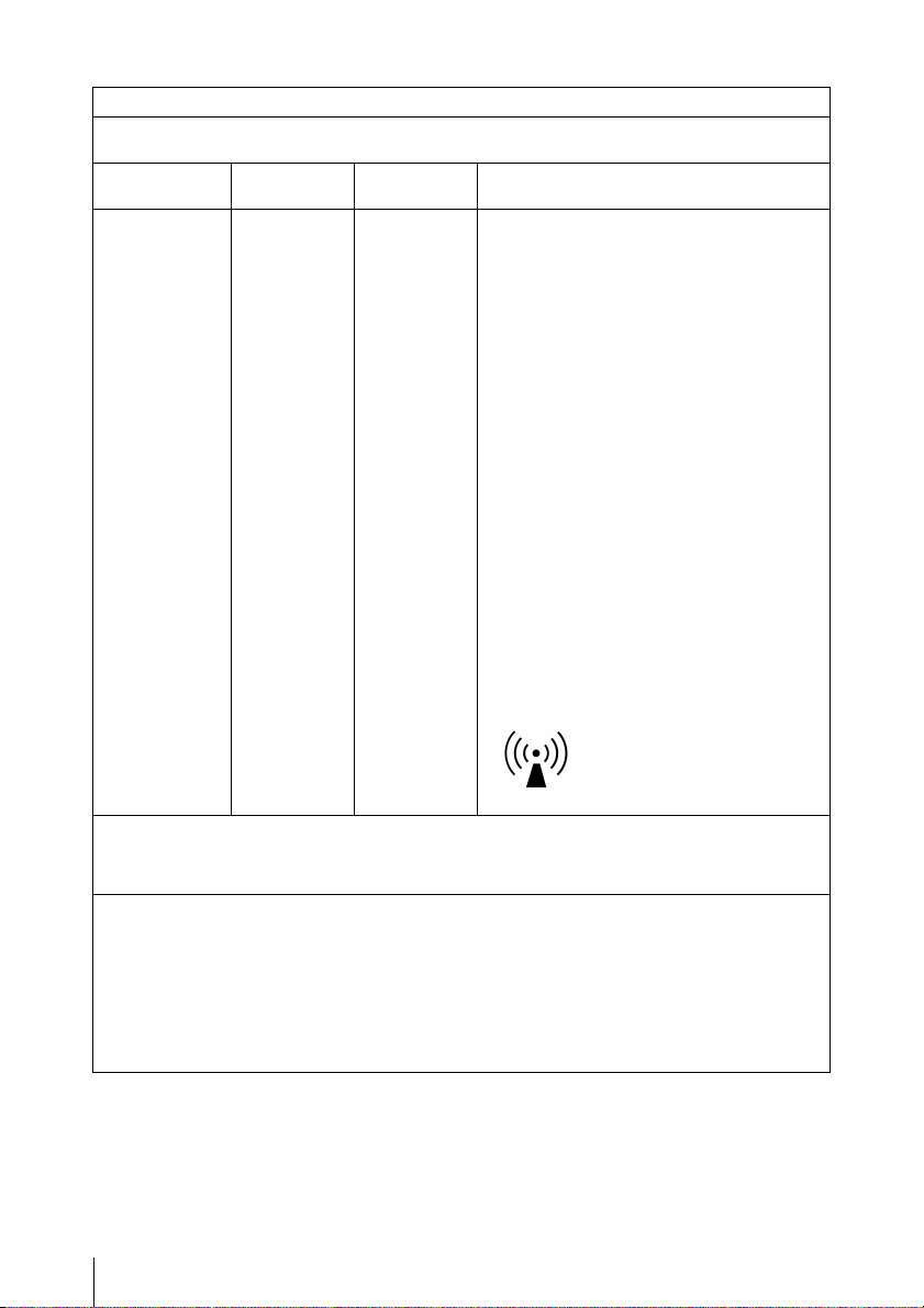
Guidance and manufacturer’s declaration - electromagnetic immunity
The
MCC-3000MT is intended for use in the electromagnetic environment specified below. The
customer or the user of the
Immunity test IEC 60601
Conducted RF
IEC 61000-4-6
Radiated RF
IEC 61000-4-3
MCC-3000MT should assure that it is used in such as environment.
test level
3 Vrms
150 kHz to
80 MHz
3 V/m
80 MHz to
2.5 GHz
Compliance
level
3 Vrms
3 V/m
Electromagnetic environment - guidance
Portable and mobile RF communications
equipment should be used no closer to any
part of the
than the recommended separation distance
calculated from the equation appliance to the
frequency of the transmitter.
Recommended separation distance
d = 1.2√P
d = 1.2√P 80 MHz to 800 MHz
d = 2.3√P 800 MHz to 2.5 GHz
Where P is the maximum output power rating
of the transmitter in watts (W) according to
the transmitter manufacturer and d is the
recommended separation distance in meters
(m).
Field strengths from fixed RF transmitters, as
determined by an electromagnetic site
survey,
level in each frequency range. b
Interference may occur in the vicinity of
equipment marked with following symbol:
MCC-3000MT, including cables,
a
should be less than the compliance
NOTE 1: At 80 MHz and 800 MHz, the higher frequency range applies.
NOTE 2: These guidelines may not apply in all situations. Electromagnetic propagation is affected
a Field strengths from fixed transmitters, such as base stations for radio (cellular/cordless)
b Over the frequency range 150 kHz to 80 MHz, field strengths should be less than 3 V/m.
by absorption and reflection from structures, objects and people.
telephones and land mobile radios, amateur radio, AM and FM radio broadcast and TV
broadcast cannot be predicted theoretically with accuracy. To assess the electromagnetic
environment due to fixed RF transmitters, an electromagnetic site survey should be considered.
If the measured field strength in the location in which the MCC-3000MT is used exceeds the
applicable RF compliance level above, the MCC-3000MT should be observed to verify normal
operation. If abnormal performance is observed, additional measures may be necessary, such
as reorienting or relocating the MCC-3000MT.
6
Recommended separation distances between portable and
mobile RF communications equipment and the MCC-3000MT
The MCC-3000MT is intended for use in an electromagnetic environment in which radiated RF
disturbances are controlled. The customer or the user of the MCC-3000MT can help prevent
electromagnetic interference by maintaining a minimum distance between portable and mobile RF
communications equipment (transmitters) and the MCC-3000MT as recommended below,
according to the maximum output power of the communications equipment.
Rated maximum
output power of
transmitter
W
0.01 0.12 0.12 0.23
0.1 0.380.380.73
1 1.2 1.2 2.3
10 3.8 3.8 7.3
100 12 12 23
For transmitters rated a maximum output power not listed above, the recommended separation
distance d in meters (m) can be estimated using the equation applicable to the frequency of the
transmitter, where P is the maximum output power rating of the transmitter in watts (W) according
to the transmitter manufacturer.
NOTE 1: At 80 MHz and 800 MHz, the separation distance for the higher frequency range
NOTE 2: These guidelines may not apply in all situations. Electromagnetic propagation is
applies.
affected by absorption and reflection from structures, objects and people.
Separation distance according to frequency of transmitter
150 kHz to 80 MHz
d = 1.2√P
m
80 MHz to 800 MHz
d = 1.2√P
800 MHz to 2.5 GHz
d = 2.3√P
CAUTION
When you dispose of the unit or accessories,
you must obey the laws in the relative area or
country and the regulations in the relative
hospital.
For the customers in Europe
Legal Representative for Medical Device
Directive
Sony Deutschland GmbH
Stuttgart Technology Center
Hedelfinger Strasse 61, D-70327 Stuttgart,
Germany
TEL: +49 (0) 711 5858 0
FAX: +49 (0) 711 5858 235
7

Table of Contents
Overview
Preparations
Package Configuration ............................................................ 11
Features..................................................................................... 11
Using the CD-ROM Manual ................................................... 12
Parts Identifications................................................................. 13
Camera head.................................................................. 13
Camera control unit (CCU) front panel ........................ 13
Menu operation block ................................................... 14
Camera control unit (CCU) rear panel .......................... 14
Lens Mounting ......................................................................... 16
Mounting the lens.......................................................... 16
Attaching the tripod adaptor.......................................... 16
Connection between the Camera Head and CCU................. 17
Connecting the camera cable to the camera head ......... 17
Connecting the camera cable to the CAMERA A/B
connector................................................................. 17
Removing the Connector Covers............................................ 18
Connecting Video Monitors .................................................... 19
Operating the Unit with a Computer..................................... 20
Start-up..................................................................................... 21
Turning the power off ................................................... 21
Output Format Settings........................................................... 22
Setting the output format............................................... 22
Output signal types........................................................ 22
Using genlock................................................................ 22
Screen Displays ........................................................................ 23
Shooting
Table of Contents
8
Basic Operation Procedure..................................................... 25
Shooting .................................................................................... 26
Adjusting the White Balance .................................................. 27
Selecting the adjustment mode...................................... 27

Executing auto white balance........................................ 27
Changing the color balance of the camera output
picture ..................................................................... 28
Adjusting the Brightness ......................................................... 29
Using the AE function................................................... 29
Using the BRIGHTNESS knob..................................... 30
Setting the total gain...................................................... 30
Setting the electronic shutter......................................... 30
Inverting the Camera Output Picture ................................... 31
Picture Profiles......................................................................... 32
Registering and recalling picture profiles ..................... 32
Copying the settings of a picture profile....................... 32
Resetting a picture profile ............................................. 33
Renaming a picture profile name .................................. 33
Picture profile items...................................................... 34
Menu Configuration and Detailed Settings
Overview of the Setup Menus................................................. 38
Setup menu configuration ............................................. 38
Setup menu layers ......................................................... 38
Basic Menu Operations ........................................................... 38
Setup Menu List....................................................................... 40
CAMERA SET menu.................................................... 40
VIDEO SET menu ........................................................ 41
OTHERS menu ............................................................. 41
Appendixes
Important Notes on Operation ............................................... 42
Troubleshooting ....................................................................... 44
Operating power............................................................ 44
Shooting ........................................................................ 44
Other troubles................................................................ 44
Error/Warning Indications..................................................... 45
Error indications............................................................ 45
Warning indications ...................................................... 45
Specifications............................................................................ 46
General .......................................................................... 46
Camera head.................................................................. 46
Inputs/outputs (camera control unit) ............................. 46
Optional accessories...................................................... 47
Table of Contents
9

GNU GPL Licensed Software................................................. 48
GNU GENERAL PUBLIC LICENSE ................................... 48
Preamble........................................................................ 48
TERMS AND CONDITIONS FOR COPYING,
DISTRIBUTION AND MODIFICATION............. 49
END OF TERMS AND CONDITIONS................................. 52
How to Apply These Terms to Your New Programs .... 52
Index.......................................................................................... 54
Table of Contents
10
Sony, and Exmor are trademarks of Sony Corporation.
Adobe and Adobe Reader are trademarks of Adobe Systems Incorporated in the
United States and/or other countries.
All other trademarks are the property of their respective owners.
Overview
Package Configuration
Features
Overview
Make sure the following items are supplied with
the Sony MCC-3000MT 3D HD Video Camera
(hereafter referred to as the “unit”).
The number in parentheses indicates the number
of that item supplied.
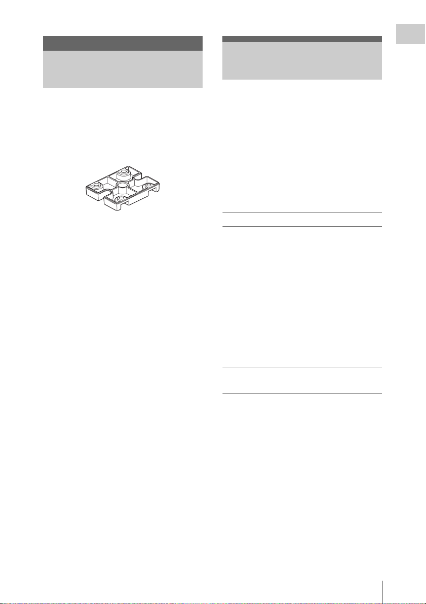
• Tripod adapter (2)
• Tripod adapter fitting screws (8)
• Lens mount cap (2)
• Operating Instructions
– Japanese version (1)
– English version (1)
– German version (1)
• Before Using This Unit (1)
•CD-ROM
– Manuals for 3D HD Video Camera
(Operating Instructions in PDF) (1)
• Warranty Booklet (1)
• Service Contact List (1)
This unit is a 3D-compatible camera system
consisting of a separated camera control unit
(CCU) and two camera heads equipped with 1/2inch HD CMOS image sensors, each providing an
effective resolution of approximately 2.07
million pixels (1920 × 1080).
The system allows you to shoot HD images with
1080 effective scanning lines in interlaced mode.
In addition, appropriate setup and synchronized
operation of the two camera heads allows you to
shoot 3D images.
Cutting-edge camera technologies
Three 1/2-inch type “Exmor” CMOS sensors
Equipped with three 1/2-inch “Exmor” CMOS
Sensors, the system allows shooting in full HD
resolution.
Compact, lightweight camera head
The camera head is compact (35 × 45 × 50 mm
7
(1
/16 × 113/
(90 g (3.2 oz)), making it easy to install and attach
anywhere.
The separately sold camera cables allow you to
use the camera head up to 20 m (66 feet) away
from the camera control unit.
× 2 inches)) and lightweight
16
Shooting modes for diverse imaging
applications
Picture inversion
You can invert the camera output picture
horizontally, vertically, or both horizontally and
vertically.
Selectable gamma curves
This unit provides various types of gamma curves
prepared depending on scenes.
Camera selection
When configuring image settings, simply press
the selection button on the front panel to select
either camera or both for fast image
synchronization.
Package Configuration / Features
11

3D image output to external equipment
Overview
The system’s two HD SDI output connectors
allow you to output image signals from camera A
and camera B.
Using the CD-ROM Manual
Convenient functions and intuitive
operation
Picture Profile feature
The Picture Profile feature allows the camera
operator to easily call up customized picturetonal settings to suit particular shooting
conditions.
You can register up to six of these.
Downconvert function
You can downconvert HD signals for output,
enabling integration with SD systems.
Note
When signals are downconverted to SD, a slight
distortion may occur in the image for a few
seconds.
RS-232C interface
The unit is equipped with an RS-232C interface,
allowing it to be controlled from a computer.
For details, contact your Sony dealer or your Sony
service representative.
Intuitive operations on front panel
The BRIGHTNESS, RED, and BLUE knobs on
the front panel provide an intuitive way to adjust
the picture. When rotated to the right, they
increase their respective values (giving a brighter
picture or stronger colors), and when rotated to
the left they decrease their values (giving a darker
picture or weaker colors).
Setup menu configurations and other settings can
also be performed in the front panel display.
The manual can be read on a computer with
Adobe Reader installed.
You can download Adobe Reader free from the
Adobe website.
1 Open the index.html file in the
CD-ROM.
2 Select and click on the manual that you
want to read.
Note
If you have lost or damaged the CD-ROM, you
can purchase a new one from your Sony dealer or
Sony service counter.
Using the CD-ROM Manual
12
Parts Identifications
See the pages enclosed in parentheses ( ) for
details about the corresponding function and how
to use it.
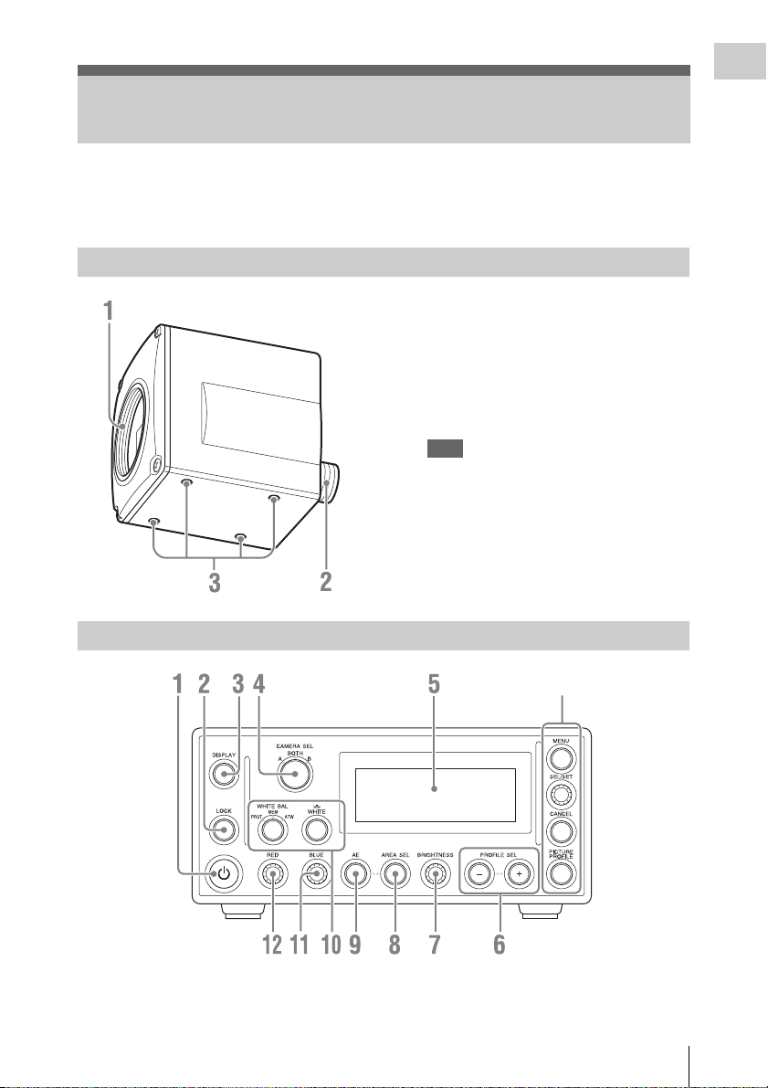
Camera head
1. Lens mount (page 16)
2. Camera cable connector (20-pin) (page 17)
3. Screw holes (M3, depth: 2.5 mm (
inches))
Use these holes to attach the supplied tripod
adaptor to the camera head for mounting it on
a wall, ceiling or tripod.
Note
For extended shooting sessions, we
recommend using the supplied tripod adaptor
and stabilizing the camera head on a tripod.
1
/8
Overview
Camera control unit (CCU) front panel
Menu operation block (page 14)
1. On/Standby button (1) (page 21) 2.LOCK button
Inhibits actions of the other buttons and
knobs.
Parts Identifications
13
3. DISPLAY button (page 23)
Overview
4. CAMERA SEL (camera selection) button
(page 26)
5. Front panel display (page 23)
6. PROFILE SEL (profile selection) + and –
buttons (page 32)
7. BRIGHTNESS knob (page 30)
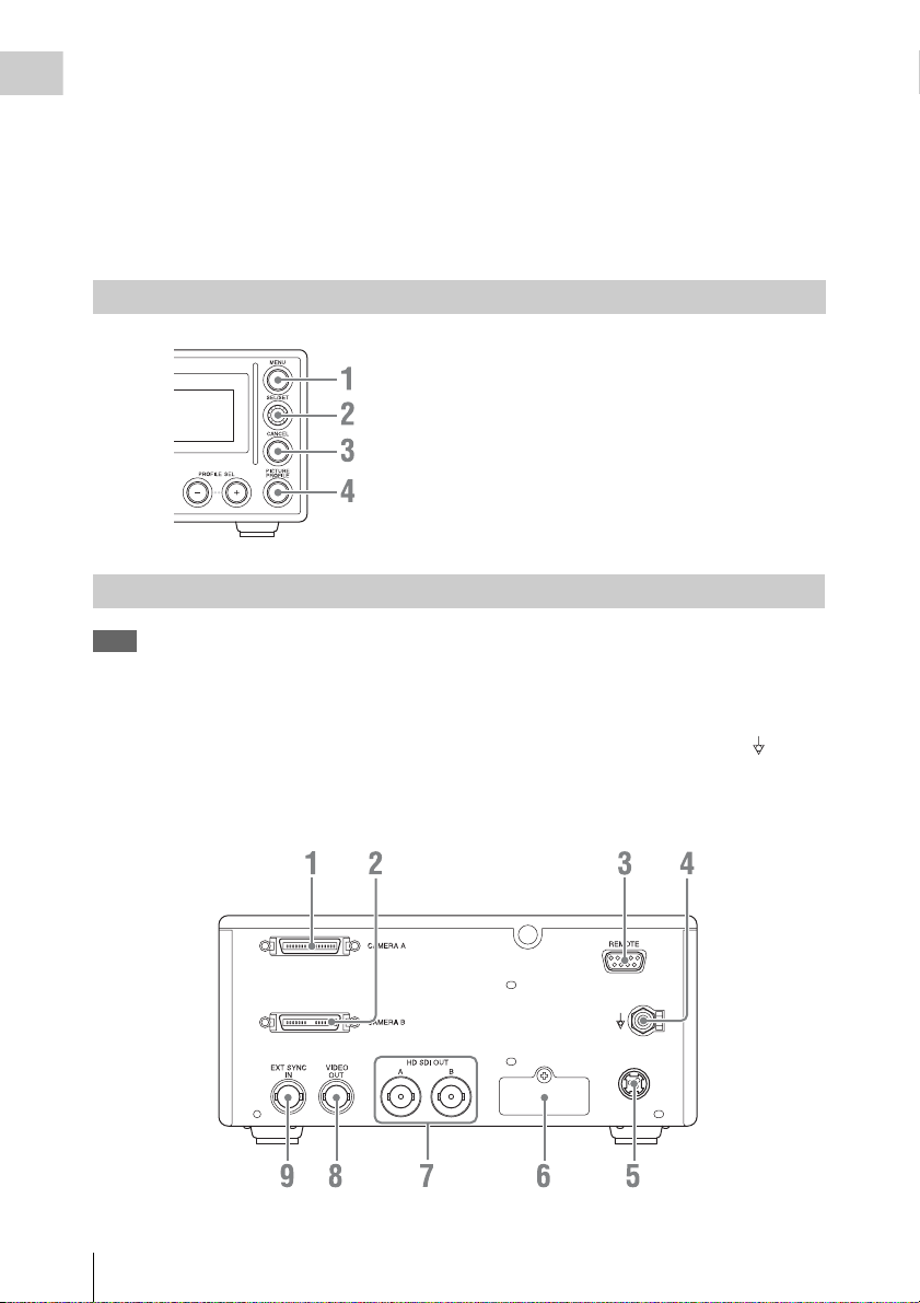
Menu operation block
Camera control unit (CCU) rear panel
8. AREA SEL (light measurement area
selection) button (page 29)
9. AE (automatic exposure) button (page 29)
10. White balance adjustment section (page
27)
11. BLUE (blue gain) knob (page 28)
12. RED (red gain) knob (page 28)
1. MENU button (page 38)
2. SEL/SET knob (page 38)
3. CANCEL button (page 38)
4. PICTURE PROFILE button (page 32)
Note
When the unit is shipped from the factory,
connector covers are attached to the following
connectors.
• HD SDI OUT A, B
• EXT SYNC IN
• VIDEO OUT
To use one of these connectors, remove the cover
(see page 18).
Parts Identifications
14
1. CAMERA A connector (page 17)
2. CAMERA B connector (page 17)
3. REMOTE connector (D-sub 9-pin, RS-
232C) (page 20)
4. Equipotential ground terminal ( )
Use to make an equipotential ground
connection.

5. DC IN (DC power input) connector
Use a Hosiden connector for connection.
Connector name: TCP8927-53
Cable material: Voltage rating of 60 V or
higher and allowable current of 7 A or higher
is recommended.
Overview
DC 24 V
(1.5 A to 3 A)
NC
GND
6. Service USB port
7. HD SDI OUT (HD SDI output) A, B
connectors (BNC) (page 19)
8. VIDEO OUT (composite video output)
connector (BNC) (page 19)
9. EXT SYNC IN (external synchronization
signal input) connector (BNC) (page 22)
Parts Identifications
15
Preparations
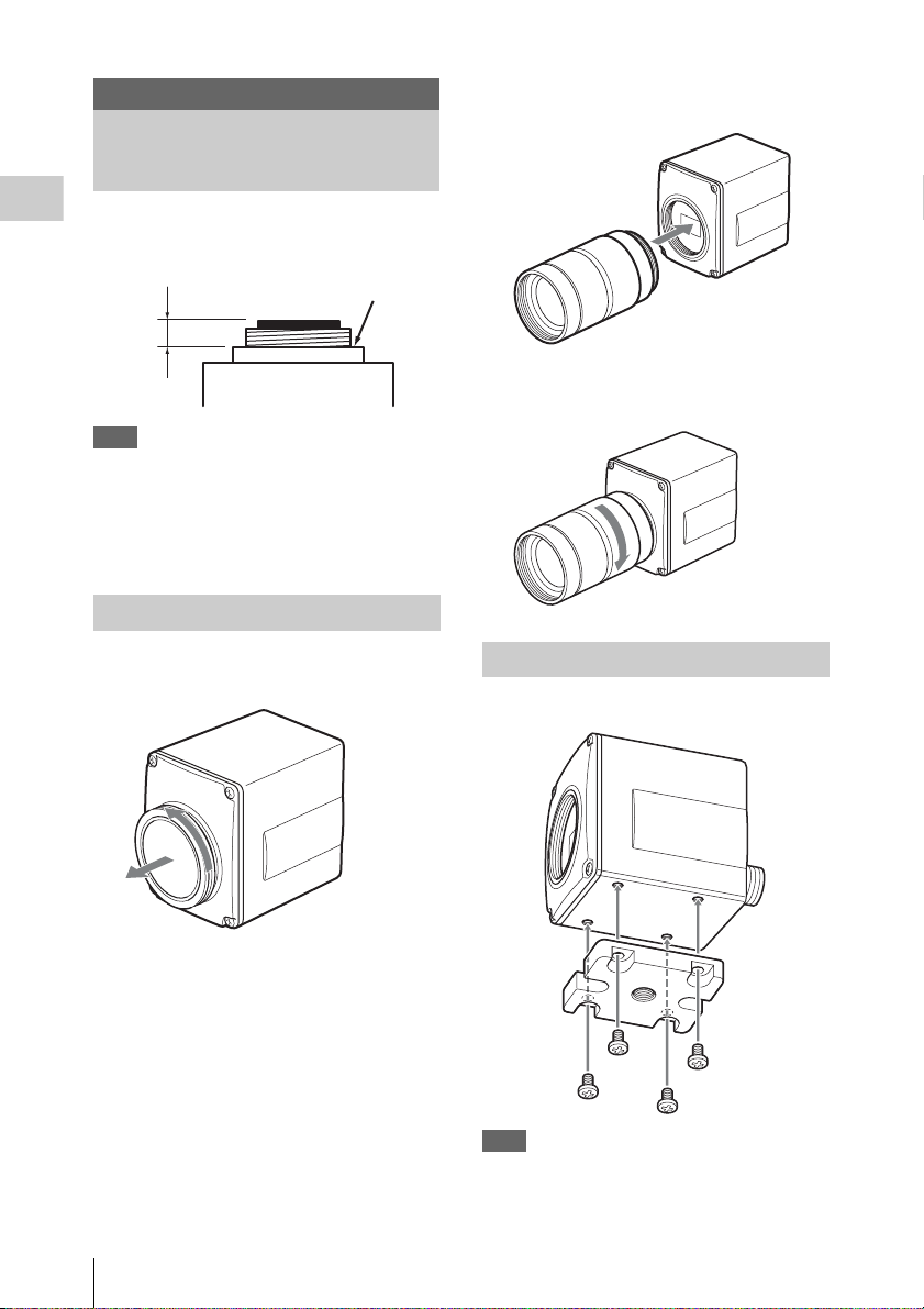
Lens Mounting
C-mount lenses with the following lens mount
Preparations
surface can be attached to the camera head.
Lens mount surface
4.1 mm
or less
Note
Be sure to use a lens whose projected part from
the lens mount surface is 4.1 mm (
less. Mounting the lens with a maximum
projection part 4.2 mm or more may damage the
internal mechanism of the camera head.
Mounting the lens
3
2 Align the threaded portion of the lens
mount with that of the camera mount.
3 Slowly rotate the lens clockwise to fix
the lens to the camera head tightly.
/16 inches) or
1 Remove the lens mount cap of the
camera head.
Lens Mounting
16
Attaching the tripod adaptor
Attach the supplied tripod adaptor if necessary.
Note
When using a heavy lens, support the lens itself.
Do not support the lens via the camera head alone.
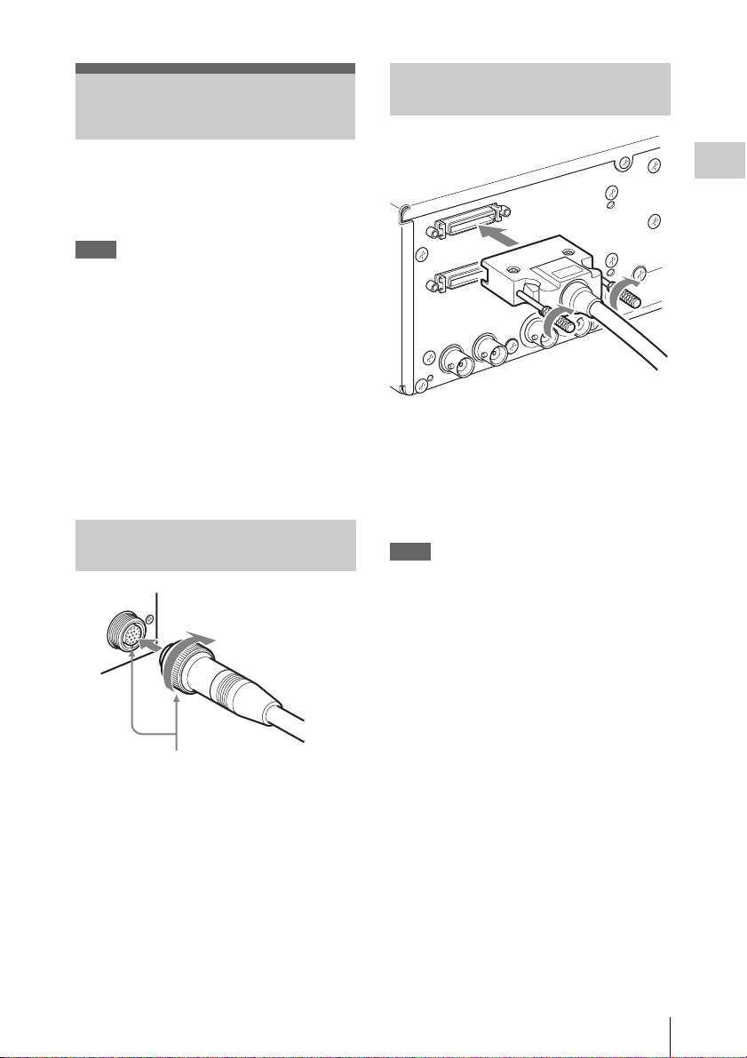
Connection between the Camera Head and CCU
Connecting the camera cable to the CAMERA A/B connector
Connect the camera cable connector on the
camera head with the CAMERA A/B connector
on the CCU using the optional CCMC-T05/T10/
T20 Camera Cable.
Notes
• Be sure to turn off the power supply for all
equipment when you connect or disconnect the
camera cable. Connecting/disconnecting a
cable while the power is on may result in
malfunctions.
• Be sure to connect the camera head and CCU
with the camera cable before you start the unit.
• Insert the connector by pushing it straight in,
being careful not to bend the pins.
• Insert the connectors of the cables properly.
Loose connection often generates noise. When
pulling out a cable, be sure to pull it out by the
connector, not the cable itself.
Connecting the camera cable to the camera head
Connector ring
Preparations
1 Connect the camera cable square plug
to the CAMERA A connector.
2 Tighten the two screws on the square
plug.
Connect the camera cable to the CAMERA B
connector in the same way.
Notes
• Excessive tightening the screws may make
them difficult to loosen and result in damage.
• Turning the screws with your hands until the
screws do not move is sufficient. Do not use
tools or excessive force when tightening the
screws.
Positioning marks
1 Align the positioning marks on the
camera cable connector and on the
camera cable round plug, and then push
the plug in.
2 Turn the connector ring to tighten.
Connection between the Camera Head and CCU
17
 Loading...