

Sony MB-806A Operating Instructions Manual
Tuner Base Unit
3-867-235-23(1)
Operating Instructions
Bedienungsanleitung
Wireless Channel Lists/Übertragungskanallisten
GB
DE
MB-806A
1999 Sony Corporation [CE] [AU]

English
WARNING
To prevent fire or shock hazard, do not
expose the unit to rain or moisture.
To avoid electrical shock, do not open the
cabinet. Refer servicing to qualified
personnel only.

Table of Contents
Precautions....................................................... 1
Overview ........................................................... 2
Features ............................................................. 2
System Configuration........................................ 3
Channel Plan ..................................................... 3
Location of Parts and Controls....................... 4
Front Panel ........................................................ 4
Display .............................................................. 4
Rear Panel ......................................................... 5
Installing a WRU-806A/WRU-806B
Tuner Unit..................................................... 6
Precautions
Connections ..................................................... 7
Basic Connections ............................................. 7
Connection for Multichannel Operation ........... 7
Channel Setting................................................ 8
Automatic Search and Setting of Available
Channels....................................................... 9
Operation ........................................................ 11
Muting Functions ............................................ 12
Error Messages .............................................. 13
Rack Mounting ............................................... 13
Specifications................................................. 14
Wireless Channel Lists................................. L-1
GB
English
On operation
•The tuner must be used within a temperature range of
0°C to 40°C. Avoid using the tuner for extended
periods at extremely high temperatures or placing it
in direct sunlight, especially outdoors, because this
may damage the finish of the case. Never install the
tuner on or near a heat source, such as lighting
equipment or power amplifiers.
•Avoid using in very humid or dusty places, because
such use may shorten the life of the tuner.
•To avoid degradation of the signal-to-noise ratio, do
not use the tuner in noisy places or in locations
subject to vibration, such as the following:
– near electrical equipment, such as motors,
transformers or dimmers
– near air conditioning equipment or places subject
to direct air flow from an air conditioner
– near public address loudspeakers
–where adjacent equipment might knock against the
tuner
•Switching lights on or off may produce electrical
interference over the entire frequency range. Position
the tuner and the wireless microphones so that
interference is minimized.
•The tuner is precisely adjusted at the factory and no
adjustment before use is necessary. Do not touch the
inside of the tuner or try to repair it by yourself.
On cleaning
Clean the tuner with a dry, soft cloth. Never use
thinner, benzene, alcohol or any other chemicals, since
these may damage the finish.
1(GB)

Overview
These operating instructions describe the MB-806A
Tuner Base Unit in which the optional WRU-806A/
WRU-806B UHF Synthesized Tuner Unit is installed.
The unit is a reliable UHF synthesized diversity tuner
for the Sony UHF wireless microphone system which
uses the frequency bands allocated for UHF TV
broadcasting.
This tuner is designed to enable simultaneous use of
multiple channels when channels are selected
according to the channel plan.
Installing six WRU-806A/WRU-806B UHF
Synthesized Wireless Tuner Units will enable sixchannel operation on the tuner.
In building up a UHF wireless microphone system, be
sure to combine a microphone/transmitter and a tuner
having the same TV channel number.
WRU-806B/CE57, CE62, and CE67 models
A 24-MHz frequency band is assigned to the MB806A with WRU-806B, permitting it to operate on any
of 189 receiving frequencies in 125-kHz steps of Sony
original channel plan or 960 receiving frequencies in
25-kHz steps in the range of three TV channels.
The selectable channels and frequencies for these models
are listed on the “Wireless Microphone System Frequency
List” supplied with the WRU-806B.
WRU-806A/CE62 model
A-14 MHz frequency band is assigned to the MB806A with WRU-806A (CE62) model, permitting it to
operate on any of 111 receiving frequencies in 125kHz steps of Sony original channel plan or 561
receiving frequencies in 25-kHz steps of German User
Group in the range of TV channels 62 and 63.
WRU-806A/AU66 model
An 14 MHz frequency band is assigned to the MB806A with WRU-806A (AU66) model, permitting it to
operate on any of 102 receiving frequencies in 125kHz steps of Sony original channel plan in the range of
TV channel 66 and 67.
The selectable wireless channels and frequencies for this
model are listed on pages L-10 and L-11.
Features
Phase Locked Loop (PLL) synthesized
system
The tuner has a refined phase locked loop (PLL)
synthesizer circuit.
Preprogrammed wireless channel plan for
simultaneous multichannel operation
The tuner has many preprogrammed, easily settable
channels for simultaneous multichannel operation.
Modular multichannel reception
By installing optional WRU-806A/WRU-806B UHF
Synthesized Tuner Units, you can receive up to six
channels on one MB-806A unit.
Versatile display
The selectable wireless channels and frequencies for this
model are listed pages L-3 through L-8.
WRU-806A/CE69 model
An 8-MHz frequency band is assigned to the MB806A with WRU-806A (CE69) model, permitting it to
operate on any of 64 receiving frequencies in 125-kHz
steps of Sony original channel plan in the range of TV
channel 69 or 14 receiving frequencies in 25-kHz steps
of UK General Use.
The selectable wireless channels and frequencies for this
model are listed on page L-9.
2(GB)
A liquid-crystal display provides a variety of
information, including the levels of the reception
channels, RF information and transmitter battery
alarm.
Space diversity reception system
The tuner provides stable signal reception with
minimum dropout.

Tone squelch circuit for noise elimination
A built-in squelch circuit eliminates noise and signal
interference when the tuner is in signal reception
standby mode.
Compander system
A compander (compressor/expander) system enables
stabilized wireless transmission over a wide dynamic
range.
Rack mounting
The MB-806A can be mounted in an EIA standard 19inch rack (1 U size).
Channel Plan
The tuner stores several groups of channels. See
“Overview of Channel Plan” in the “Wireless Channel
Lists” section.
Channel groups other than group 00 are designed so
that all channels of one group can be used
simultaneously within the same UHF wireless
microphone system without causing intermodulation.
It is therefore recommended that you usually use a
channel group other than group 00 unless the use of
group 00 is specifically necessary.
3(GB)
Location of Parts and Controls
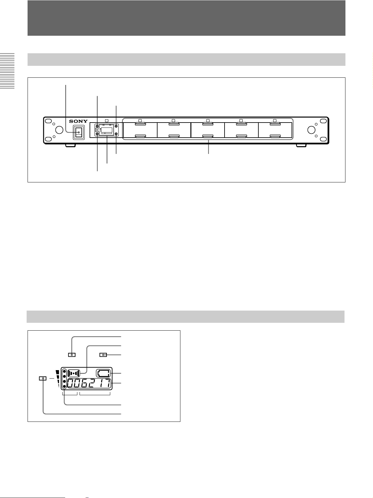
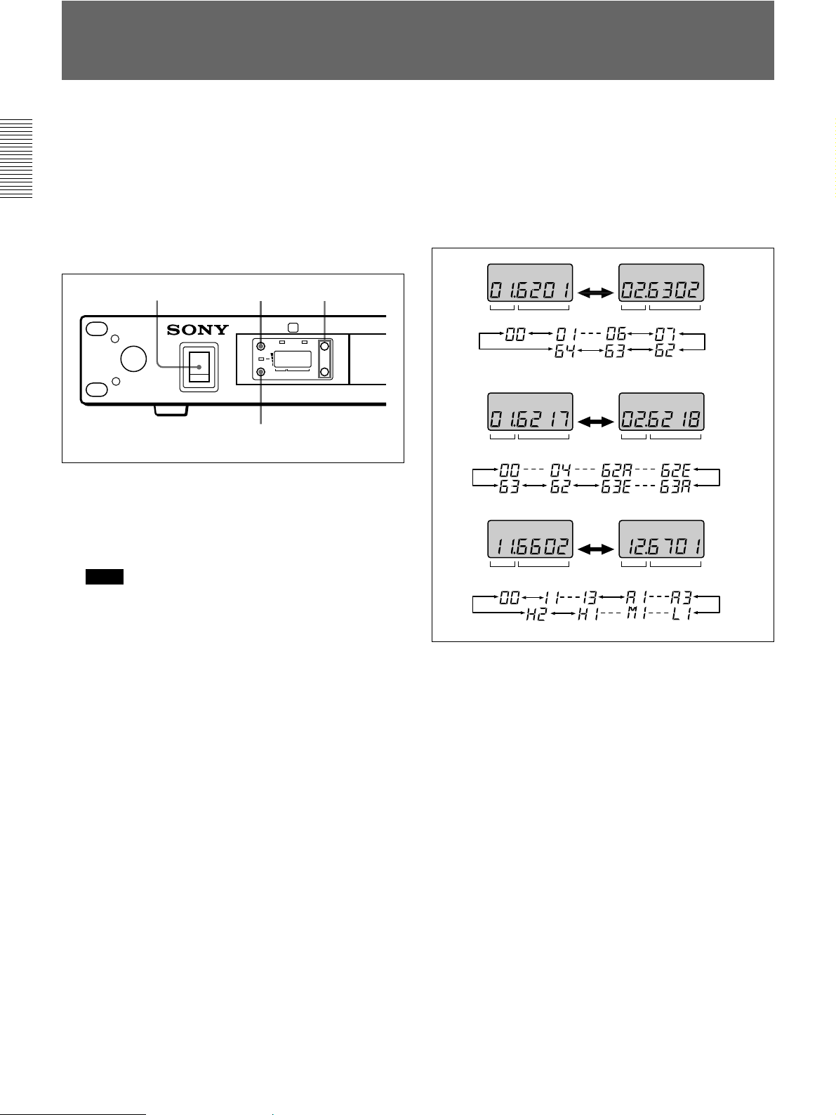
Front Panel
1 POWER switch
2 GP button
4 + button
1
GP
BATTAF
ON
OFF
POWER
RF
CH
3 CH button
+
–
GP CH
5 – button
6 Display
2 3 4 5 6
1 POWER switch
Turns the power on and off.
2 GP (group) button
To change the group, press the + or – button while
holding this button down.
3 CH (channel) button
To change the channel in a group, press the + or –
button while holding this button down.
4 + button
To go to a higher group or channel, press this button
while holding the GP or CH button.
Press this button changes the indication from GP/CH
to frequency.
7 Blank panels
5 – button
To go to a lower group or channel, press this button
while holding the GP or CH button.
6 Display
Displays the status of the tuner and the group and
channel assigned to the unit.
For details, see the following section “Display”.
7 Blank panels
Remove these panels to install optional WRU-806A/
WRU-806B UHF Synthesized Tuner Units.
Display
1 AF indicator
2 AF level indications
3 BATT indicator
BATTAF
RF
GP CH
1 AF (audio frequency) indicator
2 AF (audio frequency) level indications
The indicator lights and the indications appear when
the audio output level is higher than the reference
level.
4(GB)
4 BATT indication
5 GP/CH indication
6 RF level indications
7 RF indicator
3 BATT (battery) indicator
4 BATT (battery) indication
Indicate the condition of the wireless microphone
transmitter batteries. The indicator and indication
appear and start flashing about one hour before the
transmitter batteries go flat.
The time at which flashing begins will depend on the
type of battery used in the transmitter, and its
condition.
5 GP/CH (group/channel) indication
Shows the reception channel group and respective
channel number.
Pressing the + button changes this indication to the
frequency indication.
6 RF (radio frequency) level indications
7 RF (radio frequency) indicator
The indicator lights and the indications (dots) appear
when the antenna reception is optimal. Depending on
the RF input level, the number of dots changes.
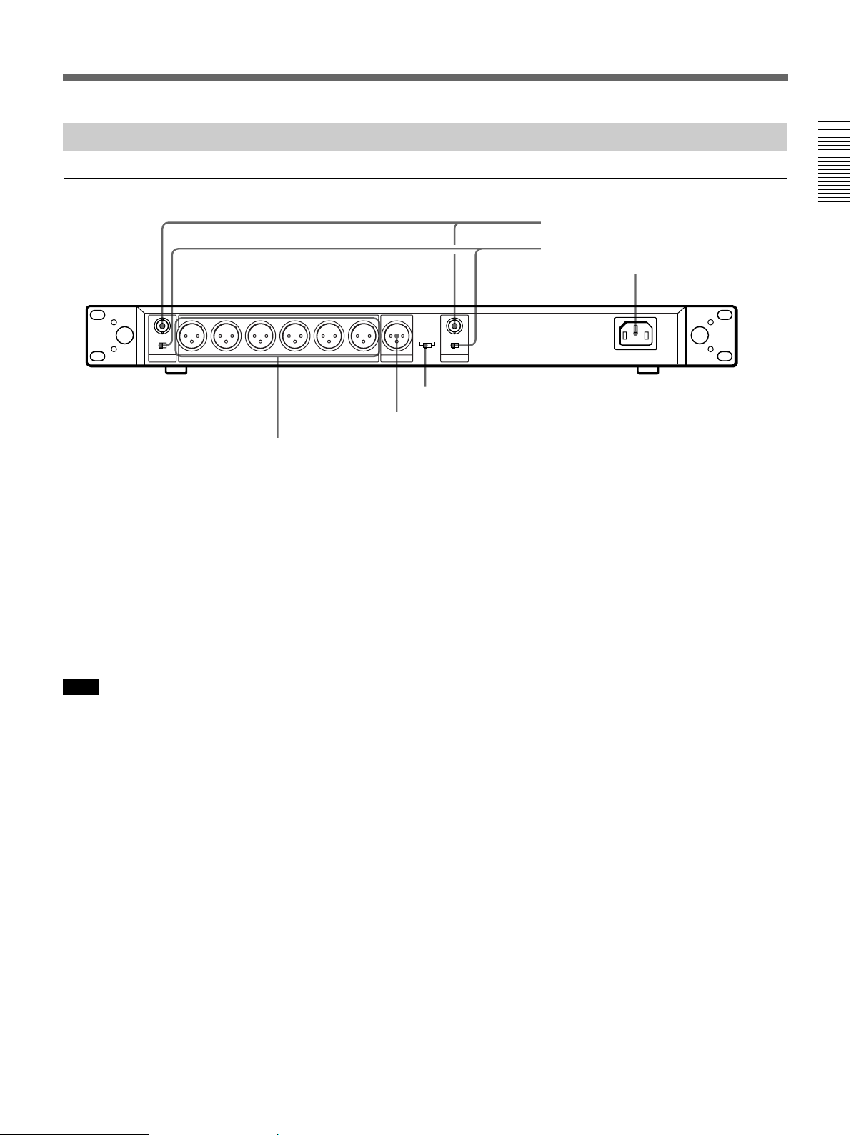
Rear Panel
IN(DC 9V OUT)
0610dB
ATT
ANTENNA B TUNER OUTPUT MIX OUTPUT
5 4 3 2 1
6 TUNER OUTPUT connectors
OUTPUT
LEVEL
LINE
MIC
IN(DC 9V OUT)
–20dBm
–58dBm
0 10dB
ATT
ANTENNA A
4 OUTPUT LEVEL switch
5 MIX OUTPUT connector
1 ANTENNA A, B IN/DC 9V OUT connectors
2 ANTENNA A, B ATT switches
3 AC IN connector
AC IN
⁄
1 ANTENNA A, B IN/DC 9V OUT (antenna A, B
input/DC power output) connectors (BNC type)
Connect the supplied antenna or an optional AN-820A
UHF Antenna. To connect two of these units, these
connectors are connected to the ANTENNA OUT
connectors of the WD-820A UHF Antenna Divider.
When the AN-820A is connected, 9 V DC power is
supplied to the antenna’s internal booster through these
connectors.
Note
Never short-circuit these connectors.
2 ANTENNA A, B ATT (attenuation) switches
Select the RF attenuation as 0 dB or 10 dB.
Usually set the switches to 0 dB. If noise generates or
sound discontinues due to interference, set the
switches to 10 dB.
It is recommended that you set the switches as follows
depending on the antennas connected to the
ANTENNA A, B IN/DC 9V OUT connectors.
Using the supplied antenna: 0 dB
Using an optional AN-820A UHF Antenna (with a
WD-820A Antenna Divider): 10 dB when the coaxial
cable (5D-2V, RG-212/U or equivalent) connecting the
antennas and tuner is 30 m (100 feet) or less, or 0 dB
when the cable is over 30 m (100 feet)
3 AC IN connector
Connects to an AC power source with the supplied AC
power cord.
4 OUTPUT LEVEL switch
Selects the mixed output level and tuner output level as
–20 dBm or –58 dBm.
Set this switch according to the input level of the
equipment connected to the unit.
5 MIX OUTPUT connector (XLR type)
Supplies mixed audio signals of six tuner units. You
can connect this to the audio input connector of a
mixer, amplifier or similar equipment.
6 TUNER OUTPUT (tuner sound output) (XLR
type)
Each connector supplies the audio signal from the
corresponding tuner unit. You can connect this to the
audio input connector of a mixer, amplifier, or similar
equipment.
5(GB)
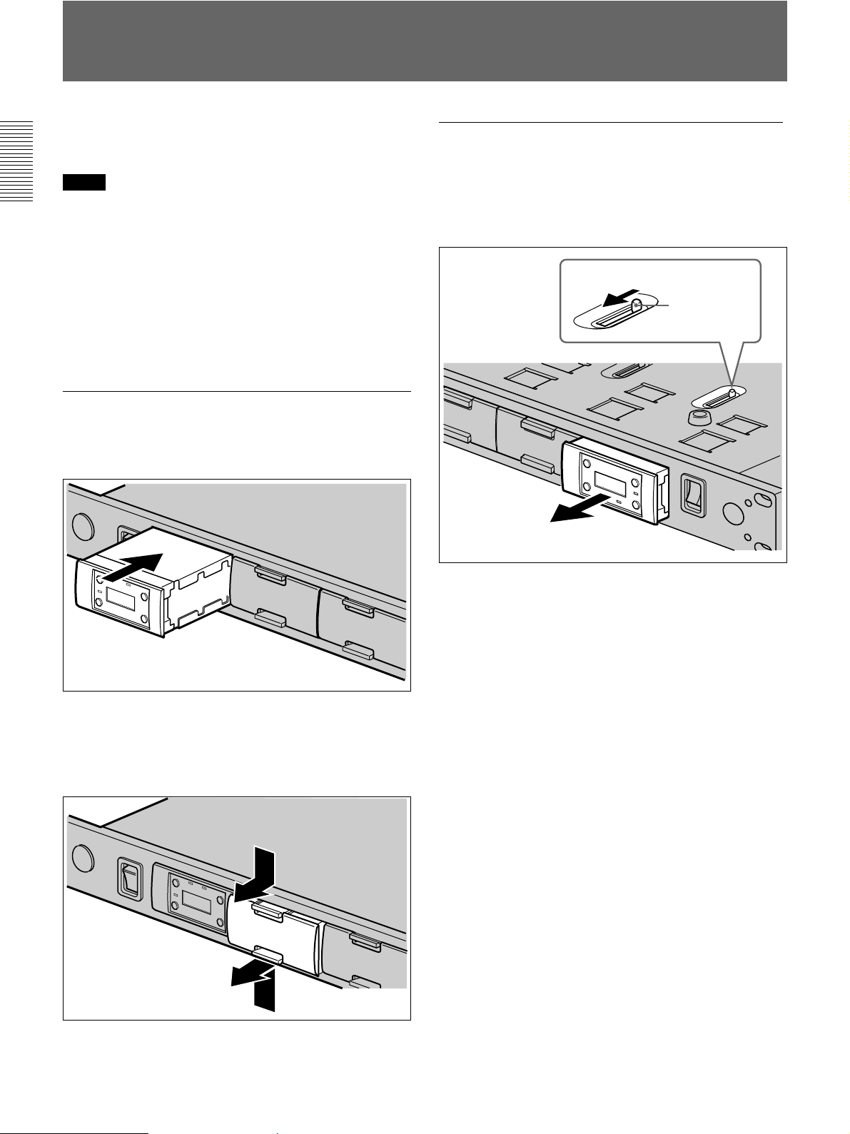
Installing a WRU-806A/WRU-806B Tuner Unit
Up to six WRU-806A/WRU-806B UHF Synthesized
Tuner Units can be installed.
Notes
•Be sure to power this unit off before installing the
WRU-806A/WRU-806B.
•The buttons and display on the front panel of the
WRU-806A/WRU-806B may be damaged if they are
gripped too strongly. Always hold the WRU-806A/
WRU-806B by the side.
•Do not touch the connectors on the rear panel of the
WRU-806A/WRU-806B.
•Be careful of static electricity.
Installing a WRU-806A/WRU-806B
1 Hold the WRU-806A/WRU-806B by the side and
insert into the slot. Push in until you hear a click.
Removing a WRU-806A/WRU-806B
On the bottom panel of the tuner, locate the lever
corresponding to the slot where the WRU-806A/
WRU-806B is installed and pull the lever forward.
The WRU-806A/WRU-806B is ejected from the slot.
Lever
Bottom Panel
2 To install two or more units, detach the necessary
number of blank panels by pushing in the top and
bottom tabs of each panel and pulling the panel
out. Then do step 1 for each unit.
6(GB)
Connections
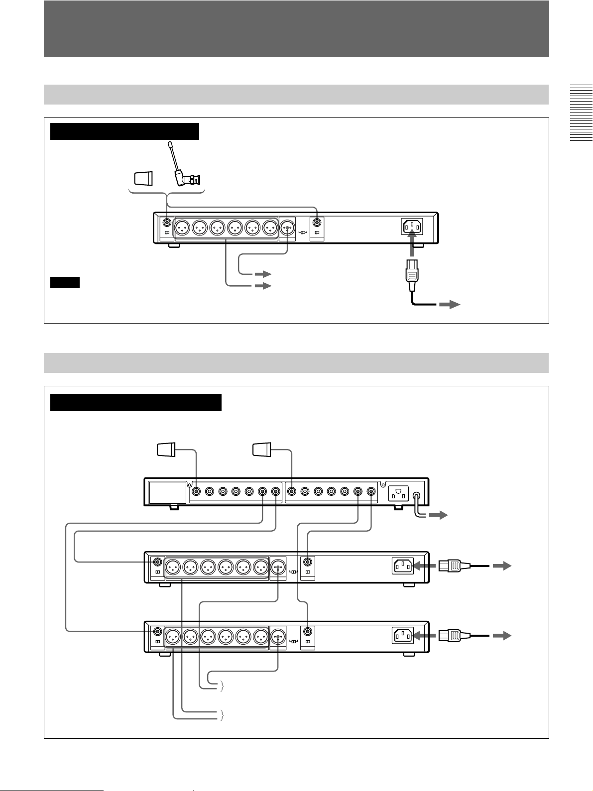
Basic Connections
When using 1 to 6 channels
AN-820A UHF
Antenna
ANTENNA B IN ANTENNA A IN
or
TUNER OUTPUT
Notes
•Make sure to use a pair of antennas.
Antenna
(supplied)
A
Connect output A or B
to a mixer or an
B
amplifier.
•Make the antenna tips point upward.
Connection for Multichannel Operation
When using 7 channels or more
AN-820A UHF Antenna
MIX OUTPUT
Power cord
(supplied)
MB-806A
AC IN
To AC power source
WD-820A UHF
Antenna Divider
ANTENNA B IN
TUNER OUTPUT
ANTENNA B IN
TUNER OUTPUT
MB-806A
ANTENNA B IN
MIX OUTPUT
MIX OUTPUT
A
Connect output A or B
to a mixer or an amplifier.
B
ANTENNA A IN
ANTENNA A INMB-806A
ANTENNA A IN
To AC power
source
Power cord
(supplied)
Power cord
(supplied)
To AC power
source
To AC power
source
7(GB)
Channel Setting
Take the following precautions to prevent interference
and noise.
•If there is a TV broadcasting station nearby, to avoid
possible interference from its broadcasting, do not
use that station’s channel.
•When simultaneously using two or more tuners,
always set the tuners to different channels within the
same group (other than group 00).
1
ON
OFF
POWER
2
GP
RF
CH
1
GP CH
2,3,4
BATTAF
+
–
3,4
1 Turn the POWER switch on.
The model version number such as “CE62” or
“CE67” appears on the display, and then the
current tuner status is displayed.
2 Press and hold down the GP button, and press the
+ or – button to select a group.
Each time you press the + or – button, the GP
indication changes as shown in the following
figure. To change the indication continuously,
press and hold down the + or – button.
–+
GP CH GP CH
Display example of WRU-806B (CE62 model)
–+
GP CH GP CH
Display example of WRU-806A (CE62 model)
–+
Note
Turn the POWER switch on after reducing the
volume of equipment connected to the TUNER
OUTPUT connector. Otherwise, noise will be
heard when the power is turned on.
GP CH GP CH
Display example of WRU-806A (AU66 model)
The CH indication shows the lowest frequency
channel of the selected group. For group 00,
however, the channel selected last is displayed.
Releasing the buttons automatically cancels the
group and channel selection mode, and the
currently displayed group is selected.
See “Wireless Channel Lists” on page L-1 (for WRU806A users) or refer to “Wireless Microphone System
Frequency List” supplied with the WRU-806B (for
WRU-806B users).
8(GB)
3 Press and hold down the CH button, and press the
+ or – button in 3 seconds to select a channel.
Similar to step 2, each time you press the + or –
button, the CH indication changes in the order
shown in the group and reception channel list.
See “Wireless Channel Lists” on page L-1 (for WRU806A users) or refer to “Wireless Microphone System
Frequency List” supplied with the WRU-806B (for
WRU-806B users).
If you press the + button when the last channel of
the selected group is displayed, the first channel of
the group will be displayed.
–+
Automatic Search and Setting of Available Channels
When you use the MB-806A Base Unit in a multichannel operation system, you can assign available
channels to all tuner units by operating the first tuner
unit only.
Note
Auto channel assignment function is available only
when the tuner base unit holds the tuner units in the
same TV channels.
1 Power off all wireless microphones and
transmitters.
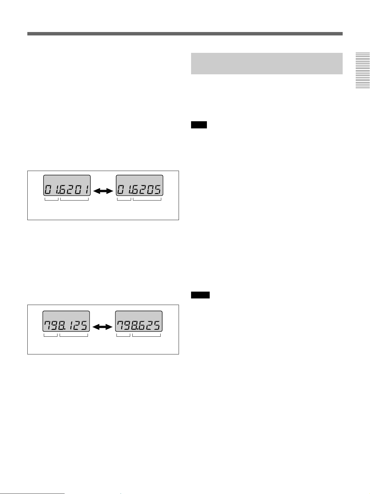
2 On the first tuner unit, select the group to be used.
GP CH GP CH
Display example of WRU-806B (CE62 model)
Selecting the reception channel by frequency
Press the + button.
This changes the GP/CH indication to a frequency
indication.
To change a frequency, press the + or – button
while keeping the CH button pressed. (A higher or
lower frequency will be displayed.)
Press the + button again to change the frequency
indication to a GP/CH indication.
–+
GP CH GP CH
Display example of WRU-806B (CE62 model)
4 If the desired channel or frequency is displayed,
release the CH button and + or – button.
3 Press the CH button on the first tuner unit and hold
it down for 3 seconds.
The first tuner unit searches for available channels
in the selected group, and available channels in the
group are so assigned to all tuner units
automatically that two or more tuner units may not
use the same channel.
After automatic setting, you can adjust the groups
and channels of individual tuner units.
Notes
•Do not use group 00.
•If no channels are available, “NO CH” is displayed
and channel setting is aborted.
The selected channel is set.
To store the selected group and channel
Leave the indication unchanged for 1 second.
The group and channel set in the procedure explained
above are stored in memory.
9(GB)

When using two MB-806A Base Units
When you use two base units, proceed as follows to
ensure that the two tuner units do not use the same
channel settings.
1 Follow the procedure explained above to set the
group and channel of the first base unit.
2 Power on the wireless microphones or transmitters
after adjusting them to the channels of each tuner
unit.
Note
If the microphones or transmitters are not powered
on, the two tuner units may use the same channel
twice.
3 On the first tuner unit of the second base unit, set
the same group as selected on the first base unit.
4 Press the CH button of the first tuner unit on the
second base unit and hold it down for 3 seconds.
Available channels in the same group (channels
not used by the first base unit) are automatically
set on the first tuner unit and the other tuner units
on the second base unit.
Note
If automatic channel setting dose not function well for
the second base unit (due to poor reception), set
channels manually for the second base unit.
10(GB)
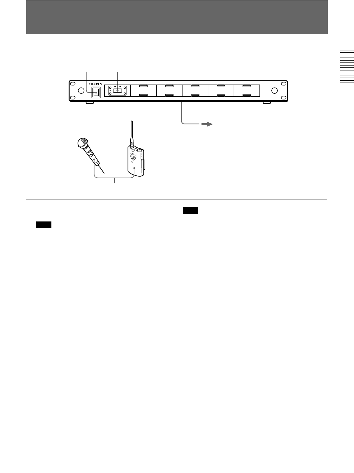
Operation
UHF synthesized
wireless
microphone
1 2
3
+
–
UHF synthesized
transmitter
Connect the output signals to a mixer or an
amplifier (see page 7).
1 Turn the POWER switch on.
Note
Turn the POWER switch on after reducing the
volume of the equipment connected to the TUNER
OUTPUT connector. Otherwise, noise will be
heard when the POWER switch is turned on.
2 Set the reception channel.
For details on setting the channels on the tuner, see
“Channel Setting” on page 8.
3 Turn on the wireless microphone or transmitter.
Use the wireless microphone or transmitter to
which the same channel is assigned as to the tuner.
If noise is heard
Depending on the environment where the system is
installed, outside noise or radio wave may disrupt the
transmission of certain channels.
To select a channel under this circumstance, turn off
the wireless microphone and transmitter. Then select a
channel at which the RF indicator is off. (A channel
free from noise or radio wave interference is selected.)
Set the same channel on the microphone or transmitter.
Note
To eliminate interference or noise, please note the
following.
•Do not use two or more wireless microphones or
transmitters whose wireless channels are the same.
•Separate the reception antennas and the transmitter by
more than 3 meters.
•The number of wireless microphone channels
actually usable in a multi-channel system may be
smaller than the normal capacity of that system if
there is interference from TV broadcasting or other
RF signals.
•When operating two or more UHF wireless
microphone systems using the same wireless channel
in the same group, ensure that the systems are at least
1)
100 m
apart as far as they are installed within sight
of each other.
..........................................................................................................................................................................................................
1) The distance depends on the operating environment and
conditions.
11(GB)

Muting Functions
This tuner has the following three muting functions,
which work in combination.
(1) Muting by RF input level
As sufficient S/N for the audio output may not be
obtained if no RF signal is received or the RF input
level is low, the audio output can be muted when the
RF input level falls below the muting level.
(2) Tone squelch
The audio output is obtained only when the tuner
receives an RF signal which includes a specified tone
signal. The audio output is muted to eliminate noise
which may be heard when the transmitter is turned on/
off or the tuner receives an interference RF signal.
(3) Noise squelch
The audio output is muted to eliminate noise which
may be heard when there is such excessive
interference RF signal that the tone squelch does not
work.
To turn off the muting functions
While holding down the GP and CH buttons, turn the
POWER switch to ON. All indications momentarily
appear, then go off. “OFF” is then displayed. This
procedure cancels all three muting functions at the
same time.
To turn on the muting functions
Turn the POWER switch to OFF, then to ON again.
The three muting functions are activated at the same
time.
12(GB)
 Loading...