

Sony MAV-777 Operation Manual
REMOTE
R1
PORT SELECT
R2/P3R3/
P2
P1
INPUT
HD SDI
AES/EBU
CH1
CH1
PRESET
AUDIO INPUT / MONITOR SELECT
CH2 CH3 CH4
MONITOR
L
R
METER
PANEL
REMOTE
MENU
LOCAL
CONTROL
PANEL
SETUP BANK
TOTAL /
REMAIN
PROCESS
CONTROL
Y/
MASTER
PB
PR
SET UP
PHONES
123
SYSTEM HDD
HELP
FULL /
FINE
TC/UB TC TYPE
MENU
10
SET
0
CH2
PRESET
CH3
PRESET
CH4
PRESET
VIDEO/MENU
PRESET
9P
50P
REMOTE
CONTROL PANEL
PANEL SELECT CHARACTER
REAR FRONT
1 2 3
NONE OFF ON80TH
SETUP
SELECT
IN OUT
PB EE PB
L1
L2
L3
L4
L5
L6
L7
L8
L9
L10
L11
B1 B2 B3 B4 B5 B6 B7
MODE SHIFT
IN
DMC EDIT
PREVIEW
AUTO EDIT
REVIEW
MEMORY
DELETE
OUT
TRIM
AUDIO
ENTRY
HOLD RESET TC/UB TC TYPE
1
2
EXT
R1
R2/
P3
PORT SELECT
P1
SHUTTLE
MULTI
CONTROL
PLAYER
PREROLL EDIT
REW PLAY F. FWD STOP
REC
RECORDER
JOG VAR
F
O
R
W
A
R
D
R3/
P2
MULTI ACCESS VIDEO DISK RECORDER
MAV-777 (Ver. 2.32)
Volume I Settings, Basic Operations by Modes
OPERATION MANUAL
[English]
1st Edition (Revised 1)
Serial No. 10001 and Higher

To prevent fire or shock hazard, do not
expose the unit to rain or moisture.
To avoid electrical shock, do not open the
cabinet. Refer servicing to qualified
personnel only.
Afin d’éviter tout risque d’incendie ou
d’électrocution, ne pas exposer cet
appareil à la pluie ou à l’humidité.
Afin d’écarter tout risque d’électrocution,
garder le coffret fermé. Ne confier
l’entretien de l’appareil qu’à un personnel
qualifié.
Um Feuergefahr und die Gefahr eines
elektrischen Schlages zu vermeiden, darf
das Gerät weder Regen noch Feuchtigkeit
ausgesetzt werden.
Um einen elektrischen Schlag zu
vermeiden, darf das Gehäuse nicht
geöffnet werden. Üb erlassen Sie
Wartungsarbeiten stets nur qualifizierte m
Fachpersonal.
This symbol is intended to alert the user to the presence
of important operating and maintenance (servicing)
instructions in the literature accompanying the appliance.
WARNING:THIS WARNING IS APPLICABLE FOR USA
ONLY.
If used in USA, use the UL LISTED power cord specified below .
DO NOT USE ANY OTHER POWER CORD.
Plug Cap Parallel blade with ground pin
(NEMA 5-15P Conf ig uration)
Cord Type SJT, three 16 or 18 AWG wires
Length Less than 2.5 m (8 ft. 3 in.)
Rating Minimum 10 A, 125 V
WARNING:Using this unit at a voltage other than 120 V may
require the use of a different line cord or
attachment plug, or both. To reduce the risk of fire
or electric shock, refer servicing to qualified
service personnel.
WARNING:THIS WARNING IS APPLICABLE FOR OTHER
COUNTRIES.
1. Use the approved power cord (3-core mains lead)/ap pliance
connector/plug with earthing-contacts that conforms to the
safety regulations of each country if applicable.
2. Use the power cord (3-core mains lead)/appliance connector/
plug conformi ng to the proper ra tings (voltage, ampere).
If you have questions on the use of the above power cord/
appliance connector/plug, please consult a qualified service
personnel.
AVERTISSEMENT: CET AVERTISSEMENT EST
APPLICABLE AUX AUTRES PAYS.
1. Utiliser un cordon d’alimentation approuvé (conducteur
d’alimentation 3 âmes)/connecteur d’appareil/prise avec
contacts de mise à la terre conforme aux règles de sécurité de
chaque pays si applicable.
2. Utiliser un cordon d’alimentation approuvé (conducteur
d’alimentation 3 âmes)/connecteur d’appareil/prise conforme
aux valeurs nominales (tension, ampérage) correctes.
S’adresser à un person nel de serv ice qua lifié pour tout e questi on
concernant l’emploi du cordon d’alimentation/connecteur
d’appareil/prise ci-dessus.
WARNUNG: DIESE WARNUNG GILT FÜR ANDERE
LÄNDER.
1. Verwenden Sie Netzkabel (dreiadrig), Geräteanschlüsse und
Netzkabelstecker mit Masseleitung, die den
Sicherheitsrichtlinien des jeweiligen Landes entspricht.
2. Verwenden Sie Netzkabel (dreiadrig), Geräteanschlüsse und
Netzkabelstecker mit Masseleitung, die den vor Ort
herrschenden Spannungsanforderungen (Spannung,
Stromstärke) entsprechen.
Bei Fragen über die Eignung und Sicherheit von Netzkabeln
(dreiadrig), Geräteanschlüssen und Netzkabelsteckern wenden
Sie sich bitte an einen qualifizierten Elektrotechniker.
WARNING
THIS APPARATUS MUST BE EARTHED.
AVERTISSEMENT
CET APPAREIL DOIT ÊTR E RELIÉ À LA TERRE.
WARNUNG
DIESES GERÄT MUSS GEERDET WERDEN.
WARNING
AVERTISSEMENT
WARNUNG

For the customers in the USA
This equipment has been tested and found to comply with the
limits for a Class A digital device, pursuant to Part 15 of the FCC
Rules. These limits are designed to provide reasonable
protection against harmful interference when the equipment is
operated in a commercial environment. This equipment
generates, uses, and can radiate radio frequency energy and, if
not installed and used in accordance with the instruction manual,
may cause harmful interference to radio communications.
Operation of this equipment in a residential area is likely to
cause harmful interference in which case the user will be
required to correct the interference at his own expense.
You are cautioned that any changes or modifications not
expressly approved in this manual could void your authority to
operate this equipment.
The shielded interface cable recommended in this manual must
be used with this equipment in order to comply with the limits
for a digital device pursuant to Subpart B of Part 15 of FCC
Rules.
For the customers in Europe
This product with the CE marking complies with both the EMC
Directive (89/336/EEC) and the Low Voltage Directive (73/23/
EEC) issued by the Commission of the European Community.
Compliance with these directives implies conformity to the
following European standards:
• EN60950: Product Safety
• EN551 03-1: Electromagnetic Interference (Emission)
• EN5510 3-2 : Electromagnetic Susceptibility (Immunity)
This product is intended for use in the following
Electromagnetic Enviroment(s):
E1 (residential), E2 (commercial and light industrial), E3 (urban
outdoors) and E4 (controlled EMC environment, ex. TV studio).
Pour les clients europ éens
Ce produit portant la marque CE est conforme à la fois à la
Directive sur la compatibilité électromagnétique (EMC) (89/
336/CEE) et à la Directive sur les basses tensions (73/23/CEE)
émises par la Commission de la Communauté européenne.
La conformité à ces directives implique la conformité aux
normes européennes suivantes:
• EN60950: Sécurité des produits
• EN5 5103-1: Interférences électromagnétiq ues (émission)
• EN5510 3-2 : Sensib ilité électromagnétique (immunité)
Ce produit est prévu pour être utilisé dans les environnements
électromagnétiques suivants:
E1 (résidentiel), E2 (commercial et industrie légère), E3 (urbain
extérieur) et E4 (environnement EMC contrôlé, ex. studio de
télévision).
Für Kunden in Europa
Dieses Produkt besitzt die CE-Kennzeichnung und erfüllt
sowohl die EMV-Direktive (89/336/EEC) als auch die Direktive
Niederspannung (73/23/EEC) der EG-Kommission.
Die Erfüllung dieser Direktiven bedeutet Konformität für die
folgenden Europäischen Normen:
• EN60950: Produktsicherheit
• EN551 03-1: Elektromagnetische Interferenz (Emission)
• EN55103-2: Elektromagnetische Empfindlichkeit
(Immunität)
Dieses Produkt ist für den Einsatz unter folgenden
elektromagnetischen Bedingungen ausgelegt:
E1 (Wohnbereich), E2 (kommerzieller und in beschränktem
Maße industrieller Bereich), E3 (Stadtbereich im Freien) und E4
(kontrollierter EMV-Bereich, z.B. Fernsehstudio).
Voor de Klanten in Nederland
Dit apparaat bevat een vast ingebouwde batterij die niet
vervangen hoeft te worden tijdens de levensduur van het
apparaat.
Raadpleeg uw leverancier indien de batterij toch vervangen moet
worden. De batterij mag alleen vervangen worden door
vakbekwaam servicepersoneel.
Gooi de batterij niet weg maar lever deze in als klein chemisch
afval (KCA).
Lever het apparaat aan het einde van de levensduur in voor
recycling, de batterij zal dan op correcte wijze verwerkt worden.
Für Kunden in Deutschland
Die in diesem Produkt verwendete Speicherbatterie muß
während der Lebensdauer des Produkts nicht ausgetauscht
werden.
W enn die Batterie nach langer oder intensiver Nutzung erschöpft
ist und entsorgt werden muß, wenden Sie sich bitte an den
Händler, bei dem Sie das Produkt erworben haben. Um einen
möglichen Kurzschluß oder elektrischen Schlag zu vermeiden,
darf die Batterie nur durch qualifiziertes Kundendienstpersonal
herausgenommen und ausgetauscht werden.
Entsorgen Sie die Batterie als Sondermüll. Entsorgen Sie sie
nicht im normalen Müll.

4 (E) Table of Contents
Table of Cont en ts
Chapter 1 Overview
1-1 MAV-777 Overview..........................................1-1
1-2 Features.............................................................1-1
1-3 Changes from Ver. 1.00....................................1-3
1-3-1 Changes from Ver. 1.00 to Ver. 2.32..........1-3
1-4 Optional Accessories........................................1-3
Chapter 2
Names and Functions of
Parts
2-1 Front Panel.......................................................2-1
2-1-1 Meter Panel................................................2-2
2-1-2 Control Panel.............................................2-6
2-2 System Setup Panel..........................................2-7
2-3 Connector Panel...............................................2-9
Chapter 3 Preparations
3-1 Overview of Operation Modes........................3-1
3-2 Connecting External Devices ..........................3-7
3-2-1 Connections with the Panel Mode.............3-7
3-2-2 Connections with the DTR + Panel Mode.3-8
3-2-3 Connections with the DTR + DTR Mode .3-9
3-2-4 BVE Mode Connections..........................3-10
3-3 External Synchronization of Output Video
Signals ...........................................................3-11
3-4 Setup................................................................3-12
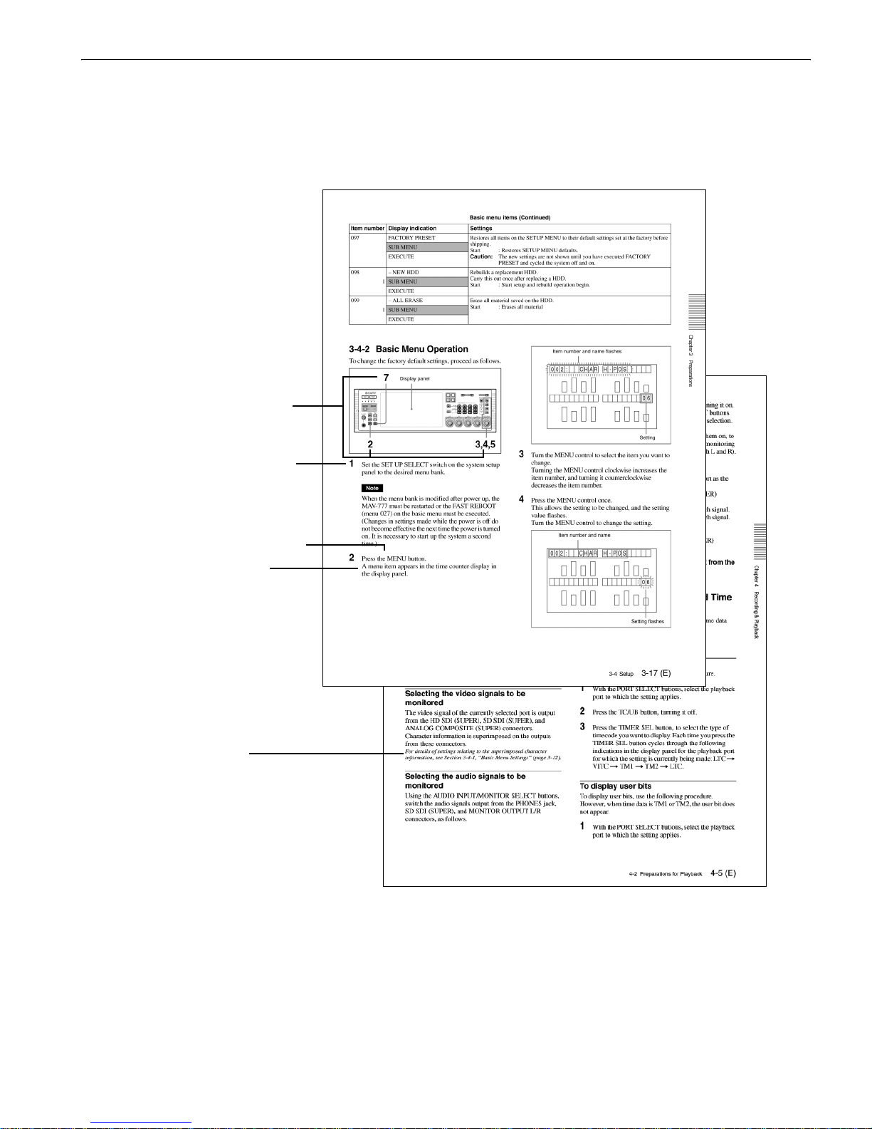
3-4-1 Basic Menu Settings ................................3-12
3-4-2 Basic Menu Operation.............................3-17
3-4-3 Contents of the Expansion Menu ............3-19
3-4-4 Expansion Menu Operation.....................3-33
3-4-5 System Time Settings..............................3-33
3-5 Superimposed Character Information.........3-34
Chapter 4 Recording & Playback
4-1 Preparations for Recording.............................4-1
4-1-1 Switch Settings..........................................4-1
4-1-2 Selecting the Recording Port
to be Controlled.......................................4-2
4-1-3 Selecting the Audio Signals ......................4-2
4-1-4 Selecting the Video and Audio Signals
to be Monitored........................................4-2
4-1-5 Adjusting Recording Levels......................4-3
4-1-6 Selecting the External Device Used for
Controlling Recording Operations...........4-3
4-2 Preparations for Playback...............................4-4
4-2-1 Switch Settings..........................................4-4
4-2-2 Selecting the Playback Port
to be Controlled........................................4-5
4-2-3 Selecting the Video and Audio Signals
to be Monitored........................................4-5
4-2-4 Selecting the Displayed Time Data............4-5
4-2-5 Adjusting Playback Audio Levels..............4-6
4-2-6 Selecting the External Device Used
for Controlling Playback Operations .......4-6
4-2-7 Remotely Controlling the Video Processor4-6
Chapter 5
Basic Functions of Each
Mode
5-1 Changing the Operation Mode........................5-1
5-2 Basic Operation with Panel Mode ..................5-1
5-2-1 Recording Operation..................................5-1
5-2-2 Playback Operation....................................5-1
5-2-3 EE Signal Selection ...................................5-2
5-3 Basic Operations with DTR+Panel and
DTR+DTR Modes...........................................5-3
5-3-1 Initia l Setup for DTR+Panel
and DTR+DTR Modes.............................5-3
5-3-2 Basic Operations in DTR+Panel
and DTR+DTR Modes.............................5-3
5-4 Basic Operations in BVE Mode......................5-5
5-4-1 Port Configuration .....................................5-5
5-4-2 Basic Operation of the RP Port..................5-5
5-4-3 Basic Operation of the R2 Port..................5-6
5-4-4 Basic Operation of the P2 and P3 Ports.....5-7
5-4-5 New File Names.........................................5-8
5-4-6 Monitoring the RP Port..............................5-8
5-4-7 Pre-roll Ti me..............................................5-8
5-4-8 File Backup Function.................................5-8
5-4-9 Editing-Related Error Messages................5-8
Appendixes
Effect Pattern List.................................................A-1
Error Messages.....................................................A-2
Specifications.........................................................A-5

About This Operation Manual 5 (E)
About This Operation Manual
This section describes the organization and use of this
manual in using the Sony MAV-777 Multiaccess Video
Disk Recorder . This unit is a hard disk recorder, b ut has the
operability of a VTR, allowing easy understanding and
operati on by those experienced at usi ng VTRs. Read this
section to understan d h ow the manual is put together, and
determine which sections you need to read, according to
your degree of experience with a VTR.
The operation manual of the MAV-777 is divided into two
manuals as outlined below.
Volume I: Settings, Basic Operations by Modes
(This manual)
Volume I describes the various functions of th e MAV -777,
the procedures to connect external control devices, and
menu settings. Refer to this manual when you want to
build an editing system or modify an existing editing
system.
Volume II: Editin g O pe rati on s from the Control
Panel
Volume II describes how to use the MAV-777 control
panel. Refer to this manual when you want to record,
playback, or edit with th e control panel. Also refer to it
when you want to edit using effects such as wipe and
dissolve, perform DMC editing, A/V split editing, and so
forth.
Purpose and intended audience for this
manual
This operation manual describes th e parts and functions of
the MAV-777, preparations for operation, basic
operations, and other essential information required for
using the unit.
This unit is intended for use principally by operators in
broadcasting stations and production houses. It therefore
assumes that the reader h as a gener al underst anding of the
operation of VTRs and other broadcast equipment.
Readers well-acquainted with the operation of VTRs and
hard disk recorders, after reading Chapter 2 “Names and
Functions of Parts”, should be able to understand the
operation of the unit, with reference to other sections as
required.
However, regardless of experience level, you are
recommended to read Chapter 1 “Overview” to get a
grasp of the many features and functions of the unit.
For first-time users of a VTR or hard disk recorder, or
those with limited experience, a thorough reading of this
manual is recommended.
Organization of this manual
This manual is divided into chapters as follows.
Chapter 1 Overview
This gives an overview of the features of the unit.
Chapter 2 Names an d Fun ct ions of Parts
This lists the parts of the unit by function, with summaries
of their operation.
Chapter 3 Preparations
Gives an overview the four operation modes of the MAV777 (Panel, DTR+Panel, DTR +DTR, BVE), and describes
how external devices are connected for each operation
mode. The initial settings for items in the MA V-777 Basic
menu and Expansion menu are also described.
Chapter 4 Recording & Playback
This chapter describes the preparations and settings for
recording and playback.
Chapter 5 Basic Functions of Each Mode
Describes the basic functions of t he four operat ing modes
of the MAV-777, described in Chapter 3.
Appendixes
• Error Messages
This appendix lists MAV-777 errors and warnings that
appear on the front display panel.
• S pecifications
This provides the basic physical specifications, and
specifications of the audio and video systems of the unit.
6 (E) About This Operation Manual
Using this manual
Description s of operating procedures
The numerals attached to buttons and switches in the
illustrations refer to corresponding step numbers in the
operating procedure. Additionally, affected switches and
indicators which should be checked are indicated.
The first time a technical term appears it is defined in a
footnote. Where required, a cross-reference (in italics)
shows the page in this manual or in another manual where
related information may be found.
Numbers on switches etc.
refer to steps in procedure
Step number in procedure
Results of a step and
related information
Description of step operation
Cross-reference
Example of procedure description

About This Operation Manual 7 (E)
Related manuals
The following related manuals are also available.
• Operation Manual
Volume II Editing Operations from the Control
Panel (supplied)
This describes the various editing operations possible
with the MAV-777 control panel.
• Installation Manual (supplied)
This describes the installa tion procedure for this unit.
• Maintenance Manual (Option)
This lists basic maintenance procedures, associated
accessories, electrical adjustment procedures, and how
to replace the unit’s HDDs.

Chapter 1 Overview
1-1 MAV-777 Overview / 1-2 Features 1-1 (E)
Chapter 1 Overview
1-1 MAV-777 Overview
The MAV-777 is a multi-access video disk recorder
capable of recording compressed video images based on
the HDCAM compression format. Close compatibility
with existing VTR-based editing systems is preserved by
a VTR-like interface, with the added benefits of highspeed search functions and nonlinear editing made
possible by hard disk recording.
The internal hard disk drive (henceforth, HDD), provides
a maximum recording time of 8 hours (MAV-777/08).
Input/output can be configured as 1 input/1 output
(standard), 2 input/ 2 output , 1 input/ 3 outpu t, or 3 input /1
output (with the appropriate optional board). The signal
type is HD SDI for video input/output, and HD SDI and
AES/EBU are available for audio input/output.
It also provides editing effects such as dissolve and wipe.
1-2 Features
Multi-access, Multi-operation
(Simultaneous recording/playback
operations possible while recording)
One of the advantages of a hard disk recorder (such as the
MAV-777) over a conventional HD VTR is the ability to
simultaneously access, edit, and output material (stored as
files) that is being recorded. The MAV-777 has one input
and one output port. In 1 input/1 output configuration,
each port can record or playback one video channel and
four audio channels. When using optional boards, it is
possible to expand each port to 2 input/2 output (with
BKMA-720/BKMA-730), 3 input/1 output (with two
BKMA-720), or 1 input/3 output (with two BKMA-730)
input/output port configurations. An external editor or
control panel can be used to perform multiple editing/
output operations simultaneously.
Flexible I/O Configuration Possible
Various I/O options are set according to the external
equipment that is connected and the operating
environment . The input and o utput conf igurations fo r this
device in the standard setup and when various optional
boards are installed are shown below.
For details on the basic options, refer to Section 1-4, “Optional
Accessories” (page 1-3) .
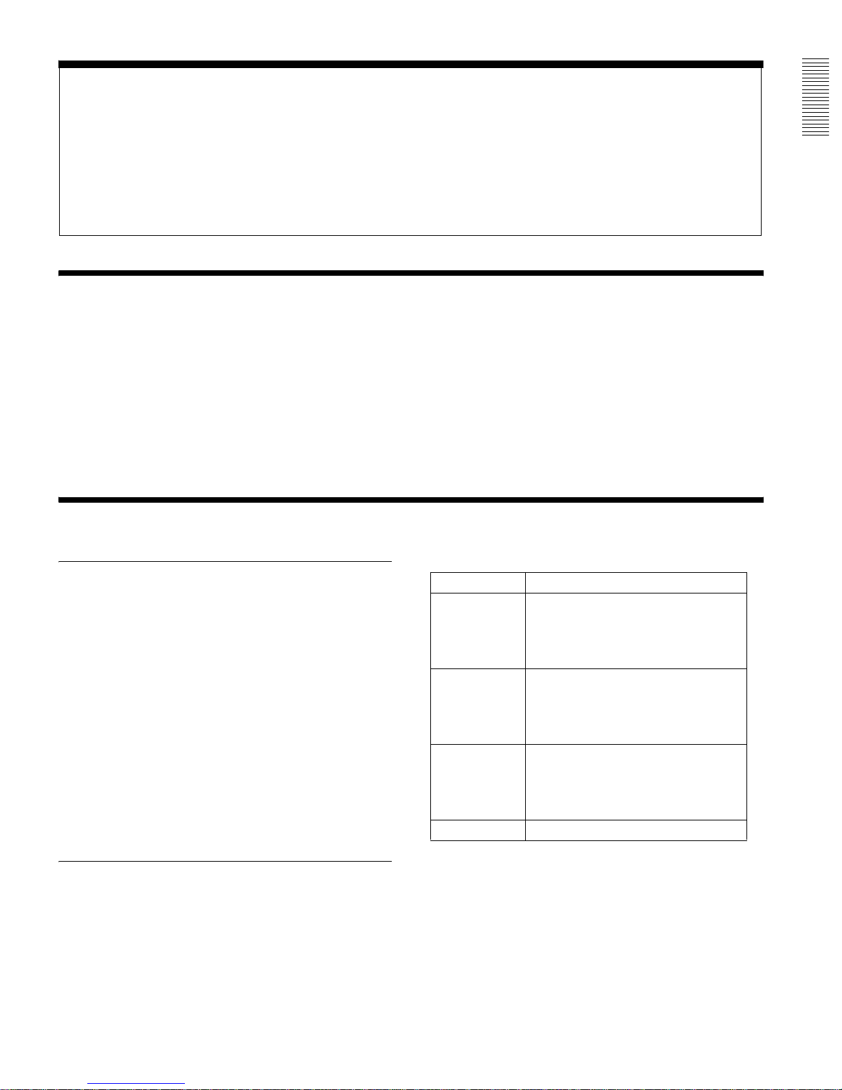
I/O Signals Standard/With optional boards
HD SDI video/
audio
Standard: 1 input/1 output
With optional boards:
2 input/2 output ( w ith BKMA-720/730);
3 input/1 output (with two BKMA-720);
1 input/3 output (with two BKMA-730)
SDI video/audio
(D CONV SDI
OUT)
Standard: 2 outputs
With optional boards:
4 outputs (with BKM A -720/730);
4 outputs (with two BKMA-720);
4 outputs (with two BKMA-730)
AES/EBU digital
audio
Standard: 1 input/1 output
With optional boards:
2 input/2 output ( w ith BKMA-720/730);
3 input/1 output (with two BKMA-720);
1 input/3 output (with two BKMA-730)
Time codes Standard

Chapter 1 Overview
1-2 (E) 1-2 Features
HDCAM format
The MAV -777 records video in HDCAM format , enabling
high-performance HD digital r ecording and playback. The
recording bit rate is 144 Mbps. The maximum recording
time depends on the H DD c apacity, as shown in the
following table.
Down convert function
The MAV-777 comes standard with an HD to SD down
converter. This makes it possible to output downconverted SD SDI (Super) signals to every input/output
ports.
Multifunction control panel
The upper panel of the MAV-777 (meter panel) enables
basic operations and editing. A standard multifunction
control panel (lower panel) with a layout and interface
similar to those of conventional HD VTRs allows smooth
nonlinear editing enriches the functionality of the MAV-
777. Further, the time difference function, the
simultaneous playback of tw o materia l (Dual Play mode) ,
A/V data transfer, and other high-level functions can be
simply performed from this control panel.
High grade AES/EBU digital audio as
standard equipment
This unit provides four independent 20-bit AES/EBU
digital audio signals on each HD SDI input/output port.
Further, you can record video signals and asynchronous
AES/EBU digital audio signals.
Ability to record asynchronous signa ls
By setting the standard signals of each recording port as
input signals, input signa ls that are a synchronous wi th the
reference signals can be recorded.
Rapid response to scene searches
The design of this unit puts the emphasi s on operability as
a disk recorder. In particular, the unit provides VTR-like
operability and response for scene searches, while a
unique shuttle system reduces frame drop-out. Variable
speed playback is supported by the MAV-777 control
panel and existing external controllers provide jog,
variable, and shuttle control with operability and response
comparable to that of a VTR . D ig ital jog sound is
supported, allowing audio segments to be found quickly
and easily .
Scene searches and other editing operations on framebased material files can be carried out rapidly and
accurately.
T o enh ance its functio n as a d isk recorder, high speed cueup for editing poin ts is also possible.
Real-time playback process control
Process control of audio a nd vid eo inpu ts and output s can
be carried out in re al time, using the level adjustment knob
on the front panel of the unit.
Menu-driven setup
The operating conditio ns, initial settings for interface s to
other devices, and other settings can be controlled by
menu operations on the front panel of the unit.
Linear Editing Functions
The MAV-777 is equipped with the “BVE mode”, an
operation mode tha t provides the unit with linear editing
capabilities. If the operation mode is switched to BVE
mode, the MAV-777’s recording and playback ports are
integrated, and the recorder can then be used as a
recording/playback VTR. In th is mode, t he M AV-777 can
be connected to editing equipment such as the BVE-700,
BVE-2000, or BVE-9100 for use as a “recorder/player.”
Note that in other modes the MAV -777’ s playback port can
still be connected to editing machines such as the BVE700, BVE-2000 or the BVE-9100 as a “player”.
The following functions are supported when using the
BVE mode.
• Independent audio channel editing of up to 4 channels
• Operation of the optional MAVE-F555 editing panel and
the MAVE-D555 dial panel
• Control by LTC from a BVE editor
• Auto Assembly editing from a BVE editor
Editing using effects
With the MAV-777 control panel, it is possible to edit
material using transitions such as dissolve and wipe.
Multiple editing functions
The MAV-777 comes with a wealth of useful editing
functions such as split, DMC, voice-over, preread, and
audio swap editing. These functions can all be used from
the MAV-777 control panel.
Broad range of information displays
The large display panel displays information on the
operation of each of the ports (maximum four) in this unit.
The displays include timecode values, error messages,
setup menu information, HDDs space used and remaining
capacity, and audio levels for each port.
Model HDD Recording time
MAV-777/04 36 GB About 4 hours
MAV-777/08 73 GB About 8 hours

Chapter 1 Overview
1-3 Changes from Ver. 1.00 / 1-4 Optiona l Accessories 1-3 (E)
Plug-in HDDs
Plug-in components allow easy replacement of HDDs,
keeping maintenance simple.
Self-diagnosis functions
If a fault occurs in the system or in a HDD, the cause is
diagnosed, and an error code appears on the display panel.
Security
This unit provides the following functions expected of
equipment in broadcasting stations.
Data protection
In case of HDD failure, RAID technology is used to ensure
that data recovery is possible. For example, failure of a
single drive does not interrupt operation even if it occurs
during recording.
Help function and information displays
If there are any problems in system operation, error
messages appear on the front panel.
Vibration resistance
The robust construction is resistant against vibration and
dust, allowing the unit to be used in vehicle-borne
situations. In particular, to protect the HDDs, they are
mounted in special caddies independent of the main
chassis of the unit.
Rack mounting
The unit can be mounted in an EIA standard 19-inch rack
(optional rack mount kit RMM-555 required).
For details of rack mounting, refer to the Installation Manual.
1-3 Changes from Ver. 1.00
1-3-1 Changes fr om V er . 1.00 to V er.
2.32
Improved BVE Mode
The following improvements were made.
• Addition of the Time Tracking function (automatic/
manual).
• Ability to modify the recorder OUT point after
recording is started, and the addition of the REC OFF
function.
• Ability to save cut point information.
• Ability to change the recording level with the Editing
Fader Panel BKNE-1011, and to select the MAV-777
internal RP port or VTR for the recorder to mix or swap
audio channels.
• Ability to in sert video with voice over editing.
• Ability to ma ke cuts using only the RP port.
• Addition of a function th at backs up fi les being edi ted if
the power to the MAV-777 is accidentally cut.
• Ability to prohibit operati on s from the MAVE-F555
background port in the setup menu.
• Ability to output editing point timing pulses from the
GPI to an external device.
1-4 Optional Accessories
The following optional accessories are available for the
MAV-777.
HDCAM input board BKMA-720
When this board is installe d in the MAV-777, it adds an
HD SDI and AES/EBU input system. When paired with a
BKMA-730, it allows the MAV-777 to be used in the 2
input/2 output configur ation, while two BKMA-720 allo w
the MAV-777 to be used in the 3 input/1 output
configuration.
HDCAM output board BKMA-730
When this board is installe d in the MAV-777, it adds an
HD SDI and AES/EBU output system. When pai red wit h
a BKMA-720, it allows the MAV-777 to be used in the 2
input/2 output configur ation, while two BKMA-730 allo w
the MAV-777 to be used in the 1 input/3 output
configuration.
Rack Mount Kit RMM-555
When attached, the MAV-777 can be fitted into an EIA
standard 19-inch rack.

Chapter 1 Overview
1-4 (E) 1-4 Optional Accessories
Editing Panel MAVE-F555
When using the BVE editor, this editing panel can be used
to perform file assignment operations, nonlinear editing
operations, and operations through free ports that are not
being used for editing.
Dial Panel MAVE-D555
When the MAVE-F555 is connected to the MAV-777, it
can be used in conjunction with the MAV E-D555 and
BKNE-1011 to perform BVE editing operations, such as
JOG dial operations, [PLAY], [SHTL], [REW], and [FF]
operations, with all the ease of con vention al BVE editing.
Furthermore, nonlinear editing operations that were not
possible with BVE editing can also be performed.
Editing Fader Panel BKNE-1011
This panel can be used to adjust audio levels and make
effect settings when performing nonlinear editing with the
MAV-777 and the MAVE-F555, MAVE-D555, or BKNE-
1011.
Chapter 2 Names and Functions of Parts
2-1 Front Panel 2-1 (E)
Chapter 2
Names and Functions of Parts
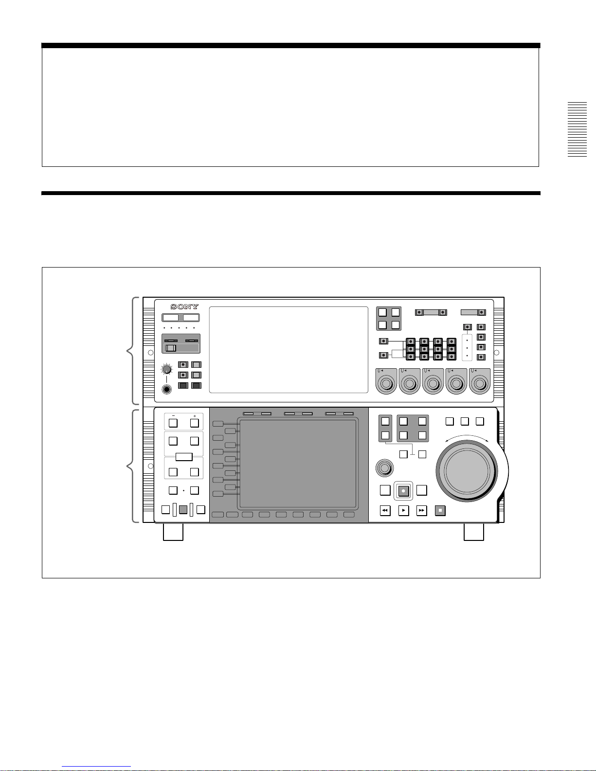
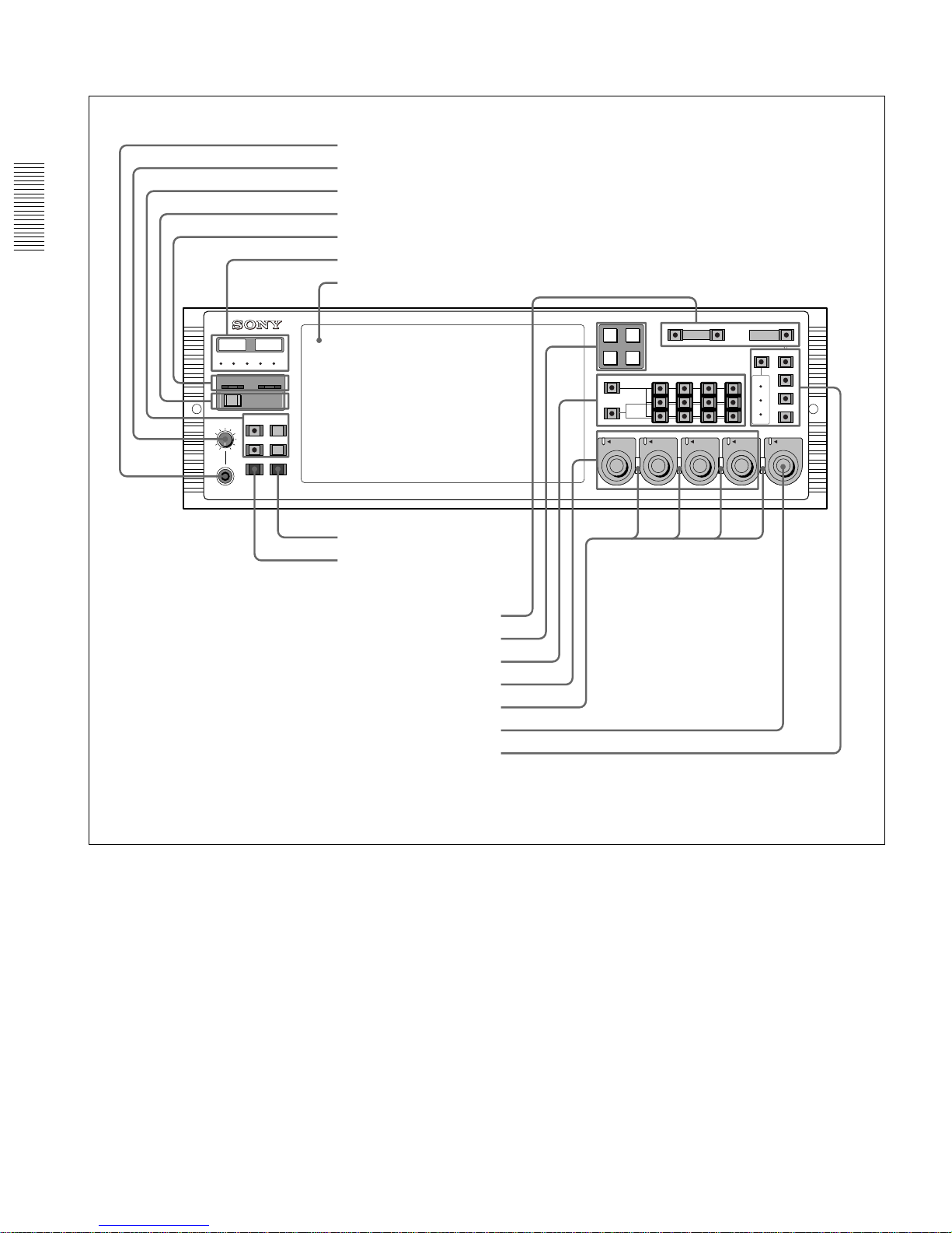
2-1 Front Pane l
The front panel of the MAV-777 is in two sections:
• Meter panel (upper)
• Control panel (lower)
F or mor e information a bout the contr ol panel, r efer to Volume II (Editing Operations from the
Control Panel) of this operation manual.
50P
9P
REMOTE
R1
PORT SELECT
R2/
P3
P1
INPUT
HD SDI
AES/EBU
CH1
CH1
PRESET
AUDIO INPUT / MONITOR SELECT
CH2 CH3 CH4
MONITOR
L
R
METER
PANEL
REMOTE
MENU
LOCAL
CONTROL
PANEL
SETUP BANK
TOTAL /
REMAIN
PROCESS
CONTROL
Y/
MASTER
PB
PR
SET UP
PHONES
123
SYSTEM HDD
HELP
FULL /
FINE
TC/UB
TIMER SEL
MENU
10
SET
0
CH2
PRESET
CH3
PRESET
CH4
PRESET
VIDEO/MENU
PRESET
R3/
P2
CONTROL PANEL
PANEL SELECT CHARACTER
REAR FRONT
1 2 3
NONE OFF ON80TH
SETUP
SELECT
IN OUT
PB EE PB
L1
L2
L3
L4
L5
L6
L7
L8
L9
L10
L11
B1 B2 B3 B4 B5 B6 B7
MODE SHIFT
IN
DMC EDIT
PREVIEW
AUTO EDIT
REVIEW
MEMORY
DELETE
OUT
TRIM
AUDIO
ENTRY
HOLD RESET TC/UB TC TYPE
1
2
EXT
R1
R2/
P3
PORT SELECT
P1
SHUTTLE
MULTI
CONTROL
PLAYER
PREROLL EDIT
REW PLAY F. FWD STOP
REC
RECORDER
JOG VAR
R
E
V
E
R
S
E
F
O
R
W
A
R
D
R3/
P2
Meter panel
Control panel
Front panel
Chapter 2 Names and Functions of Parts
2-2 (E) 2-1 Front Panel
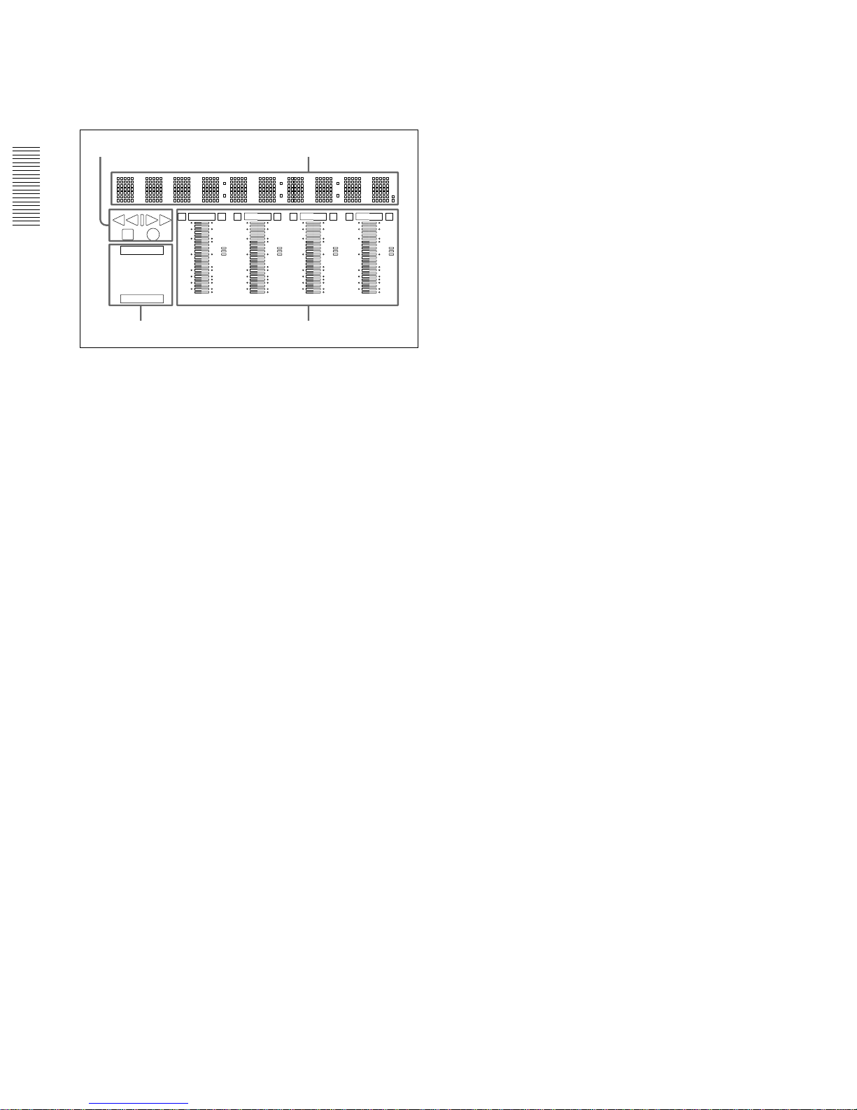
2-1-1 Meter Panel
REMOTE
R1
PORT SELECT
R2/
P3
P1
INPUT
HD SDI
AES/EBU
CH1
CH1
PRESET
AUDIO INPUT / MONITOR SELECT
CH2 CH3 CH4
MONITOR
L
R
METER
PANEL
REMOTE
MENU
LOCAL
CONTROL
PANEL
SETUP BANK
TOTAL /
REMAIN
PROCESS
CONTROL
Y/
MASTER
PB
PR
SET UP
PHONES
123
SYSTEM HDD
HELP
FULL /
FINE
TC/UB
TIMER SEL
MENU
10
SET
0
CH2
PRESET
CH3
PRESET
CH4
PRESET
VIDEO/MENU
PRESET
R3/
P2
9P
50P
a PHONES jack
b PHONES control
c Display selection section
d HELP button
e ERROR/WARNING indicators
f LED indica tors
g Display panel
h SET button
i MENU button
j REMOTE/LOCAL setting section
k PORT SELECT button
l AUDIO INPUT SELECT/MONITOR SELECT section
m AUDIO REC/PB LEVEL ADJUST KNOB
n PB/REC indicator s
o VIDEO/MENU control
p VIDEO PROCESS setting section
Meter panel

Chapter 2 Names and Functions of Parts
2-1 Front Panel 2-3 (E)
a PHONES jack
By connecting stereo headphones with an impe dance
of 8 ohms to this jack, you can monitor the sound
during recording, playback, and editing. This
monitors the sound on the channels selected for
monitor output on the currently selected port (using
the POR T SELECT b utton s (k) and A UDIO INPUT
SELECT/MONITOR SELECT buttons (l)). Adjust
the monitor volume with the PHONES control (b).
b PHONES control
This adjusts the volume of the outp ut from the
PHONES jack.
c Display selection section
TO TAL/REMAIN (remaining) button
Displays the total time of the files of material held on
the HDD (Sys Total), the remaining available HDD
capacity (Sys Remain), and the time remaining of the
material currently being played/recorded for each
port on the display panel (g). The button lights up
when these are displayed.
FULL/FINE button
Selects the range of the audio level meter on the
display panel (g) for the port currently selected by
the PORT SELECT button (k).
FULL: The le vel meter r ange is -60 dB to 0 dB or -40
dB to +20 dB. A setup menu item determines
which of these ranges is used (peak value 0 d B or
+20 dB).
FINE: The level meter display range is magnified, to
display 0.25 dB steps. If the audio level goes
above the maximum display range, the top
segment flashes; if the audio level goes below the
minimum display range, the bottom segment
flashes.
TIMER SEL (time data display select) button
This selects the type of time data displayed on the
display panel (g) for the currently selected port.
When normal time data (one of LTC, VITC, TM1,
and TM2) is displayed, pressing the TIMER SEL
button cycles the display through the sequence LTC
t VITC t TM1 t TM2 t LTC ...
When user bit values are displayed, pressing the
TIMER SEL button togg les betw een LTC and VITC
user bit informat ion.
TC/UB (timecode/user bit s) button
When this button is pressed, turning it on, the user bit
information in the timecode signal on the currently
selected port appears on the display panel.
When the TIMER SEL selection being displayed is
LTC or VITC, then the user bit information from the
corresponding timecode signal is displayed.
Pressing the TC/UB button again when the user bit
information is displayed turns the button off, and
returns the display to normal timecode (i.e. not the
user bits).
d HELP button
If a fault occurs in the system (either Error or W arning
level), press this button to display deta ils of the
problem on the display panel. If more than one error
or warning condition exists simultaneously, press the
HELP button repeatedly to step through the
corresponding displays.
After display of the Error/Warning status
information, the cur re nt opera ti on mode of the MAV777, the cumulati ve operati ng time, and the ref erence
with which the output system’s video reference is
synchronized are displayed in succession on the
display panel. Pressing the HELP button when no
fault has occurred displays only this information.
e ERROR/WARNING indicators
SYSTEM indicator
If a fault occurs in the system (either Error or W arning
level), this indicator flashes red. During normal
operation it lights green. Wh en it is flashing red, you
can press the HELP button (d) to display details of
the problem on the display panel.
HDD indicator
This indicator flashes green during access to the
HDD. If a fault (either Error or Warning le vel) occurs
in a HDD, this indicator flashes red. When it is
flashing red, you can press the HELP button (d) to
display details of the problem on the display panel.
f LED indicators
Operating panel indicators
These indicate which control panel can be operated:
the METER PANEL indicator refers to the unit’s
meter panel, and the CONTROL PANEL indicator
refers to the control panel. Each indicator lights
independently when the corresponding panel is
enabled, and goes off when the panel is disabled.
Further, operable panel settings can be enabled
through the unit’s system setup panel.
MENU BANK indicators
The indicator lights that corresponds to the currently
valid SETUP MENU BANK. The SETUP MENU
BANK is selected from the unit’ s system set up panel.
All the LED indicators light when reading from or
saving to the memory card.
For details, refer to Section 2-2, “System Setup Panel” (page
2-7).
When the ERROR/WARNING indicator blinks r ed, refer to
the “Error Messages” appendix (page A-2).
Chapter 2 Names and Functions of Parts
2-4 (E) 2-1 Front Panel
g Display indicators panel
The display panel provides four sets of identical
information, for each of the ports which can be used.
The following f i gure shows one of these displays.
Time data indication
This shows time data value for the corresponding
port. When you press the MENU button it also shows
setup menu items, and information about Error/
Warning states.
Status indication
This shows the operating status of the port, as follows.
Play................................................................. B
Stopped........................................................... x
Recording ...................................................... z
Variable speed playback (FWD)
at less than 1× speed....................................... B
Variable speed playback (REV)
at less than 1× speed....................................... b
Fast forward or variable speed playback
exceeding 1× speed ........................................ BB
Rewind or variable speed reverse playback
exceeding 1× speed ........................................ bb
Indicators
These show the type of timecode displayed, the
remote/local setting, whether recording is inhibited,
and so forth.
• REC INHIBIT
This appears when recording is inhibited on a
recording port. The recording inhibit setting is
carried out by a setup menu item.
• Time data type
This appears as LTC, VITC, TM1, or TM2,
according to the type of time data currently bei ng
displayed. When user bits from LTC or VITC are
displayed, the UB indicator also appears.
• Remote/local setting
This shows whether the port is set to LOCAL or
REMOTE.
•Port status
When the port is operating normally , the READ Y
indicator appears.
Audio level meters
These show the audio levels for each of the channels
for the currently displayed port (either recording
levels or playback levels as appropriate). When
playing back material recorded with emphasis on, the
“E” indicator appears for the corresp onding ch annel.
Either the FULL mode display (with two possible
range selections) or the FINE mode display is
available. To change the FULL/FINE selection, use
the FULL/FINE button in the display selection
section (c). Setup menu items determine the scale
and headroom settings.
h SET button
Press this button after changing a setup menu item.
i MENU button
Pressing this button li ghts the indi cator, and displays
a setup menu item. Press on ce again to cle ar the menu
display without changi ng the setting.
j REMOTE/LOCAL setting section
REMOTE button: Each time you press this button,
the currently selected port alternates between
REMOTE (Remote mode) and LOCAL (Local
mode). When in Remote mode, the button lights;
when in Local mode, it goe s out.
Local mode: The MAV-777 can only be controlled
from the control panel.
Remote mode: The device connected to the
connector panel
’s REMOTE IN connector (R1,
P1, R2/P3, R3/P2) or the PARALLEL I/O
connector controls the MAV-777.
When the Remote mode is sel ected, it is necessary to
press the 9P or 50P button t o specify the connector of
the external de vice that contr ols the MAV -777. W hen
the external device is connected to the REMOTE IN
connector (R1, P1, R2/P3, R3/P2), press the 9P
button. When the external device is connected to the
P ARALLEL I/O connector , press the 50P button. The
button that you press lights.
k PORT SELECT buttons
These select the port used for ti me data display,
audio/video input sour ce selection, and other settings.
The port selected by these buttons also determines the
port output from MONITOR OUTPUT.
E EOVER OVER OVER OVER
CH15
-60
-40
-30
-20
-10
dB
0
-40
dB
-20
-2
-10
0
10
1
-1
2
20
E E
CH26
-60
-40
-30
-20
-10
dB
0
-40
dB
-20
-2
-10
0
10
1
-1
2
20
E E
CH37
-60
-40
-30
-20
-10
dB
0
-40
dB
-20
-2
-10
0
10
1
-1
2
20
E E
CH48
-60
-40
-30
-20
-10
dB
0
-40
dB
-20
-2
-10
0
10
1
-1
2
20
READY
REC INHI
L TC VITC UB
TM1 TM2
REMOTE LOCAL
Status indication Time data indication
Indicators Audio lev el meters

Chapter 2 Names and Functions of Parts
2-1 Front Panel 2-5 (E)
l AUDIO INPUT SELECT/MONITOR SELECT
section
AUDIO INPUT SELECT/MONITOR SELECT
buttons
Select the input audio signals or monitor output
signals for the selected port. When the INPUT
SELECT button is lit select the input audio signals,
and when the MONITOR SELECT button is lit select
the monitor output signals.
INPUT SELECT button
Select the type and channel of the audio signal input
to the currently selected port. Press this button,
turning it on, then press the re quired AUDIO INPUT/
MONITOR SELECT button to assign the type and
channel.
HD SDI (C H1 to CH4 ): Select audi o signals input to
the HD SDI INPUT connectors.
AES/EBU (CH1 to CH4): Select audio signals input
to the AUDIO INPUT connectors.
• If no signal is present on the selected channel the
corresponding button wil l flash.
• If no HD SDI video input signal is present, the
INPUT SELECT button will flash.
MONITOR SELECT buttons
Select the audio signals monitored on th e MONITOR
OUTPUT L and R connectors. Press these buttons,
turning them on, then press selected of the AUDIO
INPUT/MONITOR SELECT buttons to assign
channels to the MONITOR OUTPUT L and R
outputs. If you assign more than one of the channels
(channels 1 to 4) to the same monitor out put channels,
the channels are mixed to form the monitor output.
m A UDIO REC (recording)/PB (playback) LEVEL
controls
These adjust the recording or playback le vels for each
of the four channels on the currently selected port. If
the currently selected port is a recording port, these
control the recording le vel, and if a playback port, the
playback level. To make an adjustment, first push in
the knob, so that the PRESET indicator goes off.
While the PRESET indicator is lit, the level is fixed at
the preset value, and cannot be adjusted.
n PB/REC indicators
These light red when the currently selected port is a
recording port, and green when th e currently selected
port is a playback port.
o VIDEO PROCESS/MENU control
While the indicator of the MENU button (i) is lit,
this is used to select an item in the se tup menu. For
menu operation, please refer to Section 3-4, “Setup”.
While the indicator o f the MENU button is off, this
carries out the VIDEO PROCESS adjustment
according to the VIDEO PROCESS setting mode
currently selected in the VIDEO PROCESS setting
section (p). The adjustment is only possible if both
of the following conditions are met:
• The VIDEO PROCESS control mode is set to
LOCAL
• The PRESET indicator to the top left of the knob is
off
While the PRESET indicator is lit, the preset value for
the currently selected VIDEO PROCESS setting
mode is used, and adjustment is not possible. By
pushing in the knob, the PRESET ind ica to r g oes off,
and adjustment is then possible.
p VIDEO PROCESS setting section
The four buttons on the right (Y/MASTER, PB, PR,
and SETUP) are used to select the corresponding
VIDEO PROCESS setting modes. Pressing one of the
buttons lights the indicator showing that the
corresponding VIDEO PROCESS setting mode is
selected. Adjustments of the VIDEO PROCESS
setting modes are made with the VIDEO PROCESS
control (o). Adjustments only affect the HD SDI
output for the currently selected playback port and
down-converted output. When making adjustments,
the HD SDI output and down-converted output
change simultaneously.
Adjustments to VIDEO PROCESS only take effect
upon playback of a file. When you unload a file, use
STILL or STOP, adjustments take effect but the
output does not change.
Y/MASTER (Y or Mast er ou tput level
adjustment) button
Pressing this button l ights the indicator and allo ws the
VIDEO PROCESS control (o) to adjust the Y (or
Master) output level. If the Y/MASTER button is
pressed by itself, the Y outp ut level can be adjusted,
and if the Y/MASRTER and PB buttons are pressed
simultaneously, the Master output level can be
adjusted. The Y/MASTER button lights during Y
output level adjustment, whereas the Y/MASTER
button light s along with the PB a nd PR butto ns during
Master output level adjustment. The current Y (or
Master) output le vel is display ed in the vici nity of th e
button.
PB button
Pressing this button l ights the indicator and allo ws the
VIDEO PROCESS control (o) to adjust the PB

Chapter 2 Names and Functions of Parts
2-6 (E) 2-1 Front Panel
output level. The current PB output level appears
around the control.
PR button
Pressing this but ton lights the indicator and al lows the
VIDEO PROCESS control (o) to adjust the PR
output level. The current PR output level appears
around the control.
SET UP button
Pressing this but ton lights the indicator and al lows the
VIDEO PROCESS control (o) to adjust the SET UP
output lev el. The current SET UP output lev el appears
around the control.
PROCESS CONTROL button
This sets the VIDEO PROCESS control mode for the
selected port. Each time you press the button, the
control mode cycles through REMOTE, MENU,
LOCAL, REMOTE, and so on. The current mode is
shown by the PROCESS CONT ROL MODE
indicators.
PROCESS CONTROL MODE indicators
These show the current VIDEO PROCESS control
mode for the selected port.
REMOTE: The internal digital video processor is
controlled with the HD Digital Video Controller
HKDV-503/900 (sold separately).
MENU: Indicates that the internal video processor is
under control of the Setup menu.
LOCAL: The internal video processor is controlled
by the VIDEO PROCESS control (o) on this
unit.
2-1-2 Control Panel
You can perform various editing operations from the
control panel on the bottom half of the front panel.
For details, refer to volume II of this operation manual.
Chapter 2 Names and Functions of Parts
2-2 System Setup Panel 2-7 (E)
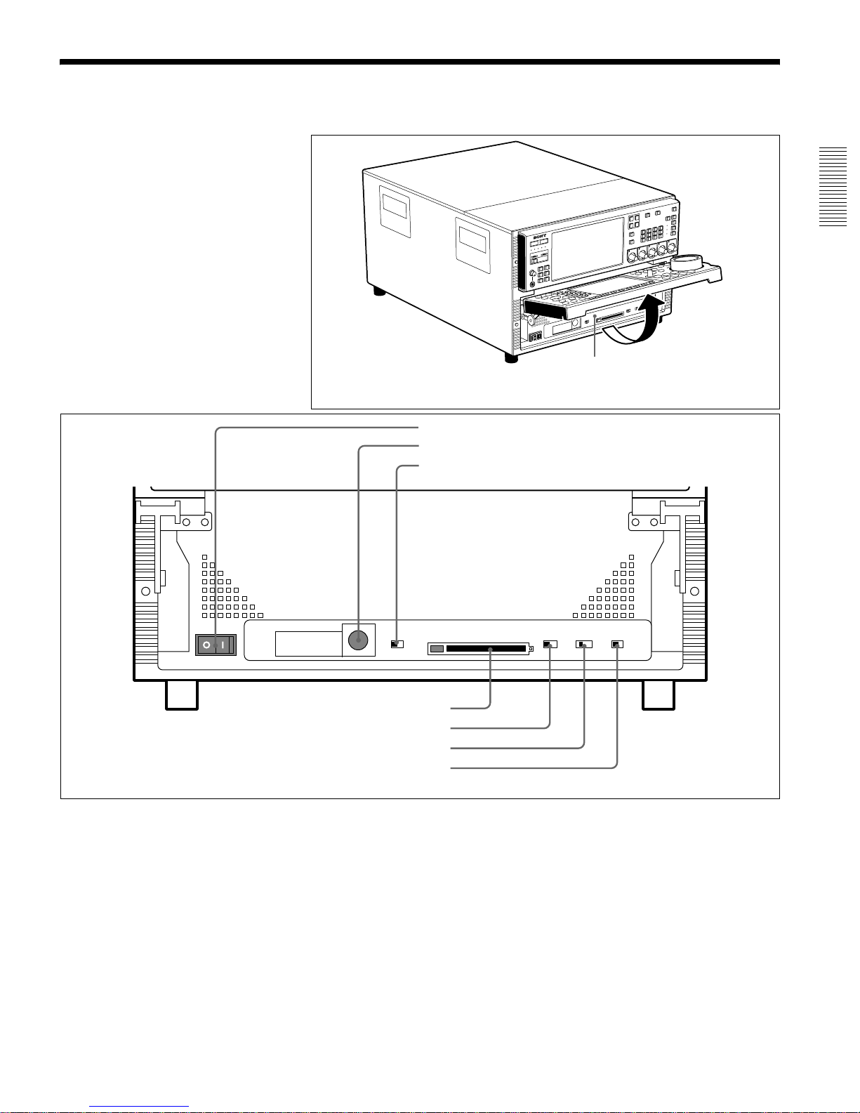
2-2 System Setup Panel
To operate the system setup panel, raise the control panel until it is horizontal.
a POWER switch
Set this to the ON posit ion to power on this unit.
b CONTROL PANEL connecto r
Connect the control panel.
c CONTROL PANEL switch
This selects whether the control pa nel is connected to
the connector on the front pane l or to the connector on
the rear panel. If there are control pa nels connected to
both connectors, this switch determines which is
enabled.
FRONT: Ordinarily, leave the switch in the FRONT
position.
REAR: If you need to use the MAV-777 with the
switch in the REAR position, please consult the
dealer from whom you purchased the equi pmen t
or a Sony sales representative.
d MEMORY CARD slot
Insert the memory card (sold separa te ly) in this slot.
Settings made on the Setup menu can be saved and
read on a memory card as required.
To remove the card, press the eject button next to the
slot.
System setup panel
Accessing the system setup panel
CONTROL PANEL
PANEL SELECT CHARACTER
REAR FRONT
1 2 3
NONE
ACCESS
MEMORY CARD
OFF ONBOTH
METER
PANEL
CONTROL
PANEL
SETUP
SELECT
a POWER switch
System setup panel
b CONTROL PANEL connector
c CONTROL PANEL switch
d MEMORY CARD slot
e SET UP SELECT switch
f P ANEL SELECT switch
g CHARACTER switch

Chapter 2 Names and Functions of Parts
2-8 (E) 2-2 System Setup Panel
Note
Do not eject the memory card while the ACCESS
lamp is lit as this may damage the information on the
memory card.
e SET UP SELECT switch
This selects the number of the menu bank for this
unit’s settings. The menu bank selected by changing
the switch setting becomes effective after the unit is
restarted. Howe ver , changes are not effecti ve if made
while the power is off do not become effective the
next time the power is turned on. In order to make the
changes effective, either cycle the power off and on
again, or reboot by means of the FAST REBOOT
item (item number 027) in the basic menu. The
currently v alid menu bank is indica ted by the MENU
BANK indicators. You can change the settings of the
current menu bank by pressing the MENU button to
display the setup menu. To change the settings of any
other bank, select the bank with the SET UP SELECT
switch while the setup menu is disp la yed.
For details of setup menus, see Section 3-4-1, “Basic Menu
Settings” (page 3-12).
f PAN EL SEL ECT switch
This switch enables or disables each of the meter
panels fitted as standard to th is unit and the control
panel. The switch settings are as follows.
NONE: Both of the control panels are disabled.
METER PANEL: The meter pa nel on ly is ena bl e d.
CONTROL PANEL: The control panel only is
enabled.
BOTH: Both of the control panels are enabled.
g CHARA CTER switch
This switch selects whether or not timecodes and
other character information is superimposed on the
video signal output from the MONITOR OUTPUT
connector.
ON: Superimposed information is output .
OFF: Superimposed information is not output.
The factory default setting is ON.
* When the basic menu item ANALOG MONITOR
SUPERIMPOSE (menu 008) is set to “inhibit”,
superimposition cannot be enabled from the
ANALOG COMPOSITE (SUPER) connector.
Chapter 2 Names and Functions of Parts
2-3 Connector Panel 2-9 (E)
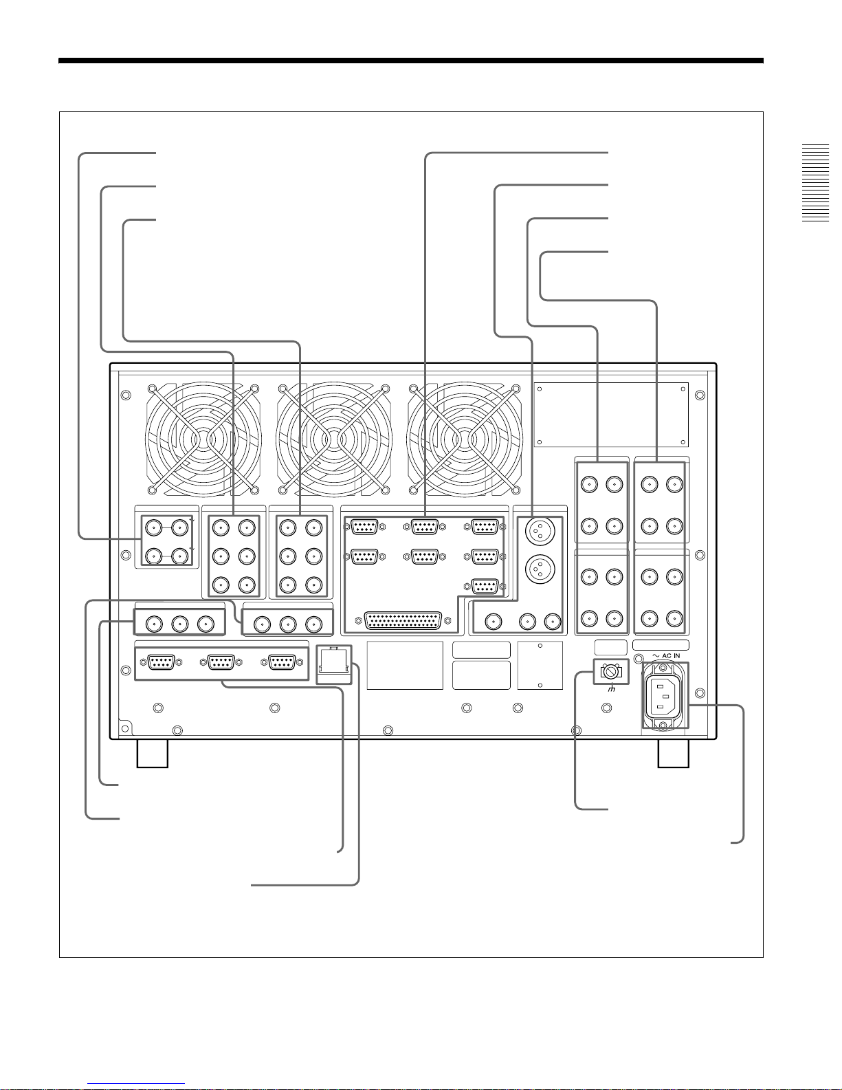
2-3 Connector Panel
IN –––––––– SD–––––––– OUT
REFERENCE
IN –––––––– HD –––––––– OUT
TIME CODE IN
VIDEO CONTROL (REMOTE)
R2R1 SYSTEM
TIME CODE OUT
P2P1 P3
AUDIO IN (AES/EBU)
CH1/2 ––––––– R1 ––––––– CH3/4
CH1/2 ––––––– R2 ––––––– CH3/4
CH1/2 ––––––– R3 ––––––– CH3/4
AUDIO OUT (AES/EBU)
CH1/2 ––––––– P1 ––––––– CH3/4
P1
MONITOR OUTREMOTE
SD SDI
(SUPER)
ANALOG
COMPOSITE
(SUPER)
HD SDI
(SUPER)
R1
HD SDI IN
INPUT MONITOR
HD SDI OUT
21
D CONV SDI OUT
2 (SUPER)1
D CONV
SDI OUT (SUPER)
SPARE
P2R2
HD SDI IN
INPUT MONITOR
HD SDI OUT
21
D CONV SDI OUT
2 (SUPER)1
D CONV
SDI OUT (SUPER)
SPARE
CH1/2 ––––––– P2 ––––––– CH3/4
CH1/2 ––––––– P3 ––––––– CH3/4
L
R
IN2(P1)
IN4(R3/P2)
TO MAVE-F555
IN/OUT1(VTR)
IN/OUT2(VTR)
IN1(R1)
IN3(R2/P3)
PARALLEL I/O(50P)
P1 P2 P3
10 BASE-T
Connector panel
a REFERENCE
connectors
b AUDIO IN connectors
c AUDIO OUT connectors
d TIME CODE IN connectors
e TIME CODE OUT connectors
f
VIDEO CONTROL (REMOTE) connector
g 10 BASE-T connector
h REMOTE connectors
i MONITOR OUT connectors
j HD SDI IN connectors
k HD SDI OUT connectors
l Ground terminal
m -AC IN connector

Chapter 2 Names and Functions of Parts
2-10 (E) 2-3 Connector Panel
a REFERENCE connectors (BNC type)
HD connector
Input an HD reference video signal. Input bipolar
(positive and negative) 3-value sync signals at this
connector. Bridge connection possible.
SD connector
Input a reference video signal. Input a signal with
chrominance burst (VBS). Bridge connection
possible.
To alternate between HD and SD, set the
“EXTERNAL REF SELECT” expansion menu item
(menu 121).
b AUDIO IN (AES/EBU Digital Audio Input)
connectors (BNC type)
These jacks input digital audio signals in the AES/
EBU format. Up to three inputs can be supported.
c AUDIO OUT (AES/EBU) connectors (BNC
type)
These jacks output digi tal audio sign als in the AES/
EBU format. Up to three outputs can be supported.
d TIME CODE IN (Time Code Input) connectors
(BNC type)
This is the input jack that is used when reco rding time
codes from an external de v ice. This jac k connects to
the time code output jack on the external device.
The input (SYSTEM, R1/R2, or HD SDI Embedded)
that is used for time code recording on the various
recording ports is selected in the “LTC SELECT”
expansion menu item (menu 670, 671, and 672).
Howev er, when the configurati on is 3 inp ut/1 o utput ,
either SYSTEM or HD SDI Embedded is always used
at the R3 port.
Note
The TIME CODE IN (SYSTEM) jack supports only
a 1× time code signal. The error message “TM
Warning LTC” appears if any other signal is input.
e TIME CODE OUT connectors (BNC type)
These connectors output playback time codes.
f VIDEO CONTROL (REMOTE) connector
When controlling the inter nal digital vi deo processor
from a remote location, connect the HD digital video
controller HKDV-503/900 (sold separately) to this
connector.
g 10 BASE-T connector
In order to control the MAV-777 from an external
device that is connected via Ethernet*, connect this
connector to the exter n al device with an Ethernet
cable.
When using a LAN cable: For safety, do not connect
to the connector for peripheral device wiring that
might have excessive voltage.
* Ethernet is a registered trademark of the XEROX
Corporation.
h REMOTE (Remote Control Input/Output)
Connectors
REMOTE I N con n ecto r (R1 , P1 , R2 /P3, R 3/P 2)
When controlling the MAV-777 through an external
device, use the 9-pin r emote cont rol cable to connec t
this connector to the external device.
REMOTE IN/OUT connector (1, 2)
When controlling an external device from the MAV777, use the 9-pin remote control cable t o connect the
external device to this connector.
TO MAVE-F555 connector
When controlling the MAV-777 from the MAVEF555, use the 9-pin remote control cable to connect
this connector to the MAVE-F555.
PARALLEL I/O connector (D-SUB 50 pins)
The remote control signals from an external device
are connected to this connector.
For details, refer to the installation manual.
i MONITOR OUT connectors (BNC type, XLR-
3-31)
Output video and audio monitor signals for the port
currently selected on the front panel. The XLR
connectors (L/R) output the audio monitor signal, and
the HD S DI, SDI, and AN A LOG c onne cto rs ou tput a
video signal including superimposed information.
Audio monitor output connectors
There are two audio outputs, L and R. The channels
output are selected with the meter panel’ s MONITOR
SELECT buttons and AUDIO INPUT/MONITOR
SELECT buttons.
HD SDI (SUPER) connector
Output a HD serial digital video signal. Cannot outp ut
audio signals from this connector.

Chapter 2 Names and Functions of Parts
2-3 Connector Panel 2-11 (E)
SD SDI (SUPER) connector
This outputs an SD serial digital video/audio signal.
The audio output signals output b y this connect or are
as follows:
CH1: Audio monitor output. Same as the Lch
signal.
CH2: Audio monitor output. Same as the Rch
signal.
CH3: No output
CH4: No output
If the CHARACTER switch on the system setup
panel is set to ON, timecode information and menu
settings appear as text superimposed on the video
signal.
ANALOG COMPOSITE (SUPER) connector
This outputs an analog composite video signal.
If the CHARACTER switch on the system setup
panel is set to ON, timecode information and menu
settings appear as text superimposed on the video
signal.
j HD SDI IN (Serial Video/Audio Input)
connectors (B NC type)
Input HD serial digital video and audio signals. A
maximum of three inputs (R1/R2/R3) is possible.
R1, R2, R3
HD SDI IN connector
Input HD serial digital video and audio signals.
HD SDI INPUT MONITOR connector
The input monitor connector. This line does not
conform to HD SDI standards.
SPARE connector
Spare connector for future functions. (Not used at
present.)
D CONV (Down Converter) SDI OUT (SUPER)
connector
The HD SDI input’s down converter output monitor
connector.
To turn character infomation on and off, make
settings in the “SUPERIMPOSE” basic menu item
(menu 053, 054, 055)
k HD SDI OUT (Serial Video/Audio Output)
connectors (B NC type)
Output HD serial digital video and audio signals. A
maximum of three outputs (P1/P2/P3) is possible.
P1, P2, P3
HD SDI OUT 1 and 2 connectors
Output HD serial digital video and audio signals.
D CONV (Down Converter) SDI OUT 1
connector
The HD SDI outputs down converter output monitor
connector.
D CONV (Down Converter) SDI OUT 2
(SUPER) conn ector
The HD SDI outputs down converter output monitor
connector.
To turn character infomation on and off, make
settings in the “LINE SU PERIMPOSE” basic menu
item (menu 050, 051, 052)
l Ground terminal
Connect to ground as required.
m - AC IN connector
Connect to a power outlet using the power cord (Part
Number: 1-776-997-11) (sold separately).

Chapter 3 Preparations
3-1 Overview of Operation Modes 3-1 (E)
Chapter 3 Preparations
3-1 Overview of Operation Modes
This unit provides the following four operation modes.
• Panel mode: Control by the control panel or a player port on the
editor.
• DTR + Panel mode: Replay and slow-motion playback using one camera
(“Replay & Slow 1”)
• DTR + DTR mode: Replay and slow-motion playback using two cameras
(“Replay & Slow 2”)
• BVE mode: This unit functions together with a VTR recorder.
This section summarizes the functions and descri bes the option configurations for
each operation mode.
The operation mode is selected by the basic menu item “SYSTEM OPERATE
CONFIGURATION” (menu 019). For details of the procedure for basic menu operations, see
Section 3-4, “Setup” (page 3-12).
For details of the me th od s of c on ne c tin g external devices for ea ch of the operation mo de s, see
Section 3-2, “Con necting External Devices” (page 3-7).
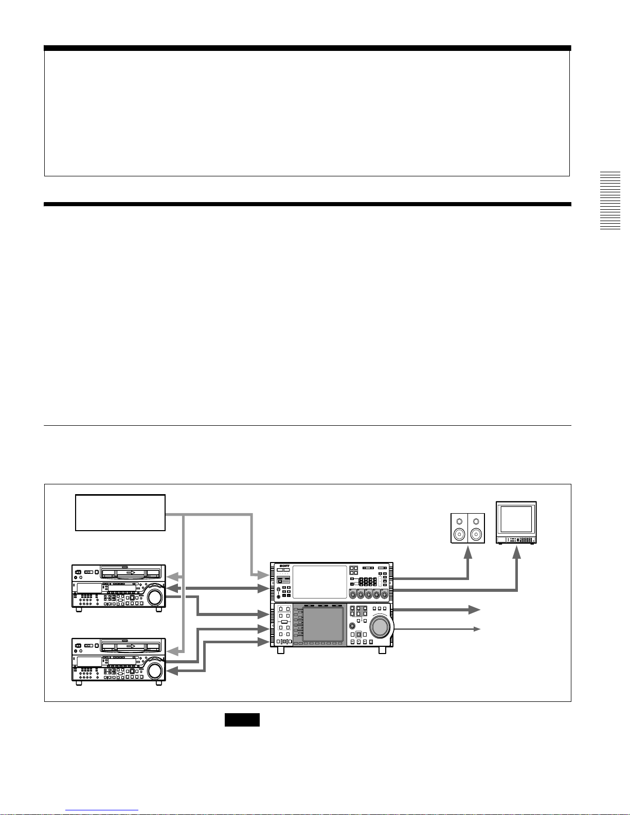
Panel Mode
In this mode, the input and output ports are controlled independently from the
MAV -777 control panel or from the player port of the editor . Ho weve r, an e xternal
device cannot be selected as the recorder.
Note
When editing, set expansion REFERENCE SELECT (menu 349, 350, 351) to
“output ref”.
CONTROL PANEL
PANEL SELECT CHARACTER
REAR FRONT
1 2 3
NONE OFF ON80TH
SETUP
SELECT
REMOTE
R1
PORT SELECT
R2/P3R3/
P2
P1
INPUT
HD SDI
AES/EBU
CH1
CH1
PRESET
AUDIO INPUT / MONITOR SELECT
CH2 CH3 CH4
MONITOR
L
R
METER
PANEL
REMOTE
MENU
LOCAL
CONTROL
PANEL
SETUP BANK
TOTAL /
REMAIN
PROCESS
CONTROL
Y/
MASTER
PB
PR
SET UP
PHONES
123
SYSTEM HDD
HELP
FULL /
FINE
TC/UB TC TYPE
MENU
10
SET
0
CH2
PRESET
CH3
PRESET
CH4
PRESET
VIDEO/MENU
PRESET
IN OUT
PB EE PB
L1
L2
L3
L4
L5
L6
L7
L8
L9
L10
L11
B1 B2 B3 B4 B5 B6 B7
MODE SHIFT
IN
DMC EDIT
PREVIEW
AUTO EDIT
REVIEW
MEMORY
DELETE
OUT
TRIM
AUDIO
ENTRY
HOLD RESET TC/UB TC TYPE
1
2
EXT
R1
R2/
P3
PORT SELECT
P1
SHUTTLE
MULTI
CONTROL
PLAYER
PREROLL EDIT
REW PLAY F. FWD STOP
REC
RECORDER
JOG VAR
R
E
V
E
R
S
E
F
O
R
W
A
R
D
Monitor
REF.
REF. REF.
LTC
HD SDI
monitor
HD SDI
RS 422
RS 422
HD VTR
HD VTR
To VTR or Server
MAV-777
Sync Generator
R3/
P2
9P
50P
REMOTE
2 input/2 output conf iguration example
Chapter 3 Preparations
3-2 (E) 3-1 Overview of Operation Modes
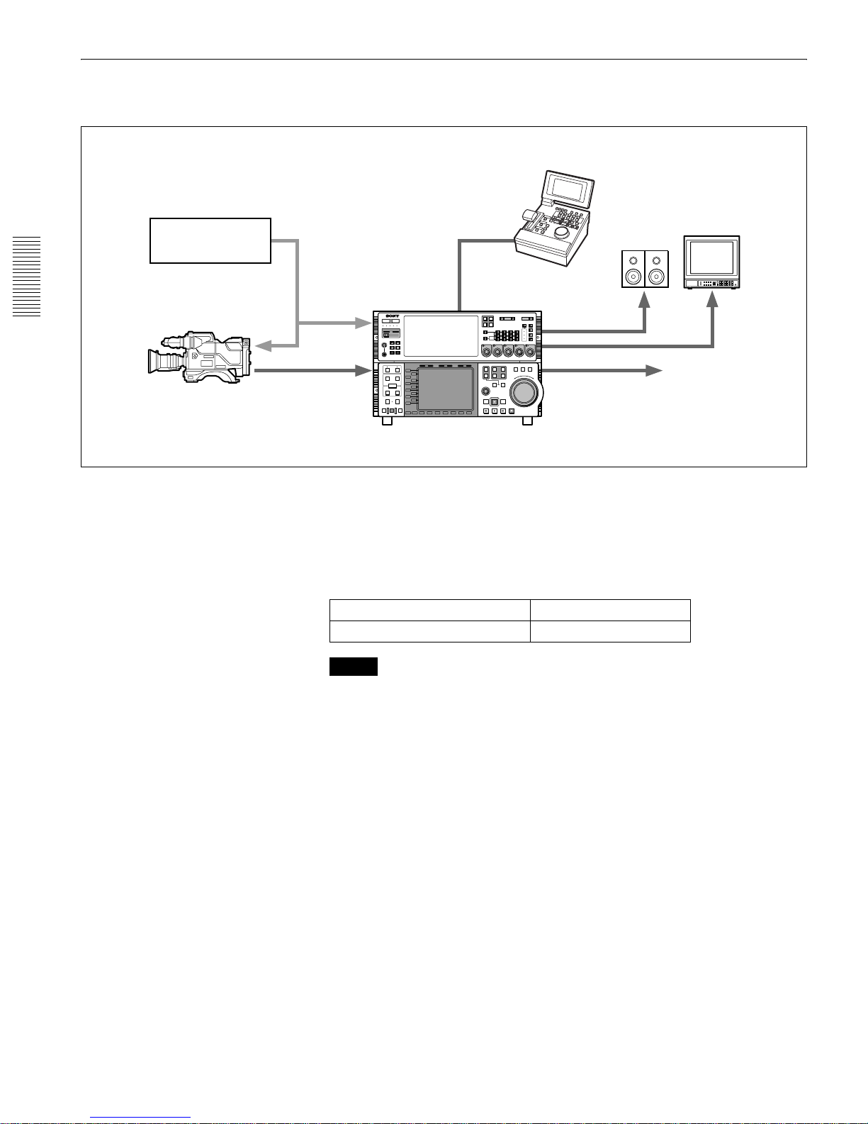
DTR + Panel Mode
This mode allows a single camera to be used for a live relay, with replay and slowmotion playback during recording.
This example assumes ports R1 and P1 are controlled from a DTR-3000.
Use the basic menu item LIVE DURATION (menu 034) to set the recording time
for port R1.
F or details on basic menu settings and operation sequences, refer to Section 3-4, “Setup” (page
3-12).
When using the control panel, the fol lowing p orts can be contr olled depending on
the settings of the basic menu PORT CONFIGURATION (menu 042).
Notes
• When using a DTR-3000 with this unit, the DTR-3000 version must be
CP:V01.30, VS:V01.20, or later. Further, the unit must be used in the
DISK:INDIVIDUAL mode. For details, please contact the company from
which you purchased the unit.
• To change from another operation mode to this mode, execute the -ALL
ERASE (menu 099) basic menu item and then reboot.
• When the LIVE DURATION time value is changed, or when recording from
the beginning of t he recording area, ex isting material must be erase d. Delete the
“LIVE1” material in the Panel mode and reboot to this mode, or reboot after
erasing all material using the -ALL ERASE (menu 099) basic menu item.
• Material recorded in this mode will be erased when this mode is again sel ected
from the Panel mode.
2 input/2 output ports R2 and P2 ports
1 input/3 output ports R2 and P3 ports
Configuration example
Dynamic Motion Controller
DTR-3000
Sync Generator
Video camera
REMOTE
R1
PORT SELECT
R2/P3R3/
P2
P1
INPUT
HD SDI
AES/EBU
CH1
CH1
PRESET
AUDIO INPUT / MONITOR SELECT
CH2 CH3 CH4
MONITOR
L
R
METER
PANEL
REMOTE
MENU
LOCAL
CONTROL
PANEL
SETUP BANK
TOTAL /
REMAIN
PROCESS
CONTROL
Y/
MASTER
PB
PR
SET UP
PHONES
123
SYSTEM HDD
HELP
FULL /
FINE
TC/UB TC TYPE
MENU
10
SET
0
CH2
PRESET
CH3
PRESET
CH4
PRESET
VIDEO/MENU
PRESET
Monitor
RS-422
REF.
HD SDI
monitor
HD SDI
MAV-777
REMOTE
50P
9P
CONTROL PANEL
PANEL SELECT CHARACTER
REAR FRONT
1 2 3
NONE OFFON80TH
SETUP
SELECT
IN OUT
L1
L2
L3
L4
L5
L6
L7
L8
L9
L10
L11
B1 B2 B3 B4 B5 B6 B7
MODE SHIFT
IN
DMC EDIT
PREVIEW
AUTO EDIT
REVIEW
MEMORY
DELETE
OUT
TRIM
AUDIO
ENTRY
1
2
EXT
R1
R2/
P3
PORT SELECT
P1
SHUTTLE
MULTI
CONTROL
PLAYER
PREROLL EDIT
REW PLAY F. FWD STOP
REC
RECORDER
JOG VAR
R
E
V
E
R
S
E
F
O
R
W
A
R
D
R3/
P2
 Loading...