

Page 1

EDITING PANEL
(for MAV-555 MULTI ACCESS VIDEO DISK RECORDER)
MAVE-F555
(Ver. 2.30)
電気製品は、安全のための注意事項を守らないと、火災
や人身事故になることがあります。
このオペレーションマニュアルには、事故を防ぐための重要な注意事項と製
品の取り扱いかたを示してあります。このオペレーションマニュアルをよく
お読みのうえ、製品を安全にお使いください。お読みになったあとは、いつ
でも見られるところに必ず保管してください。
OPERATION MANUAL
[Japanese/English]
1st Edition (Revised 2)
Serial No. 10001 and Higher
Page 2

WARNING
To prevent fire or shock hazard, do not
expose the unit to rain or moisture.
English
WARNING: Using this unit at a voltage other than 120 V
may require the use of a different line cord or
attachment plug, or both. To reduce the risk of
fire or electric shock, refer servicing to qualified
service personnel.
To avoid electrical shock, do not open the
cabinet. Refer servicing to qualified
personnel only.
THIS APPARATUS MUST BE EARTHED.
For the customers in the USA
WARNING
This equipment has been tested and found to comply with
the limits for a Class A digital device, pursuant to Part 15 of
the FCC Rules. These limits are designed to provide
reasonable protection against harmful interference when the
equipment is operated in a commercial environment. This
equipment generates, uses, and can radiate radio frequency
energy and, if not installed and used in accordance with the
instruction manual, may cause harmful interference to radio
communications. Operation of this equipment in a residential
area is likely to cause harmful interference in which case the
user will be required to correct the interference at his or her
own expense.
You are cautioned that any changes or modifications not
expressly approved in this manual could void your authority
to operate this equipment.
AVERTISSEMENT
Afin d’éviter tout risque d’incendie ou d’électrocution, ne pas
exposer l’appareil à la pluie ou à l’humidité.
Afin d’écarter tout risque d’électrocution, garder le coffret
fermé. Ne confier l’entretien de l’appareil qu’à un personnel
qualifié.
CET APPAREIL DOIT ÊTRE RELIÉ À LA TERRE.
VORSICHT
Um Feuergefahr und die Gefahr eines elektrischen Schlages
zu vermeiden, darf das Gerät weder Regen noch
Feuchtigkeit ausgesetzt werden.
Um einen elektrischen Schlag zu vermeiden, darf das
Gehäuse nicht geöffnet werden. Überlassen Sie
Wartungsarbeiten stets nur einem Fachmann.
DIESES GERÄT MUSS GEERDET WERDEN.
The shielded interface cable recommended in this manual
must be used with this equipment in order to comply with the
limits for a digital device pursuant to Subpart B of Part 15 of
FCC Rules.
This symbol is intended to alert the user to the
presence of important operating and maintenance
(servicing) instructions in the literature accompanying
the appliance.
WARNING: THIS WARNING IS APPLICABLE FOR USA
ONLY.
If used in USA, use the UL LISTED power cord specified
below.
DO NOT USE ANY OTHER POWER CORD.
Plug Cap Parallel blade with ground pin
(NEMA) 5-15P Configuration)
Cord Type SJT, three 16 or 18 AWG wires
Length Less than 2.5 m (8 ft. 3 in.)
Rating Minimum 10 A, 125 V
Page 3

For the customers in Europe
This product with CE marking complies with both the EMC
Directive (89/336/EEC) and the Low Voltage Directive (73/
23/EEC) issued by the Commission of the European
Community.
Compliance with these directives implies conformity to the
following European standards:
• EN60950: Product Safety
• EN55103-1: Electromagnetic Interference (Emission)
• EN55103-2: Electromagnetic Susceptibility (Immunity)
This product is intended for use in the following
Electromagnetic Enviroment(s):
E1 (residential), E2 (commercial and light industrial), E3
(urban outdoors) and E4 (controlled EMC environment, ex.
TV studio).
Pour les clients européens
Ce produit portant la marque CE est conforme à la fois à la
Directive sur la compatibilité électromagnétique (EMC) (89/
336/CEE) et à la Directive sur les basses tensions (73/23/
CEE) émises par la Commission de la Communauté
européenne.
La conformité à ces directives implique la conformité aux
normes européennes suivantes:
• EN60950: Sécurité des produits
• EN55103-1: Interférences électromagnétiques (émission)
• EN55103-2: Sensibilité électromagnétique (immunité)
Ce produit est prévu pour être utilisé dans les
environnements électromagnétiques suivants:
E1 (résidentiel), E2 (commercial et industrie légère), E3
(urbain extérieur) et E4 (environnement EMC contrôlé ex.
studio de télévision).
Für Kunden in Europa
Dieses Produkt besitzt die CE-Kennzeichnung und erfüllt
sowohl die EMV-Direktive (89/336/EEC) als auch die
Direktive Niederspannung (73/23/EEC) der EG-Kommission.
Die Erfüllung dieser Direktiven bedeutet Konformität für die
folgenden Europäischen Normen:
• EN60950: Produktsicherheit
• EN55103-1: Elektromagnetische Interferenz (Emission)
• EN55103-2: Elektromagnetische Empfindlichkeit
(Immunität)
Dieses Produkt ist für den Einsatz unter folgenden
elektromagnetischen Bedingungen ausgelegt:
E1 (Wohnbereich), E2 (kommerzieller und in beschränktem
Maße industrieller Bereich), E3 (Stadtbereich im Freien) und
E4 (kontrollierter EMV-Bereich, z.B. Fernsehstudio).
Page 4

Table of Contents
Chapter 1
Overview
Chapter 2
Preparations
1-1 MAVE-F555 Overview .................................................................. 1-1
1-2 Principal Features .......................................................................... 1-2
1-3 Changes from Version 1.00 ........................................................... 1-4
1-3-1 Version 1.00 to 1.10 Changes .............................................. 1-4
1-3-2 Version 1.10 to 2.00 Changes .............................................. 1-5
1-3-3 Version 2.00 to 2.10 Changes ............................................. 1-6
1-3-4 Version 2.10 to 2.20 Changes ............................................. 1-6
1-3-5 Version 2.20 to 2.30 Changes .............................................. 1-7
1-4 Names and Functions of Parts....................................................... 1-9
1-4-1 Console ................................................................................ 1-9
1-4-2 Rear Panel Connectors ....................................................... 1-12
2-1 Example System Configurations and Device Connections ......... 2-1
2-1-1 Example System Configuration (1)
- for Linear/Nonlinear Editing ............................................. 2-1
2-1-2 Example System Configuration (2)
Connecting Multiple MAVE-F555 Units to the MAV-555. 2-2
2-1-3 Connecting the MAVE-F555 and MAV-555 ...................... 2-3
2-2 Settings on the MAV-555 ............................................................... 2-5
2-2-1 Operation Mode Setting ....................................................... 2-5
2-2-2 Port Settings ......................................................................... 2-5
2-2-3 Settings for Superimposed Indications ................................ 2-5
2-2-4 Settings for Changing File Times ........................................ 2-6
2-2-5 Settings with the MAVE-D555 ............................................ 2-6
Chapter 3
Operations for Linear/
Nonlinear Editing
3-1 Operations for Linear Editing (Operations in File Units) .......... 3-1
3-1-1 File Selection ....................................................................... 3-1
3-1-2 Creating a New File ............................................................. 3-6
3-1-3 Deleting Files ....................................................................... 3-8
3-2 Operations for Nonlinear Editing (Operations in Cut Units) .... 3-9
3-2-1 Cut Jump Function (Cueing Up to a Cut Point)................. 3-11
3-2-2 Save and Recall Cut Point Information ............................. 3-14
3-2-3 Editing Modes .................................................................... 3-18
3-2-4 Cut Insertion/Replacement
(Editing Using INSERT Mode) ......................................... 3-19
3-2-5 Cut Overwriting (Editing Using OVERWRITE mode) ..... 3-28
3-2-6 Deleting a Cut
(Editing Using LIFT mode and EXTRACT mode) .......... 3-34
3-2-7 Editing With Effects .......................................................... 3-38
3-2-8 External VTR Control ........................................................ 3-39
3-2-9 Trimming a Cut .................................................................. 3-41
3-2-10 Split Editing ....................................................................... 3-50
3-2-11 Editing Operation ............................................................... 3-53
3-2-12 IN Point and OUT Point Holding Periods ......................... 3-54
3-2-13 Undoing and Redoing an Editing Operation
(Undo/Redo) ..................................................................... 3-57
Table of Contents 3 (E)
Page 5

Table of Contents
3-3 Background Operation
(Recording/Playback Using the Spare Port) .............................. 3-59
3-3-1 MAV-555 Circuit Board Configuration and
Background Port ................................................................ 3-59
3-3-2 Background Recording ...................................................... 3-59
3-3-3 Background Playback ........................................................ 3-61
3-3-4 Restricting Background Port Operation ............................. 3-62
3-4 Recorder Selection Function ....................................................... 3-63
3-4-1 Settings on the MAV-555 .................................................. 3-64
3-4-2 Simple Switcher Function and Connection Configuration
External Notification Function .......................................... 3-66
3-4-3 Example Setting and Connections ..................................... 3-67
3-4-4 VTR Constant Settings ...................................................... 3-68
Chapter 4
Operations When Multiple
MAVE-F555 Units Are
Connected to the MAV-555
Appendixes
4-1 Allowed Operations ........................................................................ 4-2
4-2 Ports Being Controlled................................................................... 4-3
List of Error Messages ......................................................................... A-1
List of Superimposed Indications........................................................ A-5
Specifications....................................................................................... A-12
4 (E) Table of Contents
Page 6

About this Operation Manual
This section describes how to use this Operation Manual, which serves as a
guide to using the MAVE-F555 Editing Panel.
Purpose and intended readership of this manual
This Operation Manual describes the parts of the MAVE-F555 and their
functions, preparations, and general operations which you will need to
understand in order to use the MAVE-F555.
By using the Multi Access Video Disk Recorder MAV-555 together with the
MAVE-D555 or BVE-series Editor, you can easily create a linear-like
nonlinear editing system, or an edit/broadcast system with the MAV-555 as a
line acceptor in combination with a player. In this arrangement, the MAVEF555 acts as a controller for the MAV-555, MAVE-D555 and BVE-series
Editor as external devices. This operation manual is written based on the
assumption that you already have a basic understanding of how these external
devices function and how to use them.
When using the MAVE-F555, read this manual in conjunction with the
manuals supplied with the external devices connected to the MAVE-F555.
About this Operation Manual 5 (E)
Page 7

About This Operation Manual
Organization of this manual
To give an overall idea of the whole of this manual, the chapters from Chapter
1 and the Appendix are listed below.
Chapter 1 Overview
This briefly describes the principal features of the MAVE-F555 and the names
and functions of the parts of the MAVE-F555.
Chapter 2 Preparations
Regarding the use of MAVE-F555 with the MAV-555 Multi Access Video
Disk Recorder and MAVE-D555 or BVE-series editor, this chapter describes
example system configurations for different applications, how to connect the
MAVE-F555 to the MAV-555, and the settings required on the MAV-555.
Chapter 3 Operations for Linear/Nonlinear Editing
Regarding the use of the MAV-555 and MAVE-D555 or a BVE-series editor,
this chapter describes file operations which cannot execute from the BVEseries editor for the MAV-555: file assignment, creating new files, deleting
files, and cut-jump and cut-insertion operations. This chapter also describes
how to make efficient use of a spare MAV-555 port for background operation
from the MAVE-F555, and the recorder selection function for “one-touch”
switching of the VTR/MAV-555 player/recorder configuration.
Chapter 4 Operations When Multiple MAVE-F555 Units Are
Connected to the MAV-555
When two or more MAVE-F555 units are connected to the MAV-555, this
describes how to control different ports of the MAV-555 from the MAVEF555. It also describes which operations are possible from the MAVE-F555,
depending on the method of connection.
Appendixes
This includes a list of error messages and the principal specifications of the
MAVE-F555.
6 (E) About this Operation Manual
Page 8
Chapter 2 Preparations
2-3 (E)
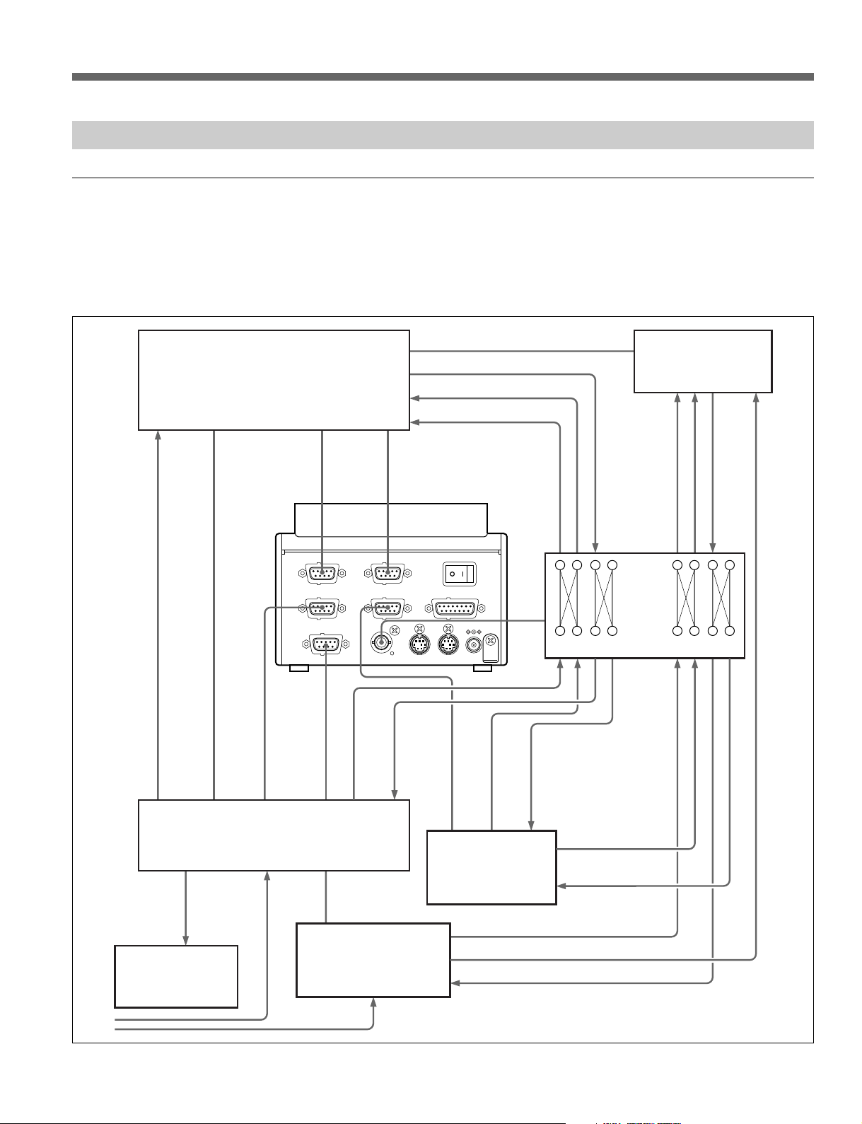
2-1-3 Connecting the MAVE-F555 and MAV-555
Connection with the TO MAV connector
To fully exploit the nonlinear editing, background operation, recorder selection
function, and other functions of the MAVE-F555, connect the TO MAV
connector of the MAVE-F555 to the REMOTE SPARE connector of the
MAV-555. Connections of other devices to the MAV-555 are the same as
when the MAV-555 operation mode is set to BVE mode.
IN1(EDITOR R)IN2(EDITOR P)POWER
OUT1(MAV P1
)
TO MAV
OUT2(VTR
)
1
TO MAV(PARALLEL I/O
)
DC IN(12V
)
2
D555 I/FAV SEL OUT
ANALOG IN1
ANALOG IN2
BKMA-570
MAV-555
MAVE-F555
BVE-600
MXP-29
VTR
AV SELECTOR
ANALOG OUT2
ANALOG OUT1
VIDEO IN COMPOSITE R2
VIDEO OUT COMPOSITE P2
REMOTE IN4(P2)
P2 REMOTE
R REMOTE
P1 REMOTE
R MIC /LINE IN
P1 MIC /LINE IN
LINE OUT
P2 MIC /LINE IN
REMOTE IN2(P1)
REMOTE IN
REMOTE SPARE
VIDEO OUT
COMPOSITE P1
VIDEO IN
COMPOSITE R1
ANALOG
COMPOSITE IN
ANALOG
COMPOSITE OUT
ANALOG
AUDIO OUT
RECORDER MONITOR
COMPOSITE VIDEO IN P1
VIDEO OUT
MIXER REMOTE EDITOR
ANALOG
AUDIO IN
MONITOR
OUT
For details of RS-422 connections between the MAVE-F555 and other devices, see
Section 3-4, “Recorder Selection Function” (page 3-63).
BVM-series or other
video monitor
How to use this manual
Chapter 3 Operations for Linear/Nonlinear Editing
3-11 (E)
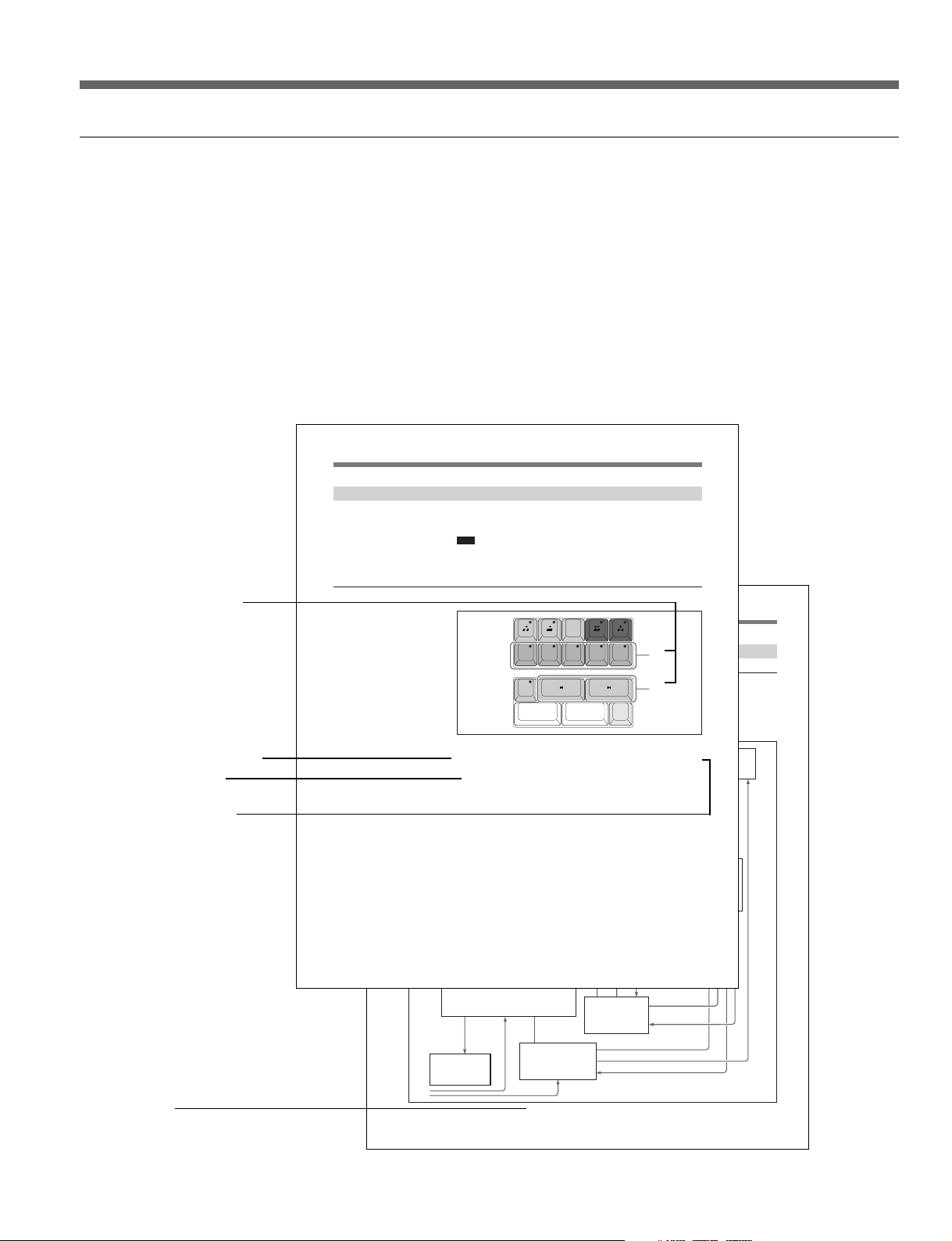
3-2-1 Cut Jump Function (Cueing Up to a Cut Point)
You can cue up to successive cut points in the file subject to editing loaded on
the MAV-555 port. This is termed a “Cut jump.”
Note
When the MAV-555 is turned off before saving the cut point information, the
information is cleared.
For details, see Section 3-2-2 "Save and Recall Cut Point Information" (page 3-14).
Cut Jumping on a Recorder Port
To perform a cut jump, use the following procedure.
1
Using the channel specification keys (V, A1, A2, A3, and A4), select the
channel on which you want to search for the cut point.
Press the key corresponding to the channel on which you want to search
for the cut point, turning on the indicator above the key. You can select
more than one channel.
1
2
Switches and other controls
used in the step described
below
Procedure descriptions
Numerals attached to buttons and switches in illustrations indicate the
corresponding steps of a procedure. They are also used to indicate switches
used in an operation, indicators which must be checked, information
superimposed on the monitor screen (the MONITOR OUT output of the
MAV-555), and so on.
Cross-references to related information in this manual or other documentation
are in italics, and show the item to be referred to and the page number. When
the related information is in a manual other than this manual, the crossreference gives the title of the other manual.
REDO
UNDO
V A1 A2 A3 A4
Step number within a procedure
Results of an operation or
other related information
Description of the operation
Cross-reference
TRIM
MARK
MARK OUTMARK IN
SPLIT
Example description
About this Operation Manual 7 (E)
Page 9

About This Operation Manual
Related manuals
In addition to this manual, the following manuals are provided for the
MAVE-F555.
• Installation Manual (supplied)
This describes the installation of the MAVE-F555.
• MAV-555 Series Maintenance Manual (option)
This describes the maintenance of the MAVE-F555.
8 (E) About this Operation Manual
Page 10

1-1 MAVE-F555 Overview
The MAVE-F555 is a dedicated editing panel intended for use with the
MAV-555 Multi Access Video Disk Recorder and MAVE-D555 or BVEseries editor that provides a range of functions that are efficient and easy to
use. The MAVE-F555 provides the following basic functions.
• File search, display, and selection functions for material on the MAV-555
• For edited material and material in course of editing on the MAV-555, cut
insertion, delete, and other nonlinear editing functions (independent
editing of the V/A1/A2/A3/A4 channels is possible)
• Background operation function using a spare MAV-555 port (recording
using the background port or playback of MAV-555 internal material)
• Expanded editor functions with the MAVE-D555 or BVE-series editor.
Notes
• When using the MAVE-F555 Ver. 2.30, you must use the MAV-555,
MAV-555A, MAV-555SS, or MAV-777 Ver. 2.32, and the MAVE-D555
Version 1.30.
• For reasons of simplicity, in this manual we refer to the MAV-555,
MAV-555A, MAV-555SS (SD mode), and MAV-777 as the MAV-
555.
Chapter 1 Overview
Chapter 1 Overview 1-1 (E)
Page 11

1-2 Principal Features
1-2 Principal Features
Linear editing support function
The MAV-555 handles material in units referred to as files. Therefore, to carry
out recording or playback using the MAV-555, operations corresponding to
loading a tape on a VTR are required, that is, creating a new file (for new
recording) or selecting an already recorded file (assignment). Using the
MAVE-F555, you can carry out operations which cannot be carried out from a
BVE-series editor, selecting or creating files on the MAV-555, and deleting
files. For a file on the MAV-555 selected using the MAVE-F555, you can
immediately use the search dial on the MAVE-D555 or BVE-series editor to
carry out a search.
Nonlinear editing functions
By using the MAVE-F555 with a MAVE-D555 or BVE-series editor to
operate the MAV-555, nonlinear operations such as adding or deleting cuts
(not possible with the conventional BVE-series alone) can be carried out. For
editing, you can select only the required channels from the V/A1/A2/A3/A4
channels. You can also use the cut jump function which allows you to cue up
sequentially to cut points in material being edited.
Background operations
Recorder selection function
Using the MAV-555 in BVE mode, there is a spare port not used for editing.
For example, if the MAV-555 is in the 2 input/2 output port configuration, the
R2 port of the MAV-555 is not used for editing, and is a spare port. Such a
“background port” can be controlled from the MAVE-F555. When the
background port is a recording port, you can use the port for recording
operations, and when a playback port, you can use the port for playback or
broadcasting operations on MAV-555 internal material.
When editing with an editing system of an MAV-555 and MAVE-D555 or
BVE-series editor, the following system configurations/connectors are
required:
(1) with the VTR as player and the MAV-555 as recorder, for creating the
editing result file in the MAV-555, and (2) with the MAV-555 as player and the
VTR as recorder, for returning the completed MAV-555 internal file to the VTR.
Using the recorder selection function, you can provide both of these with a
single system configuration/connection, switching by a simple MAVE-F555
button operation (pressing the MAV key or VTR key).
Depending on the settings in the MAV-555 setup menu, the devices/ports
controlled (by the P1 and P2 keys) when the MAVE-F555 MAV key is
selected, and the devices/ports controlled when the VTR key is selected can be
assigned freely. Further, depending on the MAV/VTR selection, the internal
connections of the MAVE-F555 RS-422 ports (IN1/IN2/OUT1/OUT2) can be
switched, and at the same time the connection switching status can be notified
from the A/V SEL OUT connector. Integrated use of these operations allows
you a system configuration, which as described above is characterized as
“nonlinear editing t transferring completed material to VTR,” and also
allows the use of other unique configurations.
1-2 (E) Chapter 1 Overview
Page 12

Support for connection of multiple MAVE-F555 units to a single MAV-555
Using the TO MAV (PARALLEL I/O) connector of the MAVE-F555, you can
connect more than one MAVE-F555 to a single MAV-555, and with different
MAVE-F555 units you can easily control different ports of the MAV-555.
For example, when the MAV-555 has a 1 input/3 output configuration, you
can configure a distribution system so that while recording on a line input to
the MAV-555, you can carry out file assignments on the three ports P1 to P3
from the three corresponding MAVE-F555 units.
Chapter 1 Overview 1-3 (E)
Page 13

1-3 Changes from Version 1.00
1-3 Changes from Version 1.00
1-3-1 Version 1.00 to 1.10 Changes
Cut Trimming
You can now trim the IN point and OUT point after executing the edit when
operating and editing a material captured on the MAV-555 using the MAVEF555 and a MAVE-D555 or a BVE-series editor. Either the results of previous
linear edit results from a BVE-series editor, or the nonlinear edit results from
the MAV-555 can be used for trimming operations.
Split Editing
When the MAV-555 is used in the BVE mode, with one edit different IN
points can be set for editing each channel for the Video and Audio channels.
Clearing IN and OUT Points
One setting now clears IN and OUT points.
Clearing Files Stored with the MEMORY Key
Files stored with the MEMORY key can now be cleared.
Improved Cue-up Points Following Edit Execution
In Version 1.00 the IN/OUT points specified for the target file on the Recorder
port were cleared immediately after edit execution, but in Version 1.10 new IN
points are set like cue-up points immediately after edit execution.
Successive Cut Jumps
When executing cut jumps with the [ B? ] or [ ?b ] keys by repeatedly pressing
either key, without conducting cue-up immediately cue-up will now execute at
the time specified from the end of key operation.
Revised Error Messages
Error messages have been revised along with the revised functions.
Improved Superimposed Text Display
The superimposed display was improved as each function was revised or new
functions added.
1-4 (E) Chapter 1 Overview
Page 14

1-3-2 Version 1.10 to 2.00 Changes
MAVE-D555 Compatibility
Connection to the MAVE-D555 has been enabled. The MAVE-D555 contains
all the functions of the BVE-series editor to provide continuity and also
provides new nonlinear editing capability.
Support for Effect Editing
Corresponds to the DISS, WIPE, and AUDIO keys with the MAVE-D555
connected.
Voice Over Editing
With the MAVE-D555 connected, voice over editing can be conducted. Sound
can be inserted after a material at the end of editing.
For more details about voice over editing, read the MAVE-D555 operation
manual.
Trimming Functions Added
Editing Operation Improved
Support for External VTRs
Under special conditions, trimming on two screens was possible. Now after
entering the trimming mode, one screen can be split into two and you can
confirm the borders of the cut that you want to trim. Now an added trim can
also be executed for an effect result. Furthermore, while trimming in the LIFT
mode in Ver. 1.10 BLACK/MUTING was inserted in place of deleted
intervals, but from Ver. 2.00 the adjacent cuts is extended after interval
deletion.
• Before an edit is executed, a PREVIEW for confirmation or a REPLAY to
confirm the result of editing immediately after an edit can be executed.
• For some special editing, during PREVIEW and play back execution you can
capture the desired parts of a material. When PREVIEW is not executing,
PREVIEW is conducted automatically during editing.
• An OPEN END Edit is now possible without setting an OUT point.
An external VTR can now be selected as a Player or Recorder. Further, while a
VTR is selected as Recorder, it can be used for Insert or Assemble 1st Edit
editing.
Improved Cut Jumps
In Ver. 1.10 cut jumps could not be executed for unedited files, but in Ver.
2.00 cut jumps are possible by detection of non-continuous LTC points.
Chapter 1 Overview 1-5 (E)
Page 15

1-3 Changes from Version 1.00
1-3-3 Version 2.00 to 2.10 Changes
Supports Insertion Editing of Text and Graphics
Text and graphics can be inserted into a cut to which effects have already been
applied.
For details, see the “Inserting Text and Graphics (Downstream Key)” section
of the MAVE-D555 manual.
Audio Channel Mix/Swap Editing
When editing from the P2 port of the MAV-555 to the RP port of the MAV555, mix and swap editing are now available for each audio channel.
For details, see the “Audio Channel Mix/Swap Edit” section of the MAVED555 manual.
Improved Superimposed Display
The superimposed display had been improved as different functions were
added.
For details, see the MAVE-D555 manual.
Functional Improvements when Using the Editing Fader Panel
• When setting the recording level when the AUDIO key of the MAVE-F555 is
lit and a Player port is selected, the fader is enabled. Therefore, before
performing a PREVIEW or EXECUTE/REC, the level can be confirmed.
• When the Editing Fader Panel is enabled (the AUDIO key is lit), information
can be superimposed on the monitor for confirmation.
1-3-4 Version 2.10 to 2.20 Changes
Supports EDL Export from BZMA-E555
When the MAV-555 is used as a recorder during editing and used in parallel
with the BZMA-E555 file transfer program (sold separately), it is now
possible to use the MAVE-F555 to output EDL files (.edl) of editing results in
the SONY BVE-9100 format. Also, when the VTR is used as a player during
editing, it is possible to enter a tape’s reel name.
For details about how to enter a tape’s reel name, see the “Setting a Reel
Name” section of the MAVE-D555 manual.
1-6 (E) Chapter 1 Overview
Page 16

1-3-5 Version 2.20 to 2.30 Changes
Time Tracking Function
When you finish an editing procedure, the recorder and player OUT points are
automatically moved as the following IN points. Further, if the recorder IN
point is modified through a new editing operation, the player IN point is
modified automatically (automatic time tracking). Even if you modify the
player IN point and time tracking is lost, you can manually return it to its
original position (manual time tracking).
For details, see "Time tracking function" (page 3-55).
REC OFF Function
When editing with a specified OUT point or duration, or editing without
specifying an OUT point (OPEN END Edit), pressing the MAVE-F555
EXECUTE/REC key modifies or sets the OUT point and ends the current
recording.
Saving and Recalling Cut Point Information
When the MAV-555 is turned off, cut point and other such editing information
is cleared and cannot be retrieved. However, you can save and recall the cut
point information by pressing the STORE key while holding the SHIFT key.
For details, see Section 3-2-2 "Save and Recall Cut Point Information" (page
3-14).
Removing Recorder Port Restrictions
When erforming the following operations, it is now possible to specify the
MAV-555 RP port or a VTR as the recorder port.
• Adjusting the recording level using the Editing Fader Panel.
• Performing audio channel mix or swap editing.
Video Support of Voice Over Editing
Voice over editing can be performed and added at the end of edited material. It
is now also possible to add video in the same manner.
For details, refer to Section 2-2-2 "Voice Over Editing" of the MAVE-D555
operation manual.
Chapter 1 Overview 1-7 (E)
Page 17

1-3 Changes from Version 1.00
RP Port Availability
If you select [MAV] with the recorder selection function and that the MAV555 RP port is set to the P1 key, it is possible to assign several keys to the
same port. Pressing the R or P1 key automatically switches between a
Recorder and Player file. This way, it is possible to use the RP port to perform
cut editing. You can also use the P2 port with another broadcast application for
"On Air" purposes.
File Backup Function
If the power to the MAV-555 is accidentally cut while you are editing a file,
the "Backupxxxxx" file (where xxxxx is the date, for example: 05.20-14:00) is
automatically created. Therefore, if this happens and the edited file is deleted,
you can continue editing using the backup file. However, if the edited file is
unloaded before the power is cut, backup is not possible.
1-8 (E) Chapter 1 Overview
Page 18

1-4 Names and Functions of Parts
1-4-1 Console
RECORDER SEL BACK GROUND
12
3
MAV VTR
FILE
DEL
NEW
FILE
FILE
CUT DISS WIPE TITLE AUDIO
R
A
MIX
MEMORY
1 2 3 4
EFFECT
PORT/FILE ASSIGN
P1 P2 BG
4
5
6
7
8
qa
qd
qg
STORE
V A1 A2 A3 A4
TRIM
SHIFT
REDO
UNDO
MARK OUTMARK IN
EXECUTE/
REC
-
+
REPLAY
PREVIEW
MARK
SPLIT
9
0
qs
qf
qj
qh
1 RECORDER SEL (recorder select) operation
section
MAV key and VTR key
These keys switch the files/ports controlled by the
keys (R, P1, and P2 keys) in the MAVE-F555
FILE/PORT ASSIGN operation section 6 and the
connection configuration of the IN1/IN2/OUT1/
OUT2 connectors internal to the MAVE-F555. The
currently selected key lights. When switching,
press the desired key for two seconds or more.
For details, see Section 3-4, “Recorder Selection
Function” (page 3-61).
Pressing a lit key (MAV or VTR key) while the
SHIFT key is depressed switches the display of
superimposed indications for the selected key on or
off.
2 BACK GROUND operation section
[ B ] key, [ z ] key, and [ x ] key
When the MAVE-F555 is connected to the MAV555 through the TO MAV connector, use these
keys to start playback, start recording, or stop
operation on the MAV-555 background port.
See Section 3-3, “Background Operation” (page 3-57).
When the MAVE-F555 is connected to the MAV555 through the TO MAV (PARALLEL I/O)
connector, use these keys to start playback, start
recording, or stop operation on the port being
controlled on the MAV-555.
See Chapter 4, “Operations When Multiple MAVE-F555
Units Are Connected to the MAV-555” (page 4-1).
Chapter 1 Overview 1-9 (E)
Page 19

1-4 Names and Functions of Parts
3 FILE operation section
DEL FILE (delete file) key
Use this to delete a file on the MAV-555.
NEW FILE key
To start editing on the MAV-555, this creates a
new BLACK/MUTING file, and loads it to the
MAV-555 port to which the R key is assigned.
4 MEMORY keys (1 to 4)
You can register frequently used files, effect
patterns, or saved cut point information on the
MAV-555 to each key for keys 1 to 4. You can
then recall the registered file or effect pattern
stored under a key simply by pressing it (to assign
the port currently being controlled).
See “Registering Frequently Used Files” (page 3-4).
For details about registering effect patterns, read the
MAVE-D555 operation manual.
See "Recalling saved cut point information" (page 3-15).
5 EFFECT operation section
With the exception of the CUT key, the following
keys are enabled only when the MAVE-D555 is
connected.
CUT key
Use for cut editing.
DISS key
Use for dissolve editing.
6 FILE/PORT ASSIGN operation section
R, P1, P2, and BG keys
Selects the target operation port from the MAVEF555 (and MAVE-D555 or BVE-series editor).
Which device (MAV-555 or VTR) is physically
controlled when you press one of these keys
depends on which of the MAV key and VTR key in
the RECORDER SEL operation section (1) is
selected.
STORE key
Use to store a file, effect settings or cut point
information to the MEMORY key.
– key and + key
These change the file on the MAV-555 port
currently controlled from the MAVE-F555. The
file change occurs in the sequence of the MAV-555
internal file numbers.
Note
These keys light only for menu page operation.
7 Editing mode keys
[
] key (INSERT mode key) and [ ] key
(OVERWRITE mode key)
These select the editing mode for nonlinear editing.
See Section 3-2-4, “Cut Insertion/Replacement” (page
3-17), and Section 3-2-5, “Cut Overwriting” (page 3-
26).
WIPE key
Use to select a wipe pattern on the MAVE-D555.
TITLE key
When applying effects, use to insert text and
graphics (TITLE key) or use when inserting text
and graphics (DSK: Downstream key) into a cut to
which effects have already been applied.
AUDIO key
Use to adjust the playback level when the MAVED555 and BKNE-1011 are connected.
1-10 (E) Chapter 1 Overview
8 UNDO/REDO key
During editing, this cancels an editing operation
(UNDO) or redoes the operation (REDO).
See Section 3-2-13, “Undoing and Redoing an Editing
Operation” (page 3-55).
9 Editing mode keys (for delete operations)
[
] key (EXTRACT mode key) and [ ] key
(LIFT mode key)
These select the editing mode when carrying out a
delete in nonlinear editing.
See Section 3-2-6, “Deleting a Cut” (page 3-32).
Note
The keys 7 and 9 are four in total, and switching
among these keys is such that at one time only one
can be selected. In nonlinear editing, the editing
operations determined by the currently selected key
are possible.
Page 20

0 Channel specification keys
V, A1, A2, A3, and A4 keys
Specifies the channel targeted for editing.
qa TRIM key
Use for trimming the IN and OUT points after
inserting or writing over cuts in the nonlinear (or
linear) editing mode.
qs Cut jump operation section
In nonlinear editing (or linear editing), these cue up
sequentially (“cut jump”) to a cut point in a file
subject to editing loaded on the port.
See Section 3-2-1, “Cut Jump Function” (page 3-11).
qd MARK IN key and MARK OUT key
In editing operations, these specify an IN point or
OUT point.
qf MARK SPLIT key
Use for split editing.
qg SHIFT key
This key is used in combination with other keys,
for specific operations.
qh EXECUTE/REC (execute/recording) key
In file operations or editing operations, press this to
confirm an operation.
When editing, pressing the EXECUTE/REC key
ends editing and the point when the key is pressed
is set as the OUT point.
qj REPLAY/PREVIEW key
Press the PREVIEW key to view the content of the
previous edit on the monitor before executing the
next edit. Press REPLAY (SHIFT+PREVIEW) key
to view the edit results after the edit is completed.
Chapter 1 Overview 1-11 (E)
Page 21

1-4 Names and Functions of Parts
1-4-2 Rear Panel Connectors
23 1
IN1(EDITOR R
OUT1(MAV P1
4
5
TO MAV
6
1 POWER switch
This turns the power on and off.
2 IN1 (EDITOR R) connector (D-sub 9-pin)
When using the MAVE-F555 recorder selection
function and simple switcher function, connect to
the editor RECORDER REMOTE connector.
3 IN2 (EDITOR P) connector (D-sub 9-pin)
When using the MAVE-F555 recorder selection
function and simple switcher function, connect to
the editor PLAYER REMOTE connector.
)
)
IN2(EDITOR P
OUT2(VTR
)
)
POWER
TO MAV(PARALLEL I/O
)
7
D555 I/FAV SEL OUT
1
DC IN(12V
2
)
098
7 TO MAV (PARALLEL I/O) connector (D-sub
15-pin)
When using only the MAVE-F555 file selection
function, connect to the MAV-555 REMOTE
PARALLEL I/O connector.
For details of operations possible when connecting the
MAVE-F555 to the MAV-555 through this connector,
see Chapter 4, “Operations When Multiple MAVE-F555
Units Are Connected to the MAV-555” (page 4-1).
For details of pin assignments for connection, refer to
the MAVE-F555 installation manual, and MAV-555
installation manual.
4 OUT1 (MAV P1) connector (D-sub 9-pin)
When using the MAVE-F555 recorder selection
function and simple switcher function, connect to
the MAV-555 REMOTE IN2 (P1) connector.
5 OUT2 (VTR) connector (D-sub 9-pin)
When using the MAVE-F555 recorder selection
function and simple switcher function, connect to
the VTR REMOTE IN connector.
For details of the recorder selection function and simple
switcher function, see Section 3-4, “Recorder Selection
Function” (page 3-61).
6 TO MAV connector (D-sub 9-pin)
When using all functions of the MAVE-F555, connect
to the MAV-555 REMOTE SPARE connector.
1-12 (E) Chapter 1 Overview
8 A/V SEL OUT connector (BNC)
When using the MAVE-F555 recorder selection
function and simple switcher function, connect to
an external A/V selector. For the connection, the
external A/V selector must correspond to the
MAVE-F555 signals.
9 D555 I/F connectors (Mini DIN8pin )
Connectors provided for connecting the MAVED555. However, the D555 I/F2 cannot be
connected.
0 DC IN connector
Connect the supplied AC adapter.
Page 22

2-1 Example System Configurations and Device
Connections
2-1-1 Example System Configuration (1) - for Linear/Nonlinear Editing
The following shows an example system configuration for a linear-like
nonlinear editing system, in combination with a BVE-series editor.
RS-422
BVE-600
RS-422
MAVE-F555
RECORDER SEL BACK GROUND
A
MAV VTR
MIX
MEMORY
FILE
DEL
NEW
1 2 3 4
FILE
FILE
EFFECT
CUT DISS WIPE TITLE AUDIO
PORT/FILE ASSIGN
R
P1 P2 BG
STORE
-
REDO
UNDO
V A1 A2 A3 A4
TRIM
MARK OUTMARK IN
EXECUTE/
SHIFT
REC
For Recorder
Player-1
MAV-555
COMPOSITE SDI
VIDEO
R1
P1
REMOTE
METER
CONTROL
PANEL
PANEL
SETUP BANK
525
625
123
SYSTEM HDD
HELP
TOTAL /
FULL /
REMAIN
TIME
PHONES
TC/UB TC TYPE
10
0
MENU
SET
+
RS-422
MARK
SPLIT
REPLAY
PREVIEW
BKMA-570
CONTROL PANEL
REAR FRONT
INPUT
PORT SELECT
PROCESS
CONTROL
VIDEO
R2/
P2
P3
CHROMA
AUDIO INPUT / MONITOR SELECT
INPUT
CH1
CH2 CH3 CH4
REMOTE
SDI
SET UP/BLACK
MENU
AES/EBU
MONITOR
L
CHROMA/PHASE
LOCAL
ANALOG
R
CH1
CH2
CH3
CH4
VIDEO/MENU
PRESET
PRESET
PRESET
PRESET
PRESET
SETUP
PANEL SELECTCHARACTER
SELECT
NONE OFFON80TH
1 2 3
Input Signal
(SDI/Composite)
Chapter 2 Preparations
MXP-29
Composite
VTR
Analog Audio
For Player-2
AV SELECTOR
Composite
With the configuration shown above, the following two states can be used,
with a single button operation to switch between them: (1) the MAV-555
RP port as recorder, the VTR as player 1, and the MAV-555 P2 port as
player 2, and (2) the VTR as recorder, the MAV-555 RP port as player 1,
and the MAV-555 P2 port as player 2. This switching operation is referred
to as the MAVE-F555 “recorder selection function.”
In state (1), you can exploit the features of the MAV-555 for nonlinear
editing (for material on the recorder, cut jump, cut insertion, deletion, and so
on). You can seamlessly carry out operations such as using the BVE-series
editor search dial to search for an edit point, and using the MAVE-F555 keys
to specify edit points or execute editing, thus realizing extremely smooth
nonlinear editing operations. On the other hand, by switching to state (2), you
can easily transfer the editing results created on the MAV-555 to a VTR.
Further, you can also carry out background recording/playback controlled
from the MAVE-F555.
Note
To be connected to the MAVE-F555, the MAV-555 must be at least version 2.10.
For details of the device connections for this example system configuration, see the
section “Connection with the TO MAV connector” (page 2-3).
For details of operations for this example system configuration, see Chapter 3.
For details of the recorder selection function, see Section 3-4, “Recorder Selection
Function” (page 3-63).
Chapter 2 Preparations 2-1 (E)
Page 23

2-1 Example System Configurations and Device Connections
2-1-2 Example System Configuration (2)
Connecting Multiple MAVE-F555 Units to the MAV-555
The following shows an example system configuration in which three MAVEF555 units are connected to a single MAV-555, and the MAV-555 is used for
line accepting recording, while the three MAV-555 playback ports* are used
for distributed editing/broadcasting.
* When using a 1 input/3 output port configuration
Edit-1
RECORDER SEL BACK GROUND
MAV VTR
MEMORY
FILE
DEL
NEW
1 2 3 4
FILE
FILE
EFFECT
CUT DISS WIPE TITLE AUDIO
PORT/FILE ASSIGN
R
Parallel I/O
P1 P2 BG
STORE
+
-
REDO
MAVE-F555
UNDO
V A1 A2 A3 A4
TRIM
MARK
MARK OUTMARK IN
SPLIT
REPLAY
EXECUTE/
SHIFT
PREVIEW
REC
Composite
BVE-600
Line
MAV-555
For Player
METER
CONTROL
PANEL
PANEL
SETUP BANK
525
625
123
SYSTEM HDD
HELP
TOTAL /
FULL /
REMAIN
TIME
PHONES
TC/UBTC TYPE
10
0
MENU
SET
BKMA-570
COMPOSITE SDI
VIDEO
R1
P1
REMOTE
INPUT
PORT SELECT
PROCESS
CONTROL
VIDEO
R2/
P2
P3
CHROMA
AUDIO INPUT / MONITOR SELECT
INPUT
CH1
CH2 CH3 CH4
REMOTE
SDI
SET UP/BLACK
MENU
AES/EBU
MONITOR
L
CHROMA/PHASE
LOCAL
ANALOG
R
CH1
CH2
CH3
CH4
VIDEO/MENU
PRESET
PRESET
PRESET
PRESET
PRESET
SETUP
CONTROL PANEL
PANEL SELECTCHARACTER
SELECT
REAR FRONT
1 2 3
NONE OFF ON80TH
Edit-2
Analog Audio
Composite
Analog Audio
RECORDER SEL BACK GROUND
MAV VTR
MEMORY
FILE
DEL
NEW
1 2 3 4
FILE
FILE
EFFECT
CUT DISS WIPE TITLE AUDIO
PORT/FILE ASSIGN
R
P1 P2 BG
STORE
+
-
REDO
MAVE-F555
UNDO
Parallel I/O
V A1 A2 A3 A4
TRIM
SHIFT
MARK
MARK OUTMARK IN
SPLIT
REPLAY
EXECUTE/
PREVIEW
REC
MXP-29
BVE-600
MXP-29
VTR
For Recorder
VTR
For Recorder
To
On Air
Edit-3
BVE-600
MXP-29
VTR
For Recorder
Parallel I/O
Composite
RECORDER SEL BACK GROUND
MAV VTR
MEMORY
FILE
DEL
NEW
1 2 3 4
FILE
FILE
EFFECT
CUT DISS WIPE TITLE AUDIO
PORT/FILE ASSIGN
R
P1 P2 BG
STORE
+
-
REDO
MAVE-F555
UNDO
V A1 A2 A3 A4
TRIM
MARK
MARK OUTMARK IN
SPLIT
REPLAY
EXECUTE/
SHIFT
PREVIEW
REC
Analog Audio
2-2 (E) Chapter 2 Preparations
With such a configuration, from each of the MAVE-F555 units connected to
the MAV-555, you can carry out file assignment and playback operations on
the corresponding controlled port. Editing/broadcasting is possible
simultaneously in parallel on the three channels, using material being recorded
or MAV-555 internal material.
Note
To be connected to the MAVE-F555, the MAV-555 must be at least version 2.10.
For details of the device connections for this example system configuration, see the
section “Connection with the TO MAV (PARALLEL I/O) connector” (page 2-4).
For details of operations for this example system configuration, see Chapter 4.
Page 24
2-1-3 Connecting the MAVE-F555 and MAV-555
Connection with the TO MAV connector
To fully exploit the nonlinear editing, background operation, recorder selection
function, and other functions of the MAVE-F555, connect the TO MAV
connector of the MAVE-F555 to the REMOTE SPARE connector of the
MAV-555. Connections of other devices to the MAV-555 are the same as
when the MAV-555 operation mode is set to BVE mode.
MIXER REMOTE EDITOR
VIDEO OUT
COMPOSITE VIDEO IN P1
RECORDER MONITOR
P1 REMOTE
MAVE-F555
P2 REMOTE
BVE-600
R REMOTE
MXP-29
R MIC /LINE IN
P1 MIC /LINE IN
LINE OUT
P2 MIC /LINE IN
VIDEO OUT COMPOSITE P2
REMOTE IN4(P2)
MONITOR
OUT
BVM-series or other
video monitor
)
IN1(EDITOR R
)
OUT1(MAV P1
TO MAV
REMOTE IN2(P1)
REMOTE SPARE
MAV-555
VIDEO IN COMPOSITE R2
BKMA-570
)
IN2(EDITOR P
)
OUT2(VTR
VIDEO OUT
COMPOSITE P1
TO MAV(PARALLEL I/O
D555 I/FAV SEL OUT
1
VIDEO IN
COMPOSITE R1
POWER
DC IN(12V
2
REMOTE IN
VTR
ANALOG OUT1
ANALOG OUT2
ANALOG IN1
)
)
ANALOG
COMPOSITE IN
ANALOG
COMPOSITE OUT
AV SELECTOR
ANALOG
AUDIO OUT
ANALOG
AUDIO IN
ANALOG IN2
For details of RS-422 connections between the MAVE-F555 and other devices, see
Section 3-4, “Recorder Selection Function” (page 3-63).
Chapter 2 Preparations 2-3 (E)
Page 25

2-1 Example System Configurations and Device Connections
Connection with the TO MAV (PARALLEL I/O) connector
When using multiple MAVE-F555 units connected to a single MAV-555,
connect the TO MAV (PARALLEL I/O) connector of the MAVE-F555 to the
REMOTE PARALLEL I/O connector of the MAV-555. Connections of other
devices to the MAV-555 are the same as in the other MAV-555 operation
modes.
Edit #1 Edit #2 Edit #3
BVE-600
MAVE-F555
IN1(EDITOR R)IN2(EDITOR P)POWER
)
OUT1(MAV P1
BVM-series or
other video
SERIAL V/A OUT P1
(COMPOSITE VIDEO OUT P1(A))
OUT2(VTR
TO MAV
monitor
COMPOSITE VIDEO OUT P1(B)
)
1
TO MAV(PARALLEL I/O
D555 I/FAV SEL OUT
DC IN(12V
2
BVE-600
MAVE-F555
IN1(EDITOR R)IN2(EDITOR P)POWER
)
)
(COMPOSITE VIDEO OUT P2(A))
)
OUT1(MAV P1
TO MAV
BVM-series or
other video
monitor
SERIAL V/A OUT P1
)
OUT2(VTR
1
COMPOSITE VIDEO OUT P2(B)
TO MAV(PARALLEL I/O
D555 I/FAV SEL OUT
DC IN(12V
2
REMOTE PARALLEL I/O
)
)
BVE-600
MAVE-F555
IN1(EDITOR R)IN2(EDITOR P)POWER
)
OUT1(MAV P1
BVM-series or
SERIAL V/A OUT P3
(COMPOSITE VIDEO OUT P3(A))
OUT2(VTR
TO MAV
other video
monitor
COMPOSITE
VIDEO OUT P3(B)
)
1
TO MAV(PARALLEL I/O
D555 I/FAV SEL OUT
DC IN(12V
2
)
)
2-4 (E) Chapter 2 Preparations
MAV-555
SERIAL V/A IN R1
(COMPOSITE VIDEO IN R1)
Note
With the above connections, the operations possible from the MAVE-F555 are
restricted to file assignment on the port being controlled, and playback start/
stop (when the port being controlled is a playback port) or recording start/stop
(when the port being controlled is a recording port).
For more details, see Chapter 4, “Operations When Multiple MAVE-F555 Units Are
Connected to the MAV-555” (page 4-1).
Page 26

2-2 Settings on the MAV-555
2-2-1 Operation Mode Setting
It is necessary to set the MAV-555 operation mode according on the
application of the system configuration. Carry out the setting in the MAV-555
basic menu item 019 “SYSTEM OPERATE CONFIG.”
• When conducting editing operations with the MAVE-F555 in combination
with a MAVE-D555 or BVE-series editor (see Chapter 3 of this operation
manual), switch the MAV-555 operation mode to BVE mode.
• When using multiple MAVE-F555 units connected to a single MAV-555
through the TO MAV (PARALLEL I/O) terminal, set the MAV-555 to
PANEL mode if you simply want to perform file assignment and recording/
playback control (see Chapter 4 in this manual).
For details of the MAV-555 basic menu setting operations and the operation modes,
refer to the MAV-555 Operation Manual.
2-2-2 Port Settings
Depending on the connection configuration of the MAVE-F555 and external
devices, set MAV-555 Expansion menu item 324, “MAVE-F555 PORT” as
required. Making the port setting requires you to understand the MAVE-F555
recorder selection function.
For details of the recorder selection function, see Section 3-4, “Recorder Selection
Function” (page 3-63). For the MAV-555 port setting, see Section 3-4-1, “Settings on
the MAV-555” (page 3-63).
Note
When multiple editing panels are connected to a single MAV-555 through the
TO MAV (PARALLEL I/O) terminal, there is no need to make port settings
on the MAV-555 as long as the editing panel is used simply to make file
assignments or control recording/playback (see chapter 4).
2-2-3 Settings for Superimposed Indications
Various messages appear superimposed on the monitor screen connected to the
MONITOR OUT connector of the MAV-555, reflecting operations from the
MAVE-F555.
Rp] R [MAV No0003
Ch i cago*Or l and
(Example display)
You can adjust the position of the superimposed indications using “V
POSITION” in the MAV-555 Expansion menu item 323 “LINEAR EDIT
MESSAGE.”
Displayed message disappear after a preset time, and you can set this time
using “FADE TIME” in the MAV-555 Expansion menu item 323 “LINEAR
EDIT MESSAGE.”
For details of MAV-555 Expansion menu setting operations, refer to the MAV-555
Operation Manual.
Chapter 2 Preparations 2-5 (E)
Page 27

2-2 Settings on the MAV-555
2-2-4 Settings for Changing File Times
When using the + and – keys to select files on the MAV-555, you can set the
amount of time before a file actually loads after key operation is completed.
For example, if the time is set to 0.5 seconds, a list of files registered on the
MAV-555 is shown on the superimposed monitor display while the + and –
keys are pressed repeatedly. The currently displayed file starts loading 0.5
seconds after you stop key operation (it takes approximately 1 second for the
file to load).
Make this setting in the FILE CHANGE TIME sub menu of MAV-555
Expansion menu item 320 MAVE-F555 CONTROL. However, the FILE
CHANGE TIME of the sub menu is the same for the time to cue-up after the
cut/jump operation with continuous key presses ends.
For MAV-555 Expansion menu settings, refer to the MAV-555 Operation Manual.
For how to select MAV-555 files from the editing panel, see Section 3-1-1, “File
Selection” (page 3-1).
2-2-5 Settings with the MAVE-D555
For details about controlling an external VTR with a MAVE-D555 connected
to the MAVE-F555, see page 3-40 of this operation manual.
2-6 (E) Chapter 2 Preparations
Page 28

3-1 Operations for Linear Editing
(Operations in File Units)
3-1-1 File Selection
Selecting a file
Chapter 3 Operations for Linear/Nonlinear Editing
The MAV-555 handles material in units referred to as files. Therefore, to
carry out recording or playback using the MAV-555, operations
corresponding to loading a tape on a VTR are required, that is, creating a
new file (for new recording) or selecting an already recorded file
(assignment). Using the MAVE-F555, you can carry out operations which
cannot be carried out from a BVE-series editor, selecting or creating files
on the MAV-555.
Various messages appear superimposed on the monitor screen connected to
the MONITOR OUT connector of the MAV-555, reflecting operations.
Carry out operations while checking the monitor screen.
PORT/FILE ASSIGN
1
To select a file, use the following procedure.
R
STORE
P1 P2 BG
-
+
2
1 Press one of the R, P1, P2, and BG keys, and specify the port (on the
MAV-555) on which you want to make the file selection.
MAV-555 port
Rp] R [MAV No0003
Ch i cago*Or l and
If you press the R, P1, or P2 key, the MAV-555 port selection depends
on the MAV-555 port settings and the current recorder selection. If you
press the BG key the selected MAV-555 port (background port)
depends on the circuit board configuration of the MAV-555.
For details of MAV-555 port setting, see Section 2-2-2, “Port Settings” (page
2-5).
For details of the recorder selection function, see Section 3-4, “Recorder
Selection Function” (page 3-63).
For details of the background port, see Section 3-3, “Background Operation”
(page 3-59).
Chapter 3 Operations for Linear/Nonlinear Editing 3-1 (E)
Page 29

3-1 Operations for Linear Editing (Operations in File Units)
2 Use the – / + keys to select a file.
Each time you press a key, the file changes in the sequence of the
MAV-555 internal file numbers.
Rp] R [MAV No0003
Ch i cago*Or l and
Selecting a File with the MAVE-D555 Search Dial
When the MAVE-D555 is connected to the MAV-555, files can be selected
with the search dial on the MAVE-D555.
1 On the MAVE-D555 press the R, P1, P2, or BG key to specify the
MAV-555 port for file selection.
File number
File name
2 Press the + and – keys together.
The file list is displayed on the monitor screen.
3 Turn the MAVE-D555 search dial to move the pointer to a file in the list.
4 To open the file currently designated by the pointer, on the MAVE-F555
press the EXECUTE/REC key.
To remove the designated file from the list, on the MAVE-D555 press the
ALL STOP key.
Notes
• The file selection can only be carried out for an MAV-555 port. The
above operation is invalid for a port to which a VTR is connected.
• If you press the + and – keys as explained above in “Selecting a File with
the MAVE-D555 Search Dial” a list of files registered on the MAV-555
is displayed, but the actual file loading does not start until the specified
time has elapsed after the last key press. You can use the MAV-555 to set
the amount of time to elapse after the last key press before the file starts
loading.
For details on these settings, see Section 2-2-4, “Settings for Changing File
Times” (page 2-6).
3-2 (E) Chapter 3 Operations for Linear/Nonlinear Editing
Page 30

Superimposed port/file indications
As when carrying out a file selection operation, if you change the operation
port or carry out file assignment, a superimposed port/file indication appears
on the monitor screen connected to the MAV-555 MONITOR OUT.
1 File number
Displays the file number assigned to the current port.
2 File name
Displays the file name assigned to the current port.
3 Port information
Shows the correspondence between the port names on the MAVE-F555 (and
MAVE-D555 or BVE-series) and the MAV-555 port names. The indicators
are as follows.
1 File number3 Port information
Rp] R [MAV No0003
Ch i cago*Or l and
2 File name
MAV-555 PORT
BVE PORT
Position
BVE PORT
MAV-555
PORT
Meaning
Displays the target channel currently selected for editing.
Displays the MAV-555 port currently selected, corresponding to the
R, P1, P2, BG keys on the MAVE-F555.
Port Selected Display
R1P1 MAV RP
R2 MAV R2
P2 MAV P2
P3 MAV P3
VTR VTR
For details of MAV-555 ports selected corresponding to the MAVE-F555 R, P1, P2,
and BG keys, see Section 2-2-2, “Port Settings” (page 2-5) and Section 3-4,
“Recorder Selection Function” (page 3-63).
Note
When you press one of the MAVE-F555 keys once (R, P1, P2, or BG) for the
currently selected port, the Recorder and Player information is displayed at
one time superimposed on the monitor screen.
Chapter 3 Operations for Linear/Nonlinear Editing 3-3 (E)
Page 31

3-1 Operations for Linear Editing (Operations in File Units)
Registering Frequently Used Files
You can register frequently used files on the MAV-555 to the four MEMORY
keys on the MAVE-F555. After registration, by simply pressing a MEMORY
key you can assign the file to the port currently being controlled.
-
MEMORY
+
FILE
DEL
FILE
NEW
FILE
CUT DISS WIPE TITLE AUDIO
R
STORE
1 2 3 4
EFFECT
PORT/FILE ASSIGN
P1 P2 BG
2
To register a file to a MEMORY key, use the following procedure.
1 Using the procedure in section “Selecting a file” (page 3-1), select the file
you want to register.
2 Hold down the STORE key, and press one of the MEMORY keys (1 to 4).
This registers the file selected in step 1 to the MEMORY key.
The indicator for the memory key to which you have registered the file
lights.
To recall a registered file
Press the MEMORY key to which you have registered the file you want to
recall.
This closes the file assigned to the port currently being controlled, and recalls
the file registered to the MEMORY key.
Note
The registration of files to MEMORY keys is not separately by port.
Irrespective of the selected port when you made the registration, the same file
is registered to a single MEMORY key.
3-4 (E) Chapter 3 Operations for Linear/Nonlinear Editing
Page 32

Canceling Registration of Files in MEMORY Keys
MEMORY
1 2 3 4
REDO
UNDO
V A1 A2 A3 A4
1
1 Hold down the [ ] (or [ ] key), and press the MEMORY key that you
want to clear.
2 Registration of the file is canceled, and the indicator on the MEMORY key
that you pressed goes off.
Note
The information registered under the MEMORY keys corresponds to the
information registered for each BANK in the Setup menu.
Using the CLEAR key on the MAVE-D555 to cancel registration of
files under memory keys
1 Press the CLEAR key on the MAVE-D555. (The key indicator lights).
2 Press the number of the MEMORY key that you want clear.
The registration is canceled and the CLEAR key goes off.
Chapter 3 Operations for Linear/Nonlinear Editing 3-5 (E)
Page 33

3-1 Operations for Linear Editing (Operations in File Units)
3-1-2 Creating a New File
Creating a new file
1
R
STORE
PORT/FILE ASSIGN
P1 P2 BG
-
+
DEL
FILE
FILE
NEW
FILE
2
You can create or load a new file to start editing using the following
procedure.
1 Press the MAVE-F555 R key, and select an MAV-555 port.
2 Press the NEW FILE key.
This closes the file assigned to the current port, and creates a new
BLACK/MUTING file, which is loaded on the current port.
Notes
• The overall length of a new file is the length specified by the MAV-555
Expansion menu item 321 “LINEAR EDIT NEW FILE” plus 15 seconds.
For more details, see the MAV-555 Operation Manual.
• When the R key is not selected, the NEW FILE key is invalid.
For details of the “MAVE-F555 PORT” setting, see Section 3-4, “Recorder Selection
Function” (page 3-63).
Copying an existing file
You can copy an existing file on the MAV-555, and open it. This operation is
convenient in the following cases.
• When you create a single editing template file on the MAV-555, which
includes a title or color bars, and make a copy each time you start editing.
3-6 (E) Chapter 3 Operations for Linear/Nonlinear Editing
Page 34

To copy a file opened on the current port
Hold down the NEW FILE key, and press the key ( R, P1, P2, or BG key) for
the current selected port.
• This duplicates the file opened on the currently selected port, and opens the
duplicate file on the currently selected port.
• The file used to make the duplicate can now be opened on another playback
port.
For example, if the port corresponding to the R key is currently selected, hold
down the NEW FILE key and press the R key to make a duplicate of the file
which was opened on the port for the R key, close the original file, and open
the duplicate file on the port for the R key.
To copy a file registered to a MEMORY key
You can create a copy of a file registered to a MEMORY key of the MAVEF555, and open it on the currently selected port. Hold down the NEW FILE
key, and press the MEMORY key to which the file you want to copy is
registered (one of 1 to 4).
• This duplicates the file registered to the key you pressed, and opens the
duplicate file on the currently selected port.
File names of created files
When you make a copy of an existing file with the above operation, it takes
the name of the original file with a number suffix. For example, if you copy a
file named “Program” as above, the copies will be named “Program.1,”
“Program.2,” and so on in sequence.
For details of file names, see the MAV-555 Operation Manual.
Note
Opening a copy of an existing file is not possible on the BG port when the BG
button on the MAVE-F555 has been assigned to the R2 port of the MAV-555.
In this case, both the operation of pressing the NEW FILE key + BG key and
the operation of pressing the NEW FILE key + MEMORY key are invalid.
Chapter 3 Operations for Linear/Nonlinear Editing 3-7 (E)
Page 35

3-1 Operations for Linear Editing (Operations in File Units)
3-1-3 Deleting Files
To delete a file
FILE
SHIFT
2
DEL
FILE
NEW
FILE
To delete a file on the MAV-555, use the following procedure.
1 Follow the procedure under “Selecting a file” (page 3-1) to select the file
you want to delete.
2 Hold down the SHIFT key and press the DEL FILE key.
• The DEL FILE key flashes.
• A confirmation message (Delete this File?), asking you to confirm
deleting the file, appears on the monitor screen connected to the
MONITOR OUT connector of the MAV-555.
• To cancel deleting the file, press the DEL FILE key once more.
The DEL FILE key goes off, and the file delete pending state ends.
EXECUTE/
REC
3
REPLAY
PREVIEW
3 If you want to delete the file, press the EXECUTE/REC key.
• This deletes the file, and on the monitor screen “Delete Completed”
appears.
• When you execute the delete operation, the file after the deleted file on
the MAV-555 is loaded.
Notes
• In step 2 above, while the “Delete this File?” message is displayed, all key
operations other than the DEL FILE key and EXECUTE/REC key are
invalid.
• Regardless of the MAV-555 “FADE TIME” setting (see Section 2-2-3,
“Settings for Superimposed Indications” (page 2-5)), the “Delete this File?”
message remain displayed until you carry out the next operation.
• If the file currently opened on the background port (see page 3-59) is opened
on another port, it is not possible to delete the file.
3-8 (E) Chapter 3 Operations for Linear/Nonlinear Editing
Page 36

3-2 Operations for Nonlinear Editing
(Operations in Cut Units)
You can use the MAVE-F555 and an MAVE-D555 or BVE-series editor to
operate the MAV-555 and conduct nonlinear editing operations such as adding
or deleting a cut (operations that were not possible with only the conventional
BVE-series editor).
Note
To carry out the nonlinear editing operations described in this section, it is
necessary to set the MAV-555 operation mode to BVE mode.
For more details, refer to the MAV-555 Operation Manual.
Definition of “Cut”
The term “cut” in this section refers to the unit in which you carry out editing,
and to the editing unit within the editing result file. For example, suppose that
using two files A and B you create the following editing result file.
File A
File B
Editing result file
(A) (B)
Here the sections (A) and (B) cut from files A and B are termed “cuts.” The
editing result file consists of the two “cuts” (A) and (B), and these parts of the
editing result file are also referred to as “cuts.”
The start and end points of each cut within the editing result file are termed
“cut points.”
Chapter 3 Operations for Linear/Nonlinear Editing 3-9 (E)
Page 37

3-2 Operations for Nonlinear Editing (Operations in Cut Units)
Superimposed indication of editing mode
When carrying out editing operations in cut units, you can check the current
editing mode by means of the superimposed indication on the monitor screen
connected to the MONITOR OUT connector of the MAV-555.
0:10:01:00R IN 0 V1234
0:10:03:00 OUT 0
0:00:02:00 DUR 0
The editing mode indication appears as follows.
Channel display area
Editing mode
V
Edit mode display area
Position
Channel
display area
Edit mode
area display
In the channel display area, you can confirm the current position of the
channel currently enabled for trimming.
The display above shows when VIDEO, AUDIO3, or AUDIO4 is enabled for
editing.
For details about trimming, see Section 3-2-9, “Trimming a Cut” (page 3-41).
For details of INSERT mode, see Section 3-2-4, “Cut Insertion/Replacement” (page 3-
19).
For details of OVERWRITE mode, see Section 3-2-5, “Cut Overwriting” (page 3-28).
For details of EXTRACT/LIFT mode, see Section 3-2-6, “Deleting a Cut” (page 3-34).
Display
Displays the channel currently targeted for editing
V Video channel on
1 Audio channel 1 on
2 Audio channel 2 on
3 Audio channel 3 on
4 Audio channel 4 on
During Assemble editing, “ASMBL” flashes.
Displays the symbol corresponding to the select edit mode.
T t Insert mode
t Overwrite mode
t T Extract mode
R Lift mode
Note
When you press the MAVE-F555 key (one of R, P1, P2, and BG)
corresponding to the currently selected port, the information for all of the ports
appears superimposed on the monitor screen.
3-10 (E) Chapter 3 Operations for Linear/Nonlinear Editing
Page 38

3-2-1 Cut Jump Function (Cueing Up to a Cut Point)
You can cue up to successive cut points in the file subject to editing loaded on
the MAV-555 port. This is termed a “Cut jump.”
Note
When the MAV-555 is turned off before saving the cut point information, the
information is cleared.
For details, see Section 3-2-2 "Save and Recall Cut Point Information" (page 3-14).
Cut Jumping on a Recorder Port
REDO
UNDO
V A1 A2 A3 A4
TRIM
MARK OUTMARK IN
MARK
SPLIT
1
2
To perform a cut jump, use the following procedure.
1 Using the channel specification keys (V, A1, A2, A3, and A4), select the
channel on which you want to search for the cut point.
Press the key corresponding to the channel on which you want to search
for the cut point, turning on the indicator above the key. You can select
more than one channel.
Chapter 3 Operations for Linear/Nonlinear Editing 3-11 (E)
Page 39

3-2 Operations for Nonlinear Editing (Operations in Cut Units)
2 Press the [
] or [ ?b ] key to jump to the next or previous cut point.
B?
• When you press the key to execute the cut jump, the indicator for the
channel specification key corresponding to the channel on which the cut
point was found lights during the cut jump operation.
• Each time you press a key, a cut jump is carried out as shown by 1 to 3
in the figure below.
• As an exception, when the last cut in a file is displayed, pressing the
[B?] key jumps to the end of the file. When at the beginning of the file,
pressing the [
] key jumps to the cut point that is closest to the end of
?b
the file.
When the [ B? ] key is pressed
Current position Exception
1
B?
B?
2
3
B?
When the [ ?b ] key is pressed
Current position
1
?b
2
?b
3
?b
Notes
• If you press the [ B? ] and [ ?b ] keys simultaneously, the indicator or
indicators light for the channel specification keys corresponding to the
channel used for the immediately previous cut jump (the channel(s) on which
the cut point was found). For example, using the cut jump function when
channel A1 is specified causes the A1, A2, and A3 channel indicators to light
when cut points are found on channels A1, A2, and A3 channel indicators.
This operation allows you to check the channel on which the cut point of the
current cue up position is located.
• When the MAV-555 is used in a 2 input/2 output configuration and the file
being recorded on the BG port has been opened for playback on another port,
the [
] key cannot be used to control the cut jump function on the
B?
playback port. (It is only possible to cue to the beginning of the file by
pressing the [
?b
] key.)
3-12 (E) Chapter 3 Operations for Linear/Nonlinear Editing
Page 40

Specified channels and cut jump positions
A cut jump involves the cut points on all channels selected with the channel
specification keys. For example, if the three channels selected are V, A1, and
A2, each time you press the [B?] key, a cut jump is carried out as shown by
1 to 3 in the figure below.
V, A1, and A2 specified
V
A1
A2
A3
A4
V, A1, and A2 specified
Current position
1
B?
2
B?
3
B?
Consecutive Cut Jumps
Cut Jumping on a Player Port
When performing cut jumps with the [ ?b ] and [ B? ] keys, the display on the
superimposed monitor while the [ ?b ] or [ B? ] key is pressed repeatedly
displays alternately only the time data (or message) and the channel targeted
for editing, and after key operation is finished, cue-up is executed after the
specified time.
After key operation is completed, the time setting for cueing up to the cut point
is determined by the “FILE CHANGE TIME” setting in the sub menu of the
320 “MAVE-F555 CONTROL” item of the Expansion menu. Also, the “FILE
CHANGE TIME” submenu setting is the same as the time for file selection.
You can detect and jump in succession to disconnected LTC points of unedited
files on a Player port.
Notes
• A specified cut jump cannot be performed on a channel.
• Contrary to the Recorder port, when the last cut in a file is displayed on a
Player port, pressing the [
When at the beginning of a file, pressing the [
] key cannot jump to the beginning of the file.
B?
] key cannot jump to the
?b
cut point that is closest to the end of the file.
• Successive cut/jumps cannot be performed by continuous key presses.
Chapter 3 Operations for Linear/Nonlinear Editing 3-13 (E)
Page 41

3-2 Operations for Nonlinear Editing (Operations in Cut Units)
3-2-2 Save and Recall Cut Point Information
You can save and recall the cut point information of a file targeted for editing
and loaded on an MAV-555 port.
Notes
•When the MAV-555 is turned off before saving the cut point information, the
information is cleared.
• The display of superimposed indications must be turned on.
Saving recorder port cut point information
1
2
RECORDER SEL BACK GROUND
MAV VTR
FILE
DEL
NEW
FILE
FILE
CUT DISS WIPE TITLE AUDIO
R
STORE
V A1 A2 A3 A4
TRIM
MIX
PORT/FILE ASSIGN
P1 P2 BG
SHIFT
A
MEMORY
1 2 3 4
EFFECT
+
REPLAY
PREVIEW
REDO
UNDO
MARK OUTMARK IN
EXECUTE/
REC
-
MARK
SPLIT
3
3-14 (E) Chapter 3 Operations for Linear/Nonlinear Editing
Page 42

1 Press the MAVE-F555 R key, and then select the MAV-555 recorder port.
2 Hold down the SHIFT key, and then press the STORE key.
The current save status is superimposed on the display as EDL Memory.
3 Hold down the STORE key, and then press any MEMORY key from 1 to
4. The cut point information of the file loaded in Step 1 is saved in the
MEMORY key pressed in Step 2.
Notes
• The cut point information at the time that you perform the procedure is
saved. If you continue editing after saving the cut point information, the
information is not updated until you perform this procedure again.
• If you want to save the cut point information automatically, set MAVE-D555
menu 1: Main, item 8: EDL AUTO SAVE to the number (MEMORY1 to 4)
where you want to save the cut information file. When editing, the cut point
information is saved automatically in the file number set here.
Recalling saved cut point information
1 Press the MAVE-F555 R key, and then select the MAV-555 recorder port.
2 Hold down the SHIFT key, and then press the STORE key.
The current save status is superimposed on the display as EDL Memory.
3 Press one of the MEMORY keys from 1 to 4, depending on the file that
you want to recall.
The cut point information of the file saved in the pressed key is recalled,
the superimposed indications on the display disappear, and the file loaded
to the recorder port.
If there is already a file loaded in the recorder port, the file that you
recalled is loaded only after the current file is unloaded.
Note
If you recall the cut point information, you may no longer be able to trim some
cuts.
Chapter 3 Operations for Linear/Nonlinear Editing 3-15 (E)
Page 43

3-2 Operations for Nonlinear Editing (Operations in Cut Units)
Clearing saved cut point information
1
2
RECORDER SEL BACK GROUND
MAV VTR
FILE
DEL
NEW
FILE
FILE
CUT DISS WIPE TITLE AUDIO
R
STORE
V A1 A2 A3 A4
TRIM
MIX
PORT/FILE ASSIGN
P1 P2 BG
SHIFT
A
MEMORY
1 2 3 4
EFFECT
+
REPLAY
PREVIEW
REDO
UNDO
MARK OUTMARK IN
EXECUTE/
REC
-
MARK
SPLIT
3
1 Press the MAVE-F555 R key, and then select the MAV-555 recorder port.
2 Hold down the SHIFT key, and then press the STORE key.
The current save status is superimposed on the display as EDL Memory.
3 Hold down the [ ] (or [ ]), and press the MEMORY key where the file
that you want to clear is saved.
The cut point information is cleared and the MEMORY key lamp goes off.
3-16 (E) Chapter 3 Operations for Linear/Nonlinear Editing
Page 44

Using the CLEAR key on the MAVE-D555 to cancel registration of
files under MEMORY keys
1 Press the R key on the MAVE-F555, and then select the MAV-555
recorder port.
2 Hold down the SHIFT key, and then press the STORE key.
The current save status is superimposed on the display as EDL Memory.
3 Press the MAVE-D555 CLEAR key until it lights, and then press one of
the MEMORY key from 1 to 4, depending on the file that you want to
delete.
The cut point information is cleared and the CLEAR key turns off.
Chapter 3 Operations for Linear/Nonlinear Editing 3-17 (E)
Page 45

3-2 Operations for Nonlinear Editing (Operations in Cut Units)
3-2-3 Editing Modes
On the MAVE-F555, there are four editing mode which you can use for
different nonlinear editing operations.
INSERT mode
This is used for cut insertion or replacement.
See Section 3-2-4, “Cut Insertion/Replacement” (page 3-19).
OVERWRITE mode
This is used for cut overwriting. When performing nonlinear insert editing
with a VTR selected with RECORDER SELECT, please select the
OVERWRITE mode.
See Section 3-2-5, “Cut Overwriting” (page 3-28).
EXTRACT mode
This is used for deleting a specified section. After deleting, the duration is
reduced by the length of the specified section.
See Section 3-2-6, “Deleting a Cut” (page 3-34).
Selecting an editing mode
LIFT mode
This is used for deleting by replacing a specified section with BLACK/
MUTING data.
See Section 3-2-6, “Deleting a Cut” (page 3-34).
ASSEMBLE mode
This is used for performing Assemble editing with a VTR specified as the
Recorder.
REDO
UNDO
V A1 A2 A3 A4
• To select the INSERT mode, press the [ ] key.
• To select the OVERWRITE mode, press the [
• To select the EXTRACT mode, press the [
• To select the LIFT mode, press the [
] key.
] key.
] key.
• When you want to select the ASSEMBLE mode, hold down the SHIFT key
and press the V key to switch off the V, and A1 to A4 keys.
You can check the currently selected mode by the indicator above the key
lighting, and by the indication on the monitor screen connected to the
MONITOR OUT connector of the MAV-555.
3-18 (E) Chapter 3 Operations for Linear/Nonlinear Editing
Page 46

In INSERT mode “T t”
In OVERWRITE mode “t”
In EXTRACT mode “t T”
In LIFT mode “ R ”
0:10:01:00R IN 0 V1234
0:10:03:00 OUT 0
0:00:02:00 DUR 0
3-2-4 Cut Insertion/Replacement (Editing Using INSERT Mode)
Using INSERT mode, you can insert a cut at a specified position (the IN point)
on the recorder, replace a cut in a specified range (from the IN point to the
OUT point) on the recorder.
Operation in INSERT mode
The editing operation in INSERT mode depends on whether or not the
recorder OUT point is specified at the time when you execute the edit (when
you press the MAVE-F555 EXECUTE/REC key).
• When you execute the edit with three edit points set, that is, with both the
player IN point and OUT point set, and the recorder IN point only (or OUT
point only) set, the section specified on the player is inserted into the
specified position on the recorder.
Player
IN
Recorder
IN
OUT=IN
Editing execute result
OUT
Note that the OUT point is on the same frame as the IN point.
Chapter 3 Operations for Linear/Nonlinear Editing 3-19 (E)
Page 47

3-2 Operations for Nonlinear Editing (Operations in Cut Units)
IN OUT
IN OUT
Player
Recorder
Editing execute result
• If both the IN point and OUT point are set on the player and recorder, then
when you execute the edit, the specified section on the recorder simply
replaces the specified section on the player.
Notes
• As in conventional linear editing, the OUT point is not included in the editing
interval. Therefore, the above replacement operation to include up to the last
frame of the file is not possible.
• To preform operations that included the last frame, use the ten-keys of the
MAVE-D555 to specify the end point of the file plus one frame as the OUT
point.
When the lengths of the sections specified on the player and recorder are
different, the total length on the recorder changes as a result of the editing.
However, if only the IN point on the player is set, the operation is the same as
in OVERWRITE mode described below, and the total length on the recorder
does not change.
Automatic calculation of
fourth edit point
Player
IN
Recorder
IN OUT
Editing execute result
Example: When the player OUT point is not specified
OUT
3-20 (E) Chapter 3 Operations for Linear/Nonlinear Editing
Page 48

Inserting a cut
The operation for inserting a cut depends slightly on whether the section for
insertion as the cut is specified on the player, or whether a section on the
recorder is specified for insertion as the cut (in other words, an operation
within a single file).
Specifying a section on the player, and inserting at a specified
position on the recorder
PORT/FILE ASSIGN
7
1
4,9
6
R
STORE
V A1 A2 A3 A4
TRIM
P1 P2 BG
SHIFT
-
REDO
UNDO
MARK OUTMARK IN
EXECUTE/
REC
PREVIEW
+
MARK
SPLIT
REPLAY
2
10
11
1 Press the [ ] key, and select INSERT mode.
2 Select the player port.
To select another file, follow the procedure in the section “Selecting a file”
(page 3-1).
3 Use the MAVE-D555 or BVE-series editor jog dial to search for the IN
point.
4 Press the MARK IN key on the MAVE-F555.
The time data of the IN point appears on the monitor screen connected to
the MONITOR OUT connector of the MAV-555.
Chapter 3 Operations for Linear/Nonlinear Editing 3-21 (E)
Page 49

3-2 Operations for Nonlinear Editing (Operations in Cut Units)
5 The same as the IN point, use the MAVE-D555 or BVE-series editor jog
dial to search for the OUT point.
6 Press the MARK OUT key on the MAVE-F555.
The time data of the OUT point appears on the monitor screen.
While player port is selected
IN point/OUT point
0:10:01:00P IN 0 V1234
0:10:03:00 OUT 0
0:00:02:00 DUR 0
Duration
7 Select the recorder port.
8 Use the MAVE-D555 or BVE-series editor to search for the IN point of
the interval where the cut is to be inserted.
9 Press the MARK IN key.
The time data of the IN point appears on the monitor screen.
While recorder port is selected
10
Using the channel specification keys (V, A1, A2, A3, and A4), select the
channel(s) where you will insert the cut.
• Press the key(s) corresponding to the channel(s) in which you want to
insert the cut, turning on the indicator(s) above the key(s).
• If you select only specific channels to insert the cut, see next page, under
“Notes”.
11
To execute the cut insertion, press the EXECUTE/REC key.
• This inserts the cut, and “EDITED” appears on the monitor screen.
• The recorder file is replaced by the editing result file (the file after
inserting the cut), and the unit cues up to the OUT point of the inserted
section.
IN point
0:10:01:00R IN 0 V1234
-:--:--:-- OUT -
-: -:--:-- DUR -
3-22 (E) Chapter 3 Operations for Linear/Nonlinear Editing
Page 50

Notes
Player
Specified section
IN OUT
Recorder
IN point
V
A1
A2
A3
A4
Result of editing
when A1 and A2 are specified
BLACK
MUTING
MUTING
• After executing the cut insertion, as the recorder file is replaced by the
editing result file, the monitor screen goes temporarily blank.
• When you select only specific channels to insert the cut in step 10 above,
then as shown in the following figure, the lengths of all channels are made to
match by appropriate insertion of BLACK/MUTING material.
For details of the holding period for the player and recorder IN point and OUT
point, see Section 3-2-12, “IN Point and OUT Point Holding Periods” (page 3-54).
• Editing can be performed without specifying an OUT point with the MARK
OUT key on the MAVE-F555. Press the EXECUTE/REC key and when the
desired OUT point appears press the ALL STOP key on the MAVE-D555.
The stop point is specified as the OUT point.
Chapter 3 Operations for Linear/Nonlinear Editing 3-23 (E)
Page 51

3-2 Operations for Nonlinear Editing (Operations in Cut Units)
Specifying a section on the recorder, and inserting at a specified
position on the recorder
To specify the section for a cut to insert at a specified position within the same
file on the recorder, use the following procedure.
PORT/FILE ASSIGN
2
4,6
1
4
6
R
STORE
V A1 A2 A3 A4
TRIM
P1 P2 BG
SHIFT
-
REDO
UNDO
MARK OUTMARK IN
EXECUTE/
REC
PREVIEW
+
MARK
SPLIT
REPLAY
1 Press the [ ] key, and select INSERT mode.
2 Select the recorder port.
3 Use the MAVE-D555 or BVE-series editor jog dial to search for the IN
point.
4 Holding down the SHIFT key on the MAVE-F555, press the MARK IN
key.
This specifies the IN point for the source for the cut to be inserted.
5 The same as the IN point, use the MAVE-D555 or BVE-series editor jog
dial to search for the OUT point.
6 Holding down the SHIFT key on the MAVE-F555, press the MARK OUT
key.
This specifies the OUT point for the source for the cut to be inserted.
7 Now continue from step 8 of the procedure under “Specifying a section on
the player, and inserting at a specified position on the recorder” (page 3-21).
3-24 (E) Chapter 3 Operations for Linear/Nonlinear Editing
Page 52

Replacing a cut
The operation for replacing a cut depends slightly on whether the section for
replacement as the cut is specified on the player, or whether a section on the
recorder is specified for replacement as the cut (in other words, an operation
within a single file).
Replacing a section on the recorder with a cut specified on the
player
PORT/FILE ASSIGN
7
1
4,9
6,11
R
STORE
V A1 A2 A3 A4
TRIM
P1 P2 BG
SHIFT
-
REDO
UNDO
MARK OUTMARK IN
EXECUTE/
REC
PREVIEW
+
MARK
SPLIT
REPLAY
2
12
13
1 Press the [ ] key, and select INSERT mode.
2 Select the player port.
To select another file, follow the procedure in the section “Selecting a file”
(page 3-1).
3 Use the MAVE-D555 or BVE-series editor jog dial to search for the
starting point (IN point) of the original cut for switching.
4 Press the MARK IN key on the MAVE-F555.
The time data of the IN point appears on the monitor screen connected to
the MONITOR OUT connector of the MAV-555.
Chapter 3 Operations for Linear/Nonlinear Editing 3-25 (E)
Page 53

3-2 Operations for Nonlinear Editing (Operations in Cut Units)
5 Just like the IN point, use the MAVE-D555 or BVE-series editor jog dial
to search for the ending point (OUT point) of the original cut for
switching.
6 Press the MARK OUT key on the MAVE-F555.
The time data of the OUT point appears on the monitor screen.
7 Select the recorder port.
8 Use the MAVE-D555 or BVE-series editor jog dial to search for the
starting point (IN point) where the switch cut is to be inserted will start.
9 Press the MARK IN key on the MAVE-F555.
The time data of the IN point appears on the monitor screen.
10
Use the MAVE-D555 or BVE-series editor jog dial to search for the
ending point (OUT point) where the switch cut to be inserted will end.
11
Press the MARK OUT key on the MAVE-F555.
The time data of the OUT point appears on the monitor screen.
12
Using the channel specification keys (V, A1, A2, A3, and A4), select the
channel(s) where you will make the replacement.
• Press the key(s) corresponding to the channel(s) in which you want to
make the replacement, turning on the indicator(s) above the key(s).
• If you select only specific channels for the cut replacement, to make the
lengths of all channels the same, BLACK/MUTING material is added as
appropriate at the end of the short channels.
13
To execute the cut replacement, press the EXECUTE/REC key.
• This carries out the replacement, and “EDITED” appears on the monitor
screen.
• The recorder file is replaced by the editing result file (the file after
making the replacement), and the unit cues up to the OUT point of the
replaced section.
Notes
• After executing the cut replacement, as the recorder file is replaced by the
editing result file, the monitor screen goes temporarily blank.
For details of the holding period for the player and recorder IN point and OUT
point, see Section 3-2-12, “IN Point and OUT Point Holding Periods” (page 3-54).
• Editing can be performed without specifying an OUT point with the MARK
OUT key on the MAVE-F555. Press the EXECUTE/REC key and when the
desired OUT point appears press the ALL STOP key on the MAVE-D555.
The stop point is specified as the OUT point.
• With an external VTR selected as the Player, a cut cannot be replaced. In this
case, the OUT point specified on the Recorder port is disabled, and the cut is
inserted at the specified IN point. (The result is the same as inserting a cut.)
3-26 (E) Chapter 3 Operations for Linear/Nonlinear Editing
Page 54

Replacing a section on the recorder with another cut specified on
the recorder
To specify the section for a cut to replace a specified position within the same
file on the recorder, use the following procedure.
PORT/FILE ASSIGN
2
1
4
6
4,6
R
STORE
V A1 A2 A3 A4
TRIM
P1 P2 BG
SHIFT
-
REDO
UNDO
MARK OUTMARK IN
EXECUTE/
REC
REPLAY
PREVIEW
+
MARK
SPLIT
1 Press the [ ] key, and select INSERT mode.
2 Select the recorder port.
3 Use the MAVE-D555 or BVE-series editor jog dial to search for the IN
point.
4 Holding down the SHIFT key on the MAVE-F555, press the MARK IN
key.
This specifies the IN point for the source for the replacement cut.
5 The same as the IN point, use the MAVE-D555 or BVE-series editor jog
dial to search for the OUT point.
6 Holding down the SHIFT key on the MAVE-F555, press the MARK OUT
key.
This specifies the OUT point for the source for the replacement cut.
7 Now continue from step 8 of the procedure under “Replacing a section on
the recorder with a cut specified on the player” (page 3-25).
Chapter 3 Operations for Linear/Nonlinear Editing 3-27 (E)
Page 55

3-2 Operations for Nonlinear Editing (Operations in Cut Units)
3-2-5 Cut Overwriting (Editing Using OVERWRITE mode)
In OVERWRITE mode, you set a total of three edit points, both IN points and
either one of the OUT points on the recorder and player, then carry out
overwrite editing.
Operation in OVERWRITE mode
The editing operation in OVERWRITE mode is as follows.
• Regardless of the order in which you set the edit points, once you have set
both player and recorder IN points and either one of the OUT points, you can
execute the edit. The fourth edit point is calculated automatically.
Automatic calculation of
fourth edit point
Player
IN
Recorder
IN OUT
Result of executing edit
OUT
• If all four of the IN and OUT points on the player and recorder are set, then
the OUT point on the recorder takes precedence over the OUT point on the
player.
Ignored
Player
IN OUT
Recorder
Result of executing edit
3-28 (E) Chapter 3 Operations for Linear/Nonlinear Editing
IN OUT
Page 56

Handling of exceptional cases
Player
IN
OUT
Recorder
Result of executing edit
IN
Automatic calculation of
fourth edit point
t allowed even if
out of range
If the recorder OUT point calculated automatically from the player IN and
OUT points and the recorder IN point is outside the outside the range of the
file on the recorder, the length of the file on the recorder as the editing result is
increased as shown in the figure below.
Notes
• As in conventional linear editing, the OUT point is not included in the editing
interval. Therefore, it is not possible to specify up to the last frame of the
recorder file to be overwritten. To overwrite up to and including the last
frame of the recorder file, leave the recorder OUT point unset, as above, and
carry out the overwriting with only the player OUT point set.
You can also use this function with a BLACK/MUTING loaded on the player
to delete up to and including the last frame of the recorder file.
• To overwrite everything up through the last frame, use the ten-keys of the
MAVE-D555 to specify the end point of the file plus one frame as the OUT
point.
Chapter 3 Operations for Linear/Nonlinear Editing 3-29 (E)
Page 57

3-2 Operations for Nonlinear Editing (Operations in Cut Units)
Overwriting a cut
The operation for overwriting a cut depends slightly on whether the section
used for overwriting is specified on the player, or whether a section on the
recorder is specified as the source for overwriting (in other words, an operation
within a single file).
Overwriting a specified section on the recorder with a cut from the
player
PORT/FILE ASSIGN
4
1
3,5
R
STORE
V A1 A2 A3 A4
TRIM
P1 P2 BG
SHIFT
-
REDO
UNDO
MARK OUTMARK IN
EXECUTE/
REC
PREVIEW
+
MARK
SPLIT
REPLAY
2
6
1 Press the [ ] key, and select OVERWRITE mode.
In the following steps 2 to 5, all of the player and recorder port IN and OUT
points are set, but either of the player and recorder OUT points may be left
unset.
2 Select the player port.
To select another file, follow the procedure in the section “Selecting a file”
(page 3-1).
3 Press the MARK IN key and MARK OUT key on the MAVE-F555 to set
the IN point and OUT point respectively.
3-30 (E) Chapter 3 Operations for Linear/Nonlinear Editing
7
Page 58

• Using the jog dial of the MAVE-D555 or BVE-series editor, for example,
search for the IN point and OUT point.
• The time data of the IN point and OUT point appear on the monitor
screen connected.
While player port is selected IN point/OUT point
0:10:01:00P IN 0 V1234
0:10:03:00 OUT 0
0:00:02:00 DUR 0
Duration
4 Select the recorder port.
5 Press the MARK IN key and MARK OUT key on the MAVE-F555 to set
the IN point and OUT point respectively.
• Using the jog dial of the MAVE-D555 or BVE-series editor, for example,
search for the IN point and OUT point.
• The time data of the IN point and OUT point appear on the monitor
screen connected.
While recorder port is selected IN point/OUT point
0:10:01:00R IN 0 V1234
0:10:03:00 OUT 0
0:00:02:00 DUR 0 EDIT
Duration
6 Using the channel specification keys (V, A1, A2, A3, and A4), select the
channel(s) which you will overwrite with the cut.
• Press the key(s) corresponding to the channel(s) you want to overwrite,
turning on the indicator(s) above the key(s).
• If you select only specific channels to overwrite, see next page “Notes”.
7 To execute the cut overwriting, press the EXECUTE/REC key.
• This overwrites the cut, and “EDITED” appears on the monitor screen.
• The recorder file is replaced by the editing result file (the file after
overwriting the cut), and the unit cues up to the OUT point of the inserted
section.
Chapter 3 Operations for Linear/Nonlinear Editing 3-31 (E)
Page 59

3-2 Operations for Nonlinear Editing (Operations in Cut Units)
Player
Specified section
IN OUT
Recorder
IN point
V
A1
A2
A3
A4
Result of editing
when A1 and A2 are specified
Notes
• Editing can be performed without specifying an OUT point with the MARK
OUT key on the MAVE-F555. Press the EXECUTE/REC key and when the
desired OUT point appears press the ALL STOP key on the MAVE-D555.
The stop point is specified as the OUT point.
• After executing the cut overwriting, as the recorder file is replaced by the
editing result file, the monitor screen goes temporarily blank.
• When you select only specific channels for overwriting with the cut in step 6
above, then the result is as shown in the following figure.
For details of the holding period for the player and recorder IN point and OUT point,
see Section 3-2-12, “IN Point and OUT Point Holding Periods” (page 3-54).
3-32 (E) Chapter 3 Operations for Linear/Nonlinear Editing
Page 60

Overwriting a specified section on the recorder with a cut from the
recorder
To specify the section for a cut to overwrite a specified position within the
same file on the recorder, use the following procedure.
PORT/FILE ASSIGN
2
1
4
6
4,6
R
STORE
V A1 A2 A3 A4
TRIM
P1 P2 BG
SHIFT
-
REDO
UNDO
MARK OUTMARK IN
EXECUTE/
REC
REPLAY
PREVIEW
+
MARK
SPLIT
1 Press the [ ] key, and select OVERWRITE mode.
2 Select the recorder port.
3 Use the MAVE-D555 or BVE-series editor jog dial to search for the IN
point.
4 Holding down the SHIFT key on the MAVE-F555, press the MARK IN
key.
This specifies the IN point of the source cut to be used for overwriting.
5 The same as the IN point, use the MAVE-D555 or BVE-series editor jog
dial to search for the OUT point.
6 Holding down the SHIFT key on the MAVE-F555, press the MARK OUT
key.
This specifies the OUT point of the source cut to be used for overwriting.
7 Now continue from step 5 of the procedure under “Overwriting a specified
section on the recorder with a cut from the player” (page 3-30).
Chapter 3 Operations for Linear/Nonlinear Editing 3-33 (E)
Page 61

3-2 Operations for Nonlinear Editing (Operations in Cut Units)
3-2-6 Deleting a Cut (Editing Using LIFT mode and EXTRACT mode)
You can delete any desired section of an open file on the currently selected
port.
Notes
• The operation of deleting a cut is only possible when the MAV-555 port is
selected as the recorder. When a VTR is selected as the recorder, the
operation is not possible.
• The operation of deleting a cut is only possible on the recorder. It is not
possible on the player.
Operation in LIFT mode and EXTRACT mode
There are two editing modes for deleting a cut: LIFT mode and EXTRACT
mode.
EXTRACT mode
After executing the deletion, the duration is reduced by the length of the
deleted section.
Before deletion Deleted section
IN
After deletion
OUT
LIFT mode
The deleted section is filled with BLACK/MUTING data. The duration is thus
unchanged after executing the deletion.
Before deletion Deleted section
IN OUT
After deletion
Note
BLACK, MUTING
As in conventional linear editing, the OUT point is not included in the editing
interval. Therefore, it is not possible to specify up to the last frame of the
recorder file to be deleted. To delete up to and including the last frame of the
recorder file, use OVERWRITE mode, and overwrite with a BLACK/
MUTING cut from the player.
For details of this procedure, see under the Notes in the section “Handling of
exceptional cases” on page 3-29.
3-34 (E) Chapter 3 Operations for Linear/Nonlinear Editing
Page 62

Deleting a cut
PORT/FILE ASSIGN
2
5
7
R
STORE
V A1 A2 A3 A4
TRIM
P1 P2 BG
SHIFT
-
REDO
UNDO
MARK OUTMARK IN
EXECUTE/
REC
PREVIEW
+
MARK
SPLIT
REPLAY
1
8
9
To delete any desired section of a file, use the following procedure.
1 Select EXTRACT mode or LIFT mode.
Press the [
] key (EXTRACT) or [ ] key (LIFT).
2 Select the recorder port.
3 Select the file including the section you want to delete.
For details of the file selection operation, see the section “Selecting a file”
(page 3-1).
4 Use the MAVE-D555 or BVE-series editor jog dial to select the IN point
for the interval to delete.
5 Press the MARK IN key on the MAVE-F555.
The time data of the IN point appears on the monitor screen connected to
the MONITOR OUT connector of the MAV-555.
Chapter 3 Operations for Linear/Nonlinear Editing 3-35 (E)
Page 63

3-2 Operations for Nonlinear Editing (Operations in Cut Units)
6 The same as the IN point, use the MAVE-D555 or BVE-series editor jog
dial to select the OUT point for the interval to delete.
7 Press the MARK OUT key on the MAVE-F555.
The time data of the OUT point appears on the monitor screen.
8 Using the channel specification keys (V, A1, A2, A3, and A4), select the
channel(s) in which you will delete.
• Press the key(s) corresponding to the channel(s) you want to delete,
turning on the indicator(s) above the key(s).
• If you select only specific channels to delete, see the section “Channel
specification when deleting” (page 3-37).
9 To execute the deletion, press the EXECUTE/REC key.
• This carries out the deletion, and “EDITED” appears on the monitor
screen.
• The recorder file is replaced by the editing result file (the file after
deleting), and the unit cues up to the OUT point of the deleted section.
Notes
• In LIFT mode and EXTRACT mode, the player IN and OUT points always
appear as “--:--:--:--”.
• After executing the deletion, as the recorder file is replaced by the editing
result file, the monitor screen goes temporarily blank.
• At the point at which you execute the deletion, the IN and OUT points of the
deleted section are saved as the player IN and OUT points. If this interval is
used for editing in the OVERWRITE mode, specify only the IN point.
Editing cannot be performed if the OUT point is specified.
For details of the holding period for the player and recorder IN point and OUT
point, see Section 3-2-12, “IN Point and OUT Point Holding Periods” (page 3-54).
• In the LIFT mode editing can be performed without specifying an OUT point
with the MARK OUT key on the MAVE-F555. Press the EXECUTE/REC
key and when the desired OUT point appears press the ALL STOP key on the
MAVE-D555. The stop point is specified as the OUT point.
3-36 (E) Chapter 3 Operations for Linear/Nonlinear Editing
Page 64

Channel specification when deleting
You can delete a specified section on particular channels only. When you
execute a deletion with only some of the channels selected, depending on the
editing mode, the editing result file is as follows.
State before deletion
Result of deleting with
A1 and A2 specified
V
A1
A2
A3
A4
IN OUT
z In EXTRACT mode
V
A1
A2
A3
A4
z In LIFT mode
V
A1
A2
A3
A4
MUTING
MUTING
MUTING
MUTING
Chapter 3 Operations for Linear/Nonlinear Editing 3-37 (E)
Page 65

3-2 Operations for Nonlinear Editing (Operations in Cut Units)
3-2-7 Editing With Effects
Similar to a conventional BVE-series editor, by connecting a MAVE-D555
you can perform editing using dissolvable and wipe effects. You can also add
to or delete the effects after editing execution.
Notes
• A BKMA-560/561 must be installed in the MAV-555 in order to perform
edits with effects.
• The edit mode must be set for the OVERWRITE mode.
• If you attempt to execute effect editing in the INSERT/LIFT/EXTRACT
mode you will not be able to complete the execution and “EF Edit on Illegal
Mode” will be displayed.
• If you want to execute effect editing in the INSERT/LIFT/EXTRACT mode,
after executing one cut enter the trimming mode and perform an add to the
effect.
• When a material from the VTR is edited, effect editing cannot be done. In
order to perform effect editing with a cut captured from a VTR, after
performing the cut from the VTR enter the trimming mode and perfrom an
add to the effect.
For details about dissolvable and wipe editing and use of the AUDIO key, see the
MAVE-D555 operation manual.
3-38 (E) Chapter 3 Operations for Linear/Nonlinear Editing
Page 66

3-2-8 External VTR Control
The external VTR can be controlled from the MAVE-F555. By connecting the
MAVE-D555 and BKNE-1011 in the BVE mode, the external VTR can be
used as a Player and Recorder for editing.
Specifying the External VTR as the Player (or Recorder)
• To specify the external VTR as the Player, use MAV-555 menu item 324
MAVE-F555 PORT set Port P1 or Port P2 to EXT.
• To specify the external VTR as the Recorder, set the Recorder select setting
to VTR. At this time, the Recorder is automatically set to VTR
For more details about setting the Recorder select, see Section 3-4, “Recorder Select
Function” (page 3-63).
Performing Assemble Editing
When the Recorder select is set to VTR, conventional insert editing is
expanded and assemble editing can be performed.
1 Switch off all of the channel setting keys (V, A1, A2, A3, A4).
Performing 1st Edit
2 On the MAVE-F555 hold down the SHIFT key and press the V key.
“ASMBL” appears on the monitor display and the unit is in the assemble
mode.
Follow the procedure below to perform 1st Edit during Assemble editing.
1 Select “VTR” for RECORDER SELECT.
2 Follow the procedure above to enter the Assemble mode.
3 Select the Player port, on the MAVE-F555 press the MARK IN key to
specify the IN point and then press the MARK OUT key to specify the
OUT point.
4 Select the Recorder port, and use the MAVE-D555 keypad to enter the
Recorder IN point. On the MAVE-F555 press the MARK IN key to
specify the IN point.
5 On the MAVE-F555 hold down the NEW FILE key, and then press the
EXECUTE/REC key to end the 1st Edit.
Chapter 3 Operations for Linear/Nonlinear Editing 3-39 (E)
Page 67

3-2 Operations for Nonlinear Editing (Operations in Cut Units)
External VTR as Recorder Settings
Use the MAV-555 Expansion menu item 325 “MAVE-F555 EXT VTR
CONTROL” to perform the settings for using the external VTR as a Recorder.
No. Item Description
325
EDIT DELAY
EDIT PRESET
COMMAND
UB BYTE 1
UB BYTE 2
UB BYTE 3
UB BYTE 4
SSpecifies (in frame units) EDIT DELAY of the
external VTR.
0 to 9
Specifies whether Analog Audio 2 Channel
command or Digital Audio 4 Channel command is
used for the EDIT PRESET command.
Digital : Uses Digital Audio 4 Channel command.
Analog : Uses Analog Audio 2 Channel
command. With this setting, Audio 3, 4
Channel settings are ignored.
Specifies the value for the user bit to specify the
VTR for editing.
00 to FF
3-40 (E) Chapter 3 Operations for Linear/Nonlinear Editing
Page 68

3-2-9 Trimming a Cut
Overview of Trimming
After executing editing by inserting or overwriting cuts, you can use the TRIM
key to perform trimming with the IN or OUT points. You can also perform the
same operations with the results of conventional linear editing with the BVE
editor.
Note
Turning off the MAV-555 clears the cut point information. Before turning off
the MAV-555, be sure to save the cut point information of cuts that you want
to trim later.
Trimming Operation Modes
When you use the MAVE-F555 editing panel for editing, you can choose one
of the following modes: INSERT mode, OVERWRITE mode, EXTRACT
mode, and LIFT mode.
The following modes are usually used together for editing.
1 INSERT/EXTRACT Mode
Use this mode to trim and change the total duration of the file. During
trimming use the INSERT mode to move the IN point ahead of its original
position or move the OUT point behind its original position, the same as
during the normal INSERT mode. To perform the reverse, use the same
procedure in the EXTRACT mode. See page 3-42 for examples.
2 OVERWRITE/LIFT Mode
Operations in this mode do not change the total duration of the file.
During trimming use the OVERWRITE mode to move the IN point ahead
of its original position or move the OUT point behind its original position,
the same as during the normal OVERWRITE mode. To perform the
reverse, use the same procedure in the LIFT mode. See page 3-43 for
examples.
Chapter 3 Operations for Linear/Nonlinear Editing 3-41 (E)
Page 69

3-2 Operations for Nonlinear Editing (Operations in Cut Units)
1 INSERT/EXTRACT mode
Trimming in this mode changes the total duration of the file.
When you start trimming with the INSERT mode or EXTRACT mode
selected, the [
INSERT/EXTRACT mode.
The example below shows trimming the OUT point in the INSERT or
EXTRACT mode.
Original status (after editing and before trimming)
Player
Recorder
Moving the OUT point after its original position with trimming
The edited interval is inserted with trimming and the total duration is
lengthened (the same as normal editing in the INSERT mode).
] and [ ] keys both light and the system is in the
IN OUT
IN OUT
Before trimming
IN OUT
After trimming
MARK OUT
Moving the OUT point before its original position with trimming
The edited interval is deleted with trimming and the total duration is
shortened (the same as normal editing in the EXTRACT mode).
Before trimming
Before trimming
IN OUT
After trimming
After trimming
MARK OUT
Moving the IN point before its original position with trimming
The edited interval is inserted with trimming and the total duration is
lengthened. As a result, the time data for all cut points after the trimmed
IN point changes.
Before trimming
After trimming
3-42 (E) Chapter 3 Operations for Linear/Nonlinear Editing
IN OUT
MARK OUT
Page 70

2 OVERWRITE/LIFT mode
Trimming in this mode does not change the total duration of the file.
When you start trimming with the OVERWRITE mode or LIFT mode
selected, the [
] and [ ] keys both light and the system is in the
OVERWRITE or LIFT mode.
The example below shows trimming the OUT point in the OVERWRITE
or LIFT mode.
Original status (after editing and before trimming)
Player
IN OUT
Recorder
IN OUT
Moving the OUT point after its original position with trimming
The edited interval is overwritten with trimming and the total duration
does not change (the same as normal editing in the OVERWRITE
mode).
Before trimming
IN OUT
After trimming
MARK OUT
Moving the OUT point before its original position with trimming
The edited interval is deleted and the total duration does not change
because BLACK or MUTING data is inserted into the vacated interval
(the same as normal editing in the LIFT mode).
Before trimming
Before trimming
IN OUT
After trimming
After trimming
MARK OUT
Chapter 3 Operations for Linear/Nonlinear Editing 3-43 (E)
Page 71

3-2 Operations for Nonlinear Editing (Operations in Cut Units)
Designating a channel and trimming
You conduct trimming on a designated channel. For example, you can trim the
OUT point of a cut on a VIDEO channel in the INSERT or EXTRACT mode
as shown below.
Original status (after editing and before trimming)
Player
IN OUT
Recorder (before trimming)
V
A1
A2
A3
A4
Moving the OUT point after its original position with trimming
The edited interval is trimmed on the designated channel (in this example the
VIDEO channel), and MUTING data is inserted at the ends, matching all
channel lengths (in this example A1 to A4 channels).
Player
IN OUT
Recorder (after trimming)
V
A1
A2
A3
A4
MARK OUT
MUTING
Moving the OUT point before its original position with trimming
The edited interval is deleted with trimming on the designated channel (in this
example the VIDEO channel). Because duration of the trimmed channel is
made shorter than the other channels (in this example A1 to A4) as a result of
trimming, at the end of the cut on the trimmed channel BLACK data is
inserted. For this reason, the total duration does not change.
Player
IN OUT
Recorder (after trimming)
V
A1
A2
A3
A4
MARK OUT
BLACK
3-44 (E) Chapter 3 Operations for Linear/Nonlinear Editing
Page 72

Temporary files used in trimming
IN OUT
Original material on VIDEO targeted for trimming
V
A1
A2
A3
;;;
;;;
;;;
;
;;;
;
;;;;
;;;;
;;
A4
;;;;
;;;
;
Audio(edit
material
audio on
the Recorder)
Player
Recorder (during trimming)
When the TRIM key is pressed to start trimming, a temporary file to be used
for trimming is automatically created. The trimming operation is performed
only on this file (the Player port is not used).
Note the following points about the temporary file used for trimming:
• The channel designated for trimming uses the original material.
• Other channels use the edit material on the Recorder.
You can use the BVE editor JOG dial to search for and find a new IN point (or
OUT point) in the temporary file, and set these points with the MARK IN or
MARK OUT keys on the MAVE-F555.
During search, you can search for edit materials on channels other than the
channel targeted for editing. For example, while editing on the VIDEO
channel, you can while the file is open search for edit material on the AUDIO
channel. Conversely, while trimming on the AUDIO channel, you can search
for edit material while viewing the VIDEO channel.
When trimming the OUT point on the VIDEO channel, the temporary file is
created as shown below.
Dual Screen Trimming
When the TRIM key is pressed to start trimming and the conditions below are
satisfied, the monitor screen is split into two screens. Trimming can be
performed while viewing the borders of the cut.
• MAVE-D555 is connected.
• The Effect board (BKMA-560) must be installed.
• P2 Port must be selected for item 324 “MAVE-F555 PORT” of the MAV-
555 Expansion menu.
• MAV-555 P2 Port must not be set for PLAY.
If the above four conditions are satisfied, 2-screen trimming begins. If any of
the conditions is not satisfied, 1-port trimming is performed, just as with Ver.
1.10.
Chapter 3 Operations for Linear/Nonlinear Editing 3-45 (E)
Page 73

3-2 Operations for Nonlinear Editing (Operations in Cut Units)
Executing PREVIEW when Cut Trimming
While executing a PREVIEW of trimming or while trimming, the preroll time
is fixed at one second.
Playback execution when trimming a cut without effects
Preroll time (one second)
PREVIEW or
execution start point
Postroll time
Trim point
Playback execution when trimming a cut with effects
Preroll time (one second)
PREVIEW or
execution start point
Notes
Trim point
Transition time
Postroll time
• During trimming in the OVERWRITE or LIFT mode, the front and back
borders could shift. If this occurs, press MARK IN or MARK OUT, or on the
MAVE-D555 press the ALL STOP key to restore the normal screen.
• The 107 “MAXIMUM JOG SPEED” item on the MAV-555 Expansion menu
must be set for “×1”.
3-46 (E) Chapter 3 Operations for Linear/Nonlinear Editing
Page 74

Opening the Original Material of the Current Cut
Hold down the SHIFT key and press the TRIM key.
If the original material of the current cut is on the MAV-555, the material is
cued up to the same position as the current cut and opened on the MAV-555
P2 port. If the original material is from an external VTR, the material is cued
up to the external VTR position.
Note
If multiple channels are preset on the MAVE-F555 and you open the original
material of a cut, the V, A1, A2, A3, A4 order of priority is used in cueing up
the material.
Trimming a Cut
Use the procedure below to trim a cut.
PORT/FILE ASSIGN
3
5
6
1
R
STORE +
V A1 A2 A3 A4
TRIM
P1 P2 BG
SHIFT
-
REDO
UNDO
MARK OUTMARK IN
EXECUTE/
REC
REPLAY
PREVIEW
MARK
SPLIT
4
2
1 Select the Recorder port.
Chapter 3 Operations for Linear/Nonlinear Editing 3-47 (E)
7
Page 75

3-2 Operations for Nonlinear Editing (Operations in Cut Units)
2 Press the [
cut that you want to trim. To jump to the OUT point, hold down SHIFT
and press [ ?b ] or [ B? ].
After the jump you can confirm the channel of the cut point by viewing the
channel display area of the superimposed display.
For details see “List of Superimposed Indications” (page A-5).
Notes
• Without executing a cut jump, you can use the jog dial to move to a cut
point and start trimming. However, because an IN point for one channel
could be the same as an OUT point for another channel, if you use the jog
dial to move to the point, you may be able to edit only the IN point at the
jump point. If you want to trim an OUT point, hold down the SHIFT key,
press [?b] or [B?], and then perform a cut jump to the specified OUT
point.
• As an exception, you may be able to perform a cut jump with the [B?]
key (for details, see “Cut Jumping on a Recorder Port” (page 3-11)). If
you perform this operation trimming cannot be performed at the OUT
point of the cut at the end of the file. In order to trim the OUT point of the
cut at the end of a file, hold down the SHIFT key, press [?b] or [B?],
and then perform a jump to the specified OUT point, or use the jog dial to
move to the end of the file and then perform the subsequent operation.
] or [ B? ] key to jump to the IN point or OUT point of the
?b
3 Select the edit mode.
For details about how to select the edit mode, see “Selecting an editing
mode” (page 3-16).
4 Use the channel selection keys V, A1, A2, A3, or A4 to select the channel
for the cut that you want to trim. After you press the appropriate key for
the channel where you want to trim, the key lights.
Trimming functions only on each channel cut point (IN point or OUT
point). If trimming is attempted on any other channel, messages are
returned: “Trim on Illegal Channel” or “Not Cut Point”. Make sure that
you check the superimposed displayed to confirm the channel of the cut
point.
For details, see “List of Superimposed Indications” (page A-5).
5 Press the TRIM key. The indicator on the TRIM key lights and the
temporary file is created.
• With the temporary file open, if you selected the INSERT selected in
Step 3, press [
OVERWRITE mode in Step 3, press [
Operation is the same regardless of whether you press [
• After pressing the TRIM key, the edit mode cannot be changed.
] and [ ] to light both keys, or if you selected the
] or [ ] to light both keys.
] or [ ].
3-48 (E) Chapter 3 Operations for Linear/Nonlinear Editing
Page 76

6 Use the MAVE-D555 or BVE-series editor jog dial to search for the
trimming IN point (or OUT point), and then press the MARK IN (MARK
OUT) key. Pressing the MARK IN (or MARK OUT) again writes over the
desire trim IN point (or OUT point).
• An IN point and OUT point cannot be edited at the same time.
• After you press the MARK IN (or MARK OUT) key, the IN point (or
OUT point) cannot be cleared.
7 Press the EXECUTE/REC key to execute trimming.
• When the insert mode is selected and the IN point trimmed, the display
jumps to the IN point of the cut to be trimmed. In any mode other than
insert mode, the display jumps to the edit point.
• If the effect pattern is selected at this time, trimming is executed with the
effect inserted.
Notes
• Only the Recorder port is enabled for trimming.
• Trimming is performed only on the temporary file for trimming. The Player
port is not used.
• After pressing the TRIM key at Step 5 to create the temporary file, if you
want to cancel trimming, just press the TRIM key again.
• During trimming, you cannot change files on any port.
• When a file using Player material during editing is deleted, trimming with a
cut using that file for reference can no longer be performed.
Deleting an Effect Result from a Cut
Follow the procedure below to delete the result of an effect from a cut.
1 Press the cut jump keys ([
that contains an effect result.
2 Hold down the EXTRACT [ ] key (or LIFT [ ] key) and press the
DISS key (or WIPE key).
The result of the effect reached at Step 1 is deleted. If the effect result is
erased, the message “Effect Removed” is displayed.
Notes
• With the MAVE-F555 connected and the MAVE-D555 CLEAR pressed and
lit, pressing the DISS (or WIPE) key will also delete the effect result.
• An effect result of a cut that uses an animation system effect cannot be
deleted.
] or [B?]) to move the beginning of a cut
?b
Chapter 3 Operations for Linear/Nonlinear Editing 3-49 (E)
Page 77

3-2 Operations for Nonlinear Editing (Operations in Cut Units)
3-2-10 Split Editing
You can edit by specifying different IN points on both the Video and Audio
channel, just like with a conventional BVE series editor.
Overview of Split Editing
Split editing advances or delays only the IN point on the other channel for the
channel (AUDIO or VIDEO) specified as the current “split base” (channel of
the edit point that became the reference when you pressed the MARK SPLIT
key).
Advanced AUDIO editing (when split base VIDEO)
Player
IN
(VIDEO)
OUT
Recorder
IN
(AUDIO)
V
A1
A2
A3
A4
MARK SPLIT
Delayed VIDEO editing (when split base AUDIO)
Player
Recorder
IN
(AUDIO)IN(VIDEO)
MARK SPLIT
V
A1
A2
A3
A4
OUT
The initial value for the split base is VIDEO. If you want to change the default
setting to AUDIO, change the setting in “DECISION BASE” of the 320
“MAVE-F555 CONTROL” item in the MAV-555 Expansion menu.
For details about setting the Expansion menu, see the MAV-555 Operation Manual.
3-50 (E) Chapter 3 Operations for Linear/Nonlinear Editing
Page 78

Performing Split Editing
Notes
• The OUT point cannot be set with the MARK SPLIT key.
• You cannot split edit different IN points specified on each AUDIO channel.
• The length allowed for a split is 59 seconds, 29 frames in the 525 mode, and
59 seconds, 24 frames in the 625 mode.
• In the split edit mode, only one edit can be performed. When you end split
editing, the split edit mode is released and switches to normal editing.
Use the procedure below to perform split editing.
PORT/FILE ASSIGN
7
4,9
6
1
R
STORE
V A1 A2 A3 A4
TRIM
P1 P2 BG
SHIFT
-
REDO
UNDO
MARK OUTMARK IN
EXECUTE/
REC
PREVIEW
+
MARK
SPLIT
REPLAY
2
11
12
1 Select the edit mode.
• In the split mode only the OVERWRITE mode ([
mode ([
] key) are available.
• For details about how to select the edit mode, see “Selecting an editing
mode” (page 3-18).
Chapter 3 Operations for Linear/Nonlinear Editing 3-51 (E)
] key) and LIFT
Page 79

3-2 Operations for Nonlinear Editing (Operations in Cut Units)
2 Select the Player port.
If you want to select a file for correction, follow the procedure described
under “Selecting a file” (page 3-1).
3 Use the BVE editor JOG dial to search for and find the IN point.
4 Press the MARK IN key on the MAVE-F555 editing panel.
The IN point time data is displayed on the monitor connected to
MONITOR OUT on the MAV-555.
5 Use the JOG dial on the BVE editor to search and find the OUT point, just
as you searched the IN point in Step 3.
6 Press the MARK OUT key on the MAVE-F555 editing panel.
The OUT point time data is displayed on the monitor connected to
MONITOR OUT on the MAV-555.
7 Select the Recorder port.
8 Use the BVE editor JOG dial to search for and find the IN point.
9 Press the MARK IN key on the MAVE-F555 editing panel.
The IN point time data is displayed on the monitor connected to
MONITOR OUT on the MAV-555.
10
Use the BVE editor JOG dial to search for and find the split point.
If the split base is VIDEO, search for the AUDIO advance (or delay) edit
point, or if the split base is AUDIO, search for the VIDEO advance (or
delay) edit point.
11
Press the MARK SPLIT key on the MAVE-F555 editing panel.
• The monitor display indicates that the system is in the split edit mode.
• On the monitor display AA is displayed if the split base is AUDIO
Advance with VIDEO, AD is displayed for AUDIO delay, VA is
displayed if the split base is VIDEO Advance with AUDIO, and VD is
displayed for VIDEO delay.
R IN
OU
DU 0 0:00 : 02 : 00R
0 0:00: 01 : 00
0 0:00: 03 : 00
T
V 1
A A
2
34
• The length of the split can be confirmed on the detailed information
screen display.
3-52 (E) Chapter 3 Operations for Linear/Nonlinear Editing
Displayed during split edit mode
Page 80

Releasing the Split Edit Mode
3-2-11 Editing Operation
REPLAY/PREVIEW
12
Press the EXECUTE/REC key to execute split editing.
The Recorder file becomes the result of the edit (the file after split editing),
and jumps to the OUT point.
As soon as split editing is completed, the system is released automatically
from the split edit mode and restored to the normal editing mode. However,
you can use the procedure below to release the system from the split edit mode
without completing the split edit procedure.
1 Hold down the [ ] (or [ ] key) and press the MARK SPLIT key.
On the monitor display the split edit mode goes off, and the normal editing
mode is restored.
Before editing execution and before executing trimming, the editing result can
be viewed by pressing the PREVIEW key. Further, after completing the edit
execution and the trimming, the editing result can be replayed by pressing
REPLAY key (SHIFT key + PREVIEW key).
Operation at Edit Execution
At the point when the EXECUTE/REC key is pressed to execute editing,
editing is completed without playback provided that the conditions below are
not met. If any of the conditions below is met the desired portion can be
captured in the MAV-555 while viewing playback.
• The operation is an effect edit, not a cut edit and the effect is not yet captured
(a preview is not executed, or the setting was changed after preview
execution).
• A DMC edit.
• An edit using and audio feeder.
• A voice over edit.
• The Player is a VTR, and the edit interval is not yet captures (a preview is not
executed, or the setting was changed after preview execution).
Notes
• If you want to conduct a cut edit with playback that is ordinarily not
conducted with playback, then press SHIFT key + EXECUTE/REC key to
play back the edit interval.
• When a previous preview was performed and after a desired part of a material
was captured, you can capture a desired portion of a material in the MAV555 by pressing SHIFT key + EXECUTE/REC key while performing an new
playback.
Chapter 3 Operations for Linear/Nonlinear Editing 3-53 (E)
Page 81

3-2 Operations for Nonlinear Editing (Operations in Cut Units)
3-2-12 IN Point and OUT Point Holding Periods
After the editing operations described in Sections 3-2-3 to 3-2-6, the specified
player and recorder IN and OUT points are held for the lengths of time as
described below.
Player port IN point and OUT point
• When you specify IN and OUT points for a single file on the player port, the
last-specified IN and OUT points are held. At the point at which you specify
a new IN or OUT point, the existing specified IN or OUT point is
overwritten.
• If you specify IN and OUT points for a file on the player port, then select a
different file, until you specify a new IN point (or OUT point) the IN and
OUT points in the original file are held. At the point at which you specify an
IN point (or OUT point) on the different file, the OUT point (or IN point) is
cleared.
Transition diagram for holding status: in the table, a downward-pointing arrow
means that the state from the line above is maintained.
Operation Held status of IN point Held status of OUT point
File No. 0005 00:00:03:00 -:-:-:IN point set at 00:00:03:00
File No. 0005 r 00:00:05:00
OUT point set at 00:00:05:00
File No. 0005 00:00:02:00 r
IN point set at 00:00:02:00
Carry out editing 00:00:05:00 -:-:-:File No. 0005 r 00:00:08:00
OUT point set at 00:00:08:00
File No. 0010 (change file) 00:00:10:00 -:-:-:IN point set at 00:00:10:00
Recorder IN point and OUT point
• When you specify IN and OUT points for a single file on the recorder port,
• If you specify IN and OUT points for a file on the recorder port, then select a
• After executing the edit, the cue-up point after the edit is automatically set to
the last-specified IN and OUT points are held. At the point at which you
specify a new IN or OUT point, the existing specified IN or OUT point is
overwritten.
different file, until you specify a new IN point (or OUT point) the IN and
OUT points in the original file are held. At the point at which you specify an
IN point (or OUT point) on the different file, the OUT point (or IN point) is
cleared.
the new IN point.
3-54 (E) Chapter 3 Operations for Linear/Nonlinear Editing
Page 82

Time tracking function
Recorder
IN OUT
Player
IN
OUT
Previous edit
Next edit
Player
New IN
Old IN
Recorder
New IN
Old IN
Transition diagram for holding status: in the table, a downward-pointing arrow
means that the state from the line above is maintained.
Operation Held status of IN point Held status of OUT point
File No. 0005 00:00:03:00 -:-:-:IN point set at 00:00:03:00
File No. 0005 r 00:00:05:00
OUT point set at 00:00:05:00
File No. 0005 00:00:02:00 r
IN point set at 00:00:02:00
Carry out editing 00:00:05:00 -:-:-:File No. 0010 00:00:10:00 -:-:-:IN point set at 00:00:10:00
File No. 0013 (change file) -:-:-:- 00:00:08:00
OUT point set at 00:00:08:00
When you finish an editing procedure, the recorder and player OUT points are
automatically set as the following IN points. Further, If you modify the
recorder IN point, the player IN point is modified automatically (automatic
time tracking). Even if you modify the player IN point and time tracking is
lost, you can manually return it to its original position (manual time tracking).
Chapter 3 Operations for Linear/Nonlinear Editing 3-55 (E)
Page 83

3-2 Operations for Nonlinear Editing (Operations in Cut Units)
If you modify the Player IN point and time tracking is lost, pressing the
MAVE-D555 T-TRACK key (SHIFT key + F/TC key) in the current Player
status modifies the Player IN point so that it is synchronized with the Recorder
IN point.
Clearing specified IN points and OUT points
PORT/FILE ASSIGN
1
R
STORE
V A1 A2 A3 A4
TRIM
P1 P2 BG
SHIFT
-
REDO
UNDO
MARK OUTMARK IN
EXECUTE/
REC
PREVIEW
+
MARK
SPLIT
REPLAY
2
1 Select the Player port where you want to clear the Player IN point (or OUT
point), or select the Recorder port where you want to clear the Recorder IN
point (or OUT point).
2 Hold down the [ ] (or [ ] key), and press the MARK IN or MARK
OUT key.
Press the MARK IN to clear an IN point, or press the MARK OUT key to
clear an OUT point.
Note
For the Recorder port on the MAVE-F555, hold down the SHIFT key and
press the MARK IN (or MARK OUT key) to clear the specified IN point (or
OUT point), and on the Recorder port hold down the SHIFT key and the [
(or [
3-56 (E) Chapter 3 Operations for Linear/Nonlinear Editing
] key) together, and then press the MARK IN (or MARK OUT key).
]
Page 84

3-2-13 Undoing and Redoing an Editing Operation (Undo/Redo)
After editing operations such as inserting or deleting a cut, you can undo the
effect of the edit. After undoing an edit, you can then redo it.
Undoing the effect of an edit
When you use the MAVE-F555 to carry out editing on a file on an MAV-555
port, as you execute each edit a new editing result file is created. After
executing an edit, the immediately previous file is held on the MAV-555,
provided the MAV-555 is not powered off. You can thus undo the effect of the
most recent editing operation.
Notes
• When you change the file on the recorder port, this destroys the information
required for an Undo/Redo.
• When you power off the MAV-555, the file from before the last edit saved on
the MAV-555 is destroyed. Therefore, once you power off the MAV-555 it is
no longer possible to undo the last edit.
• When you undo an edit this does not restore information such as the IN and
OUT points when you did a copy. The only effect is to return the editing
result file to its state before the last editing operation.
Undoing an edit
2
REDO
UNDO
V A1 A2 A3 A4
To undo an edit, use the following procedure.
1 Press the R key on the MAVE-F555, and select the MAV-555 port.
2 Press the MAVE-F555 UNDO/REDO key.
• When you undo an edit, “Undo Completed” appears on the monitor
screen connected to the MONITOR OUT connector of the MAV-555.
• The effect of the immediately previously executed edit is undone, and the
file in the state before the edit is opened.
Note
If it is not possible to undo an edit, “Can not Undo” appears on the monitor
screen .
Chapter 3 Operations for Linear/Nonlinear Editing 3-57 (E)
Page 85

3-2 Operations for Nonlinear Editing (Operations in Cut Units)
Redoing an edit
2
REDO
UNDO
V A1 A2 A3 A4
SHIFT
EXECUTE/
REC
REPLAY
PREVIEW
2
To redo an edit which you have just undone, use the following procedure.
1 Press the R key on the MAVE-F555, and select the MAV-555 port.
2 Holding down the SHIFT key on the MAVE-F555, press the UNDO/
REDO key.
• When you redo an edit, “Redo Completed” appears on the monitor screen
connected to the MONITOR OUT connector of the MAV-555.
• The file containing the result of the undone immediately previous edit is
reopened.
Note
If it is not possible to redo an edit, “Can not Redo” appears on the monitor
screen.
3-58 (E) Chapter 3 Operations for Linear/Nonlinear Editing
Page 86

3-3 Background Operation
(Recording/Playback Using the Spare Port)
When using the MAV-555 in BVE mode, there is one port not used for
editing. For example, when the MAV-555 is in the 2 input/2 output port
configuration, in BVE mode the status of the ports is as follows.
MAV-555 port Status
R1P1 Used as recorder (or player) for editing. Can be operated from a
P2 Used as a player for editing. By loading a file under the control of the
R2 Not used for editing, but can be used for recording. However, cannot
Thus the spare port on the MAV-555 which is not used for editing is called the
“background port.” By operating it from the MAVE-F555, this background
port can be used for recording or playback.
MAVE-D555 or a BVE-series editor.
MAVE-F555, the operation can be controlled from a MAVE-D555 or
BVE-series editor.
be operated from a BVE-series editor.
Note
While recording or playing back with the background port, the file on the
background port cannot be deleted.
3-3-1 MAV-555 Circuit Board Configuration and Background Port
The background port is fixed, but depends on the circuit board configuration of
the MAV-555, as follows. Note that the application of the background port is
determined by the configuration.
Configuration Background port Application
(port name on MAV-555)
1 input / 1 output None
2 input / 2 output Port R2 Recording
1 input / 3 output Port P3 Playback
-
3-3-2 Background Recording
When the background port is a recording port (the MAV-555 R2 port), you
can control the background port from the MAVE-F555 for line input recording
and so on.
Viewing an Input EE Image
Press the BG key of the MAVE-F555 to select the background port. An EE
image appears on the monitor screen connected to the MONITOR OUT
connector of the MAV-555.
Chapter 3 Operations for Linear/Nonlinear Editing 3-59 (E)
Page 87

3-3 Background Operation (Recording/Playback Using the Spare Port)
Starting recording
PORT/FILE ASSIGN
R
P1 P2 BG
1
STORE
-
BACK GROUND
+
2
To start recording on the background port, use the following procedure.
1 When you want to record an EE screen, start by pressing the [BG] key.
This operation may be skipped when you want to start recording
immediately. Doing step 2 by itself can start recording.
Shows that the background port is selected.
R2] BG[MAV No0013
NEW#0007
Shows the file name of the recording file.
2 Hold down the [
press the [
Recording starts on the background port (R2 port).
B
] key in the BACK GROUND operation section, and
z
] key.
R2] BG[MAV No0015
NEW#0008
New recording file is opened.
Note
The background port (R2 port) automatically has a file for recording assigned
when the MAV-555 is powered on (startup after switching to BVE mode). It is
not, therefore, necessary to open a file on the background port.
3-60 (E) Chapter 3 Operations for Linear/Nonlinear Editing
Page 88

Pausing recording
1 Press the BG key to select the background port.
2 Press the [
• This pauses recording on the background port (R2 port).
• In this state, hold down the [
to resume recording to the same recording file, allowing a connected
recording.
] key in the BACK GROUND operation section.
x
Stopping recording and switching to a new file
1 Press the BG key to select the background port.
2 Hold down the [
press the [
3-3-3 Background Playback
When the background port is a playback port (the MAV-555 P3 port), you can
control the background port from the MAVE-F555 to play back desired files
on the MAV-555.
x
] key.
] key once again and press the [
z
] key in the BACK GROUND operation section, and
z
B
] key
Starting playback
PORT/FILE ASSIGN
R
P1 P2 BG
1
STORE
-
+
2
BACK GROUND
3
To start playback on the background port, use the following procedure.
1 Press the BG key to select the background port.
2 Use the – / + keys to select a file for playback.
3 Press the [
Playback starts on the background port (P3 port).
] key in the BACK GROUND operation section.
B
Chapter 3 Operations for Linear/Nonlinear Editing 3-61 (E)
Page 89

3-3 Background Operation (Recording/Playback Using the Spare Port)
Pausing playback
1 Press the BG key to select the background port.
Switching to another file
2 Press the [
• This pauses playback on the background port (P3 port).
• In this state, press the [
same position.
Notes
• While playback is paused, you can carry out a cut jump in the current file
opened on the background port. To carry out a cut jump, press the [
[
] key.
=b
• Operation of the [
For details of cut jump operation, see Section 3-2-1, “Cut Jump Function” (page 3-
11).
] key in the BACK GROUND operation section.
x
] key once again to resume playback from the
B
B=
] and [
] keys is invalid during playback.
=b
B=
] or
1 Press the BG key to select the background port.
2 If the background port is currently playing back, press the [
stop playback.
x
] key to
3 Use the – / + keys to select the new file for playback.
Note
Operation of the – / + keys is invalid during playback.
3-3-4 Restricting Background Port Operation
Restricting the operation of background ports prevents mishandling from the
MAVE-F555, such as recording pauses, assignment of different files during
playback, or playback pauses from external controllers during recording
(MAV-555 R2 port) or playback (MAV-555 P3 port).
Set the BG PORT sub menu to "disable" in the MAV-555 Expansion menu
item 324 "MAVE-F555 PORT". This has the effect of restricting all
background port operation from the MAVE-F555.
When this setting is disabled, if you want to pause recording, assign different
files during playback, or pause playback, you can use the controller where
recording or playback was started, or use the optional BKMA-505.
3-62 (E) Chapter 3 Operations for Linear/Nonlinear Editing
Page 90

3-4 Recorder Selection Function
You can register two different ways in which operation of the keys (R, P1, and
P2 keys) in the MAVE-F555 FILE/PORT ASSIGN operation section
physically control which devices. Carry out the registration operation on the
MAV-555. On the MAVE-F555, by operating the two keys (MAV key and
VTR key) in the RECORDER SEL operation section, you can switch between
the two different settings. This function is known as the “recorder selection
function.”
By using the recorder selection function, after carrying out linear/nonlinear
editing with a VTR as player and the MAV-555 as recorder, you can easily
return the editing result file created on the MAV-555 to the VTR. This makes
it easy to configure an editing system with a single VTR and single MAV-555.
Recorder Switching with the Recorder Selection Function
When switching the Recorder with the Recorder select function, you must
press and hold down the key on the MAV or VTR for at least 2 seconds.
While the setting is switching, the indicator on the pressed key flashes, and
then you will hear a beep when the setting has finished changing. If you
release the key before you hear the beep, the setting will not be changed.
Further, if you press the MAV or VTR key too lightly, the pressed key could
continue to flash and you will have to press the MAV or VTR key again to
restore operation.
Chapter 3 Operations for Linear/Nonlinear Editing 3-63 (E)
Page 91

3-4 Recorder Selection Function
3-4-1 Settings on the MAV-555
Carry out the settings for the recorder selection function in MAV-555
Expansion menu item 324, “MAVE-F555 PORT.” In the following table, the
settings enclosed in a box are the defaults.
Item number Display indication Settings Description
324
MAVE-F555 PORT
BI
SUB MENU
R SEL-VTR P1 KEY
R SEL-VTR P2 KEY
R SEL-MAV P1 KEY
R SEL-MAV P2 KEY
This item specifies the port that is assigned to
the port selection keys ([P1], [P2]) in the F555
when the MAVE-F555 is connected to the MAV-
555.
This item assigns the port in the MAV-555 that is
selected by the [P1] and [P2] keys in the F555
when the [VTR] key in the F555 is selected.
Further, the [R] key is set to the VTR.
none : No assignment to an MAV-555 port.
R1P1 : Assignment to the RP port in BVE mode.
P2 : Assignment to the P2 port in BVE mode.
P2 , R1P1
This item assigns the port in the MAV-555 that is
selected by the [P1] and [P2] keys in the F555
when the [MAV] key in the F555 is selected.
Further, the [R] key is set to R1P1.
none : No assignment to an MAV-555 port.
R1P1 : Assignment to the RP port in BVE mode.
P2 : Assignment to the P2 port in BVE mode.
EXT : Assignment to the external VTR.
P2 , none
It is also possible to assign different keys to the
same ports.
For details of the MAV-555 Expansion menu setting operation, refer to the MAV-555
Operation Manual.
3-64 (E) Chapter 3 Operations for Linear/Nonlinear Editing
Page 92

Example settings
Here is an example when you assign several keys to the same port.
Recorder FILE/PORT ASSIGN Port assigned to control (setting of MAV-555
selection operation section Expansion menu item 324, “MAVE-F555
function PORT”)
R-SEL R key R1P1 (fixed)
MAV P1 key R1P1
P2 key EXT
If you make the settings above, pressing the R or P1 key automatically
switches the MAV-555 RP port file between a Recorder file and a Player 1
file. This way, it is possible to use one RP port to perform cut editing on
MAV-555 material as well as external VTR material. Because the P2 port is
not used at this time, you can use another broadcast application for "On Air"
purposes.
Furthermore, if you are using the R2/P3 port from another controller or
application and want to restrict operation from the MAVE-F555 or MAVED555, see Section 3-3-4 "Restricting Background Port Operation" (page 3-60).
Notes
• If you assign several keys to the same port, you cannot perform any of the
following:
- Editing with effects (If the Player BUS is set to MATT or AUX, this editing
is possible)
For details, refer to the MAVE-D555 operation manual.
- When the MAV-555 recorder port is selected, adjusting the recording level
with the Editing Fader Panel (when the MAV-555 internal port is specified
as the Player)
- DMC editing (when the MAV-555 internal port is specified as the Player)
- Dual screen trimming
• To undo and redo edits, you must press the R key and select the recorder port.
Chapter 3 Operations for Linear/Nonlinear Editing 3-65 (E)
Page 93

3-4 Recorder Selection Function
3-4-2 Simple Switcher Function and Connection Configuration External
Notification Function
When you switch with the MAV key and VTR key in the RECORDER SEL
operation section, the RS-422 switcher connection configuration of the
MAVE-F555 (the connection configuration of the IN1/IN2/OUT1/OUT2
connectors) is also switched (simple switcher function). Since the open
collector output from the AV SEL OUT connector is also switched, the
connection configuration can be externally notified.
The following table shows the connection configuration and output from the
AV SEL OUT connector as the MAV key and VTR key are switched.
Recorder Connection configuration Open collector output
selection from AV SEL OUT
status connector
MAV IN1 (EDITOR R) - OUT1 (MAV P1) and High
IN2 (EDITOR P) - OUT2 (VTR) connected
VTR IN1 (EDITOR R) - OUT2 (VTR) and Low
IN2 (EDITOR P) - OUT1 (MAV P1) connected
3-66 (E) Chapter 3 Operations for Linear/Nonlinear Editing
Page 94

3-4-3 Example Setting and Connections
Using the MAV-555 settings described in Section 3-4-1 together with the
simple switcher function and connection configuration external notification
function described in Section 3-4-2, can provide two different operation and
connection configurations, which you can switch between with a “one-touch”
operation. For example, the following is a possible connection and setting
configuration.
Example connections
P1 COMPOSITE VIDEO OUT
MAV-555
REC MON IN
P1 V IN
P2 V IN
V OUT
RP1RP1
MAV
VTR MAV VTR
R1 COMPOSITE VIDEO IN
P2 COMPOSITE VIDEO OUT
A/V SELECTOR
IN1(EDITOR R)
IN1(EDITOR P)
OUT1(MAV) OUT2(VTR)
REMOTE IN
REMOTE
IN2(P1)
REMOTE
IN4(P2)
REC REM
P1 REM
P2 REM
VTR
BVE-600
AV SEL OUT REM IN
MAVE-F555
COMPOSITE VIDEO IN
COMPOSITE VIDEO OUT
For details of connections, see Section 2-1-3, “Connecting the MAVE-F555 and MAV555” (page 2-3).
Note
The above example of connections assumes that the A/V SELECTOR used
provides support for the AV SEL OUT signal of the MAVE-F555.
Chapter 3 Operations for Linear/Nonlinear Editing 3-67 (E)
Page 95

3-4 Recorder Selection Function
Example settings
Recorder FILE/PORT ASSIGN Port assigned to control (setting of MAV-555
selection operation section Expansion menu item 324, “MAVE-F555
function PORT”)
MAV P1 key EXT (controls VTR)
VTR P1 key R1P1 (controls RP port of MAV-555)
When MAV key is selected
You can carry out linear/nonlinear editing with the VTR as player and the
MAV-555 as recorder. The following devices are controlled from the MAVED555 or the BVE-series editor and the MAVE-F555.
Player 1 : VTR
Player 2 : MAV-555 P2 port
When VTR key is selected
You can return an editing result file created on the MAV-555 to the VTR. The
following devices are controlled from the MAVE-D555 or the BVE-series
editor and the MAVE-F555.
Player 1 : MAV-555 RP port
Player 2 : MAV-555 P2 port
P2 key P2 (controls P2 port of MAV-555)
P2 key P2 (controls P2 port of MAV-555)
3-4-4 VTR Constant Settings
When you use the Recorder Select function, you must set the MAV-555 “VTR
Constant” on the BVE editor for both the MAV and VTR switching ports. For
example, if you are configuring a system with the connection described in
Section 3-4-3 “Example Setting and Connections” (page 3-67), because
switching can be performed for MAV-F555 and VTR switching by pressing
the R or P1 key, the VTR Constant for the MAV-555 must be set for both
ports, R and P1.
However, when using the MAVE-D555, MAV-555 Expansion menu item 325,
“MAVE-F555 EXT VTR CONTROL” is the only applicable item.
For details about the MAV-555 VTR Constant, see the MAV-555 Operation Manual.
For details about setting the VTR Constant on a BVE editor, see the BVE Editor
Operation Manual for the BVE editor that you are using.
Notes
• After you set the VTR Constant for the BVE editor when you configure the
system, the constant is enabled and does not require setting again with the
Recorder Select function.
• When you use the Recorder Select function, the version of the BVE-series
editor required could be different, depending on the VTR type. For details,
contact the supplier where you purchased the equipment, or contact your
Sony representative for assistance.
3-68 (E) Chapter 3 Operations for Linear/Nonlinear Editing
Page 96

Using the TO MAV (PARALLEL I/O) connector of the MAVE-F555, and
connecting multiple MAVE-F555 units to a single MAV-555, you can
easily control different ports of the MAV-555 from the MAVE-F555 units.
For example, when the MAV-555 is in the 1 input/3 output configuration,
while using the MAV-555 for recording from a line, you can configure a
distribution system, with the three ports P1 to P3 subject to file assignment
and control from respective MAVE-F555 units.
Chapter 4 Operations When Multiple MAVE-F555 Units Are Connected to the MAV-555
Chapter 4 Operations When Multiple MAVE-F555 Units Are Connected to the MAV-555 4-1 (E)
Page 97

4-1 Allowed Operations
When using the TO MAV (PARALLEL I/O) connector of the MAVE-F555 to
connect the MAVE-F555 to the MAV-555, the allowed operations from the
MAVE-F555 are restricted to the following.
(1) Using the –/+ keys in the FILE/PORT ASSIGN operation section to load a
file on the port being controlled
(2) Using the keys in the BACK GROUND operation section for playback
start/stop (when the port being controlled is a playback port) or recording
start/stop (when the port being controlled is a recording port)
Notes
• When using the TO MAV (PARALLEL I/O) connector to connect the
MAVE-F555 to the MAV-555, it is not possible to carry out operations other
than those listed above, such as nonlinear editing operations. In order to carry
out all of the operations described in Chapter 3, the MAVE-F555 must be
connected to the MAV-555 using the TO MAV connector of the MAVEF555.
• When connecting multiple MAVE-F555 units to a single MAV-555, it is
possible to combine an MAVE-F555 connected to the MAV-555 through the
TO MAV (PARALLEL I/O) connector and an MAVE-F555 connected to the
MAV-555 through the TO MAV connector. However, in this case the MAV555 must be in BVE mode, and moreover only one MAVE-F555 unit may be
connected to the MAV-555 through the TO MAV connector. Also, when you
make connections in this way, while the MAVE-F555 connected to the
MAV-555 through the TO MAV connector can be used for all of the
operations described in Chapter 3, the only operations allowed for the
MAVE-F555 connected to the MAV-555 through the TO MAV
(PARALLEL I/O) connector are those listed as (1) and (2) above.
• If you connect both the TO MAV (PARALLEL I/O) connector and the TO
MAV connector of a single MAVE-F555 to a single MAV-555, only the
connection through the TO MAV connector is enabled.
4-2 (E) Chapter 4 Operations When Multiple MAVE-F555 Units Are Connected to the MAV-555
Page 98

4-2 Ports Being Controlled
When you connect the MAVE-F555 to the MAV-555 using the TO MAV
(PARALLEL I/O) connector of the MAVE-F555, the port controlled is
determined by the PARALLEL I/O wiring. Therefore, it is not possible to
select the port being controlled from the MAVE-F555.
For details of the pin assignments of the TO MAV (PARALLEL I/O) connector, refer to
the MAVE-F555 Installation Manual.
Chapter 4 Operations When Multiple MAVE-F555 Units Are Connected to the MAV-555 4-3 (E)
Page 99

Page 100

List of Error Messages
Appendixes
Error
Illegal IN/OUT Data
Define Edit Channel
File has been Changed
Define IN Point
Define OUT Point
Illegal Split Point
Split Edit on Illegal
Mode
Tc type must be the
same
Trim on Illegal Channel
File is Protected
Duration Zero
Opening on other port
Can not Undo
Can not Redo
Meaning
(1) Edit could not be executed because the IN point was
larger than the OUT point during editing.
(2) Edit could not be executed because there was no file at
the IN point or OUT point.
For either case, re-define the IN point or OUT points
correctly.
Operation could not be executed because a channel was not
defined for editing or a cut jump execution. Specify at least
one channel and then execute again.
Editing could not be executed because the open file and the
file with the specified IN point and OUT points are different.
(1) Delete could not be executed because the IN point was
not defined.
(2) Edit could not be executed because the IN point required
for the edit was not specified for Insert, Overwrite.
(1) Delete could not be executed because the OUT point was
not defined.
(2) Edit could not be executed because the OUT point
required for the edit was not specified for Insert, Overwrite.
(1) Split editing was attempted but could not be executed
because the split IN point was specified before the beginning
of the file.
(2) Split editing could not be executed because the IN point
was specified after the OUT point.
For either case, re-define the split IN point or OUT point
correctly.
Split editing was attempted but could not be executed
because the Insert mode or Extract mode was selected
before execution. Select the Overwrite mode or Lift mode
before execution and try again.
(1) Nonlinear editing could not be executed because the IN
point and OUT point were specified for a different TC Type.
Define the IN point and OUT point in the same TC Type.
(2) Trimming could not be executed because the reference
trimming edit points (IN point or OUT point) were specified
for execution in a different TC Type. Specify the IN and OUT
points in the same TC Type.
Trimming was attempted but could not be started because
the start point you tried to use does not contain a cut point.
Define a cut point with an IN point and OUT point and then
try again.
You attempted to edit or delete a file that is protected from
deletion.
You attempted to create a new file but the file cannot be
created because the “Length” setting in the MAV-555 menu
has been set to zero.
A file deletion was attempted, but the file targeted for
deletion was open on another port and could not be deleted.
You attempted an UNDO but it could not be executed
because no information exists.
You attempted a REDO but it could not be executed because
no information exists.
Appendixes A-1 (E)
 Loading...