

Sony M-98-V Service manual
M-98V
SERVICE MANUAL
Ver 1.0 1999. 03
SPECIFICATIONS
US Model
Canadian Model
AEP Model
E Model
Tourist Model
Model Name Using Similar Mechanism NEW
Tape Transport Mechanism Type MZ-98-100
Tape
y (normal position type)
Recording system
2-track 1 channel monaural
Frequency range
400 - 3,000 Hz (2.4 cm/s)
Speaker
Approx. 2.8 cm (1 1/8 in.) dia.
Power output
250 mW
Input
Microphone input jack (minijack/plug in power) sensitivity
0.37 mV for 3 kilohms or lower impedance microphone
Output
Earphone jack (minijack) for 8 - 300 ohms earphone
Power requirements
3 V DC batteries R03 (size AAA) × 2/External DC 3 V power
sources
Battery life (Approximate hours) (EIAJ*)
Battery Recording
Sony alkaline LR03 (SG) 9.5
Sony R03 (SB) 3.5
* Measured value by the standard of EIAJ (Electronic Industries
Association of Japan). (Using a Sony Microcassette tape)
For maximum performance, we recommend that you use
alkaline batteries.
Dimensions (w/h/d) (incl. projecting parts and controls)
Approx. 60.5 × 93.9 × 26.0 mm (2 1/2 × 3 3/4 × 1 11/16 in.)
Mass
Approx. 130 g (4.6 oz.)
Supplied accessories
Remote control microphone ECM-J805 (1)
Microcassette tape MC-30 (1)
Earphone MDR-E123 (1)
Carrying case (1)
Hand strap (1)
Batteries R03 (SB) (2) (Tourist model only)
Design and specifications are subject to change without notice.
MICROFILM
– 1 –
MICROCASSETTE
-CORDER
TM

TABLE OF CONTENTS
1. SERVICE NOTE..........................................................3
2. GENERAL ....................................................................4
3. DISASSEMBLY
3-1. Panel (Rear) Assy ................................................................5
3-2. Panel (Lid) Assy..................................................................5
3-3. MD Block Assy...................................................................6
3-4. Main board, complete ......................................................... 6
3-5. Frame .................................................................................. 7
3-6. Mode Motor Block.............................................................. 7
4. MECHANICAL ADJUSTMENTS..............................8
5. ELECTRICAL ADJUSTMENTS ...............................8
6. DIAGRAMS
6-1. IC Pin Description............................................................. 10
6-2. Block Diagram .................................................................. 12
6-3. Printed Wiring Board ........................................................ 14
6-4. Schematic Diagram ........................................................... 17
7. EXPLODED VIEWS
7-1. Panel (Lid) Section............................................................22
7-2. Main Board Section .......................................................... 23
7-3. Mechanism Section (1) ..................................................... 24
7-4. Mechanism Section (2) ..................................................... 25
8. ELECTRICAL PARTS LIST ....................................26
Notes on Chip Component Replacement
• Never reuse a disconnected chip component.
• Notice that the minus side of a tantalum capacitor may be dam-
aged by heat.
– 2 –

SECTION 1
SERVICE NOTE
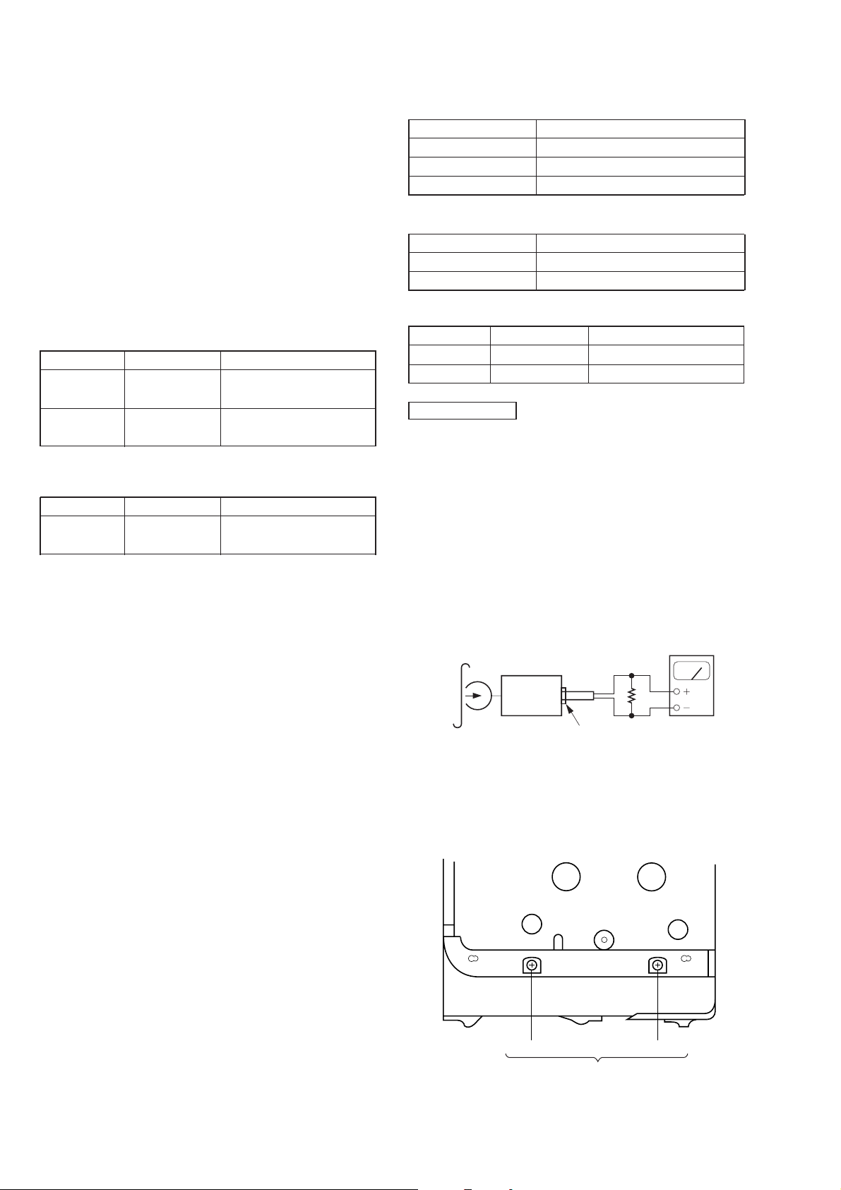
This set uses the photo reflector PH701 to detect the rotation of the gear. PH701 is on the main board and so remo v al of the main board does
not allow the set to detect the rotation of the gear. This makes motor control impossible which prevents normal operation.
When repairing the set as energized with the main board removed, proceed as follows:
• Service the Main Board
1. Short the BP701 (SERVICE) on the main board. (see the Fig. 1.)
2. Refer to the “SECTION3 DISASSEMBLY” (page 5) and open the main board.
3. Put a tape in the set.
4. Fixed at S703 (TAPE DET) on mode or connect the jumper wire between TP38 and GND (TP66).
5. Supply 3 V DC to the battery terminals.
6. Rotate the S701 (MODE SELECT) one turn by hand (mode sensor).
7. Press the desired operating switch (9 (, FF, etc.).
8. Check the mode on the liquid crystal panel. Use item 6 repeatedly to switch modes.
9. When finished with the job, disconnect the power and open (remove the short) the BP701 (SERVICE).
– MAIN BOARD (SIDE B) –
TP38
S701
(MODE SELECT)
BP701
(SERVICE)
S703
(TAPE DET)
SHORT
Fig. 1.
TP66
‘
terminal
’
terminal
– 3 –
SECTION 2
GENERAL
This section is extracted
from instruction manual.
– 4 –
SECTION 3
DISASSEMBLY
Note : This set can be disassemble according to the following sequence.
Set Panel (rear)
assy
Note : Follow the disassembly procedure in the numerical order given.
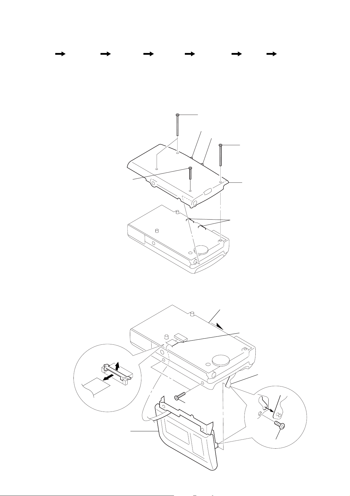
3-1. PANEL (REAR) ASSY
• When installing, position the knobs (V•O•R, MIC SENS) and the switches.
3
screw (M1.4x5.0), locking
Panel (lid)
assy
MD block
assy
Main board,
Frame Mode motor
complete
1
screws (B1.7x18) (G), tapping
knob (MIC SENS)
knob (V
•O •
R)
2
screw (B1.7x18) (G), tapping
4
panel (rear) assy
block
3-2. PANEL (LID) ASSY
b
a
switches
1
knob (EJECT)
2
CN102
5
lever (C holder) assy
6
panel (lid) assy
screws (M1.4),
3
toothed lock
– 5 –
4
screw
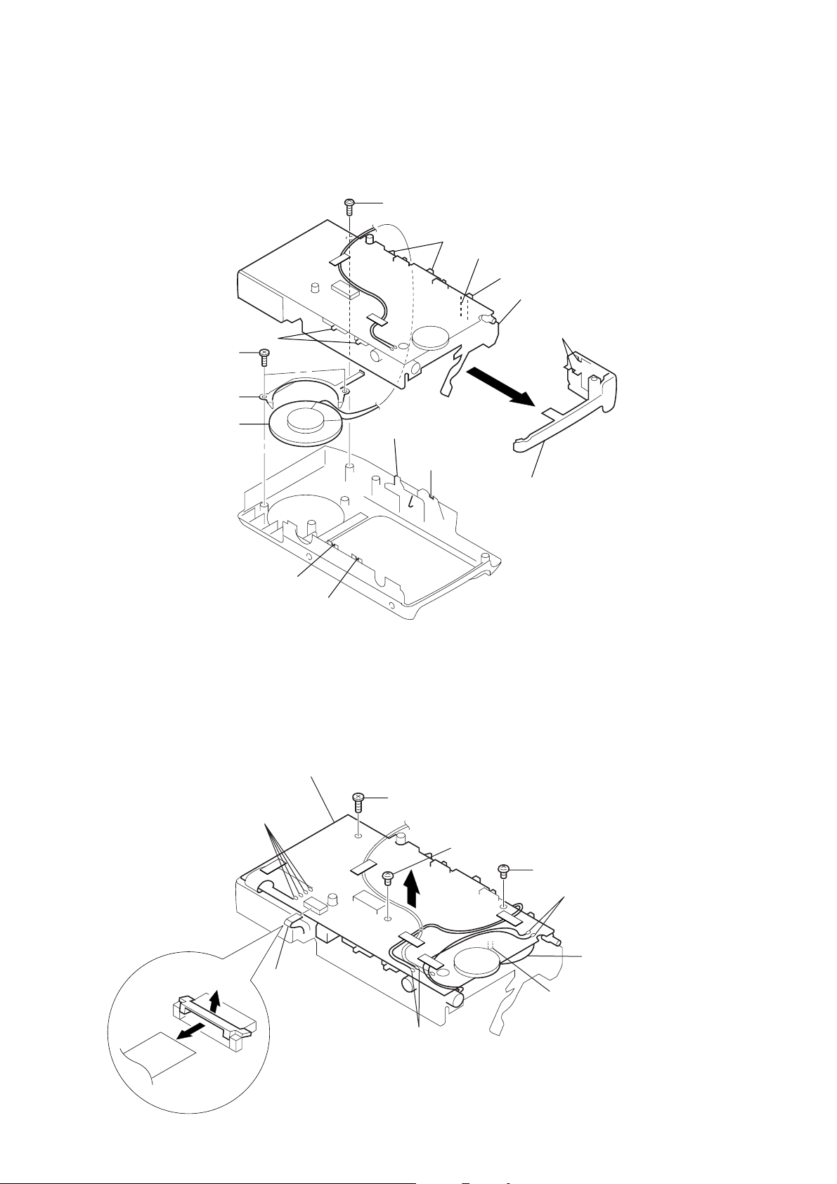
3-3. MD BLOCK ASSY
• When installing the MD block assy, position the knobs with the switches.
• When installing the microphone cabinet assy, align the knobs with the spring and switches.
1
screw (B1.7x4), tapping
switches
spring
4
screws (1.7x3), tapping
5
bracket (speaker)
6
speaker (2.8cm)
switches
knob
(HOLD EJECT)
knob
(FF/CUE•REW/REVIEW)
switch
2
MD block assy
knobs
(REC PAUSE/REC)
3
cabinet assy, microphone
knob (TAPE SPEED)
knob (FAST PB)
3-4. MAIN BOARD, COMPLETE
• When installing, position the cam gear with the switch.
8
3
unsolders
4
CN101
a
MAIN board, complete
7
screw (B1.7x4), tapping
6
screw, precision +P 1.4x1.6
5
screw, precision +P 1.4x1.6
1
switch
unsolders
gear, cam
b
– 6 –
2
unsolders
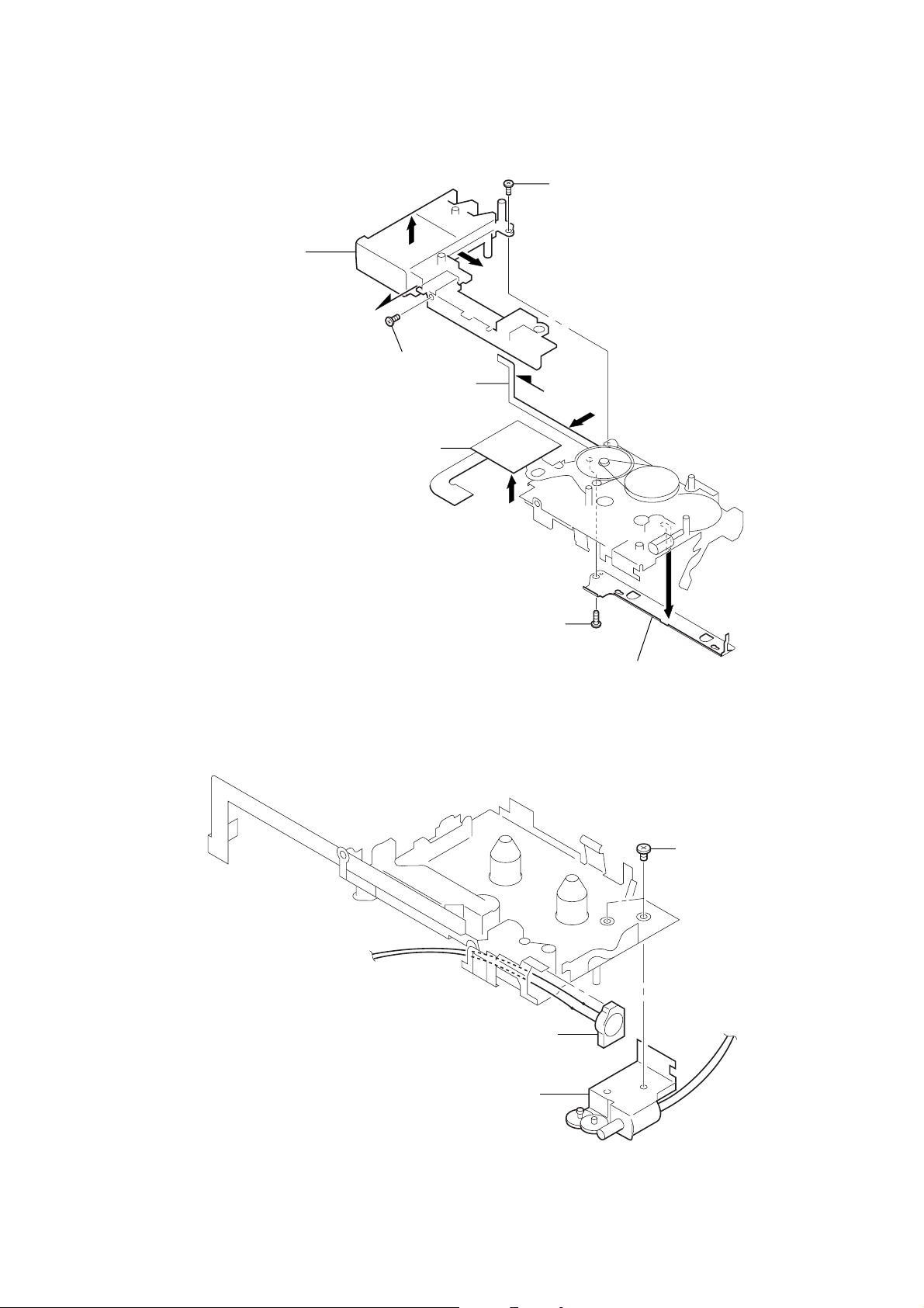
3-5. FRAME
• Be careful not to damage the flexible board.
• Remove from a to b to c.
7
frame
6
flexible board (head, magnetic)
5
absorbent, acoustic, reflection
a
b
3
screw
c
b
4
a
screw
c
3-6. MODE MOTOR BLOCK
1
screw (1.7x4), tapping (B)
3
microphone, electret condenser
2
cover (HD)
1
screws (M1.4)
2
mode motor block
– 7 –
SECTION 4
MECHANICAL ADJUSTMENTS
SECTION 5
ELECTRICAL ADJUSTMENTS
PRECAUTION
1. Before adjusting, clean the following parts with a piece of
cotton moistened with alcohol.
record/playback/erase head pinch roller
rubber belt capstan
2. Demagnetize the record/playback/erase head using a head
demagnetizer. (Do not bring the head demagnetizer close to the
erase head.)
3. Do not use a magnetized screwdriver for adjustments.
4. After adjusting, apply screw-locking compound to the adjusted
parts.
5. Unless specified otherwise, use a specified voltage (2.5 V DC)
to perform the adjustments.
Torque Measurement
TAPE SPEED switch : 2.4cm/s
Mode Torque Meter Meter Reading
FWD, REV
FF, REW CQ-201M
T ape Tension Measurement
TAPE SPEED switch : 2.4cm/s
Mode Torque Meter Meter Reading
FWD CQ-403M
CQ-103M
5 – 10 g • cm
(0.07 – 0.13 oz • inch)
more than 15 g • cm
(more than 0.209 oz • inch)
more than 15 g
(more than 0.53 oz)
Standard Input Level
Input terminal MIC (PLUG IN POWER) jack
Source impedance 300 Ω
Input level 0.77 mV (–60 dB)
Frequency 1 kHz
Standard Output Level
Output terminal EAR jack
Load impedance 10 kΩ
Output level 78 mV (–20 dB)
Test Tape
Type Signal User for
S-2-A030 3 kHz, –20 dB Azimuth Adjustment
WS-24 3 kHz, –10 dB Tape Speed Adjustment
0 dB = 0.775 V
PRECAUTION
• Switch and control position
VOL control : 5 (Mechanical center)
TAPE SPEED switch : 2.4cm/s
V•O•R switch : OFF
FAST PB switch : OFF
MIC SENS switch : H
Record/Playback/Erase Head Azimuth Adjustment
Procedure :
– FWD/REV playback –
test tape
S-2-A030
(3 kHz, –20 dB)
set
• Rotate the screw to adjust level meter reading to the maximum.
Note : Adjust to the maximum peak though there may be two or
three peaks.
Adjustment Location :
10 k
EAR jack (J102)
level meter
Ω
– 8 –
REV side
adjustment screws
FWD side
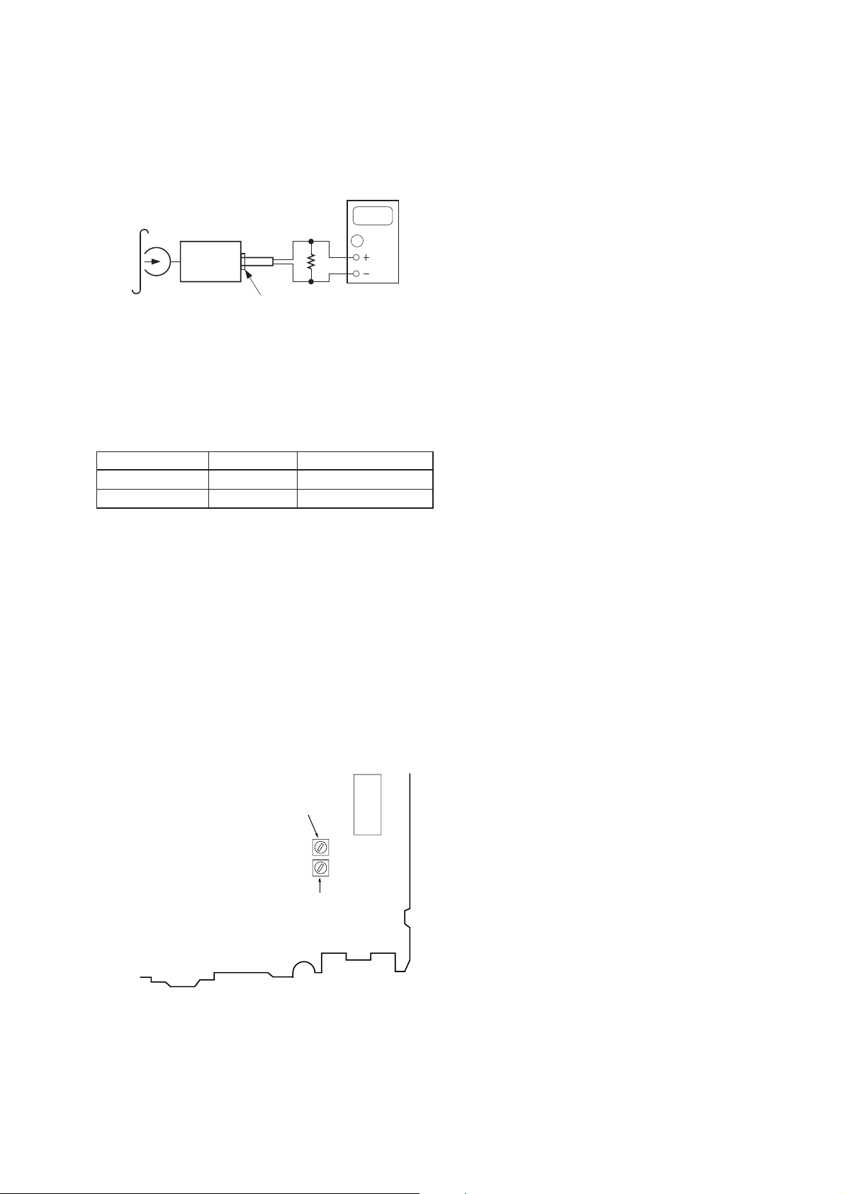
T ape Speed Adjustment
Procedure :
After adjusting the 2.4cm/s speed, adjust the 1.2cm/s speed.
– FWD/REV playback –
digital frequency
test tape
WS-24
(3 kHz, –10 dB)
10 k
set
EAR jack (J102)
counter
0000
Ω
1. Tape Speed : 2.4cm/s/FWD
Playback WS-24 (tape center part) and adjust RV601 so that
reading on the digital frequency counter becomes 3,000 Hz.
2. Tape Speed : 1.2cm/s/FWD
Playback WS-24 (tape center part) and adjust RV601 so that
reading on the digital frequency counter becomes 1,500 Hz.
Specification Value :
Adjustment part Tape speed Frequency counter
RV601 2.4cm/s 2,985 – 3,045 Hz
RV602 1.2cm/s 1,470 – 1,530 Hz
3. Tape Speed : 2.4cm/s/REV
Playback WS-24 (tape center part) in the REV state.
Check that digital frequency counter reading is within ± 2% of
reading of step 1.
4. Tape Speed : 1.2cm/s/REV
Playback WS-24 (tape center part) in the REV state.
Check that digital frequency counter reading is within ± 2% of
reading of step 2.
2.4cm/s : 60 Hz
1.2cm/s : 30 Hz
Adjustment Location : main board
– MAIN BOARD (SIDE B) –
IC601
RV602 1.2cm/s
RV601 2.4cm/s
– 9 –
 Loading...