

Sony M-800-V Service manual
M-800V/850V
SERVICE MANUAL
Ver 1.2 2004.08
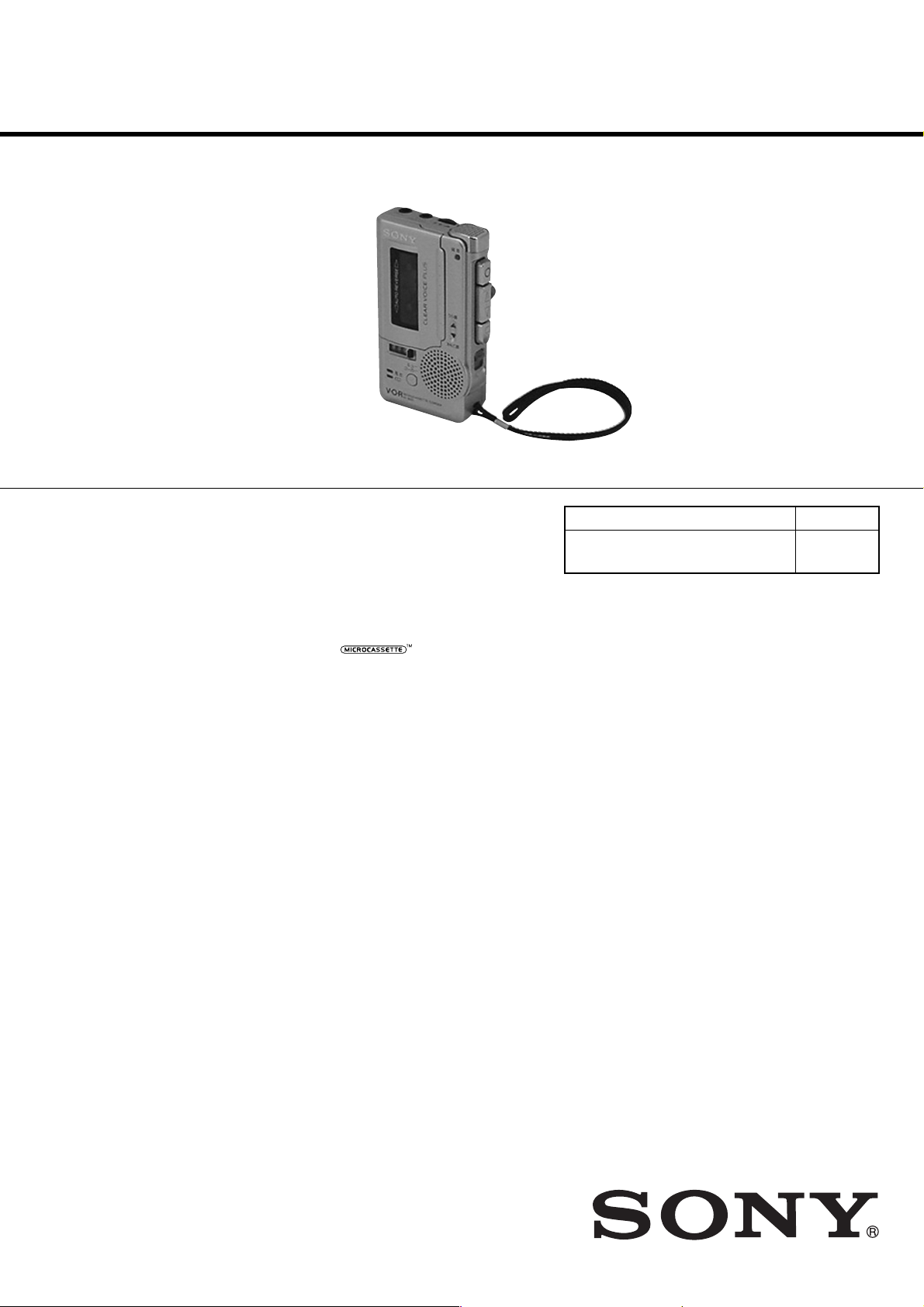
Photo : M-850V
SPECIFICATIONS
US Model
M-850V
AEP Model
M-850V
E Model
M-800V/850V
Chinese Model
East European Model
M-800V
Tourist Model
M-850V
Model Name Using Similar Mechanism
Tape Tr ansport Mechanism Type MZ-730V -99
M-730V/830V
MZ-800V-99
Tape
Recording system
2-track 1-channel monaural
Speaker
Approx. 2.8 cm (1
Tape speed
2.4 cm/s (
Frequency range
300 - 4 000 Hz (with TAPE SPEED switch at 2.4 cm/s)
Input
Microphone input jack (minijack/PLUG IN POWER)
sensitivity 0.21 mV for 3 kΩ or lower impedance microphone
Output
Earphone jack (minijack) for 8 - 300 Ω earphone
Power output (at 10% harmonic distortion)
250 mW
Power requirements
3 V DC batteries size AAA (R03) × 2/External DC 3V power sources
Dimensions (w/h/d)
Approx. 58.5 × 100 × 22.5 mm (2
and controls
Mass
Approx. 110 g (3.9 oz) (main unit only)
Supplied accessories
Microcassette tape MC-30 (1) (European model and world model of
M-850V only)
Batteries R03 (SB) (2) (European model and world model of M-850V
only)
Carrying pouch (1) (M-850V and European model of M-800V only)
Design and specifications are subject to change without notice.
(normal position type)
1
⁄8 in.) dia.
15
⁄16 ips), 1.2 cm/s (15⁄32 ips)
3
⁄8 × 4 × 29⁄32 in.) incl. projecting parts
9-873-543-03
2004H16-1
© 2004.08
Sony Corporation
Personal Audio Company
Published by Sony Engineering Corporation
MICROCASSETTE
-CORDER
TM
M-800V/850V
Ver 1.1 2004.01
TABLE OF CONTENTS
1. GENERAL ....................................................................3
2. DISASSEMBLY
2-1. Cassette Lid Assy····························································4
2-2. Cabinet (Rear) Sub Assy, Lid, Battery Case··················· 5
2-3. MAIN Board Section ······················································ 5
2-4. LED Board, Battery Holder ············································ 6
2-5. Mechanism Deck (MZ-730V-99)(MZ-800V-99)············6
2-6. Speaker (2.8cm) (SP901) ················································ 7
2-7. Microphone (MIC901)···················································· 7
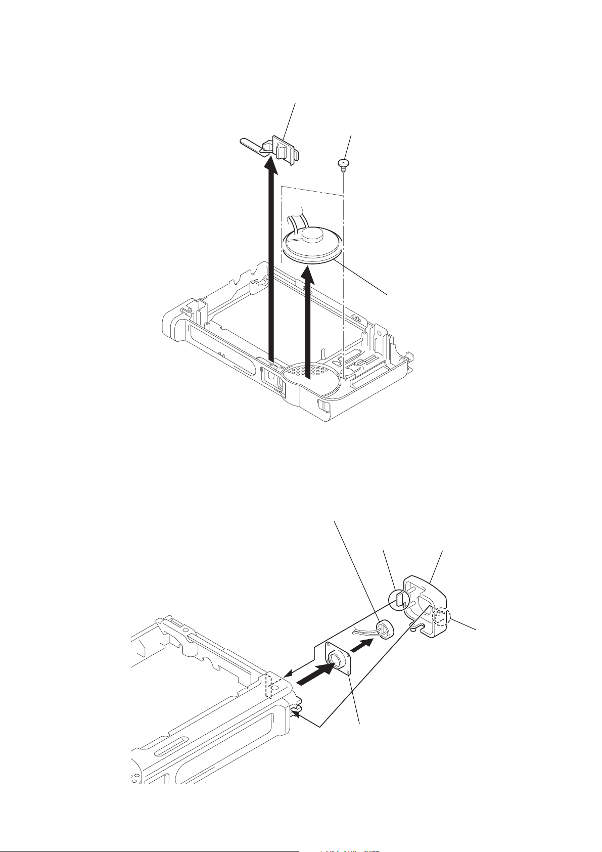
2-8. Ceramic Head (HRPE901,902)
and DC Motor (M901) ···················································· 8
3. MECHANICAL ADJUSTMENTS..............................9
4. ELECTRICAL ADJUSTMENTS ...............................9
5. DIAGRAMS
5-1. Block Diagram .............................................................. 11
5-2. Printed Wiring Board .................................................... 12
5-3. Schematic Diagram ....................................................... 13
5-4. Block Diagram .............................................................. 14
SERVICING NOTE
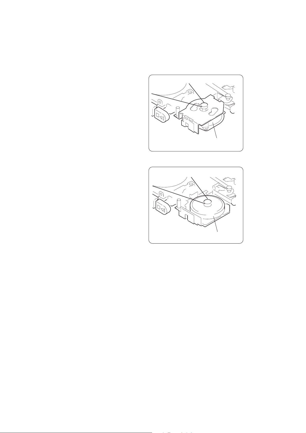
[How to recognize MZ-730V-99 and MZ-800V-99]
MZ-730V-99
DC motor (M901)
MZ-800V-99
6. EXPLODED VIEWS
6-1. Cabinet Section............................................................. 15
6-2. Mechanism Deck Section (1)
(MZ-730V-99)(MZ-800V-99)....................................... 16
6-3. Mechanism Deck Section (2)
(MZ-730V-99) .............................................................. 17
6-4. Mechanism Deck Section (2)
(MZ-800V-99) .............................................................. 18
7. ELECTRICAL PARTS LIST.....................................19
DC motor (M901)
Notes on Chip Component Replacement
• Never reuse a disconnected chip component.
• Notice that the minus side of a tantalum capacitor may be dam-
aged by heat.
Flexible Circuit Board Repairing
• Keep the temperature of the soldering iron around 270˚C during
repairing.
• Do not touch the soldering iron on the same conductor of the
circuit board (within 3 times).
• Be careful not to apply force on the conductor when soldering
or unsoldering.
2
SECTION 1
GENERAL
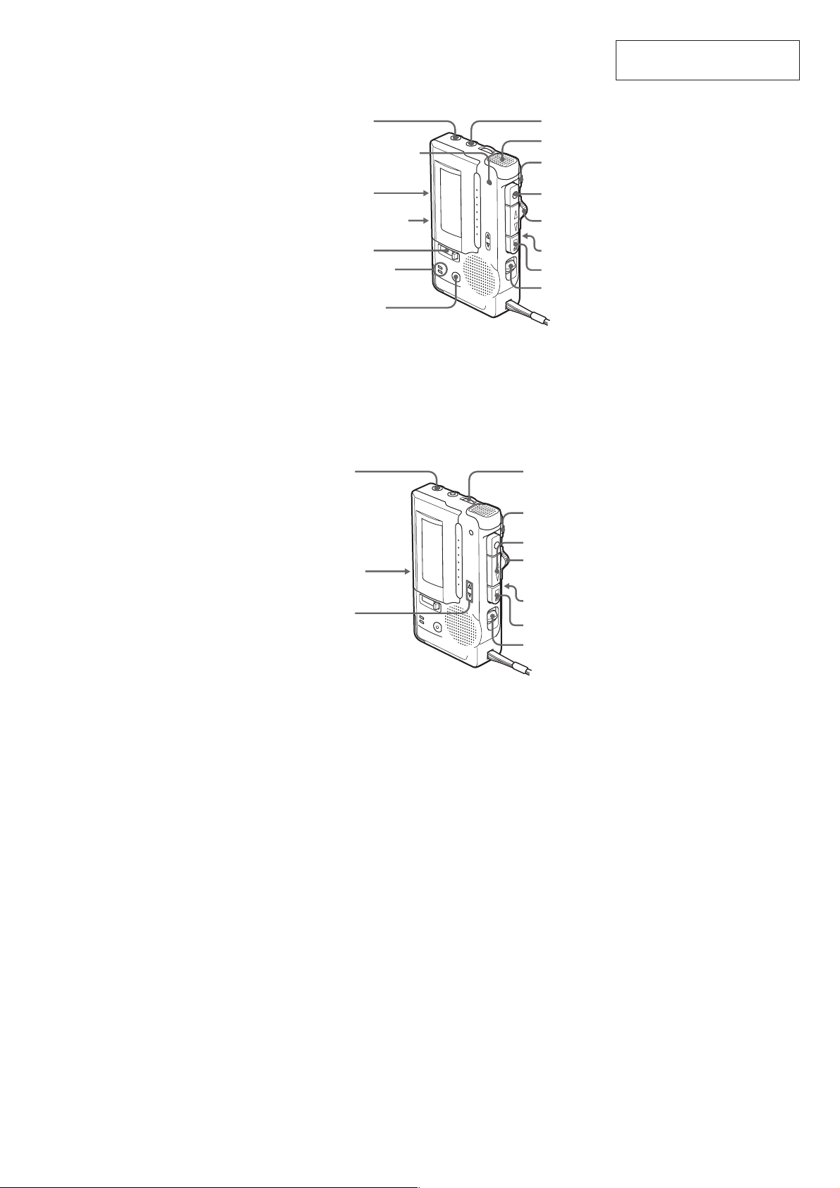
EAR
REC lamp (M-850V only)
REC/BATT lamp (M-800V only)
M-800V/850V
This section is extracted from
instruction manual.
MIC (PLUG
IN POWER)
Microphone
> PAUSE
VOR
FAST PB (M-850V only)
Tape counter
BATT/E lamp
(M-850V only)
CUE MARKER
(M-850V only)
EAR
FAST PB
(M-850V only)
Tape
direction
indicators
z
CUE/
REVIEW
TAPE SPEED
Tx
DIR
VOL
> PAUSE
nN
CUE/
REVIEW
TAPE SPEED
Tx
DIR
3
M-800V/850V
y
SECTION 2
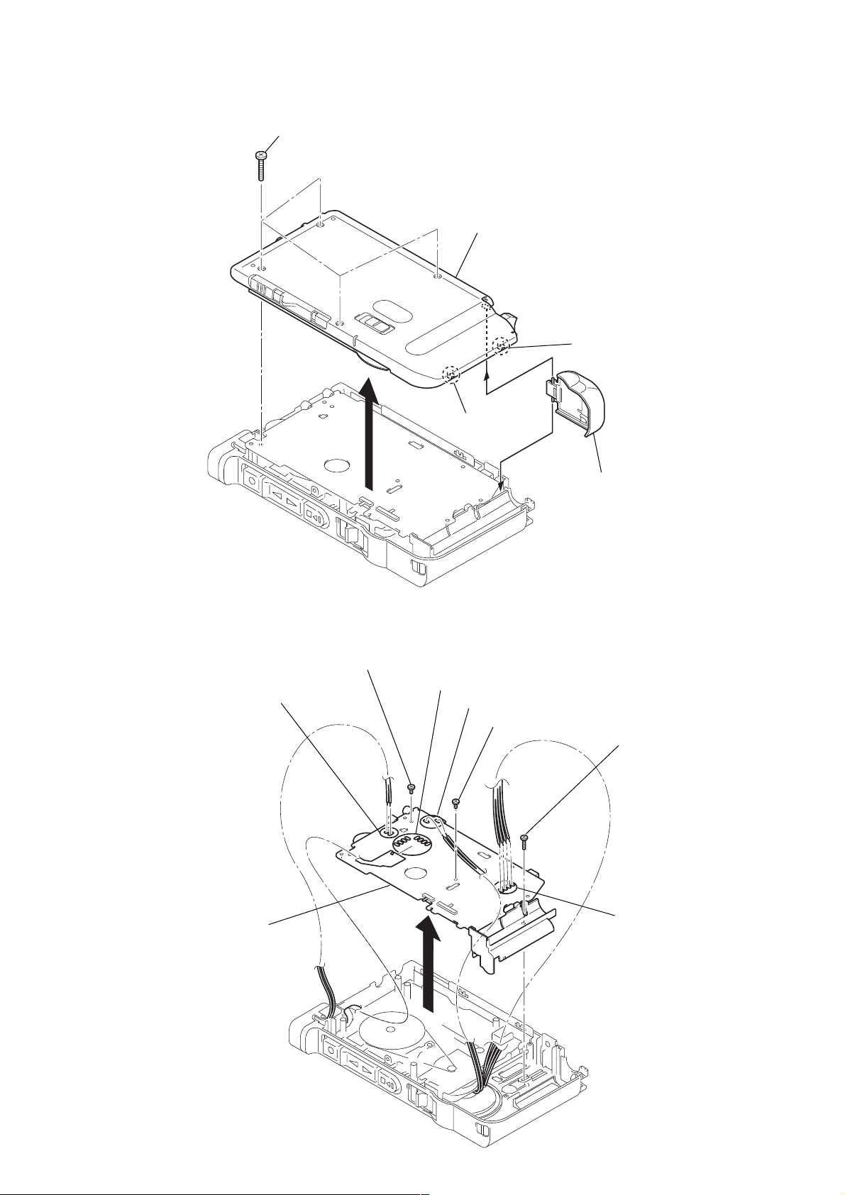
DISASSEMBLY
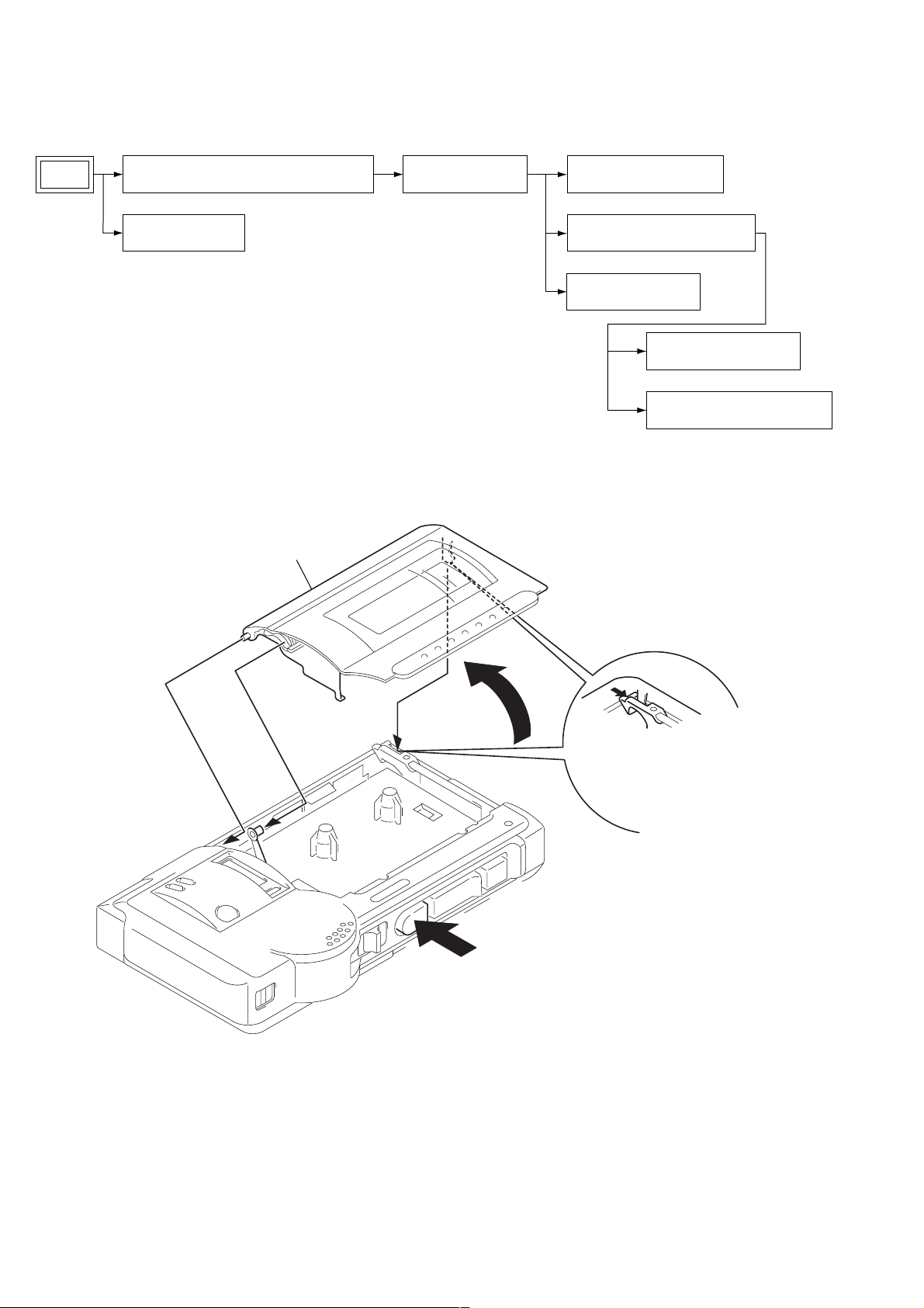
• The equipment can be removed using the following procedure.
Set
Note : Follow the disassembly procedure in the numerical order given.
Cabinet (rear) sub assy, Battery case lid
Cassette lid assy
MAIN board section
2-1. Cassette Lid Assy
6 cassette lid assy
LED board, Battery hoder
Mechanism deck (MZ-730V-99)
Microphone (MIC901)
Speaker (2.8cm) (SP901)
Ceramic head (HRPE901,902)
3
5
4
2
5 While push cassette lid ass
a bove remove
1 Open the cassette lid assy
by pushing button (STOP).
4
d
g
2-2. Cabinet (Rear) Sub Assy, Battery Case Lid
1 four screws (1.7x16)
M-800V/850V
5 cabinet (rear) sub assy
2 claw
3 claw
2-3. MAIN Board Section
1 Remove the soldering
(two portions)
4
6 battery case li
6 screw (IB lock)
2 Remove the soldering (eight portions)
3 Remove the soldering (two portions)
7 screw (IB lock)
5 screw (B1.7x9)
9 MAIN board
4 Remove the solderin
(four portions)
8
5
M-800V/850V
r
Ver 1.1 2004.01
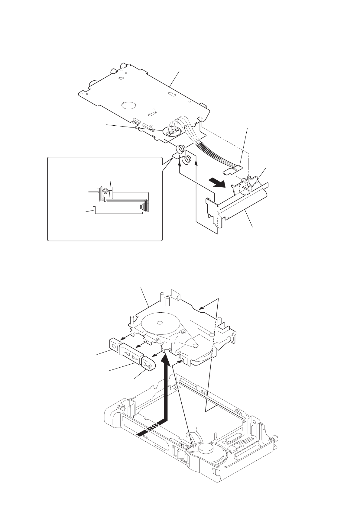
2-4. LED Board, Battery Holder
MAIN board
1 Remove the soldering
(four portions)
* Cautions when assembling
battery coil spring (-)
battery holder
On attaching the battery coil spring (-),
fit it to the groove on the battery holder.
2-5. Mechanism Deck (MZ-730V-99)(MZ-800V-99)
7
Mechanism deck (MZ-730V-99)(MZ-800V-99)
3
4
7 LED board
6 claw
2
5 battery holde
6
button (REC)
5
button (PLAY)
4
button (STOP)
3
1
6
2
)
2-6. Speaker (2.8cm) (SP901)
M-800V/850V
2 knob (DIR)
3 two screws (B2.0)
1
5 speaker (2.8cm) (SP901
4
2-7. Microphone (MIC901)
4 microphone (MIC901)
2 claw
5 microphone cushion
3 microphone case
1 claw
7
 Loading...