

Sony M-730-V, M-830-V Service manual
M-730V/830V
SERVICE MANUAL
Ver 1.1 1999. 01
Ver 1.1 2000. 01
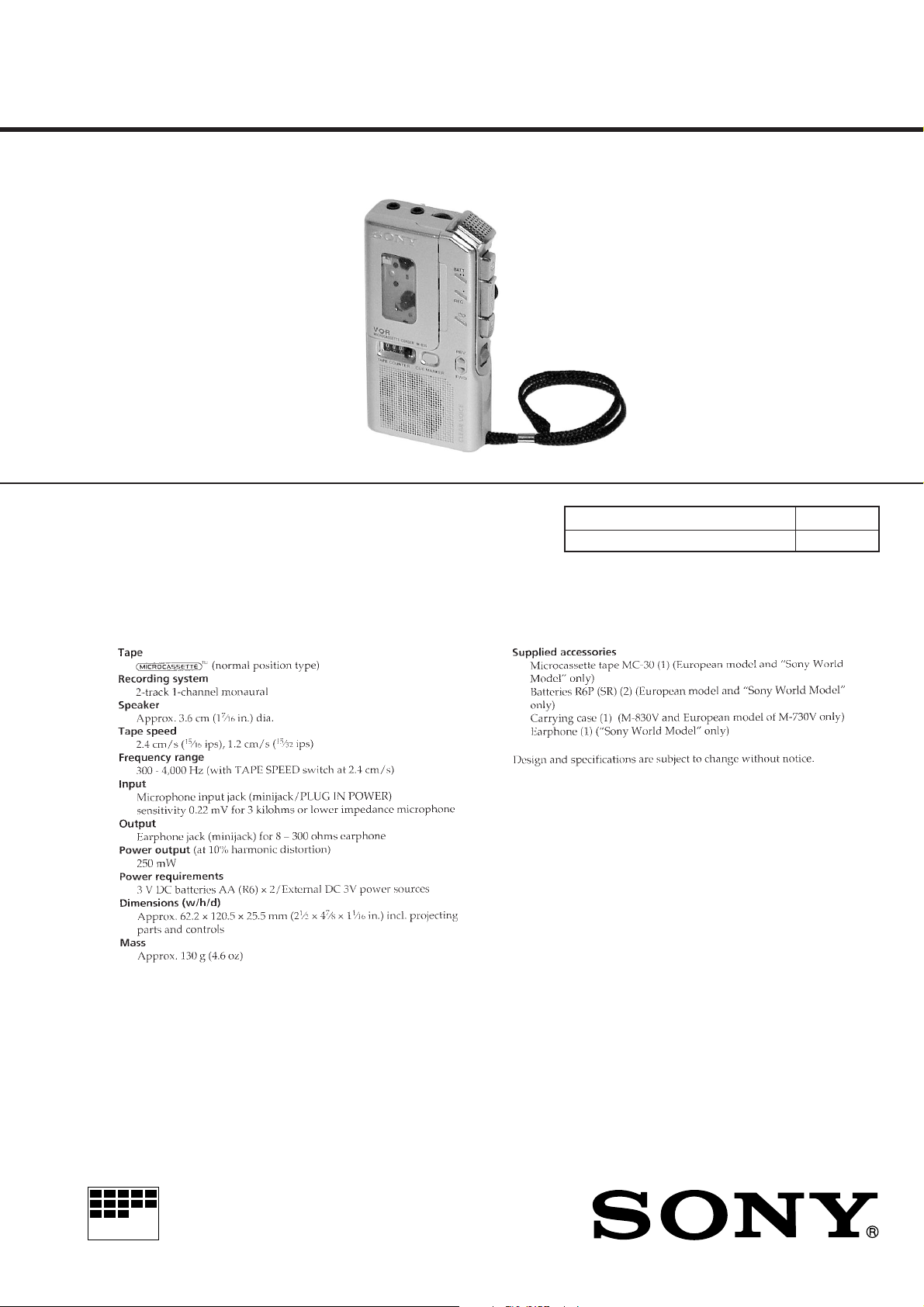
Photo : M-830V
SPECIFICATIONS
US Model
Canadian Model
AEP Model
E Model
M-730V/830V
Chinese Model
M-730V
Tourist Model
M-830V
Model Name Using Similar Mechanism NEW
T ape Transport Mechanism T ype MZ-730V -99
MICROFILM
– 1 –
MICROCASSETTE
TM
-CORDER

TABLE OF CONTENTS
1. GENERAL ....................................................................3
2. DISASSEMBLY
2-1. Lid Assy, Cassette ...............................................................4
2-2. Lid, Battery Case ................................................................ 4
2-3. Cabinet (Rear) Assy ............................................................ 5
2-4. Speaker Assy, Microphone ..................................................5
2-5. Main Board ......................................................................... 6
2-6. Mechanism Deck................................................................. 6
2-7. LED Unit............................................................................. 7
2-8. Head, Creamic (HRPE901, 902)......................................... 7
3. MECHANICAL ADJUSTMENTS..............................8
4. ELECTRICAL ADJUSTMENTS ...............................8
5. DIAGRAMS
5-1. Block Diagram .................................................................. 11
5-2. Printed Wiring Board ........................................................ 13
5-3. Schematic Diagram ........................................................... 15
6. EXPLODED VIEWS
6-1. Cabinet Section ................................................................. 17
6-2. Mechanism Deck Section (1) ............................................19
6-3. Mechanism Deck Section (2) ............................................20
7. ELECTRICAL PARTS LIST..................................... 21
Notes on Chip Component Replacement
• Never reuse a disconnected chip component.
• Notice that the minus side of a tantalum capacitor may be dam-
aged by heat.
Flexible Circuit Board Repairing
• Keep the temperature of the soldering iron around 270˚C during
repairing.
• Do not touch the soldering iron on the same conductor of the
circuit board (within 3 times).
• Be careful not to apply force on the conductor when soldering
or unsoldering.
– 2 –
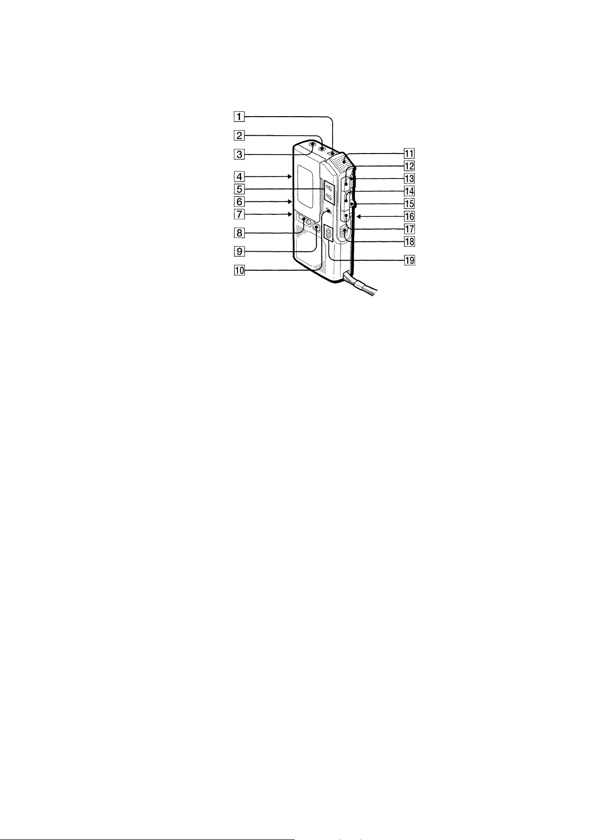
SECTION 1
GENERAL
1 VOL knob
2 MIC jack
3 EAR jack
4 VOR switch
5 REC/BATT lamp
6 FAST PB switch (M-830V ONLY)
7 DC IN 3V jack
8 TAPE COUNTER
9 CUE MARKER button (M-830V ONLY)
0 i(Battery) lamp (M-830V ONLY)
∑
!¡ Microphone
!™ r(REC) button
!£ C PAUSE knob
!¢ œ(Playback) button
!∞ CUE/REVIEW knob
!§ TAPE SPEED select knob
!¶ wp(Eject/Stop) button
!• DIR c knob
!ª FWD/REV
– 3 –
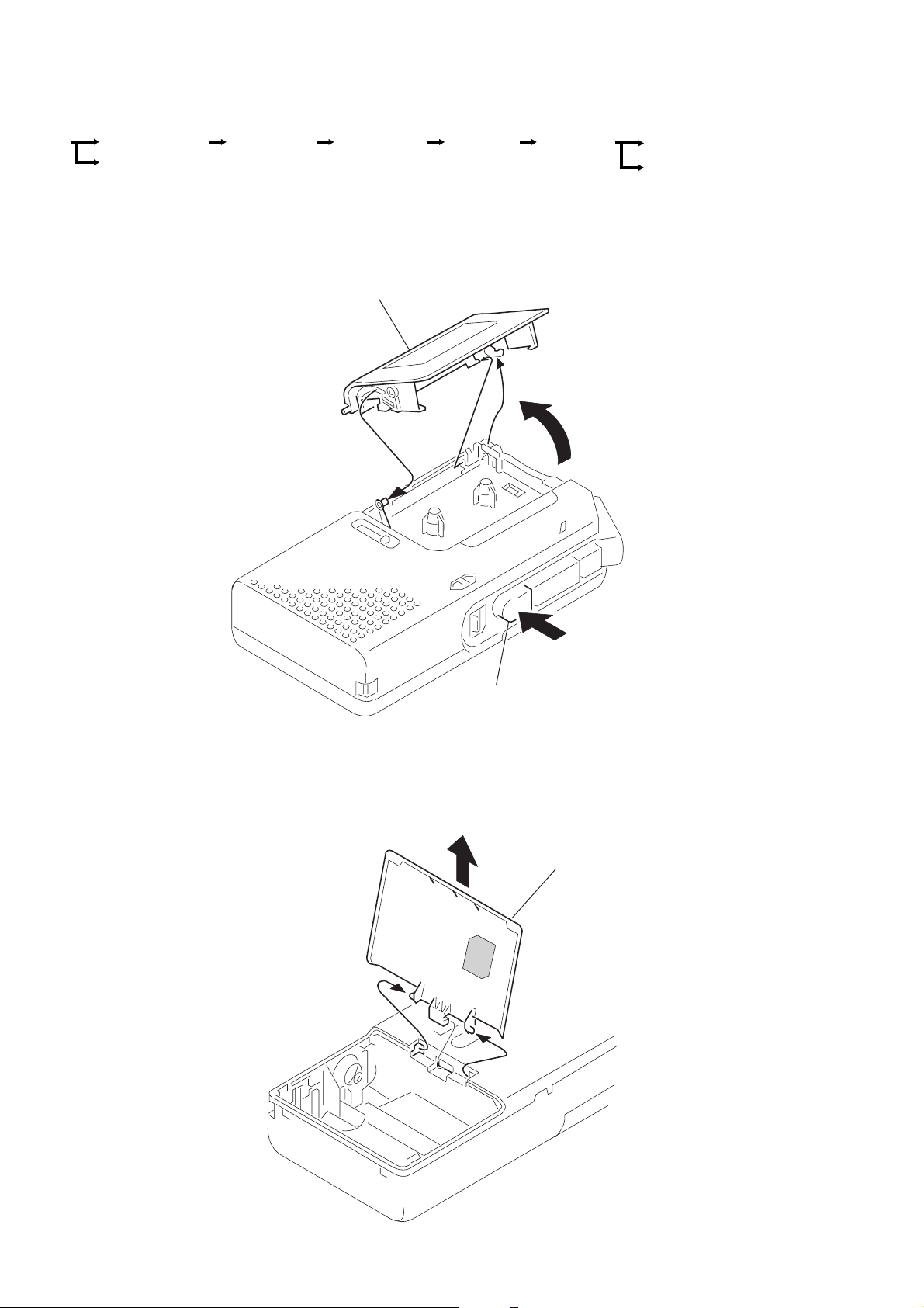
SECTION 2
DISASSEMBLY
• The equipment can be removed using the following procedure.
Set Lid assy, cassette
Lid, battery case
Note : Follow the disassembly procedure in the n umerical order given.
Cabinet (rear)
assy
2-1. LID ASSY, CASSETTE
Speaker assy,
Microphone
Lid assy, cassette
2
Main board
4
3
Mechanism
deck
5
Head, ceramic (HRPE901,902)
LED unit
2-2. LID, BATTERY CASE
1
wp
(Eject/Stop) button
2
1
1
Lid, battery case
– 4 –
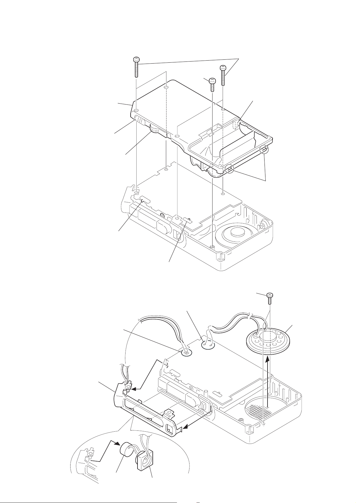
2-3. CABINET (REAR) ASSY
s
y
Note : When installing, fit the knobs and switches .
5
Cabinet
(rear) assy
Knob
(PAUSE)
Knob
(FR)
1
Screw
(B1.7
2
Four screws
(B1.7
×
5)
3
×
16)
Claw
4
Claw
Switch
(PAUSE)
2-4. SPEAKER ASSY, MICROPHONE
4
Unsolder the
2 places.
5
Microphone
unit
Switch
(TAPE SPEED)
1
Unsolder the
2 places.
2
T wo screws
×
(B2
2.5)
3
Speaker ass
6
8
Microphone
Mic cushion
7
– 5 –
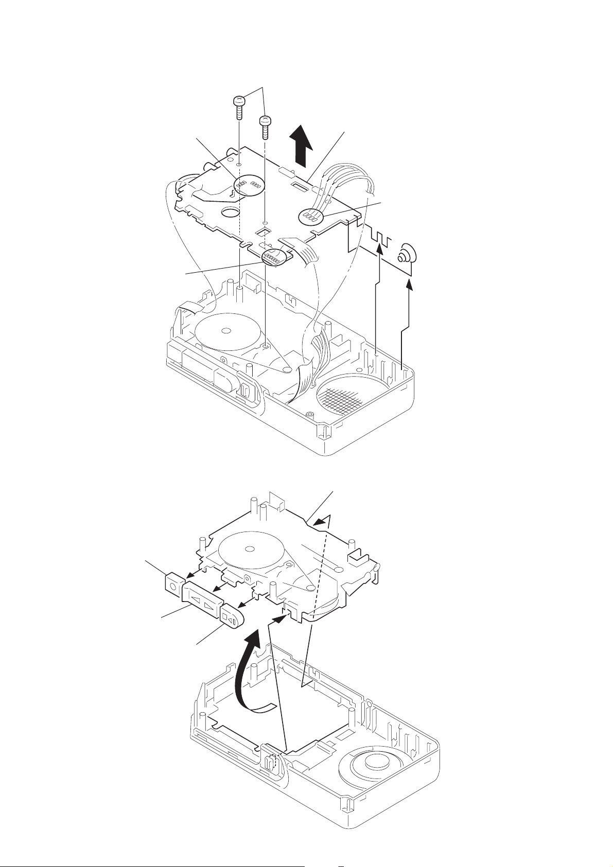
2-5. MAIN BOARD
1
Unsolder the 8 places.
2
Unsolder the
6 places.
4
T wo screws
6
Main board
3
4 places.
5
Unsolder the
6
2-6. MECHANISM DECK
Button
(REC)
Button
(PLAY)
Button
(EJECT/STOP)
3
1
4
Mechanism deck
2
– 6 –
 Loading...