

Sony M-675-V, M-673-V, M-670-V Service manual
M-670V/673V/675V
SERVICE MANUAL
Ver 1.1 2004. 03
Photo : M-670V
Model Name Using Similar Mechanism NEW
Tape Transport Mechanism Type MZ-670-99
US Model
M-673V/675V
AEP Model
M-673V
E Model
Chinese Model
Tourist Model
M-670V
SPECIFICATIONS
Tape
(MICROCASSETTE)
Recording system
2-track 1-channel monaural
Speaker
Approx. 2.8 cm (11⁄8 in.) dia.
Tape speed
2.4 cm/s (15⁄16 ips), 1.2 cm/s (15⁄32 ips)
Frequency range
300 - 4 000 Hz (with TAPE SPEED switch at 2.4 cm/s)
Input
Microphone input jack (minijack/monaural/PLUG IN POWER)
sensitivity 0.2 mV for 3 kΩ or lower impedance microphone
Output
Earphone jack (minijack/monaural) for 8 - 300 Ω earphone
Power output (at 10% harmonic distortion)
450 mW
Power requirements
3 V DC batteries size AAA (R03) x 2/External DC 3V power
sources
Dimensions (w/h/d) (incl. projecting parts and controls)
Approx. 54.8 x 106.8 x 21.5 mm (2 1⁄4 x 4 1⁄4 x 7⁄8 in.)
TM
(normal position type)
Mass (main unit only)
Approx. 92 g (3.3 oz)
Supplied accessories
AC power adaptor (1) (M-675V only), Battery charge adaptor
(1) (M-675V only), Rechargeable batteries NH-AAA, 1.2 V, typ.
800 mAh, Ni-MH (2) (M-675V only), Microcassette tape MC30 (1) (for the United States and Europe only), Alkaline batteries
LR03 (SG) (2) (M-673V, M-670V for the United States only),
Microphone (1) (M-673V only),Carrying pouch (1) (M670V:JEW/M-673V only), Battery carrying case (1) (M-675V
only)
Design and specifications are subject to change without notice.
•Abbreviation
JEW: Tour ist model
9-877-513-02
2004C02-1
© 2004.03
Sony Corporation
Personal Audio Company
Published by Sony Engineering Corporation
MICROCASSETTE
-CORDER
TM

M-670V/673V/675V
TABLE OF CONTENTS
Specifications ............................................................................ 1
1. GENERAL ................................................................... 3
2. DISASSEMBLY
2-1. Cassette Lid Assy ............................................................ 4
2-2. Cabinet (Rear) ................................................................. 4
2-3. Main Board...................................................................... 5
2-4. Mechanism Deck (MZ-670-99), LED Board ..................5
2-5. Ceramic Head (REC/PB/Erase) (HRPE901)................... 6
2-6. Motor (M901).................................................................. 6
3. ADJUSTMENTS........................................................ 7
4. DIAGRAMS
4-1. Block Diagrams ............................................................... 9
4-2. Printed Wiring Boards– Main Section (Side A)– ............ 10
Printed Wiring Boards– Main Section (Side B)– ............ 11
4-3. Schematic Diagram ......................................................... 12
4-4. IC Block Diagrams .......................................................... 13
5. EXPLODED VIEWS
5-1. Cabinet (Rear) Section .................................................... 14
5-2. Cabinet (Front) Section ................................................... 15
5-3. Mechanism Deck Section (MZ-670-99).......................... 16
Flexible Circuit Board Repairing
• Keep the temperature of the soldering iron around 270°C
during repairing.
• Do not touch the soldering iron on the same conductor of the
circuit board (within 3 times).
• Be careful not to apply force on the conductor when soldering
or unsoldering.
Notes on chip component replacement
• Never reuse a disconnected chip component.
• Notice that the minus side of a tantalum capacitor may be
damaged by heat.
6. ELECTRICAL PARTS LIST .................................. 17
2
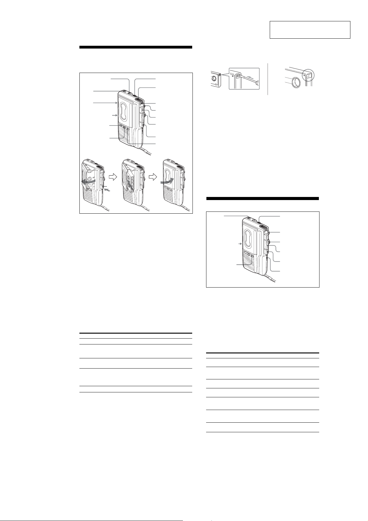
Recording
You can record right away with the built-in microphone.
Make sure that nothing is connected to the MIC jack.
MIC (PLUG IN
POWER)*
EAR
VOR
TAPE SPEED*
Tape counter
Tape counter
reset button
* The button/jack
has a tactile dot.
Tx
VOL*
Microphone
REC/BATT
> PAUSE
z
FF/CUE m•
M REW/REVIEW
Tx
E (Battery alert
LED)
SECTION 1
GENERAL
To prevent a cassette from being accidentally recorded
over
Break off and remove the cassette tabs. To reuse the cassette for
recording, cover the tab hole with adhesive tape.
Recording from Various Sound Sources
Notes
• When you are going to record something that you may not have an
opportunity to record again, test the unit first before you actually start
recording.
• When recording with an external microphone, the VOR system may not
work properly because of the difference in sensitivity.
Recording with an External Microphone
Connect a microphone firmly to the MIC jack.
M-673V : use the supplied microphone.
Other models : use a microphone of low impedance (less than 3
k ). When using a plug-in-power system microphone, the
power to the microphone is supplied from this unit.
Recording from another equipment
Connect another equipment firmly to the MIC jack using the
connecting cord (not supplied).
Set this unit to the recording mode and another equipment to
the playback mode.
M-670V/673V/675V
This section is extracted from
instruction manual.
1 Press the reset button of the tape counter.
2 Press Tx and insert a standard microcassette with the side
to start recording facing the lid.
3 Select the desired tape speed.
2.4 cm for optimum sound (recommended for normal use):
A 30-minute recording can be made using both sides of the
MC-30 microcassette (supplied for the United States and
Europe only). There is a tactile dot on this side.
1.2 cm for longer recording time: A 60-minute recording can
be made using both sides of the MC-30 microcassette
(supplied for the United States and Europe only).
4 Set VOR to OFF.
If you set VOR to ON, the unit automatically starts
recording the sound and pauses when there is no sound
(you can save tapes and batteries).
When the sound is not loud enough, set it to OFF, or the unit
may not start recording.
5 Press z. n is pressed simultaneously and recording starts.
While the tape runs, the REC/BATT lamp lights and flashes
depending on the strength of the sound.
Recording level is fixed.
At the end of the tape, recording stops and the unit turns off
automatically (Automatic shut-off mechanism).
To Press or slide
Stop recording Tx
Pause recording
Start recording during z during playback (the unit enters the
playback recording mode)
Review the portion just Push up FF/CUE m•MREW/REVIEW
recorded toward MREW/REVIEW during the
Take out a cassette Tx
* >PAUSE will also be automatically released when Tx is pressed
(stop-pause-release function).
Note
Select the 2.4 cm tape speed for recording, if you play back the recorded
tape with another unit. Otherwise, the sound quality may be changed.
Notes on VOR (Voice Operated Recording)
• The VOR system is affected by the environmental recording conditions.
When you use the system in a noisy place, the unit will stay in the
recording mode. If the sound is too soft, on the contrary, the unit will
not start recording. If you cannot get the results you want, set it to OFF.
• The VOR system may not record the beginning of the sound you want
to record because it starts recording only after it catches the sound. For
an important recording, set it to OFF.
To monitor the sound
Connect an earphone (not supplied) firmly to the EAR jack. The
monitor volume cannot be adjusted by VOL.
Slide >PAUSE in the direction of the arrow.
To release pause recording, release
>
PAUSE*.
recording. Release the button at the point to
start playback.
Playing a Tape
EAR
TAPE SPEED*
E (Battery
alert LED)
1 Insert a cassette with the side to start playing facing the lid.
2 Select the tape speed to the same speed as that used for
recording.
3 Press n.
4 Turn VOL to adjust the volume. There is a tactile dot beside
VOL on to show the direction to turn up the volume.
At the end of the tape, playback stops and the unit turns off
automatically (Automatic shut-off mechanism). After the tape
has been wound or rewound, be sure to press Tx.
If you plug in headphones (not supplied) to the EAR jack, you
will get monaural output from both left and right channels.
To Press or slide
Stop playback/stop fast Tx
forward or rewind
Pause playback Slide > PAUSE in the direction of the
Fast forward** (FF) Slide FF/CUE m• M REW/REVIEW
Rewind** (REW) Slide FF/CUE m• M REW/REVIEW
Search forward during Keep FF/CUE m• M REW/REVIEW
playback (CUE) pushed toward FF/CUE m during playback
Search backward during Keep FF/CUE m• M REW/REVIEW
playback (REVIEW) pushed toward M REW/REVIEW during
Start recording during z
playback
* >PAUSE will also be automatically released when Tx is pressed
(stop-pause-release function).
**If you leave the unit after the tape has been wound or rewound, the
batteries will be consumed rapidly. Be sure to press Tx.
Note
If the tape is completely rewound while searching backward during
playback (REVIEW), the FF/CUE m• M REW/REVIEW switch may
not return to the center position when you release the switch. In this case,
push back the switch to the center to start playback.
To increase the playback speed
Slide the FAST PB . switch in the direction of the arrow. The
playback speed will be increased.
To return to the original speed, slide the FAST PB . switch to
the original position.
arrow. REC/BATT lamp goes off.
To release pause
toward FF/CUE m during stop.
toward M REW/REVIEW during stop.
and release it at the point you want.
playback and release it at the point you want.
VOL*
>PAUSE
FF/CUE m•
M REW/REVIEW
n*
Tx
FAST PB .
playback
, release >PAUSE*.
* The button has a
tactile dot.
3
M-670V/673V/675V
y
)
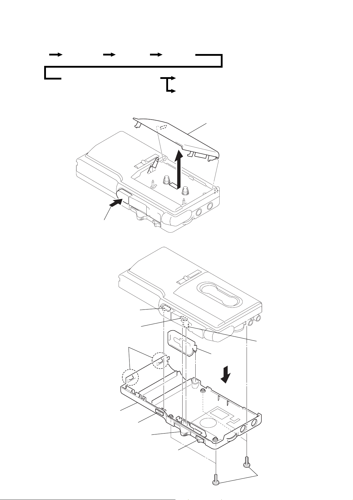
• This set can be disassembled in the order shown below.
Cassette lid assy Set Cabinet (rear) MAIN board
SECTION 2
DISASSEMBLY
Mechanism deck (MZ-670-99), LED board
Note: Follow the disassembly procedure in the numerical order given.
2-1. CASSETTE LID ASSY
1
eject
3-2. CABINET (REAR)
3
Ceramic head (HRPE901)
Motor (M901)
5
cassette lid ass
4
2
5
cabinet (front)
• CAUTIONS DURING ASSEMBLY
Align these switches and knobs
S301 t Knob (pause)
S602 t Knob (fast PB)
Lever (F/R) t Knob (FR)
S602
S301
2
claws
knob (fast PB)
knob (FR)
knob (pause)
4
battery lid
3
lever (F/R)
1
four screws (B1.7 x 14
4
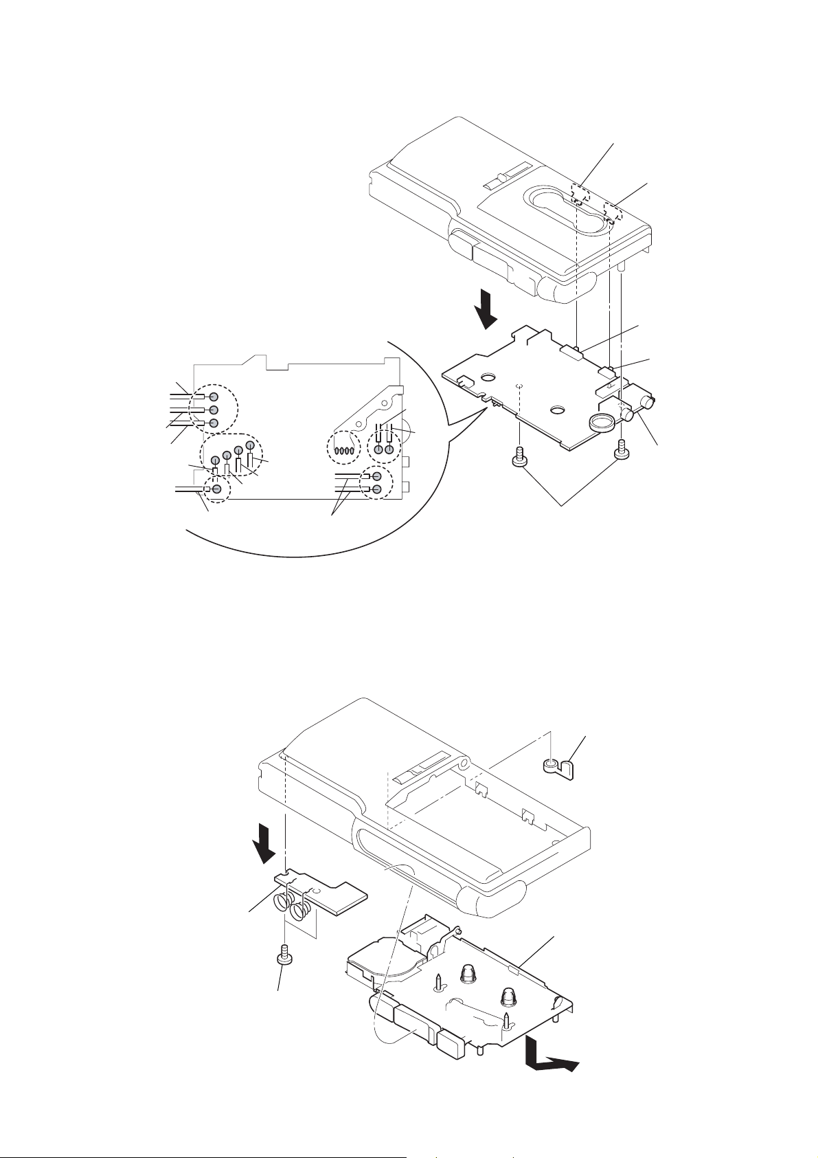
2-3. MAIN BOARD
• CAUTIONS DURING ASSEMBLY
Align these switches and knobs
S501 t Knob (tape speed) (VOR)
S601 t Knob (tape speed) (tape speed)
1
Remove solder (sixteen places)
BLK
RED
WHT
RED
BLK
BRN
WHT
WHT
BLK
RED
BLK
3
M-670V/673V/675V
knob (tape speed) (tape speed)
knob (tape speed) (VOR)
S601
S501
MAIN board
2
two screws
2-4. MECHANISM DECK (MZ-670-99), LED BOARD
4
6
LED board
3
two screws
5
window (BATT LED)
mechanism deck
2
(MZ-670-99)
1
5
M-670V/673V/675V
y
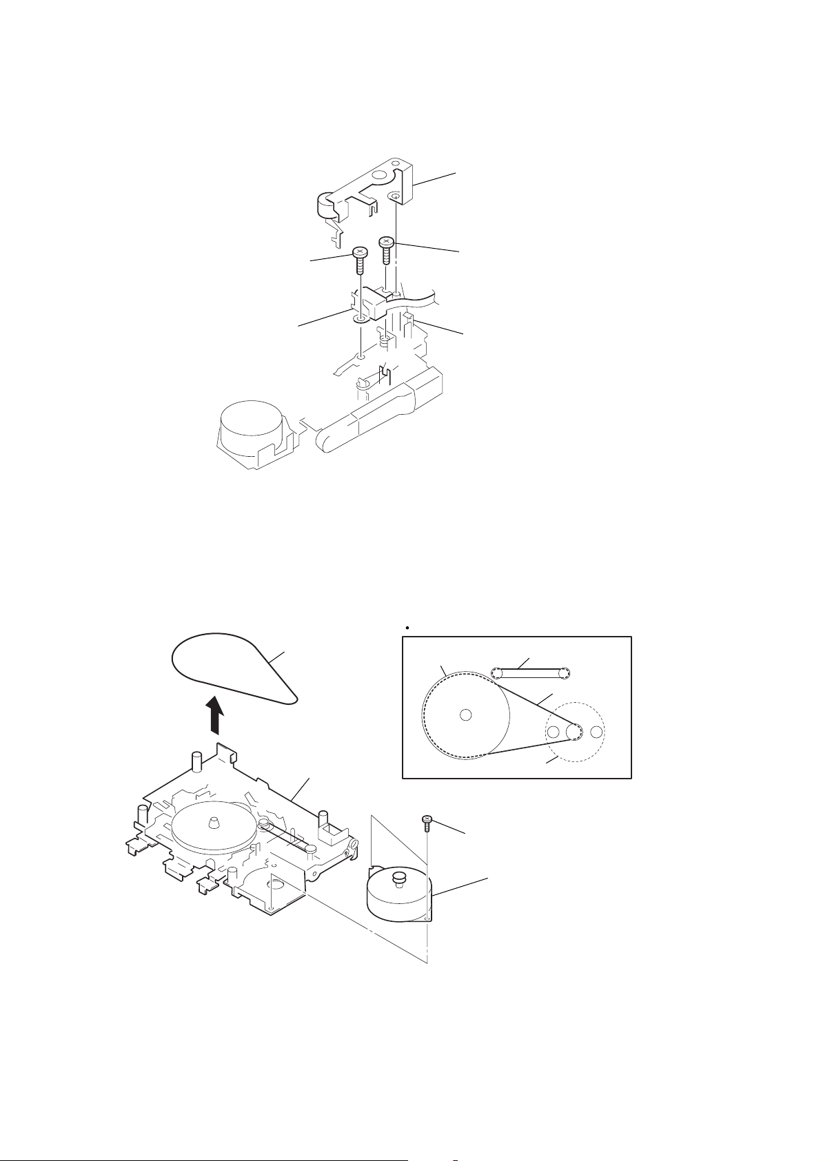
2-5. CERAMIC HEAD (REC/PB/ERASE) (HRPE901)
4
M1.4, special head
5
ceramic head
(HRPE901)
2
arm (pinch roller) ass
3
M1.4, special head
1
claw
2-6. MOTOR (M901)
1
How to apply the belts
belt (flywheel)
flywheel assy
mechanism deck
belt (counter, tape)
2
two screws
3
motor (M901)
belt (flywheel)
M901
6
 Loading...