

Page 1
4-548-214-11(1)
2015-09
LCD Monitor
Instructions for Use
Before operating the unit, please read this manual thoroughly
and retain it for future reference.
LMD-X310MD
LMD-X550MD
© 2015 Sony Corporation
Page 2
Owner’s Record
The model and serial numbers are located at the rear.
Record these numbers in the spaces provided below.
Refer to these numbers whenever you call upon your
Sony dealer regarding this product.
Model No.
Serial No.
Indications for Use/Intended Use
The LCD Monitor is intended to provide 4K 2D color
video displays of images from endoscopic/laparoscopic
camera systems and other compatible medical imaging
systems.
The LCD Monitor is a widescreen, high-definition,
medical grade monitor for real-time use during
minimally invasive surgical procedures and is suitable
for in hospital operating rooms, surgical centers, clinics,
doctors’ offices and similar medical environments.
WARNING
To reduce the risk of fire or electric shock, do not
expose this apparatus to rain or moisture.
To avoid electrical shock, do not open the cabinet.
Refer servicing to qualified personnel only.
No modification of this equipment is allowed.
LMD-X550MD only
THIS APPARATUS MUST BE EARTHED.
Symbols on the products
This symbol indicates the equipotential
terminal which brings the various parts of a
system to the same potential.
Safety sign
Follow the warnings in the Instructions for
Use for parts of the unit on which this mark
appears.
NOTE Background color: Blue
Symbol: White
Consult the Instructions for Use
Follow the directions in the Instructions for
Use for parts of the unit on which this mark
appears.
This symbol indicates the manufacturer,
and appears next to the manufacturer’s
name and address.
This symbol indicates the European
Community representative, and appears
next to the European Community
representative’s name and address.
For the customers in the U.S.A.
This equipment has been tested and found to comply
with the limits for a Class A digital device, pursuant to
part 15 of the FCC Rules. These limits are designed to
provide reasonable protection against harmful
interference when the equipment is operated in a
commercial environment. This equipment generates,
uses and can radiate radio frequency energy and, if not
installed and used in accordance with the instruction
manual, may cause harmful interference to radio
communications. Operation of this equipment in a
residential area is likely to cause harmful interference in
which case the user will be required to correct the
interference at his own expense.
You are cautioned that any changes or modifications not
expressly approved in this manual could void your
authority to operate this equipment.
All interface cables used to connect peripherals must be
shielded in order to comply with the limits for a digital
device pursuant to Subpart B of part 15 of FCC Rules.
This device complies with part 15 of the FCC Rules.
Operation is subject to the following two conditions:
(1) This device may not cause harmful interference, and
(2) this device must accept any interference received,
including interference that may cause undesired
operation.
2
Page 3
For the customers in Canada
CAN ICES-3 (A)/NMB-3(A)
3. The leakage current could increase when connected
to other equipment.
This unit has been certified according to Standard CAN/
CSA-C22.2 No.60601-1.
4. For this particular equipment, all accessory
equipment connected as noted above, must be
connected to mains via an additional isolation
Important safeguards/notices for use in the
medical environments
1. All the equipments connected to this unit shall be
transformer conforming with the construction
requirements of IEC60601-1 and providing at least
Basic Insulation.
certified according to Standard IEC60601-1,
IEC60950-1, IEC60065 or other IEC/ISO Standards
applicable to the equipments.
5. This equipment generates, uses, and can radiate
radio frequency energy. If it is not installed and used
in accordance with the instruction manual, it may
2. Furthermore all configurations shall comply with the
system standard IEC60601-1-1. Everybody who
connects additional equipment to the signal input
part or signal output part configures a medical
system, and is therefore, responsible that the system
complies with the requirements of the system
cause interference to other equipment. If this unit
causes interference (which can be determined by
unplugging the power cord from the unit), try these
measures: Relocate the unit with respect to the
susceptible equipment. Plug this unit and the
susceptible equipment into different branch circuit.
standard IEC60601-1-1.
If in doubt, consult the qualified service personnel.
Consult your dealer. (According to standard IEC606011-2 and CISPR11, Class B, Group 1)
Important EMC notices for use in the medical environments
The LMD-X310MD/X550MD needs special precautions regarding EMC and needs to be installed and put into service
according to the EMC information provided in the instructions for use.
The portable and mobile RF communications equipment such as cellular phones can affect the LMD-X310MD/
X550MD.
Warning
The use of accessories and cables other than those specified, with the exception of replacement parts sold by Sony
Corporation, may result in increased emissions or decreased immunity of the LMD-X310MD/X550MD.
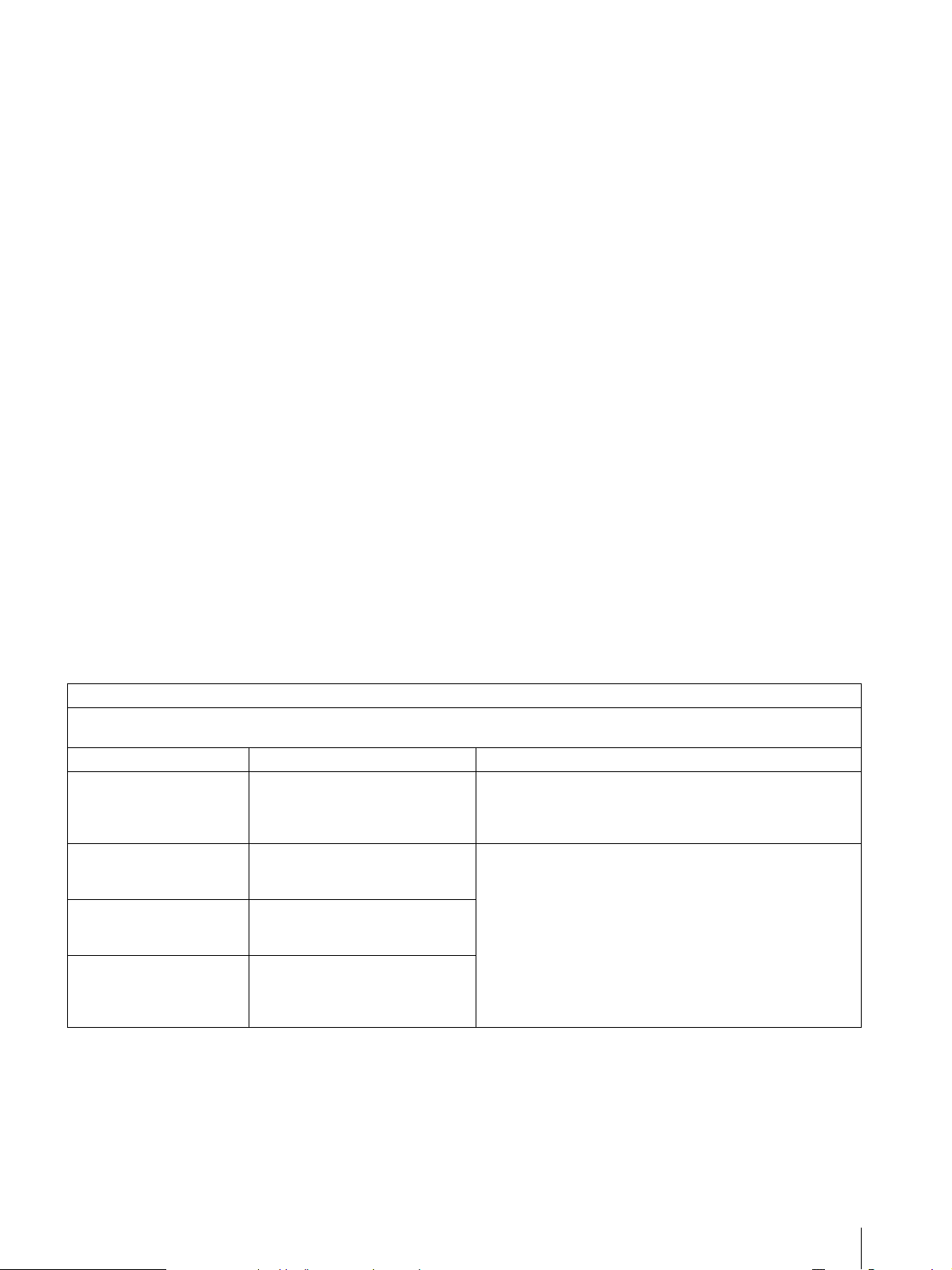
Guidance and manufacturer’s declaration-electromagnetic emissions
The LMD-X310MD/X550MD is intended for use in the electromagnetic environment specified below.
The customer or the user of the LMD-X310MD/X550MD should assure that it is used in such an environment.
Emission test Compliance Electromagnetic environment-guidance
RF emissions
CISPR 11
RF emissions
CISPR 11
Harmonic emissions
IEC 61000-3-2
Voltage f l u c tu a t i o n s /
flicker emissions
IEC 61000-3-3
Group 1
Class B
Not applicable (LMD-X310MD)
Class D (LMD-X550MD)
Not applicable (LMD-X310MD)
Complies (LMD-X550MD)
The LMD-X310MD/X550MD uses RF energy only for its
internal function. Therefore, its RF emissions are very low and
are not likely to cause any interference in nearby electronic
equipment.
The LMD-X310MD/X550MD is suitable for use in all
establishments, including domestic establishments and those
directly connected to the public low-voltage power supply
network that supplies buildings used for domestic purposes.
Warning
If the LMD-X310MD/X550MD should be used adjacent to or stacked with other equipment, it should be observed to
verify normal operation in the configuration in which it will be used.
3
Page 4
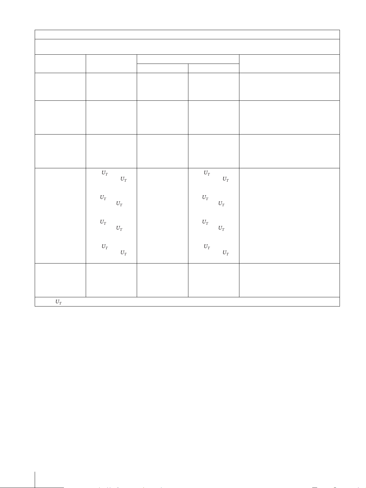
Guidance and manufacturer’s declaration - electromagnetic immunity
The LMD-X310MD/X550MD is intended for use in the electromagnetic environment specified below. The customer or the user of the
LMD-X310MD/X550MD should assure that it is used in such as environment.
Immunity test IEC 60601 test level
Electrostatic
discharge (ESD)
IEC 61000-4-2
Electrical fast
transient/burst
IEC 61000-4-4
Surge
IEC 61000-4-5
Voltage dips, short
interruptions and
voltage variations
on power supply
input lines
IEC 61000-4-11
±6 kV contact
±8 kV air
±2 kV for power
supply lines
±1 kV for input/
output lines
±1 kV line(s) to
line(s)
±2 kV line(s) to
earth
< 5%
(> 95% dip in )
for 0.5 cycle
40%
(60% dip in )
for 5 cycles
70%
(30% dip in )
for 25 cycles
LMD-X310MD LMD-X550MD
±6 kV contact
±8 kV air
±1 kV for input/
output lines
Not applicable ±1 kV differential
Not applicable < 5%
Compliance level
±6 kV contact
±8 kV air
±2 kV for power
supply lines
±1 kV for input/
output lines
mode
±2 kV common
mode
(> 95% dip in )
for 0.5 cycle
40%
(60% dip in )
for 5 cycles
70%
(30% dip in )
for 25 cycles
Electromagnetic environment-guidance
Floors should be wood, concrete or
ceramic tile. If floors are covered with
synthetic material, the relative humidity
should be at least 30%.
Mains power quality should be that of a
typical commercial or hospital
environment.
Mains power quality should be that of a
typical commercial or hospital
environment.
Mains power quality should be that of a
typical commercial or hospital
environment. If the user of the LMDX310MD/X550MD requires continued
operation during power mains
interruptions, it is recommended that the
LMD-X310MD/X550MD be powered
from an uninterruptible power supply or a
battery.
< 5%
(> 95% dip in )
for 5 sec
Power frequency
(50/60 Hz)
magnetic field
IEC 61000-4-8
NOTE: is the a.c. mains voltage prior to application of the test level.
3 A/m 3 A/m 3 A/m Power frequency magnetic fields should
< 5%
(> 95% dip in )
for 5 sec
be at levels characteristic of a typical
location in a typical commercial or
hospital environment.
4
Page 5
Guidance and manufacturer’s declaration - electromagnetic immunity
The LMD-X310MD/X550MD is intended for use in the electromagnetic environment specified below. The customer or the user of the
LMD-X310MD/X550MD should assure that it is used in such as environment.
Immunity test IEC 60601 test level Compliance level Electromagnetic environment-guidance
Portable and mobile RF communications equipment should be
used no closer to any part of the LMD-X310MD/X550MD,
including cables, than the recommended separation distance
calculated from the equation appliance to the frequency of the
transmitter.
Recommended separation distance
Conducted RF
IEC 61000-4-6
Radiated RF
IEC 61000-4-3
NOTE 1: At 80 MHz and 800 MHz, the higher frequency range applies.
NOTE 2: These guidelines may not apply in all situations. Electromagnetic propagation is affected by absorption and reflection from
structures, objects and people.
a Field strengths from fixed transmitters, such as base stations for radio (cellular/cordless) telephones and land mobile radios, amateur
radio, AM and FM radio broadcast and TV broadcast cannot be predicted theoretically with accuracy. To assess the electromagnetic
environment due to fixed RF transmitters, an electromagnetic site survey should be considered. If the measured field strength in the
location in which the LMD-X310MD/X550MD is used exceeds the applicable RF compliance level above, the LMD-X310MD/
X550MD should be observed to verify normal operation. If abnormal performance is observed, additional measures may be
necessary, such as reorienting or relocating the LMD-X310MD/X550MD.
3 Vrms
150 kHz to 80 MHz
3 V/m
80 MHz to 2.5 GHz
3 Vrms
3 V/m
d = 1.2
d = 1.2 80 MHz to 800 MHz
d = 2.3 800 MHz to 2.5 GHz
Where P is the maximum output power rating of the transmitter
in watts (W) according to the transmitter manufacturer and d is
the recommended separation distance in meters (m).
Field strengths from fixed RF transmitters, as determined by an
electromagnetic site survey,
level in each frequency range. b
Interference may occur in the vicinity of equipment marked with
following symbol:
a
should be less than the compliance
b Over the frequency range 150 kHz to 80 MHz, field strengths should be less than 3 V/m.
5
Page 6
Recommended separation distances between portable and mobile RF communications equipment and the LMD-X310MD/
For the customers in the U.S.A.
Caution
Federal law (United States of America)
restr ict s th is d evice to sale by or on the orde r of
a licensed healthcare practitioner.
X550MD
The LMD-X310MD/X550MD is intended for use in an electromagnetic environment in which radiated RF disturbances are controlled.
The customer or the user of the LMD-X310MD/X550MD can help prevent electromagnetic interference by maintaining a minimum
distance between portable and mobile RF communications equipment (transmitters) and the LMD-X310MD/X550MD as
recommended below, according to the maximum output power of the communications equipment.
Separation distance according to frequency of transmitter
Rated maximum output power of transmitter
For transmitters rated a maximum output power not listed above, the recommended separation distance d in meters (m) can be
estimated using the equation applicable to the frequency of the transmitter, where P is the maximum output power rating of the
transmitter in watts (W) according to the transmitter manufacturer.
NOTE 1: At 80 MHz and 800 MHz, the separation distance for the higher frequency range applies.
W
0.01 0.12 0.12 0.23
0.1 0.38 0.38 0.73
1 1.2 1.2 2.3
10 3.8 3.8 7.3
100 12 12 23
150 kHz to 80 MHz
d = 1.2
80 MHz to 800 MHz
d = 1.2
m
800 MHz to 2.5 GHz
d = 2.3
NOTE 2: These guidelines may not apply in all situations. Electromagnetic propagation is affected by absorption and reflection from
Warning
The apparatus shall not be exposed to dripping or
structures, objects and people.
addresses provided in the separate service or guarantee
documents.
splashing. No objects filled with liquids, such as vases,
shall be placed on the apparatus.
Warning
To prevent injuries, firmly fix the unit to the floor or wall
following the installation manual.
Caution
When you dispose of the unit or accessories, you must
obey the laws in the relative area or country and the
regulations in the relative hospital regarding
environmental pollution.
Caution
When installing, the installation space must be secured
in consideration of the ventilation and service operation.
Leave a space 4 cm (1
5
/8 inches) or more behind, 10 cm
(4 inches) or more from the left and right sides of, 6 cm
3
(2
/8 inches) or more from the bottom side of, and
30 cm (11
7
/8 inches) or more above the unit.
For the customers in Europe
This product has been manufactured by or on behalf of
Sony Corporation, 1-7-1 Konan Minato-ku Tokyo, 1080075 Japan.
Inquiries related to product compliance based on
European Union legislation shall be addressed to the
authorized representative, Sony Deutschland GmbH,
Hedelfinger Strasse 61, 70327 Stuttgart, Germany.
For any service or guarantee matters, please refer to the
6
Page 7
For the customers in the U.S.A.
SONY LIMITED WARRANTY
- Please visit http://
www.sony.com/psa/warranty for important
information and complete terms and conditions of
Sony’s limited warranty applicable to this product.
For the customers in Canada
SONY LIMITED WARRANTY
- Please visit http://
www.sonybiz.ca/pro/lang/en/ca/article/resourceswarranty-product-registration for important
information and complete terms and conditions of
Sony’s limited warranty applicable to this product.
For the customers in Europe
Sony Professional Solutions Europe - Standard
Warranty and Exceptions on Standard Warranty.
Please visit http://www.pro.sony.eu/warranty
for
important information and complete terms and
conditions.
For the customers in Korea
SONY LIMITED WARRANTY
- Please visit http://
bpeng.sony.co.kr/handler/BPAS-Start for important
information and complete terms and conditions of
Sony’s limited warranty applicable to this product.
For the customers in U.S.A. and Canada
Warning on power connection for medical use
Please use the following power supply cord. With
connectors (plug or female) and cord types other than
those indicated in this table, use the power supply cord
that is approved for use in your area.
United States and Canada
Plug Type HOSPITAL GRADE*
Cord Type M in. Type S JT
Minimum Rating for Plug and
Appliance Couplers
Safety Approval UL Listed and CSA
*Note: Grounding reliability can only be achieved when the equipment is
connected to an equivalent receptacle marked 'Hospital Only' or 'Hospital
Grade'.
Min. 18 AWG
10A/125V
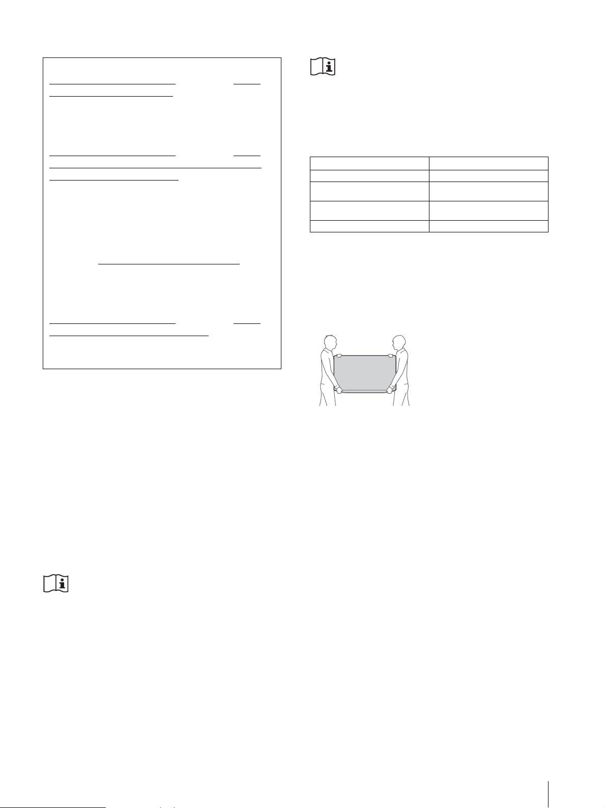
Caution
This unit is heavy. Make sure to unpack and move the
unit with two or more people.
Firmly grip the bottom of this unit as shown below.
LMD-X550MD only
Warning
This unit has no power switch.
To disconnect the main power, unplug the power plug.
When installing the unit, incorporate a readily accessible
disconnect device in the fixed wiring, or connect the
power plug to an easily accessible socket-outlet near the
unit.
Do not position the ME equipment where it is difficult
to unplug the power plug.
If a fault should occur during operation of the unit,
operate the disconnect device to switch the power supply
off, or unplug the power plug.
Warning on power connection
Use a proper power cord for your local power supply.
1. Use the approved Power Cord (3-core mains lead) /
Appliance Connector / Plug with earthing-contacts
that conforms to the safety regulations of each
country if applicable.
2. Use the Power Cord (3-core mains lead) / Appliance
Connector / Plug conforming to the proper ratings
(Voltage, Ampere).
If you have questions on the use of the above Power
Cord / Appliance Connector / Plug, please consult a
qualified service personnel.
7
Page 8

Table of Contents
Precaution ....................................................... 9
On Safety .................................................................. 9
On Installation ......................................................... 9
Precautions for using this unit safely .................... 9
Precautions for connecting this unit with other
medical devices ..................................................... 9
On simultaneous use with an electrosurgical
knife, etc. ................................................................ 9
Recommendation to Use more than One Unit ... 9
About the LCD Display Panel ............................... 9
About the Screen Protect Panel ........................... 10
On a Long Period of Use ...................................... 10
On Burn-in ............................................................ 10
On Fan Error .......................................................... 10
On Temperature Error .......................................... 10
On Moisture Condensation ................................. 10
On Cleaning ........................................................... 10
On Repacking ........................................................ 11
Disposal of the Unit .............................................. 11
Features ......................................................... 11
Location and Function of Parts and
Controls ........................................................ 13
Front Panel............................................................. 13
Input Signals and Adjustable/Setting Items....... 14
Rear/Bottom Panel................................................ 15
Connecting the AC Power Cord ................... 17
LMD-X310MD ...................................................... 17
LMD-X550MD ...................................................... 17
Removing the Connector Cover ................... 18
Configuration Example: 4K Surgical
Endoscope ..................................................... 19
Initial Setting ................................................20
Using the Menu .............................................22
Adjustment Using the Menus ....................... 23
Items ........................................................................ 23
Adjusting and changing the settings ................... 23
Color Tone Adjustment menu ...................... 23
Screen Control menu ...................................... 24
PIP / POP menu .............................................. 24
Input Configuration menu ............................ 25
System Configuration menu .......................... 25
Initial Setup menu ........................................... 26
Preset menu ...................................................... 27
Troubleshooting ...........................................27
Error Messages .............................................. 28
Specifications ................................................ 28
LMD-X310MD ...................................................... 28
LMD-X550MD ...................................................... 29
Dimensions ................................................... 35
LMD-X310MD ...................................................... 35
LMD-X550MD ......................................................35
LMD-X310MD/X550MD ....................................36
The terms HDMI and HDMI High-Definition
Multimedia Interface, and the HDMI Logo are
trademarks or registered trademarks of HDMI
Licensing LLC in the United States and other
countries.
8
Table of Contents
Page 9

Precaution
On Safety
LMD-X310MD is a DC powered device. Use with the
supplied AC adaptor (AC-300MD).
LMD-X550MD is an AC powered device.
Operate the unit on 100-240 V AC only.
The nameplate indicating operating voltage, etc. is
located on the AC adaptor.
Should any solid object or liquid fall into the cabinet,
unplug the unit and have it checked by qualified
personnel before operating it any further.
Unplug the unit from the wall outlet if it is not to be
used for several days or more.
To disconnect the AC power cord, pull it out by
grasping the plug. Never pull the cord itself.
The socket-outlet shall be installed near the
equipment and shall be easily accessible.
On Installation
Precautions for connecting this unit with other medical devices
Before you utilize this device and/or connect this
device to any other medical device, please be aware of
and abide by the following precautions:
(a) Before actually using this device for medical
practice, please check and confirm that you do not
experience any discomfort in your use that could be
disruptive or impeditive in conducting your intended
activity or medical practice.
(b) If you experience or are likely to experience such
discomfort, please refrain from using this device.
(c) Generally, discomfort (such as eye strain, fatigue,
nausea, or motion sickness) can be provoked by such
factors as quick movements or shakiness of video
picture, focal position of video pictures, distance
between objects and image capturing modules, user’s
point of gaze in video pictures, other varying
conditions of video pictures to be input to this device,
and individual user’s health conditions.
Before you utilize this unit, check if the image of the
connected medical device is displayed properly on the
screen of this unit.
Prevent internal heat build-up allowing adequate air
circulation.
Do not place the unit on surfaces (rugs, blankets, etc.)
or near materials (curtains, draperies) that may block
the ventilation holes.
Do not install the unit near heat sources such as
radiators or air ducts, or in a place subject to direct
sunlight, excessive dust, mechanical vibration or
shock.
Do not place the monitor near equipment which
generates magnetism, such as a transformer or high
voltage power lines.
Precautions for using this unit safely
Some people may experience discomfort (such as eye
strain, fatigue, or nausea) while watching video
images. Sony recommends that all viewers take regular
breaks while watching video images. The length and
frequency of necessary breaks will vary from person to
person. You must decide what works best.
Avoid watching the display in environments where
your head may shake, or while you are walking or
performing exercise, because there is a higher
possibility that you experience discomfort.
On simultaneous use with an electrosurgical knife, etc.
If this unit is used together with an electrosurgical knife,
etc., the picture may be disturbed, warped or otherwise
abnormal as a result of strong radio waves or voltages
from the device. This is not a malfunction.
When you use this unit simultaneously with a device
from which strong radio waves or voltages are emitted,
confirm the effect of this before using such devices, and
install this unit in a way that minimizes the effect of
radio wave interference.
Recommendation to Use more than One Unit
As problems can occasionally occur for the monitor,
when the monitor is used for safety control of personnel,
assets or stable picture, or for emergencies, we strongly
recommend you use more than one unit or prepare a
spare unit.
About the LCD Display Panel
The LCD panel fitted to this unit is manufactured with
high precision technology, giving a functioning pixel
ratio of at least 99.99%. Thus a very small proportion
Precaution
9
Page 10

of pixels may be “stuck”, either always off (black),
always on (red, green, or blue), or flash ing . In additio n,
over a long period of use, because of the physical
characteristics of the liquid crystal display, such
“stuck” pixels may appear spontaneously. These
problems are not a malfunction.
Do not leave the LCD screen facing the sun as it can
damage the LCD screen. Take care when you place the
unit by a window.
Do not push or scratch the LCD screen. Do not place
a heavy object on the LCD screen. This may cause the
screen to lose uniformity.
If the unit is used in a cold place, a residual image may
appear on the screen. This is not a malfunction. When
the monitor becomes warm, the screen returns to
normal.
The screen and the cabinet become warm during
operation. This is not a malfunction.
About the Screen Protect Panel
The screen protect panel is made of toughened glass, but
there is a possibility that it may crack. Handle with care.
Avoid strong impact, such as dropping from a high
place.
Do not damage the panel with a sharp object. The glass
may crack due to the damage.
On a Long Period of Use
Due to the characteristics of LCD panel, displaying static
images for extended periods, or using the unit repeatedly
in a high temperature/high humidity environments may
cause image smearing, burn-in, areas of which
brightness is permanently changed, lines, or a decrease
in overall brightness.
In particular, continued display of an image smaller than
the monitor screen, such as in a different aspect ratio,
may shorten the life of the unit.
Avoid displaying a still image for an extended period, or
using the unit repeatedly in a high temperature/high
humidity environment such an airtight room, or around
the outlet of an air conditioner.
To prevent any of the above issues, we recommend
reducing brightness slightly, and to turn off the power
whenever the unit is not in use.
Images that may cause burn-in
Masked images with aspect ratios other than 17:9 for
the LMD-X310MD and 16:9 for the LMD-X550MD
Color bars or images that remain static for a long time
Character or message displays that indicate settings or
the operating state
To reduce the risk of burn-in
Tu r n off th e c h aracte r d i splays
Press the MENU button to turn off the character
displays. To turn off the character displays of the
connected equipment, operate the connected
equipment accordingly. For details, refer to the
operation manual of the connected equipment.
Turn off the power when not in use
Turn off the power if the monitor is not to be used for
a prolonged period of time.
On Fan Error
The fan for cooling the unit is built in. When the fan
error indication appears on the screen, turn off the
power and contact an authorized Sony dealer.
On Temperature Error
When this unit is used in a high temperature
environment and the internal temperature rises, an error
is displayed on the screen. When the error is displayed,
contact an authorized Sony dealer.
On Moisture Condensation
If the unit is suddenly taken from a cold to a warm
location, or if ambient temperature suddenly rises,
moisture may form on the outer surface of the unit and/
or inside of the unit. This is known as condensation. If
condensation occurs, turn off the unit and wait until the
condensation clears before operating the unit. Operating
the unit while condensation is present may damage the
unit.
On Cleaning
Before cleaning
Be sure to disconnect the AC power cord from the AC
outlet.
On Burn-in
For LCD panel, permanent burn-in may occur if still
images are displayed in the same position on the screen
continuously, or repeatedly over extended periods.
10
Precaution
On cleaning the monitor
A material that withstands disinfection is used for the
front protection plate of the medical use LCD monitor.
The protection plate surface is specially treated to reduce
reflection of light. When solvents such as benzene or
Page 11

thinner, or acid, alkaline or abrasive detergent, or
chemical cleaning cloth are used for the protection plate
surface/monitor surface, the performance of the
monitor may be impaired or the finish of the surface may
be damaged. Take care with respect to the following:
Clean the protection plate surface/monitor surface
with a 50 to 70 v/v% concentration of isopropyl
alcohol or a 76.9 to 81.4 v/v% concentration of ethanol
using a swab method. Wipe the protection plate
surface gently (wipe using less than 1 N force).
Stubborn stains may be removed with a soft cloth such
as a cleaning cloth lightly dampened with mild
detergent solution using a swab method and then
clean using the above chemical solution.
Never use solvents such as benzene or thinner, or acid,
alkaline or abrasive detergent, or chemical cleaning
cloth for cleaning or disinfection, as they will damage
the protection plate surface/monitor surface.
Do not use unnecessary force to rub the protection
plate surface/monitor surface with a stained cloth. The
protection plate surface/monitor surface may be
scratched.
Do not keep the protection plate surface/monitor
surface in contact with a rubber or vinyl resin product
for a long period of time. The finish of the surface may
deteriorate.
On Repacking
Do not throw away the carton and packing materials.
They make an ideal container which to transport the
unit.
If you have any questions about this unit, contact your
authorized Sony dealer.
Disposal of the Unit
Features
Compliance with medical safety standards
in U.S.A., Canada and Europe
IEC 60601-1 and product safety standards in the U.S.A.,
Canada and Europe have been obtained for this monitor.
The monitor is designed for use in the medical treatment
field, with the sheet switch, screen protect panel, etc.
High brightness/high-resolution 4K panel
A 4K high-resolution panel and high brightness/ultrawide field of view technology enables you to use the
monitor under various lighting conditions and in
numerous ways (installing on the wall, using several
monitors to view an image, etc.). Because a color filter
with wide-color reproduction and LCD materials with
high response speed are used, the motion picture of the
video signal is displayed more clearly.
A.I.M.E. (Advanced Image Multiple
Enhancer) function
There are two modes in the A.I.M.E. function – the
“Structure Enhancement mode” and “Color
Enhancement mode.”
Users can select four levels for the Structure
Enhancement mode and eight levels for the Color
Enhancement mode, depending on their preference.
By utilizing the A.I.M.E. function, users can expect the
following effects on displayed images.
Color Enhancement Function
This function clarifies color tone differences between
objects.
Do not dispose of the unit with general waste.
Do not include the monitor with household waste.
About this manual
The instructions in this manual are for the following
models:
LMD-X310MD
LMD-X550MD
The illustration of LMD-X310MD is used for the
explanations. Any differences in specifications are
clearly indicated in the text.
Structure Enhancement Function
This function improves recognition of the outline of
objects. Visibility becomes clear making it easy to see
objects.
The A.I.M.E. Color Enhancement Function emphasizes
the contrast of R, G, B signals automatically but does not
allow users to select a specific color.
Users can only select the degree of contrast, which
increases from levels C1 (minimum) to C8 (maximum).
The A.I.M.E. Structure Enhancement Function
emphasizes the outline and edges of objects.
Users can select the degree of the structure enhancement
level, which increases from levels S1 (minimum) to S4
(maximum).
The image may seem blurred by applying the A.I.M.E.
Color Enhancement Function.
Feat ures
11
Page 12
The blur can be compensated for by using the A.I.M.E.
Structure Function at the same time.
Users can select the degree of the structure enhancement
from levels S1 (minimum) to S4 (maximum) for this
purpose according to their preference.
A.I.M.E. is a registered trademark of Sony Corporation.
A.I.M.E. is an optional function for enhancing the color
or structure of the displayed image.
Like the other settings of the monitor, users must adjust
or deactivate A.I.M.E. when appropriate.
Screen protect panel
OptiContrast panel
The “OptiContrast” design that fills up the air layer
between the LCD panel and screen protect panel with
bonding resin is employed. By eliminating the air layer,
this panel prevents diffused reflection and decrease in
contrast. It also prevents condensation due to rapid
temperature change.
Control panel
Assigns functions frequently used during an operation
to buttons on the front surface of the monitor. The panel
provides an user interface superior in operability
through navigation by luminescent colors and status of
the buttons.
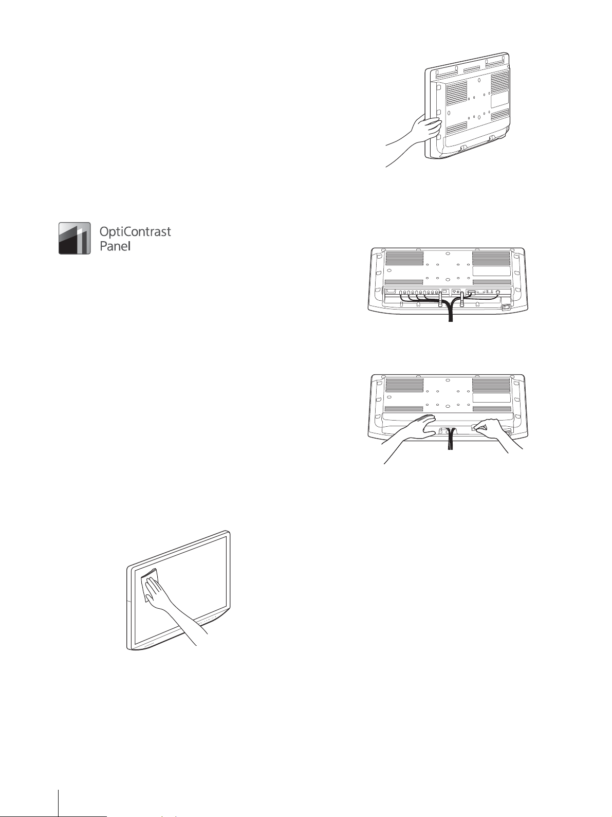
Flat surface for better maintenance
The design allows the user to easily wipe liquids and gel
off the LCD panel and control buttons – ensuring a high
standard of disinfection and cleanliness.
Simple connector notation
All the connectors face downwards, allowing for easy
and organized cable connection.
Cover designed for attachment
Grip that is easy to hold
The easy-to-grip ergonomic design enables the user to
make tiny adjustments simply and quickly.
12
Features
Page 13

Location and Function of Parts and Controls
Front Panel
Power indicator
When the power is turned on, the power indicator lights
in green.
When the protection function is activated and the
display brightness is reduced due to the rise in
temperature, it flashes in amber.
CONTROL button
Displays or clears the operating buttons on the front
panel.
Selects the items depending on the menu types.
OSD menu operation buttons
MENU button
Press to display the on-screen menu.
Press again to clear the menu.
/// buttons
Press to select the items and setting values.
CUSTOM button
Turns on or off the assigned function. You can adjust the
assigned function by pressing the / buttons. (Refer to
the custom buttons of the system configuration menu on
page 26 and of the default setting on page 27.)
The following functions are assigned in the default
setting.
CUSTOM 1: Brightness
CUSTOM 2: Contrast
CUSTOM 3: Flip
A.I.M.E. button
Sets the A.I.M.E.
A.I.M.E. function is set to On, A.I.M.E. Structure and
A.I.M.E. Color can be adjusted.
1) A.I.M.E.: Enables better image reproduction and display.
2 or 3 screen display setting buttons
PIP/POP: For displaying the 2 or 3 screen display
or switching the 2 or 3 screen display mode.
SWAP: For swapping between the main display
and the sub display.
Input select buttons
PORT A: Displays the input signal assigned to
PORT A. When the input signal of PORT A is
displayed, a menu which allows you to select the input
signal to be assigned to PORT A is displayed.
1)
function to Off and On. When the
Location and Function of Parts and Controls
13
Page 14

PORT B: Displays the input signal assigned to
PORT B. When the input signal of PORT B is
displayed, a menu which allows you to select the input
signal to be assigned to PORT B is displayed.
Input Signals and Adjustable/Setting Items
Item
Gamma
Phase
Chroma
Brightness
Contrast
A.I.M.E.
Gradation Extension
Color Temperature
Mono
Sharpness H
Sharpness V
RGB Range
Color Space
4K Scan Size
HD Scan Size
SD Scan Size
Zoom
Flip Pattern
SD Aspect
Interface Mode
: Can be adjusted/set
× : Cannot be adjusted/set
SDI 1 SDI 2
××
1)
2)
3)
3)
ЧЧЧЧЧ
×××
2)
3)
3)
(ON/STANDBY) switch
Press the side to turn the monitor on. Press the side
to switch the unit to the standby state, and the indicator
light turns off.
Input signal
DVI-D HDMI
Video PC Video PC
1)
2)
3)
3)
4)
×
4)
×
4)
×
2)
3)
3)
4)
×
4)
×
4)
×
4)
×
1) Reflected on the screen only when the 4K signal is input.
2) Reflected on the screen only when the HD signal is input.
3) Reflected on the screen only when the SD signal is input.
4) The setting value can be changed but is not applied to the screen when
the PC signal is input.
14
Location and Function of Parts and Controls
Page 15

Rear/Bottom Panel
LMD-X310MD
LMD-X550MD
Close
Cable
HDMI cable holder
Secures the HDMI cable (Ø7 mm or less).
HDMI input connector
Input connector for HDMI signals.
Use HighSpeed HDMI Cable with Cable Type Logo.
(Recommend Sony Cable.)
3G/HD/SD-SDI input/output connector (BNC
type)
SDI 1 (4K/HD)
connector (input)
Input connector for serial digital component signals
connector (output)
Signals input to the input connector are output to the
output connector.
1) Serial digital component signals are SMPTE 259M
compliant (SD)/SMPTE 292M compliant (HD)/ SMPTE
424M compliant (3G).
For the HD/SD quad view setting, each connector is
compatible with the four division-images shown below.
1)
.
3G/HD/SD-SDI input/output connector (BNC
type)
Location and Function of Parts and Controls
15
Page 16

SDI 2 (HD)
Note
connector (input)
Input connector for serial digital component signals
1)
connector (output)
Signals input to the input connector are output to the
output connector.
1) Serial digital component signals are SMPTE 259M
compliant (SD)/SMPTE 292M compliant (HD)/ SMPTE
424M compliant (3G).
SERIAL REMOTE connector (RJ-45)
Connect to the network by using a 10BASE-T/100BASETX LAN cable (non-shielded type of 5 or more category,
optional).
The monitor can be operated according to control
commands sent from connected external equipment.
Consult your dealer in order to utilize the function.
For safety, do not connect the connector for peripheral
device wiring that might have excessive voltage to this
port. Follow the instructions for this port.
The connection speed may be affected by the network
system. This unit does not guarantee the
communication speed or quality of 10BASE-T/
100BASE-TX.
1) HDCP (High-bandwidth Digital Content Protection) is a
copyright protection technology using encryption
.
technology of digital video signals.
SERIAL REMOTE RS-232C connector (D-sub
9-pin, female)
The monitor can be operated according to control
commands sent from connected external equipment.
(DC 26 V input) connector (LMD-X310MD
only)
Connects the DC connector of the supplied AC adaptor.
Connect the DC connector to the unit, then connect the
power cord of the AC adaptor.
To remove the DC connector, remove the power cord of
the AC adaptor, then remove the DC connector.
For the DC power supply, make sure to use the supplied
AC adaptor, AC-300MD. If another power supply is
used, there is a risk of fire or electric shock.
(equipotential) terminal
Connects the equipotential plug.
Do not come into contact with the terminals of the rear
panel connectors and patients at the same time.
Doing so may result in a generation of voltage that can be
harmful to patients if the unit is malfunctioning.
Always disconnect the power cord before connecting
and disconnecting connectors.
12V 1.7A output connector
Outputs 12 volts. (A connector for an option for future
use)
5V 1.6A output connector
Outputs 5 volts. (A connector for an option for future
use)
DVI-D input/output connector
connector (input)
Input DVI Rev.1.0 applicable digital signal.
connector (output)
Active through output connector of the DVI digital
signal.
(AC input) connector (LMD-X550MD only)
Connects the supplied AC power cord.
Using this unit for medical purposes
This equipment’s connectors are not isolated.
Do not connect any device other than one which
conforms to IEC60601-1.
When an information technology device or AV device
that uses an alternating current is connected, current
leakage may result in an electric shock to the patient or
operator.
If use of such a device is unavoidable, isolate its power
supply by connecting an isolation transformer, or by
connecting an isolator between the connecting cables.
After implementing these measures, confirm that the
reduced risk now conforms to IEC60601-1.
Signals are output when the power is on. No signal is
output when the power is off. Signals protected with
HDCP
16
Location and Function of Parts and Controls
1)
cannot be output.
Page 17

Connecting the AC Power
AC IN connector
AC power cord
AC power plug holder
AC input
connector
AC power cord
AC power plug
holder
Cord
LMD-X310MD
1
Make sure that the switch is set to (in a
standby state).
2
Insert the DC connector to the DC 26 V input
connector of the rear panel until it locks.
5
Connect the plug of the AC power cord to an AC
outlet.
To remove the AC power cord
Press the switch to the side and switch the unit to
the standby state, then remove the AC power cord from
the AC power plug holder by holding the fixing levers of
the holder from both sides to release the lock. Then,
remove the DC connector from the unit.
LMD-X550MD
1
Make sure that the switch is set to (in a
standby state).
3
Plug the AC power cord into the AC IN connector
of the AC adaptor and attach the AC power plug
holder to the AC power cord.
4
Insert the AC power plug holder until the fixing
lever locks.
2
Insert the AC power cord to the AC input connector
of the rear panel and attach the AC power plug
holder to the AC power cord.
3
Insert the AC power plug holder until the fixing
lever locks.
Connecting the AC Power Cord
17
Page 18

4
LMD-X310MD
Clamp
Connect the plug of the AC power cord to an AC
outlet.
To remove the AC power cord
Press the switch to the side and switch the unit to
the standby state, then remove the AC power cord from
the AC power plug holder by holding the fixing levers of
the holder from both sides to release the lock.
Removing the Connector Cover
To use the connector, remove the connector cover as
follows.
Before removing the connector cover, disconnect the
power cord.
1
Loosen the two screws.
2
Slide the connector cover in the direction of the
arrow and remove it.
3
Remove the two screws and cable clamp.
Do not remove screws other than the two screws
fixing the clamp. Doing so may cause electric shock.
18
Removing the Connector Cover
Page 19

4
LMD-X550MD
Clamp
4K Monitor (Main)
4K Monitor (Sub)
(1) 3G-SDI × 4
(2) 3G-SDI × 4
RS-232C
3G-SDI × 4
HDMI
RS-232C
4K Endoscope or
4K Imaging System
4K Recorder
Position the connecting cable under the attaching
cable clamp.
5
Attach the connector cover.
When using a thick connecting cable that cannot be
positioned under the attaching cable clamp or connector
cover, do not forcefully fix the cable. Use the unit with
the connector cover removed.
Configuration Example: 4K Surgical Endoscope
The 4K monitors can be configured with a 4K endoscope
and 4K recorder as below.
The monitor parameter can be controlled from an
external device via RS-232C interface.
This unit with the connector cover attached conforms to
the waterproofed standard. (LMD-X310MD: See page
29, LMD-X550MD: See page 30)
Note that if the unit is used with the connector cover
removed, its waterproof performance is not guaranteed.
Configuration Example: 4K Surgical Endoscope
19
Page 20

Initial Setting
Note
When you turn on the unit for the first time after
purchasing it, select the area and language where you
intend to use this unit from among the options.
To set the using area
Color Temperature
North America
Latin America - Argentina
Latin America - Paraguay
Latin America - Uruguay
Latin America - Other
Africa, Australasia
Europe, Middle-East
Asia Except Japan - NTSC
Asia Except Japan - PAL
Japan
1
Tur n on t h e u n i t.
D65
D65
D65
D65
D65
D65
D65
D65
D65
D93
3
Press the or button to select the area where you
intend to use the unit and press the button.
When the confirmation screen is displayed, press
the or button to select Yes and press the
CONTROL button.
If you select Asia Except Japan
Customers who will use this unit in the shaded
areas shown in the map below except for Japan
should select NTSC AREA.
Other customers should select PAL AREA.
4
The Area Selection screen disappears and the menu
item settings suitable for the selected area are
applied.
When you have selected the wrong area, set the
following items using the menu.
Color Temperature (on page 24)
See “To set the using area” (page 20) on the setting value.
20
The Area Selection screen appears.
2
Press the CONTROL button.
Initial Setting
To set the using language
You can select one of seven languages (English, Chinese,
Japanese, Italian, Spanish, German, French) for display
on the menu and other on-screen displays. The default
menu language is set to “English.”
1
Tur n on t h e u n it.
Select the area where you intend to use this unit on
the Area Selection screen. (See page 20.)
2
The Language Setting screen is displayed.
Page 21

3
Press the or button to select the language and
press the button.
When the confirmation screen is displayed, press
or button to select Yes and press the CONTROL
button.
4
Press the / button to select “Language.”
The selected item is displayed in blue.
5
Press the / button to select a language.
The menu changes to the selected language.
To change the menu language
Select the area and language which you use. See this
section when you change the using language.
1
Press the MENU button.
The menu-selecting screen appears.
The menu presently selected is shown in blue.
2
Press the / button to select “System
Configuration.”
When you press the or CONTROL button, the
“System Configuration” menu is displayed and the
selected tab is shown in blue.
To clear the menu
Press the MENU button.
The menu disappears automatically if a button is not
pressed for one minute.
3
Press the / button to select the “OSD Setting”
tab.
The “OSD Setting” menu appears.
Initial Setting
21
Page 22

Using the Menu
The selected tab is shown in blue, and setting items
of the selected tab appear.
5
Select an item.
The unit is equipped with an on-screen menu for
making various adjustments and settings such as picture
control, input setting, setting change, etc.
To change the menu language, refer to “To change the
menu language” on page 21.
1
Press the CONTROL button.
The operation buttons are displayed.
2
Press the MENU button.
The menu-selecting screen appears.
The menu presently selected is shown in blue.
Press the / button to select the item.
The item to be changed is displayed in blue.
6
Make the setting or adjustment on an item.
When changing the adjustment level:
To increase the number, press the button.
To decrease the number, press the button.
When selecting the setting:
Press the / button to select the setting.
If the Control Lock is set to “On,” the setting cannot
be changed.
For details about Control Lock, see page 25.
About the memory of the settings
The settings are automatically stored in the monitor
memory.
When the power is turned off, the setting value of
A.I.M.E. is set to “Off.”
About the control navigation
Depending on the state, the operating buttons of the unit
light as shown below:
White light: Operable state.
Green light: Operating state.
Off: Unable to operate.
3
Press the / button to select a menu.
When you press the or CONTROL button, the
selected menu appears and setting items of the
selected tab are displayed.
4
Press the / button to select the tab.
22
Using the Menu
Page 23

Adjustment Using the Menus
Items
The screen menu of this monitor consists of the
following items.
System Configuration
Control Lock
OSD Setting
Power On Setting
Power Save
Serial Remote
Ethernet Setting
Custom Button
Panel Display
Monitor Information
Color Tone Adjustment
Gamma
Phase
Chroma
Brightness
Contrast
A.I.M.E.
A.I.M.E. Structure
A.I.M.E. Color
Gradation Extension
Color Temperature
Gain R Offset
Gain G Offset
Gain B Offset
Bias R Offset
Bias G Offset
Bias B Offset
Mono
Sharpness H
Sharpness V
RGB Range
Color Space
Screen Control
4K Scan Size
HD Scan Size
SD Scan Size
Zoom
Flip Pattern
SD Aspect
Interface Mode
PIP / POP
3 Screen Display
Clipping Size
Sub Screen Position
Pattern Skip
Initial Setup
Language
Pattern Skip
PIP / POP
Custom Button
Preset
Load User Setting
Save User Setting
User Name
Load Default
Adjusting and changing the settings
Color Tone Adjustment menu
The Color Tone Adjustment menu is used to adjust
picture quality for each input.
You need to use the measurement instrument to adjust
the color temperature.
Recommended: Konica Minolta color analyzer CA-310
Submenu Setting
Gamma Select the appropriate gamma mode
from among “1.8,” “2.0,” “2.2,” “2.4,”
“2.6,” “DICOM,” “Highlight.”
“DICOM” is for reference, not
diagnostic, purposes only.
Phase Adjusts color tones. The higher the
setting, the more greenish the picture.
The lower the setting, the more purplish
the picture.
Chroma Adjusts color intensity. The higher the
setting, the greater the intensity. The
lower the setting, the lower the
intensity.
Brightness Adjusts brightness.
Contrast Adjusts contrast.
Input Configuration
Input Name
HDCP Setting
Adjustment Using the Menus
23
Page 24

Notes
Note
Submenu Setting
Note
Note
A.I.M.E. Select from among “Off,” “On” and
“Check Mode.”
When you select “Check Mode,” two
images of A.I.M.E.
1)
being “Off” / “On”
are displayed.
1) A.I.M.E.: Enables better image
reproduction and display.
A.I.M.E. Logo is displayed on the
display area where the A.I.M.E.
function is activated.
When the HD/SD quad view is set,
A.I.M.E. functions for only the SDI
1-A input.
When the PIP/POP view is set,
A.I.M.E. functions for only the main
display.
A.I.M.E. Structure Adjusts the contrast enhancement.
A.I.M.E. Color Adjusts the color enhancement.
Gradation Extension Displays the expanded gradation of a
specific color.
Select “On” or “Off.”
Color Temperature Select the color temperature from
among “D65,” “D93.”
Screen Control menu
The Screen Control menu is used to set the image display
setting for each input.
Submenu Setting
4K Scan Size Select the scan size for the 4K signal
display.
Select “Off” or “Mode7.”
HD Scan Size Sets the scan size for the HD signal
display of 1920 × 1080.
Select from among “Off,” “Mode2,”
“Mode3,” “Mode4,” “Mode5,” “Mode6.”
SD Scan Size Sets the scan size for the SD signal
display.
Select from among “Off,” “Mode1.”
Zoom Video signals can be enlarged in the
specified ratio.
Select from among “Off,” “x1.2,” “x1.5,”
“x2.0.”
Zoom is available only when the
horizontal resolution is 1280 dots or
more.
Flip Pattern Sets the flip pattern of the display.
Select from among “Off,” “Rotation.”
If the setting is changed, Gain R/G/B
Offset and Bias R/G/B Offset are
restored to 0 respectively.
Gain R Offset
Gain G Offset
Adjust color temperature in detail, and
color balance (Gain).
Gain B Offset
Bias R Offset
Bias G Offset
Adjust color temperature in detail, and
color balance (Bias).
Bias B Offset
Mono Sets the display to a monochrome
picture. Set to “On” for a monochrome
picture, set to “Off” for a normal
(chromatic) picture.
Sharpness H Adjusts the horizontal sharpness. The
higher the setting, the sharper the
picture. The lower the setting, the softer
the picture.
Sharpness V Adjusts the vertical sharpness. The
higher the setting, the sharper the
picture. The lower the setting, the softer
the picture.
RGB Range Sets the RGB signal range. Select from
among “Auto,” “Limited,” “Full.” If you
set to “Auto,” this item is set to
“Limited” when inputting video signal,
and “Full” when inputting PC signals.
Color Space Select the color gamut from among
“BT.709,” “Native,” “BT.2020,” “Auto.”
When images are rotated, the delay
amount will be one frame longer than
the normal time. Use the unit
considering the delay amount of the
entire system.
SD Aspect Sets the aspect ratio of the SD signal
display.
Select from among “4:3,” “16:9.”
Interface Mode Select the interface mode.
4K Quad: Select to display the 4K
signal input to the A to D
connector of SDI 1.
4K Dual: Select to display the 4K
signal input to the A or B
connector of SDI 1.
HD Dual: Select to display the HD
signal input to the A or B
connector of SDI 1.
HD/SD Single: Select to display the
HD or SD signal input to the A
connector of SDI 1.
HD/SD Quad View: Select to display
the HD or SD signal input to the
A to D connector of SDI 1 in
images divided in four.
PIP / POP menu
The PIP / POP menu is used to set the display mode for
the 2 or 3 screens display and for each input.
24
Adjustment Using the Menus
Page 25

Note
Note
Select Port
Input connector
Control lock display
Signal Format
display
Flip
Pattern
PIP/POP mode
display
A.I.M.E. display
Scan/Zoom mode
Submenu Setting
3 Screen Display
Port C Display Sets the display of the sub screen for the
third screen.
Select “On” or “Off.”
Port C Input Sets the input connector for the third
screen.
Select from among “SDI 1,” “SDI 2,”
“DVI-D,” “HDMI.”
Clipping Size Sets the HD of 1920 × 1080 clipping size
for each port when using 2 or 3 screens
display.
Select from among “Normal,” “4:3,”
“5:4,” “Overscan.”
Sub Screen Position
PIP Sets the sub screen position for the 2 or
3 screens display (PIP).
Select from among “Lower Left,”
“Upper Left,” “Upper Right,” “Lower
Right.”
POP Sets the sub screen position for the 2 or
3 screens display (POP).
Select from among “Right,” “Left.”
Signals equivalent to 4K can display
only 1 screen for multiple displays.
For the signal type for using signals
equivalent to 4K, refer to “Available
signal formats” (page 31).
Pattern Skip Sets the pattern that is skipped when
changing the displaying pattern by
pressing the PIP/POP button on the
front panel while displaying 2 or 3
screen displays.
Set to “Not Skip” or “Skip” for the PIP1,
PIP2, POP1, or POP2 pattern.
Input Configuration menu
Submenu Setting
Input Name Sets the name for each input connector.
Set the name of the SDI 1, SDI 2, DVID, HDMI connector.
Endoscope
Laparoscope
Ultrasound
Recorder
Printer
PA CS
C-arm
Room Camera
Surgical Camera
Microscope
Vital Device
Submenu Setting
HDCP Setting Sets the HDCP setting for signals input
in the DVI-D connector.
Enable: Sets to use the signals
protected with HDCP.
Disable: Sets to use the signals not
protected with HDCP. When
“Disable” is set for the signals
not protected with HDCP,
signals are output from the DVID connector.
When “Disable” is set for the signals
protected with HDCP, images are not
displayed.
System Configuration menu
Submenu Setting
Control Lock
Control Lock Set when you want to limit the
operation of the control panel. Set to
“Off” for no limit, “On” to limit.
Lock Mode Sets the range to limit the operation of
the control panel. This setting is
available when “Control Lock” is set to
“On.”
Menu: Limits the menu operations
other than the control lock
setting.
Menu&Button: Limits all operations
other than the control lock
setting.
OSD Setting
Menu Position Sets the menu position.
Select from among “Upper Left,”
“Upper Right,” “Lower Right,” and
“Lower Left.”
Status Display Port, input connector name, control
lock, signal format, Scan/Zoom mode,
Flip Pattern, PIP/POP mode, and
A.I.M.E. are displayed.
Adjustment Using the Menus
25
Page 26

Notes
Submenu Setting
Input Signal format
display
No signal No Sync
Non compatible
signal (except for
DVI-D, HDMI)
Unknown
Non compatible
signal (DVI-D,
HDMI)
Out Of Range
Language You can select the menu or message
Power On Setting
Power On Mode Selects the setting when the monitor is
Logo Select the logo when the power turns on
Power Save
Energy Saving
Mode
Sleep Mode Sets the sleep mode to on or off. When
26
Adjustment Using the Menus
Auto: The format and scan mode are
displayed for about 3 seconds
when the content of Status
Display is changed.
On: The format and scan mode are
always displayed.
Off: The format and scan mode are
not displayed.
Even if the setting is set to “Auto” or
“Off,” the flip pattern is available.
For details about the signal format,
refer to no signal and incompatible
signal displays.
language from the following languages.
English: English
: Chinese
: Japanese
Ital iano : Ita lian
Español: Spanish
Deutsch: German
Français: French
turned on from the following settings.
Last: The setting when the monitor
was last turned off.
Default Setting: The setting that is
set in the default setting.
User1 to 20: The selected user setting.
from among “On - 5sec,” “On - 10sec,”
“Off.”
Selects the energy saving mode.
Off: Turns the energy saving mode
off.
On: Dims the backlight.
you set to “On,” the monitor enters into
power saving mode by turning off the
backlight if there is no input signal from
the selected connector for more than 1
minute.
Submenu Setting
Serial Remote
Serial Remote Selects the using mode.
Off: Disables the serial remote
function.
RS-232C: Controls this unit via RS-
232C command.
Ethernet: Controls this unit via
Ethernet command.
Ethernet Setting Sets the Ethernet.
IP Address: Sets the IP Address.
Subnet Mask: Sets the Subnet Mask.
Default Gateway: Sets “On” or “Off”
of the Default Gateway.
Address: Sets the Default Gateway.
Custom Button Assigns the function to the CUSTOM 1,
CUSTOM 2 or CUSTOM 3 button on
the front panel, and can set the
following functions to on or off.
No Setting
Scan Size
Zoom
Flip
POP Sub Screen Position
Gamma
Mono
Phase
Chroma
Brightness
Contrast
Port C Display
Panel Display
Backlight Adjusts the brightness of the display. A
higher setting increases the brightness
of the display, and a lower setting
darkens the display.
Monitor Information
Software Version Displays the software version.
Initial Setup menu
The Initial Setup menu is used to make the basic settings
to use the unit.
Submenu Setting
Language You can select the menu or message
language from the following languages.
English: English
: Chinese
: Japanese
Ital iano : Italian
Español: Spanish
Deutsch: German
Français: French
Pattern Skip Sets the pattern that is skipped when
changing the displaying pattern by
pressing the PIP/POP button on the
front panel while using 2 or 3 screens
display.
Set to “Not Skip” or “Skip” for the PIP1,
PIP2, POP1, or POP2 pattern.
Page 27

Submenu Setting
PIP / POP
PIP Sub Screen
Position
POP Sub Screen
Position
PORT A/PORT B
HD Clipping Size
Custom Button Assigns the function to the CUSTOM 1,
Sets the sub screen position for the 2 or
3 screen displays (PIP).
Select from among “Lower Left,”
“Upper Left,” “Upper Right,” “Lower
Right.”
Sets the sub screen position for the 2 or
3 screen displays (POP).
Select from among “Left,” “Right.”
Sets the HD of 1920 × 1080 clipping size
for each port when displaying 2 or 3
screen displays.
CUSTOM 2 or CUSTOM 3 button on
the front panel, and can set the
following functions to on or off.
No Setting
Scan Size
Zoom
Flip
POP Sub Screen Position
Gamma
Mono
Phase
Chroma
Brightness
Contrast
Port C Display
Troubleshooting
This section may help you isolate the cause of a problem
and as a result, eliminate the need to contact technical
support.
The unit cannot be operated The key protection
function is enabled. Set the Control Lock setting to Off
in the Control Lock menu.
The black bars appear at the upper and lower
positions of the display When the signal aspect
ratio is different from that of the panel, the black bars
appear. This is not a failure of the unit.
Fan noise occurs. When the unit is used in a high
temperature environment, the fan operates to lower
the temperature. Noise will occur, but this is not due to
failure.
The DVI-D signal image is not displayed. When
inputting the signal protected with HDCP in the DVID connector and the HDCP setting is set to
“Disable,” the image is not displayed on the screen.
Set the HDCP setting to “Enable.”
The display is dark. When the unit is used in a
high temperature environment, the brightness of the
display backlight is reduced to lower the temperature
inside the unit. When this function is activated, the
power indicator flashes in amber.
Preset menu
The Preset menu is used to set the A to T and user 1 to
20 preset settings.
Submenu Setting
Load User Setting Loads the settings that are stored User1
Save User Setting Stores the current settings to User1 to
User Name Registers the user names to User1 to 20.
Load Default Loads the default settings.
to 20.
20.
Troubleshooting
27
Page 28

Error Messages
Specifications
When the following messages appear on the screen, turn
off the power and contact an authorized Sony dealer.
Messages Description
Fan Error A malfunction occurs in the fan.
Temperature Error The temperature of this unit has
increased to an abnormal level.
LMD-X310MD
Picture performance
LCD panel a-Si TFT Active Matrix
Pixel efficiency 99.99%
Viewing angle (Panel specification)
89°/89°/89°/89° (typical) (up/down/
left/right, contrast > 10:1)
Efficient picture size
697.958 × 368.064, 789.06 mm (w/h,
dia) (27
Resolution H 4,096 dots, V 2,160 lines
Aspect ratio 17:9
Input
HDMI input connector
HDMI connector (1), HDCP 1.4
correspondence
DVI-D input connector
DVI-D connector (1)
TMDS single link, HDCP 1.4
correspondence
3G/HD/SD-SDI input connector
BNC type (5), 75Ω
SD: SMPTE 259M compliant
HD: SMPTE 292M compliant
3G: SMPTE 424M compliant
Remote input connector
Serial remote
D-sub 9-pin (RS-232C) (1)
RJ-45 modular connector
(ETHERNET) (1)
DC IN connector
DC 26 V
1
/2 × 14 1/2, 31 1/8 inches)
28
Error Messages / Specifications
Output
DVI-D output connector
DVI-D connector (1)
3G/HD/SD-SDI output connector
BNC type (5)
DC 12V OUT Round type pin (female) (1)
DC 5V OUT Round type pin (female) (1)
General
Power DC IN: 26 V 6.9 A (Supplied from AC
adaptor)
Page 29

Operating conditions
Te mp e r a tu r e
0 °C to 40 °C (32 °F to 104 °F)
Recommended temperature
20 °C to 30 °C (68 °F to 86 °F)
Humidity 30% to 85% (no condensation)
Pressure 700 hPa to 1060 hPa
Storage and transport conditions
Te mp e r a tu r e
–20 °C to +60 °C (–4 °F to +140 °F)
Humidity 0% to 90%
Pressure 700 hPa to 1060 hPa
Accessories supplied
AC adaptor (AC-300MD) (1)
AC power plug holder (2)
Before Using This Unit (1)
Instructions for Use of the AC Adaptor
(1)
CD-ROM (including the Instructions
for Use) (1)
Service Contact List (1)
Screws for the VESA mount, M4 × 12
mm (4)
Medical Specifications
Protection against harmful ingress of water:
IPx2
Degree of safety in the presence of a flammable
anesthetic mixture with air or with oxygen or nitrous
oxide:
Not suitable for use in the presence of a flammable
anesthetic mixture with air or with oxygen or nitrous
oxide
Mode of operation:
Continuous
LMD-X550MD
Picture performance
LCD panel a-Si TFT Active Matrix
Pixel efficiency 99.99%
Viewing angle (Panel specification)
89°/89°/89°/89° (typical) (up/down/
left/right, contrast > 10:1)
Efficient picture size
1209.6 × 680.4, 1387.8 mm (w/h, dia)
5
(47
/8 × 26 7/8, 54 3/4 inches)
Resolution H 3,840 dots, V 2,160 lines
Aspect ratio 16:9
DVI-D input connector
DVI-D connector (1)
TMDS single link, HDCP 1.4
correspondence
3G/HD/SD-SDI input connector
BNC type (5), 75Ω
SD: SMPTE 259M compliant
HD: SMPTE 292M compliant
3G: SMPTE 424M compliant
Remote input connector
Serial remote
D-sub 9-pin (RS-232C) (1)
RJ-45 modular connector
(ETHERNET) (1)
AC IN connector
100 V to 240 V, 50/60 Hz
Output
DVI-D output connector
DVI-D connector (1)
3G/HD/SD-SDI output connector
BNC type (5)
DC 12V OUT Round type pin (female) (1)
DC 5V OUT Round type pin (female) (1)
General
Power AC IN: 100 V-240 V, 50/60 Hz, 3.2 A-
1.3 A
Operating conditions
Te m pe r a tu r e
0 °C to 40 °C (32 °F to 104 °F)
Recommended temperature
20 °C to 30 °C (68 °F to 86 °F)
Humidity 30% to 85% (no condensation)
Pressure 700 hPa to 1060 hPa
Storage and transport conditions
Te m pe r a tu r e
–20 °C to +60 °C (–4 °F to +140 °F)
Humidity 0% to 90%
Pressure 700 hPa to 1060 hPa
Accessories supplied
AC power plug holder (2)
Before Using This Unit (1)
CD-ROM (including the Instructions
for Use) (1)
Service Contact List (1)
Screws for the VESA mount, M6 × 12
mm (4)
Input
HDMI input connector
HDMI connector (1), HDCP 1.4
correspondence
Specifications
29
Page 30

Medical Specifications
Protection against electric shock:
Class I
Protection against harmful ingress of water:
IPx2
Degree of safety in the presence of a flammable
anesthetic mixture with air or with oxygen or nitrous
oxide:
Not suitable for use in the presence of a flammable
anesthetic mixture with air or with oxygen or nitrous
oxide
Mode of operation:
Continuous
Design and specifications are subject to change without
notice.
Notes
Always verify that the unit is operating properly
before use. SONY WILL NOT BE LIABLE FOR
DAMAGES OF ANY KIND INCLUDING, BUT
NOT LIMITED TO, COMPENSATION OR
REIMBURSEMENT ON ACCOUNT OF THE
LOSS OF PRESENT OR PROSPECTIVE PROFITS
DUE TO FAILURE OF THIS UNIT, EITHER
DURING THE WARRANTY PERIOD OR AFTER
EXPIRATION OF THE WARRANTY, OR FOR
ANY OTHER REASON WHATSOEVER.
SONY WILL NOT BE LIABLE FOR CLAIMS OF
ANY KIND MADE BY USERS OF THIS UNIT
OR MADE BY THIRD PARTIES.
SONY WILL NOT BE LIABLE FOR THE
TERMINATION OR DISCONTINUATION OF
ANY SERVICES RELATED TO THIS UNIT
THAT MAY RESULT DUE TO
CIRCUMSTANCES OF ANY KIND.
Pin assignment
SERIAL REMOTE (RS-232C) connector
D-sub 9-pin, female
Pin number Signal
1NC
2RX
3TX
4NC
5GND
6NC
7NC
8NC
9NC
30
Specifications
Page 31

Available signal formats
The unit is compatible with the signal systems shown below:
Signal format SDI 1 SDI 2
SD-SDI
720 × 487/60I
1) 7)
720 × 576/50I 4 : 2 : 2 YCbCr 10bit
HD-SDI
1920 × 1080/60I
1920 × 1080/50I 4 : 2 : 2 YCbCr 10bit
1280 × 720/60P
1280 × 720/50P 4 : 2 : 2 YCbCr 10bit
3G-SDI
1920 × 1080/60P
1920 × 1080/50P 4 : 2 : 2 YCbCr 10bit Level A / Level B-DL
1920 × 1080/60I
1920 × 1080/50I
1280 × 720/60P
1280 × 720/50P
Dual Link 3G-SDI
1920 × 1080/60P
1920 × 1080/50P
Dual Link 3G-SDI
3840 × 2160/30P 1) 8)4 : 2 : 2 YCbCr 10bit Level B-DS
3840 × 2160/25P
4096 × 2160/30P
4096 × 2160/25P
Quad Link HD-SDI
3840 × 2160/30P 1) 8)4 : 2 : 2 YCbCr 10bit Square division ×
3840 × 2160/25P
4 : 2 : 2 YCbCr 10bit
1)
4 : 2 : 2 YCbCr 10bit
1)
4 : 2 : 2 YCbCr 10bit
1)
4 : 2 : 2 YCbCr 10bit Level A / Level B-DL
4 : 4 : 4 RGB 10bit
4 : 4 : 4 YCbCr 10bit
1)
4 : 4 : 4 RGB 12bit
Level A / Level B-DL
4 : 4 : 4 YCbCr 12bit
4 : 4 : 4 RGB 10bit
4 : 4 : 4 YCbCr 10bit
4 : 4 : 4 RGB 12bit
Level A / Level B-DL
4 : 4 : 4 YCbCr 12bit
4 : 4 : 4 RGB 10bit
1)
4 : 4 : 4 YCbCr 10bit
4 : 4 : 4 RGB 10bit
4 : 4 : 4 YCbCr 10bit
Level A
Level A
4 : 4 : 4 RGB 10bit
4 : 4 : 4 YCbCr 10bit
1)
4 : 4 : 4 RGB 12bit
Level A / Level B-DL ×
4 : 4 : 4 YCbCr 12bit
4 : 4 : 4 RGB 10bit
4 : 4 : 4 YCbCr 10bit
4 : 4 : 4 RGB 12bit
Level A / Level B-DL ×
4 : 4 : 4 YCbCr 12bit
2)
3)
8)
4 : 2 : 2 YCbCr 10bit Level B-DS
1) 8)
4 : 2 : 2 YCbCr 10bit Level B-DS
8)
4 : 2 : 2 YCbCr 10bit Level B-DS
8)
4 : 2 : 2 YCbCr 10bit Square division ×
3)
3)
3)
2-sample interleave division / Square
division
2-sample interleave division / Square
division
2-sample interleave division / Square
division
2-sample interleave division / Square
division
×
×
×
×
Specifications
31
Page 32

Signal format SDI 1 SDI 2
4096 × 2160/30P 1) 8)4 : 2 : 2 YCbCr 10bit Square division ×
8)
4096 × 2160/25P
Quad Link 3G-SDI
3840 × 2160/60P 1) 8)4 : 2 : 2 YCbCr 10bit Level A / Level B-DL
3840 × 2160/50P
4 : 2 : 2 YCbCr 10bit Square division ×
2)
2-sample interleave division / Square
division
8)
4 : 2 : 2 YCbCr 10bit Level A / Level B-DL
2-sample interleave division / Square
division
×
×
4 : 4 : 4 RGB 10bit
3840 × 2160/30P
4 : 4 : 4 YCbCr 10bit
1) 8)
4 : 4 : 4 RGB 12bit
Level A / Level B-DL
2-sample interleave division / Square
division
×
4 : 4 : 4 YCbCr 12bit
4 : 4 : 4 RGB 10bit
3840 × 2160/25P
4 : 4 : 4 YCbCr 10bit
8)
4 : 4 : 4 RGB 12bit
Level A / Level B-DL
2-sample interleave division / Square
division
×
4 : 4 : 4 YCbCr 12bit
4096 × 2160/60P
4096 × 2160/50P
1) 8)
4 : 2 : 2 YCbCr 10bit Level A / Level B-DL
8)
4 : 2 : 2 YCbCr 10bit Level A / Level B-DL
2-sample interleave division / Square
division
2-sample interleave division / Square
division
×
×
4 : 4 : 4 RGB 10bit
4096 × 2160/30P 1)
4 : 4 : 4 YCbCr 10bit
8)
4 : 4 : 4 RGB 12bit
Level A / Level B-DL
2-sample interleave division / Square
division
×
4 : 4 : 4 YCbCr 12bit
4 : 4 : 4 RGB 10bit
4096 × 2160/25P
4 : 4 : 4 YCbCr 10bit
8)
4 : 4 : 4 RGB 12bit
Level A / Level B-DL
2-sample interleave division / Square
division
×
4 : 4 : 4 YCbCr 12bit
Signal format DVI-D HDMI
4)
4)
×
×
×
4)
4)
×
×
×
4)
4)
×
×
×
4)
4)
×
×
×
640 × 480/60P
720 × 480/60P
1280 × 720/60P
1920 × 1080/60I
1) 6)
1) 5)
1)
4 : 4 : 4 RGB 12/10/8bit
4 : 4 : 4 YCbCr 12/10/8bit
4 : 2 : 2 YCbCr 12bit
4 : 4 : 4 RGB 12/10bit
4 : 4 : 4 RGB 8bit
4 : 4 : 4 YCbCr 12/10/8bit
4 : 2 : 2 YCbCr 12bit
4 : 4 : 4 RGB 12/10bit
4 : 4 : 4 RGB 8bit
4 : 4 : 4 YCbCr 12/10/8bit
4 : 2 : 2 YCbCr 12bit
4 : 4 : 4 RGB 12/10bit
1)
4 : 4 : 4 RGB 8bit
4 : 4 : 4 YCbCr 12/10/8bit
4 : 2 : 2 YCbCr 12bit
32
Specifications
Page 33

Signal format DVI-D HDMI
4)
4)
×
×
×
4)
×
720 × 576/50P
4 : 4 : 4 RGB 12/10bit
5)
4 : 4 : 4 RGB 8bit
4 : 4 : 4 YCbCr 12/10/8bit
4 : 2 : 2 YCbCr 12bit
4 : 4 : 4 RGB 12/10bit
4 : 4 : 4 RGB 8bit
1280 × 720/50P
4 : 4 : 4 YCbCr 12/10/8bit
4 : 2 : 2 YCbCr 12bit
4 : 4 : 4 RGB 12/10bit
4)
×
×
4)
×
4 : 4 : 4 RGB 8bit
1920 × 1080/50I
1920 × 1080/60P
4 : 4 : 4 YCbCr 12/10/8bit
4 : 2 : 2 YCbCr 12bit
4 : 4 : 4 RGB 12/10bit
1)
4 : 4 : 4 RGB 8bit
4 : 4 : 4 YCbCr 12/10/8bit
4 : 2 : 2 YCbCr 12bit
4 : 4 : 4 RGB 12/10bit
4)
×
×
4)
4)
×
×
×
4)
×
4 : 4 : 4 RGB 8bit
1920 × 1080/50P
3840 × 2160/30P
3840 × 2160/25P
4096 × 2160/30P
4096 × 2160/25P
3840 × 2160/60P
3840 × 2160/50P
4096 × 2160/60P
4096 × 2160/50P
800 × 600/60P
1) 6)
1024 × 768/60P
1152 × 864/75P
1280 × 960/60P
1280 × 1024/60P
1360 × 768/60P
1) 8)
8)
1) 8)
8)
1) 8)
8)
1) 8)
8)
1) 6)
6)
1) 6)
1) 6)
1) 6)
4 : 4 : 4 YCbCr 12/10/8bit
4 : 2 : 2 YCbCr 12bit
4 : 4 : 4 RGB 8bit
4 : 4 : 4 YCbCr 8bit
4 : 2 : 2 YCbCr 12bit
4 : 4 : 4 RGB 8bit
4 : 4 : 4 YCbCr 8bit
4 : 2 : 2 YCbCr 12bit
4 : 4 : 4 RGB 8bit
4 : 4 : 4 YCbCr 8bit
4 : 2 : 2 YCbCr 12bit
4 : 4 : 4 RGB 8bit
4 : 4 : 4 YCbCr 8bit
4 : 2 : 2 YCbCr 12bit
4 : 2 : 0 YCbCr 8bit
4 : 2 : 0 YCbCr 8bit
4 : 2 : 0 YCbCr 8bit
4 : 2 : 0 YCbCr 8bit
4 : 4 : 4 RGB 12/10/8bit
4 : 4 : 4 RGB 12/10/8bit
4 : 4 : 4 RGB 12/10/8bit
4 : 4 : 4 RGB 12/10/8bit
4 : 4 : 4 RGB 12/10/8bit
4 : 4 : 4 RGB 12/10/8bit
4)
×
×
×
×
×
×
×
×
×
×
×
×
×
×
×
×
×
×
4)
4)
4)
4)
4)
4)
Specifications
33
Page 34

Signal format DVI-D HDMI
1400 × 1050/60P(RB) 1)
1400 × 1050/60P
1440 × 900/60P(RB)
1440 × 900/60P
1600 × 1200/60P
1680 × 1050/60P(RB)
1680 × 1050/60P
1792 × 1344/60P
1856 × 1392/60P
1) 6)
1) 6)
1) 6)
1) 6)
1) 6)
1) 6)
1) 6) 8)
1) 6) 8)
1920 × 1200/60P(RB) 1)
1920 × 1200/60P
1920 × 1440/60P
1) 6) 8)
1) 6) 8)
2560 × 1600/60P(RB) 1) 6)
6)
4 : 4 : 4 RGB 12/10/8bit
4 : 4 : 4 RGB 12/10/8bit
4 : 4 : 4 RGB 12/10/8bit
4 : 4 : 4 RGB 12/10/8bit
4 : 4 : 4 RGB 12/10/8bit
4 : 4 : 4 RGB 12/10/8bit
4 : 4 : 4 RGB 12/10/8bit
4 : 4 : 4 RGB 8bit
4 : 4 : 4 RGB 8bit
6)
4 : 4 : 4 RGB 12/10/8bit
4 : 4 : 4 RGB 8bit
4 : 4 : 4 RGB 8bit
8)
4 : 4 : 4 RGB 8bit
4)
4)
4)
4)
4)
4)
4)
4)
×
×
×
×
×
PC signal (DVI)
Range of DVI input signal (Compatible with up to 1920 × 1080/60 Hz)
Vertical frequency: 50.0 Hz to 85.1 Hz
Horizontal frequency: 31.5 kHz to 75.0 kHz
Dot clock: 25.175 MHz to 148.5 MHz
Picture size, phase: automatic discrimination by the DE (Data Enable) signal
Displays normally up to the maximum horizontal resolution, 2048 dots (LMD-X310MD) or 1920 dots (LMDX550MD).
1) Also compatible with the frame rate 1/1.001.
2) The square division signal is described as “Quad Link 3G-SDI,” “Quad Link HD-SDI,” or “Dual Link 3G-SDI” in this manual.
3) For the Square division signal.
4) Switches automatically between RGB/YCbCr format and 8/10/12bit according to the input signals. However, the DVI-D input is
supported only for 8bit.
5) The signals 720 × 480 and 720 × 576 are described as “SD signal of HDMI” in this manual.
6) This signal is described as “Computer signal of HDMI” in this manual.
7) The signal 720×487/60I is described as “480/60i” with the signal format of OSD menu in this manual.
8) This signal is described as “equivalent of 4K signal” in this manual.
34
Specifications
Page 35

Dimensions
LMD-X310MD
Front
Rear
LMD-X550MD
Front
Rear
Side
Mass:
Approx. 11.8 kg (26 lb 0.23 oz)
Side
Unit: mm (inches)
Mass:
Approx. 35.2 kg (77 lb 9.6 oz)
Unit: mm (inches)
Dimensions
35
Page 36

LMD-X310MD/X550MD
* Length of M4/M6 screws
Monitor cabinet
Attached object
6 (
1
/4) to 9 (3/8)
Screw
* The specification of the screw is for the VESA
mount.
Unit: mm (inches)
The supplied screws are compatible with an attached
object which has a thickness from 1 to 3 mm (
1
/16 to 1/8
inches).
36
Dimensions
Page 37

 Loading...