

SERVICE MANUAL
BG-1L
CHASSIS
MODEL COMMANDER DEST. CHASSIS NO.
KV-J25MF8J
RM-873 ME SCC-K57P-A
MODEL COMMANDER DEST. CHASSIS NO.
KV-J29MF8J
RM-873 ME SCC-K57N-A
TRINITRON
®
COLOR TV
SPECIFICATIONS
KV-J25MF8J KV-J29MF8J
Note
Power requirements 110-240 V AC, 50/60 Hz
Power consumption (W) Indicated on the rear of the TV
Television system B/G, I, D/K, M
Color system PAL, PAL 60, SECAM, NTSC4.43, NTSC3.58
Channel coverage
B/G VHF: E2 to E12 / UHF: E21 to E69 / CATV: S01 to S03, S1 to S41
I UHF: B21 to B68 / CATV: S01 to S03, S1 to S41
D/K VHF: C1 to C12, R1 to R12 / UHF: C13 to C57, R21 to R60
CATV: Z1 to Z39, S01 to S03, S1 to S41
M VHF: A2 to A13 / UHF: A14 to A79 /
CATV: A-8 to A-2, A to W+4, W+6 to W+84
Antenna 75-ohm external terminal
Audio output (speaker) 6W + 6W
Number of terminal
Video Input: 3 Output:1 Phono jacks; 1 Vp-p, 75 ohms
Audio Input: 3 Output: 1 Phono jacks; 500 mVrms
S Video Input: 1 Y : 1 Vp-p, 75 ohms,
unbalanced, sync negative
C : 0.286 Vp-p, 75 ohms
Headphone Output: 1 Minijack
Picture tube Super Trinitron Super Trinitron Plus
(25 in.) (29 in.)
Tube size (cm) 64 72 Measured diagonally
Screen size (cm) 60 68 Measured diagonally
Dimension (w/h/d, mm) 712 × 521 × 520 780 × 577 × 542
Mass (kg) 33 43
Accessory (optional) TV stand (SU-25H) TV stand (SU-29H)
Design and specifications are subject to change without notice.
CAUTION
SHORT CIRCUIT THE ANODE OF THE PICTURE TUBE
AND THE ANODE CAP TO THE METAL CHASSIS, CRT
SHIELD, OR CARBON PAINTED ON THE CRT, AFTER
REMOVING THE ANODE.
SAFETY-RELATED COMPONENT W ARNING!!
COMPONENTS IDENTIFIED BY SHADING AND MARK !
ON THE SCHEMATIC DIAGRAMS, EXPLODED VIEWS AND
IN THE PARTS LIST ARE CRITICAL T O SAFE OPERA TION.
REPLACE THESE COMPONENTS WITH SONY PARTS
WHOSE PART NUMBERS APPEAR AS SHOWN IN THIS
MANUAL OR IN SUPPLEMENTS PUBLISHED BY SONY.
– 2 –

TABLE OF CONTENTS
Section Title Page
1. GENERAL ........................................................................ 4
2. DISASSEMBLY
2-1. Rear Cover Removal ................................................ 11
2-2. Speaker Removal ..................................................... 11
2-3. Chassis Assy Removal ............................................. 11
2-4. Service Position ....................................................... 12
2-5. S1 Board Removal ................................................... 12
2-6. A and D Boards Removal ........................................ 12
2-7. F1 and H3 Boards Removal..................................... 13
2-8. Picture Tube Removal.............................................. 13
3. SET-UP ADJUSTMENTS
3-1. Beam Landing .......................................................... 15
3-2. Convergence............................................................. 16
3-3. Focus Adjustment .................................................... 19
3-4. G2 (Screen) and White Balance Adjustments......... 20
4. SELF DIAGNOSIS FUNCTION................................ 21
5. CIRCUIT ADJUSTMENT
5-1. Adjustments with Commander ................................ 22
5-2. Adjustment Method ................................................. 23
5-3. Picture Quality Adjustment ..................................... 27
5-4. A Board Adjustment ................................................ 27
5-5. ABoard Adjustyment After IC003 (Memory)
Replacement............................................................. 28
5-6. Picture Distortion Adjustment................................. 28
Section Title Page
6. DIAGRAMS
6-1. Block Diagram ......................................................... 29
6-2. Frame Schematic Diagram ...................................... 31
6-3 Circuit Boards Location .......................................... 34
6-4. Schematic Diagrams and Printed Wiring Boards .... 34
(1) Schematic Diagrams of D, F1 and H3 Boards ........ 35
(2) Schematic Diagram of A Board ............................... 43
(3) Schematic Diagram of S1 Board ............................. 50
(4) Schematic Diagram of C2 Board ............................ 53
(5) Schematic Diagrams of VM Board ......................... 55
6-5. Semiconductors........................................................ 57
7. EXPLODED VIEWS
7-1. Picture Tube ............................................................. 59
7-2. Chassis ..................................................................... 60
8. ELECTRICAL PARTS LIST....................................... 61
– 3 –
– 4 –
SECTION 1
GENERAL
The operating instructions mentioned here are partial abstracts from
the Operating Instruction Manual. The page numbers of the
Operating Instruction Manual remain as in the manual.
– 5 –
– 6 –
– 7 –
– 8 –
– 9 –
– 10 –
SECTION 2
DISASSEMBLY
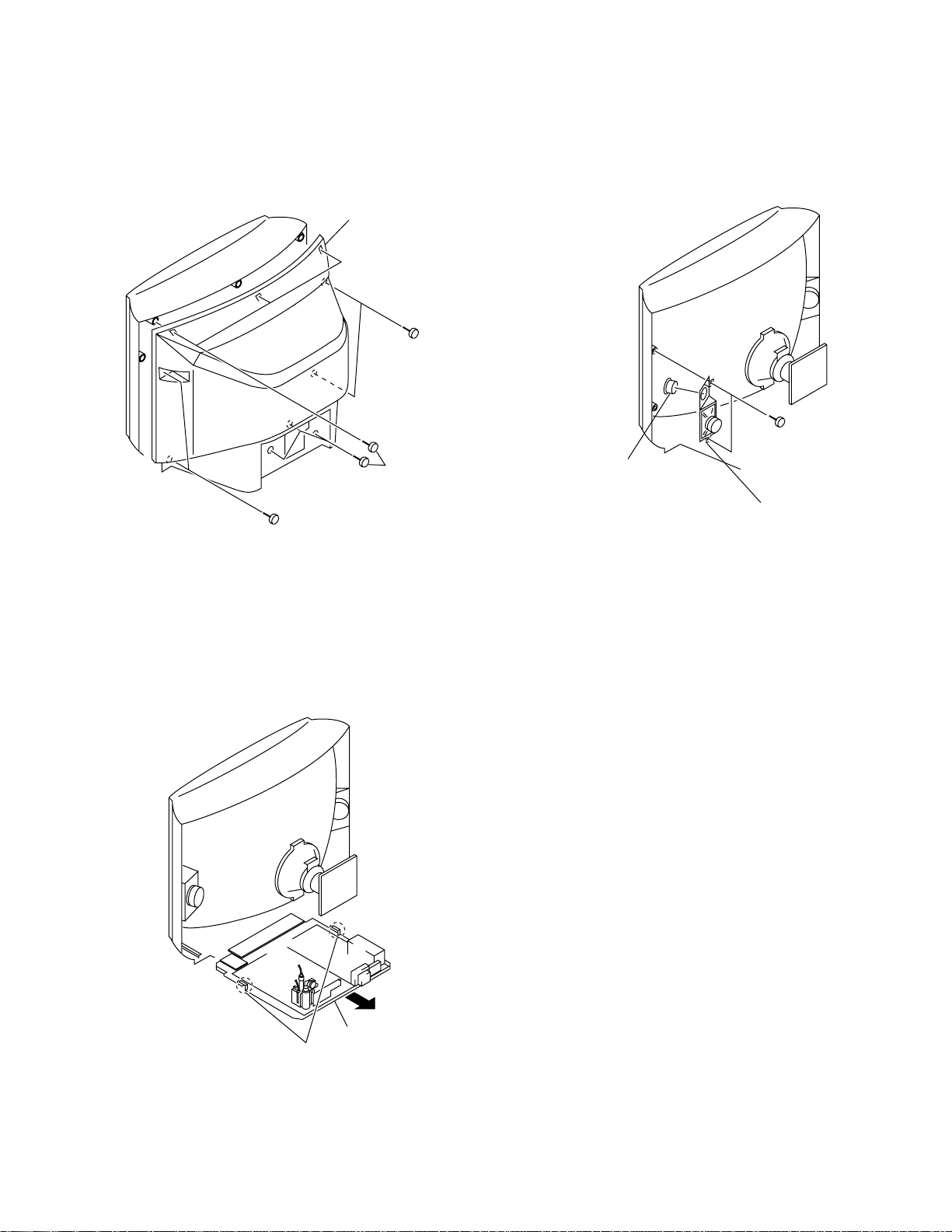
2-1. REAR COVER REMOVAL
1Two screws
(+BVTP4x16)
2 Rear cover
1Two screws
(+BVTP4x16)
1Six screws
(+BVTP4x16)
2-2. SPEAKER REMOVAL
3Speaker (5cm)
[KV-J29MF8J]
1Two screws
(+BVTP4 x16)
2Bracket (R) assy,sp
2-3. CHASSIS ASSY REMOVAL
1Two claws
2Chassis assy
– 11 –
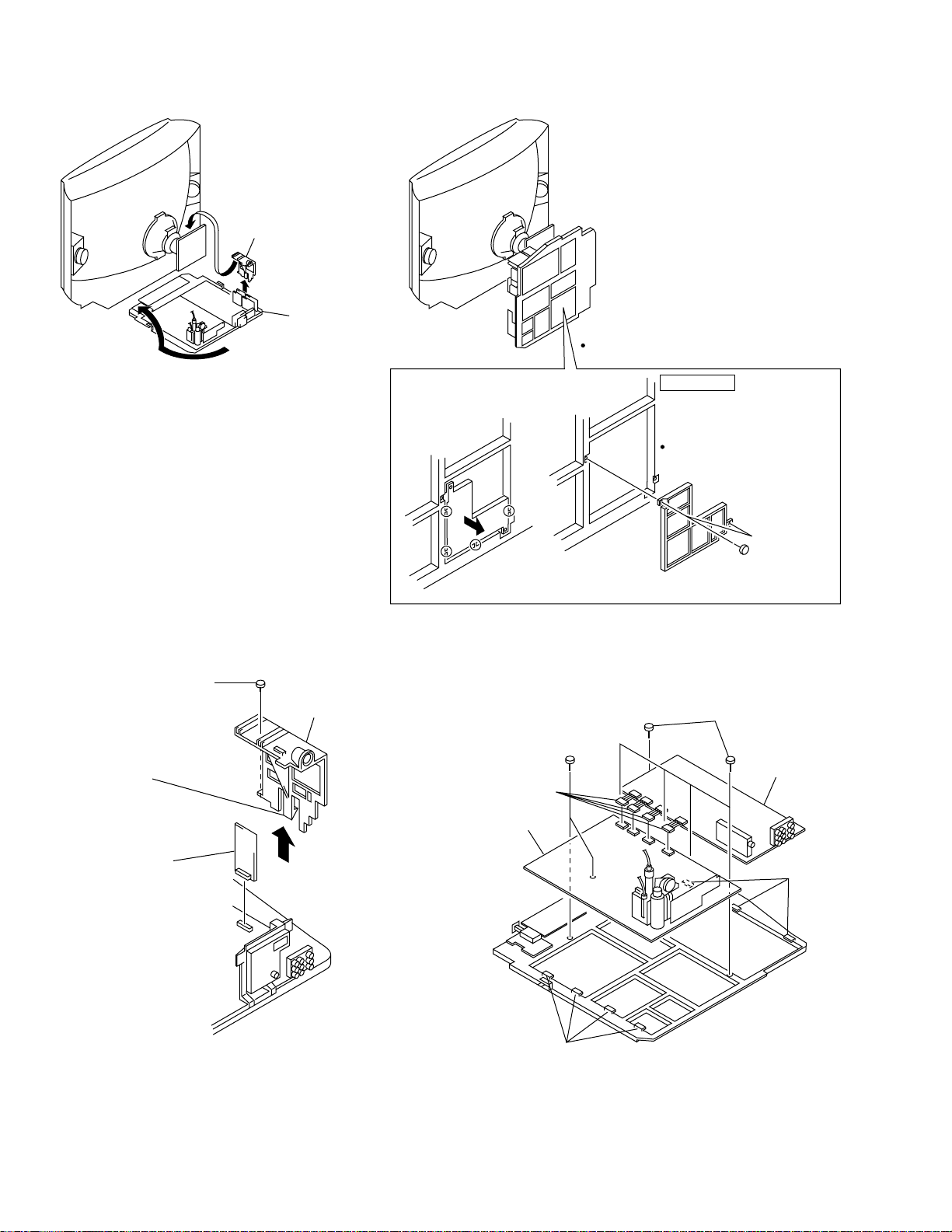
2-4. SERVICE POSITION
1PCB holder
2Chassis assy
Cut the four marked sections
1
with a nippers to remove a
part of bracket.
1
When measuring the power supply voltage,
just remove a part of bracket shown below.
ATTENTION
For safety reason this plate
2
must be remounted after
cutting and taking away.
SAFETY REQUIREMENT
2 Two screws
(+BVTP3 x 8)
(7-685-646-71)
2-5. S1 BOARD REMOVAL
1 Screw
(+BVTP3x12)
2 One claw
4 S1 Board
3 PCB holder
2-6. A AND D BOARDS REMOVAL
2 Five screws
(+BVTP3 x12)
5 Two screws
(+BVTP3 x12)
1 Four
connectors
7 D board
6 Four claws
4 A Board
3 Three
claws
– 12 –
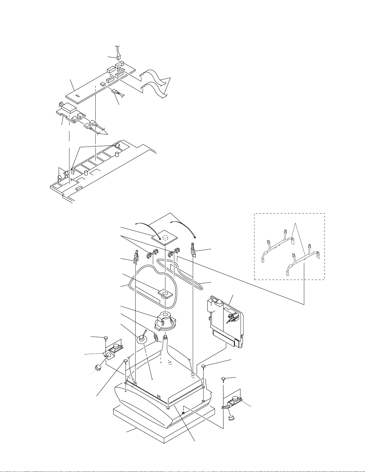
2-7. F1 AND H3 BOARDS REMOVAL
5 connector
8 H3 Board
6 connector
3 F1 Board
1 Two connector
7 Two claws
2 Two
claws
4 Two Flat
cables
2-8. PICTURE TUBE REOVAL
6 C2 Board
0 Two DGC holder
[KV-J29MF8J]
! DGC clip
7 Neck assy
@ DGC
8 Deflection yoke
# Tension spring
4 Anode cap
1 Two screws
(+BVTP4 x16)
2 Speaker
bracket(L)assy
3 Speaker (5cm)
[KV-J29MF8J ]
$ Two screws
(Tapping 7+Crown
Washer)
Cushion
9 Two DGC band
% Picture tube
[KV-J25MF8J]
0 Two DGC holder
! DGC clip
[KV-J29MF8J]
@ DGC
5 Chassis assy
$ Two screws
(Tapping 7+Crown
Washer)
1 Two screws
(+BVTP4 x16)
2 Speaker
bracket(R)assy
3 Speaker (5cm)
[KV-J29MF8J]
– 13 –
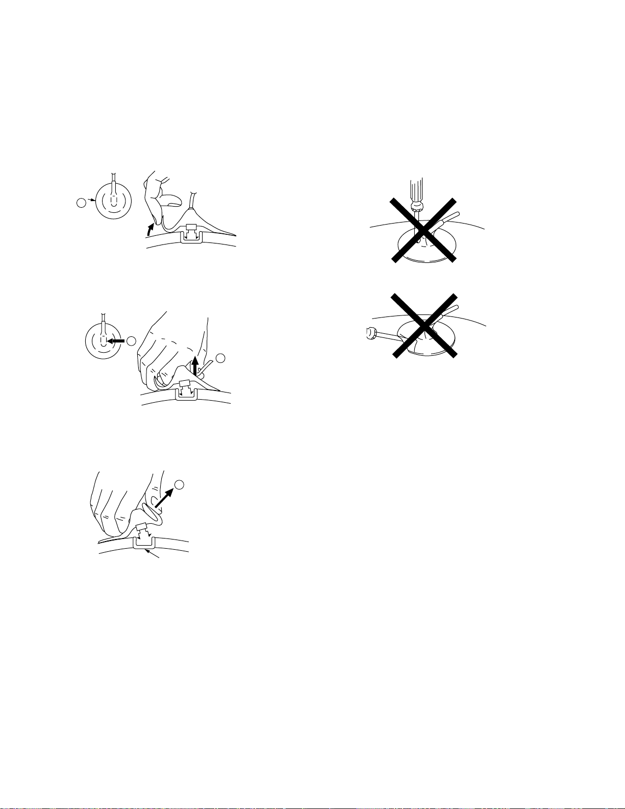
• REMOVAL OF ANODE-CAP
a
b
b
c
NOTE : Short circuit the anode of the picture tube and the anode cap
to the metal chassis, CRT shield or carbon paint on the CRT,
after removing the anode.
• REMOVING PROCEDURES
1 Turn up one side of the rubber cap in the direction
indicated by the arrow a.
• HOW TO HANDLE AN ANODE-CAP
1 Don't hurt the surface of anode-caps with sharp shaped
material!
2 Don't press the rubber hardly not to hurt inside of anode-
caps! A material fitting called as shatter-hook terminal
is built in the rubber.
3 Don't turn the foot of rubber over hardly! The shatter-
hook terminal will stick out or hurt the rubber.
2 Using a thumb pull up the rubber cap firmly in the direction
indicated by the arrow b.
Anode button
3 When one side of the rubber cap is separated from the
anode button, the anode-cap can be removed by turning
up the rubber cap and pulling up it in the direction of the
arrow c.
– 14 –
SECTION 3
SET-UP ADJUSTMENTS
• The following adjustments should be made when a complete
realignment is required or a new picture tube is installed.
• These adjustments should be performed with rated power
supply voltage unless otherwise noted.
Controls and switch should be set as follows unless otherwise noted:
PICTURE control.......................................................... RESET
BRIGHTNESS control............................................... CENTER
.................................................................................................................................................................................................................................
Preparations :
• In order to reduce the influence of geomagnetism on the set's
picture tube, face it east or west.
• Switch on the set's power and degauss with the degausser.
Perform the adjustments in order as follows :
1. Beam Landing
2. Convergence
3. Focus
4. White Balance
Note : Test Equipment Required.
1. Color-bar/Pattern Generator
2. Degausser
3. Oscilloscope
Neck assy
Behind the G1 edge
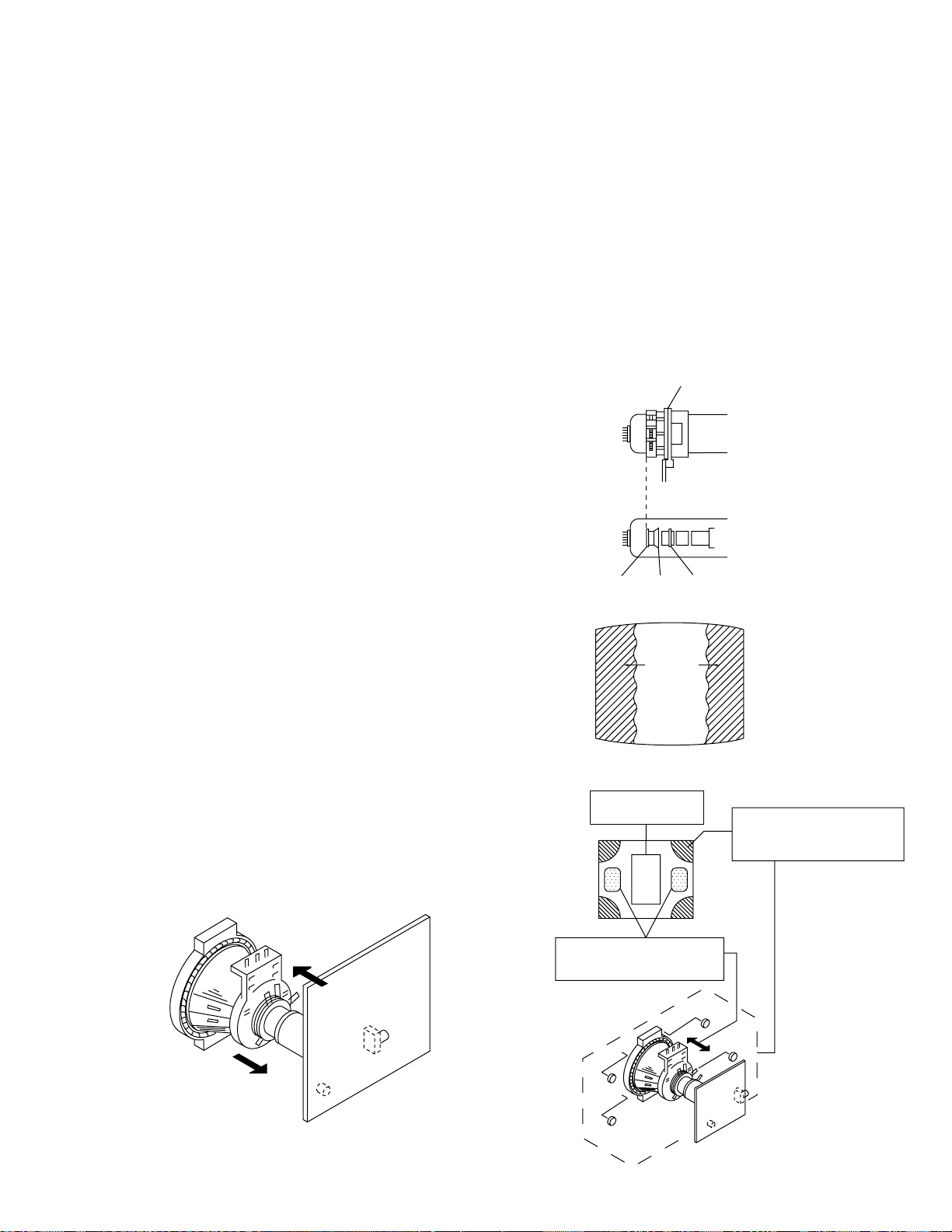
3-1. BEAM LANDING
1. Input a white signal with the pattern generator.
Contrast
Brightness
2. Position neck ass'y as shown in Fig3-2.
3. Set the pattern generator raster signal to a red raster.
4. Move the deflection yoke to the rear and adjust with the purity
control so that the red is at the center and the blue and the green
take up equally sized areas on each side.
(See Figures 3-1 through 3-3.)
5. Move the deflection yoke forward and adjust so that the entire
screen is red. (See Figure 3-1.)
6. Switch the raster signal to blue, then to green and verify the
condition.
7. When the position of the deflection yoke has been decided,
fasten the deflection yoke with the screws and DY spacers.
8. If the beam does not land correctly in all the corners, use a
magnet to adjust it.
(See Figure 3-4.)
}
normal
G2G1 G3
Blue
Green
Red
Purity control
corrects this area.
ab
Fig. 3-2
Fig. 3-3
Disk magnets or rotatable
disk magnets correct these
areas (a-b).
Fig. 3-1
– 15 –
c
Deflection yoke positioning
corrects these areas.
a
d
d
b
c
Fig. 3-4
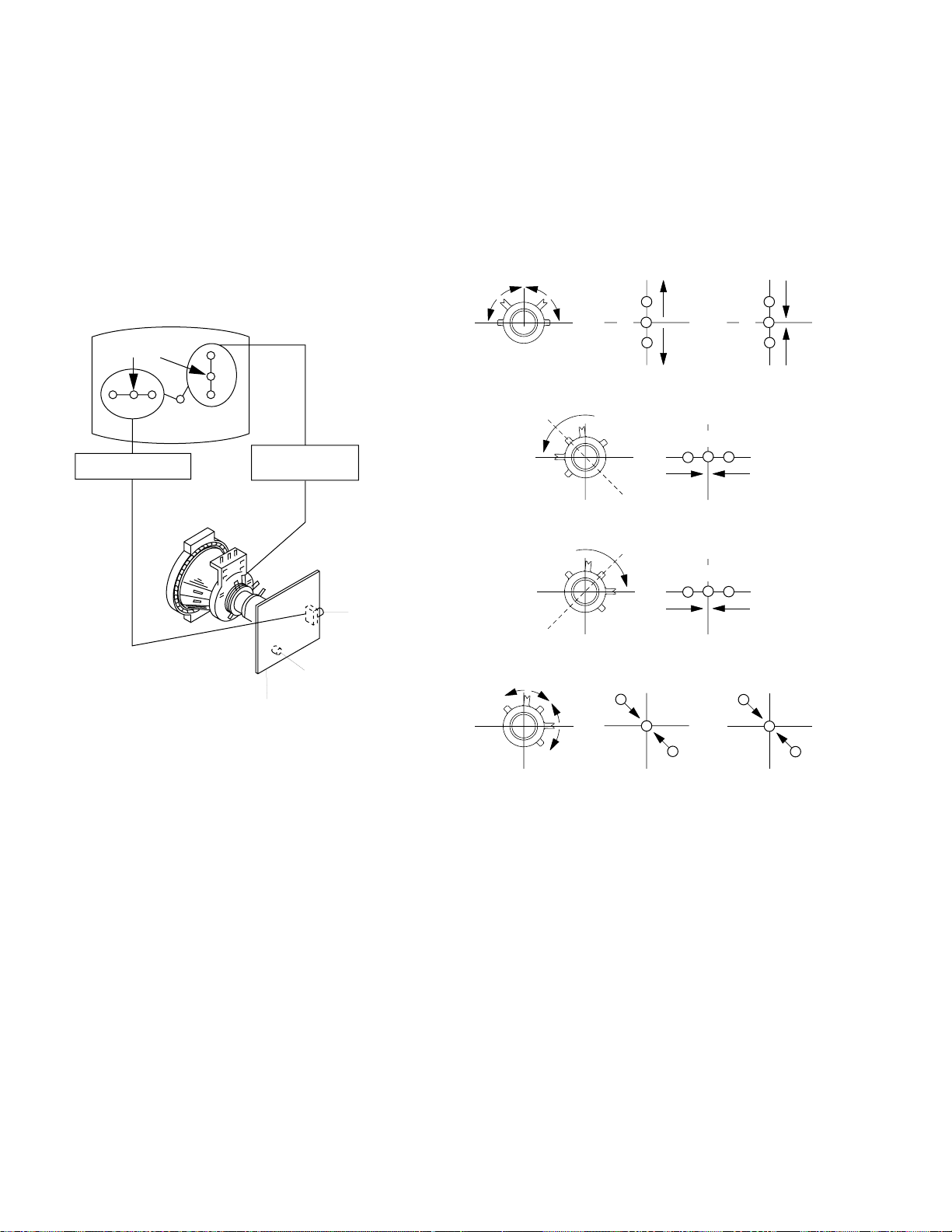
3-2. CONVERGENCE
Preparations :
• Before starting this adjustment, adjust the focus, horizontal size
and vertical size.
• Minimize the brightness setting.
• Provide dot pattern.
(1) Horizontal and Vertical Static Convergence
Center dot
R G B
H. STAT
R
G
B
V. STAT
Magnet
• Tilt the V.STAT magnet and adjust the static convergence by
opening or closing the V.STAT magnet.
If the V.STAT magnet is moved in the direction of the a and
b arrows, the red, green, and blue points move as shown
below.
1
2
a
bb
a
ab
B
GG
R
R G B
B
R
a
RV702
H. STAT
RV701
SCREEN (G2)
C Board
1. (Moving horizontally), adjust the H.STAT control so that the
red, green and blue points are on top of each other at the center
of the screen.
2. (Moving vertically), adjust the V.ST AT magnet so that the red,
green and blue points are on top of each other at the center of
the screen.
3. If the H.STAT variable resistor cannot bring the red, green and
blue points together at the center of the screen, adjust the horizontal convergence with the H.STAT variable resistor and the
V.STAT magnet in the manner given below.
(In this case, the H.STAT variable resistor and the V.STAT
magnet influence each other.)
b
3
b
a
b
a
R
G
B G R
B
b
b
B
G
R
– 16 –

• Operation of BMC (Hexapole) Magnet
If the red, green and blue dots are not balanced or aligned, then
use the BMC magnet to adjust in the manner described below .
RG B
RGB R GB
• Use the H.STAT VR to adjust the red, green, and blue dots so
that they coincide at the center of screen.
The respective dot position resulting from moving each
magnet interact, so be sure to perform adjustment while
tracking.
R
B
G
RGB
G
R
B
1 Y separation axis correction magnet adjustment receive the
cross-hatch signal and adjust [PICTURE] to [MIN] and
[BRIGHTNESS] to [STANDARD] .
2 Adjust the Y separation axis correction magnet on the neck
assembly so that the horizontal lines at the top and bottom of
the screen are straight.
BLUE Paint
VM Board
VM Board
RED Paint
RED Paint
BLUE Paint
Note 1) The Red and Blue magnets should be equally far from
the horizontal center line.
2) Do not seperate the Red and Blue magnets too far.
(Less than 8 mm)
– 17 –

(2) Dynamic Convergence Adjustment
Preparation:
• Before starting this adjustment, adjust the horizontal static
convergence and the vertical static convergence
1. Slightly loosen the deflection yoke screws.
2. Remove the deflection yoke spacer.
3. Move the deflection yoke as shown in the figure below and
optimize the convergence.
4. Tighten the deflection yoke screws.
5. Install the deflection yoke spacer.
R G B B G R
R
B G R
G
R G B
B
B
R G B
G
B G R
R
B
G
R
B G R R G B
R
G
B
(3) Screen-corner Convergence
b
a-b:scrren-corner
misconvergence
c
Affix a Permalloy assy corresponding to the misconverged
a
d
areas.
a
d
Permalloy assembly
b
c
– 18 –

3-3. FOCUS ADJUSTMENT
Adjust FOCUS control on the flyback transformer for the best
focus.
Focus
d. MEMORY WRITE CONFIRMATION METHOD
1) After adjustment, pull out the plug from AC outlet, and then
plug into AC outlet again.
2) Turn the power switch ON and set to Service Mode.
3) Call the adjusted items again to confirm adjustments were made.
DATA
SERVICE
07
LCP
09
Adjustment Item
Item number
FLYBACK TRANSFORMER (T801)
a. AN ITEM OF ADJUSTMENT
Adjustment
Item
number
37
item
SBR
Standard DA TA
1F
Note
SUBBRIGHTNESS
39
3A
3B
3C
GDR
BDR
GCF
BCF
2C
2C
07
07
G. Drive
B. Drive
G. CUT-OFF
B. CUT-OFF
b. METHOD OF CANCELLATION FROM SERVICE
MODE
Set the standby condition (Press POWER button on the
commander), then press POWER button again, hereupon it becomes TV mode.
c. METHOD OF WRITE FOR MEMORY
1) Set to Service Mode.
2) Press 1 (UP) and 4 (DOWN), select an item of adjustments.
3) Press MUTING button indicate WRITE (RED) on screen.
4) Press `º button to write into memory.
WRITE07LCP09
MUTING
0
Executes the writing
– 19 –
3-4. G2 (SCREEN) AND WHITE BALANCE
ADJUSTMENTS
1. G2 (SCREEN) ADJUSTMENT (RV701)
1) Set the PICTURE and BRIGHTNESS to normal.
2) Put to VIDEO input mode without signals.
3) Set to Service Mode.
4) Change BLU data of the item number 8C from 01 to 00 .
(To turn off Blue Back.)
5) Press MUTING , and `0 to write the data in the memory.
6) Connect R, G, and B of the C board cathode to the oscilloscope.
7) Adjust G2 (RV701) volume to the value below.
170V ±2(VDC)
170 V ±2(VDC)
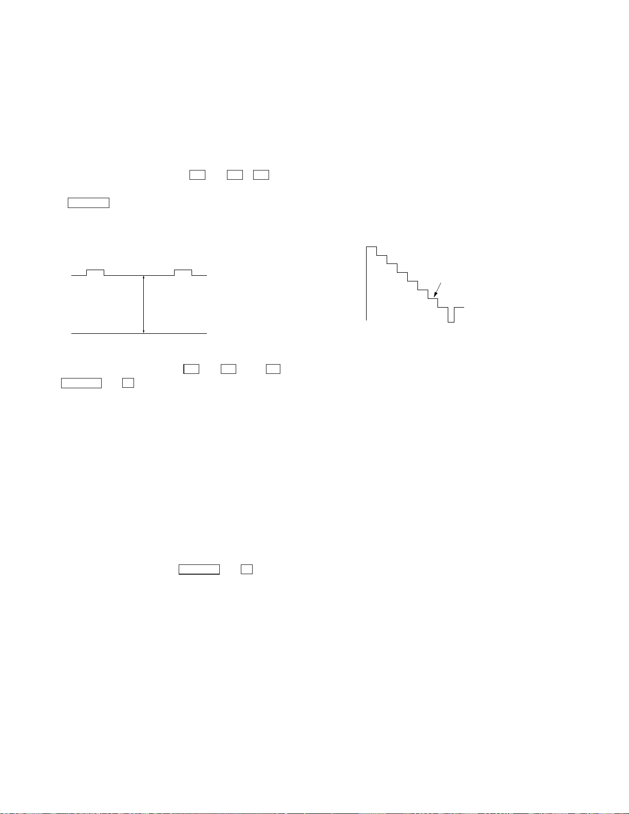
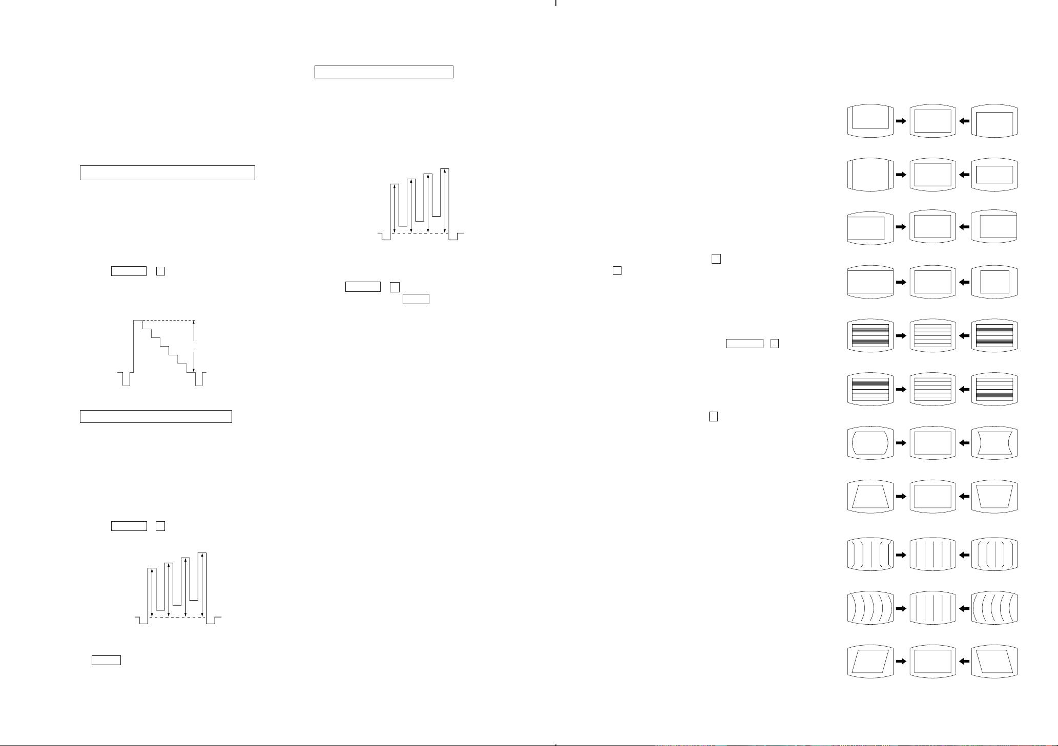
3. SUB BRIGHT ADJUSTMENT
1) Set to service mode.
2) Input a staircase signal of black and white from the pattern
generator.
3) BRIGHTNESS .... RESET.
PICTURE ............ minimum
4) Select SBR(55) with 1 and 4 , and adjust SBR level with
3 and 6 so that the stripe second from the right is dimly lit.
White
second from the right
0V
8) Re-set BLU data of the item number 8C from 00 back to 01
9) Press MUTING , and 0 to write the data in the memory.
2. WHITE BALANCE ADJUSTMENTS
1) Set to service Mode.
2) Input white raster signal.
3) Set the PICTURE to minimum.
4) Select SBR(35) with 1 and 4 , and then set the level to
minimum with 3 and 6 .
5) Select GCF(39) and BCF(3A) with 1 and 4. And adjust
the level with 3 and 6 for the best white balance.
6) Set the PICTURE to maximum.
7) Select GDR(37) and BDR (38) with 1 and 4, and adjust the
level with 3 and 6 for the best white balance.
8) Write into the memory by pressing MUTING then 0 .
Black
.
– 20 –

SECTION 4
SELF DIA GNOSIS FUNCTION
If no acknowledgement is returned from a device which is turned "ON", the device has a problem.
In this case, one of the LED's responding to the problem device will flicker a defined number of times.
The flickering frequuncy responding to each failed device is shown below.
Board name A Board A Board A Board A Board
Ref. No IC003 IC1201 IC104 IC206
Device NONVOLA- AV SWITCH MAIN Y/C AUDIO
TILE (CXA1855S) (CXA2050S) PROCESSOR
MEMORY (TDA8424)
Flickering
Frequency
All the device are checked one after another from the left on the table.
If an error is found, the responding LED will start flickering.
So, if more than 2 device are failed, the one on the left side will start flickering first.
1236
– 21 –

SECTION 5
CIRCUIT ADJUSTMENTS
5-1. ADJUSTMENTS WITH COMMANDER
Service adjustments are made with the RM-871 that comes with
this unit.
Entering service mode
With the unit on standby
↓
DISPLAY
↓
5
↓
VOL (+)
↓
POWER
The operation sequence puts the unit into service mode.
1, 4 Select the adjustment item.
↓
3, 6 Raise/lower the data value.
↓
MUTING Writes.
↓
0 Executes the writing.
7, 0 All the data becomes the values in memory.
8, 0 All user control goes to the standard state.
5, 0 Service data initialization (Be sure not to use
usually.)
2, 0 Write 50Hz adjustment data to 60Hz, or vice
versa.
The screen display is :
DISPLAY
REVEAL
MUTING
TEXT
123
456
789
A/B
ENLARGE
WAKE UP
INDEX
SLEEP
TEXT CLR
R
RM-873
VIDEO
HOLD
0
POWER
MENU
MENU
PROGRVOL
RM-873
JUMP
Adjstment item
TV
Item number
DATA
00 VSH 1F SERVICE 50
XXX 00 00 00 20V2 1C
Mode
Depends on the signals
PAL, SECAM : 50
NTSC : 60
SOFTWAR VERSION
H SYNC COUNTEROEM CODE
– 22 –

5-2. ADJUSTMENT METHOD
Item Number 00
This explanation uses V-Position as an example.
1. Select 00 VSH with the 1 and 4 buttons.
2. Raise/lower the data with the 3 and 6 buttons.
3. Select the optimum state. (The standard is IF for P AL reception.)
4. Write with the MUTING button. (The display changes to
WRITE.)
5. Execute the writing with the 0 button. (The WRITE
display will be changed back to SERVICE.)
Use the same method for Items Number 00-96. Use 1 and 4 to
select the adjustment item, use 3 and 6 to adjust, write with
MUTING , then execute the write with 0 .
Note : In WRITE , the data of all items are into memory.
• As for V-FREQ, by searching the bolded screen V range with
adjusting data.
Note : For adjustment Items that have differnt standard data
between 50Hz or 60Hz and novwel or wid, be sure to use
the respective input signal ather adjusting.
1FVSF00
SERVICE 50
WRITE 50
WRITE 50
00
Adjusted with [3] and [6] buttons
Written with [MUTING]
GREEN1FVSF
GREEN1FVSF00
GREEN
The WRITE display
then the display
returns to a green
SERVICE.
Write executed with [0]
– 23 –

Adjustment Item Table
Item Adjustment Data
number Item range
00 VSH 00-3F 1F V Position CXA2050S
01 VSZ 00-3F 1F V Size (Y/C/J)
02 HSH 00-0F 07 H Position Slv:88H
03 HSZ 00-3F 1F H Size
04 SRC 00-0F 07 S Correction
05 VLN 00-0F 07 V Linearity
06 PAP 00-3F 1F Pin Comp
07 PPH 00-0F 07 Pin Phase
08 UCP 00-0F 07 Up Corner Pin
09 LCP 00-0F 07 Low Corner Pin
0A BOW 00-0F 07 AFC-Bow
0B ANG 00-0F 07 AFC-Angle
0C VAP 00-3F 2F V Aspect
0D VSC 00-3F 1F V Scroll
0E ULN 00-0F 00 UP V Linearity
0F LLN 00-0F 00 LOW V Linearity
10 EHH 00-03 01 00 EHT- H
11 EHV 00-03 01 EHT - V
12 HBS 00-01 01 H Blk Wid. ON/OFF
13 LBK 00-0F 0F L Blk Width
14 RBK 00-0F 0F R Blk Width
15 JSW 00-01 00 Jump ON/OFF Sw
16 VBW 00-03 02 V Blk Wid. Con.
17 AFC 00-03 01 AFC-Mode
18 FHH 00-01 00 FH-HI
19 VFQ 00-03 00 V-Freq
1A VOF 00-01 00 V OFF
1B VMD 00-01 00 CD-Mode 2
1C CMD 00-01 00 CD-Mode
1D ITL 00-03 00 Inter Iace
1E ZSW 00-01 00 ZOOM SW
1F POV 00-03 03 Pre-Over
20 CT1 00-01 01 C-Trap(NTSC)
21 CT2 00-01 00 C-Trap(PAL)
22 CF0 00-0F 00 C-Trap f0 Adj
23 SF0 00-01 00 01 Sharpness f0 Adi
24 TOT 00-01 01 TOT Filter SW
25 CSW 00-03 00 Color SW
26 XTL 00-03 00 Xtal
27 CV1 00-01 01 CV/YC Select(NTSC)
28 CV2 00-01 00 CV/YC Select(PAL)
29 VM 00-01 01 VM ON/OFF
2A YVM 00-01 00 YSI/VM SW(0:YSI)
2B DPC 00-01 01 D-Pic ON/OFF
2C DCO 00-01 01 Dynamic Color
2D GMM 00-03 01 Gamma
2E DTR 00-01 01 DC-Tran
2F DL1 00-07 01 Delay Ctrl.(PAL)
30 DL2 00-07 03 Delay Ctrl.(NTSC)
31 DL3 00-07 03 Delay Ctrl.(SECAM)
32 SCN 00-0F 09 Sub-Contrast
33 SC1 00-0F 07 Sub-Color(PAL)
34 SC2 00-0F 06 Sub-Color(NTSC)
35 SH1 00-0F 07 Sub-Hue(TV)
36 SH2 00-0F 07 Sub-Hue(VIDEO)
37 SBR 00-3F 1F Sub-Bright
38 SSH 00-07 04 04 Sub-Sharpness
39 GDR 00-3F 2C G-Drive
Standard data
J29 J25
Note Device
Note: Bold items are fixed data.
: NTSC , NO MARK : PAL
*
– 24 –

Adjustment Item Table
Item Adjustment Data
number Item range
3A BDR 00-3F 2C B-Drive CXA2050S
3B GCF 00-0F 07 G-Cutoff (Y/C/J)
3C BCF 00-0F 07 B-Cutoff Slv:88H
3D RPO 00-03 01 Ref-Position
3E PON 00-01 01 Pic-ON
3F RON 00-01 01 R ON
40 GON 00-01 01 G ON
41 BON 00-01 01 B ON
42 AKF 00-01 00
43 ESY 00-01 00
44 AGG 00-01 00
45 ABL 00-01 00 Picture Booster
46 LIM 00-01 00 Black Offset
47 PB 00-01 00 Picture Booster TDA9170
48 BOF 00-00 00 Black Offset (Picture
49 UVG 00-3F 00 User Var Gamma Improve)
4A ADG 00-3F 00 Adaptive Gamma Slv:D0H
4B NLA 00-3F 00 Non-linear Amp
4C WDS 00-02 00 Window Select
4D LST 00-0F 00 Window Line Start
4E LSP 00-0F 00 Window Line Stop
4F FST 00-0F 00 Window Field Start
50 FSP 00-0F 00 Window Field Stop
51 VA 00-01 00 V Aperture on/off CXA1315
52 VAW 00-03 00 V Aperture white (V-AP)
53 VAB 00-03 00 V Aperture black Slv:48H
54 VAC 00-0F 00 V Aperture core
55 SHP 00-3F 00 Sharpness CXA1315
56 VML 00-3F 00 VM mitter (LTI)
57 COR 00-3F 00 Conng Slv:42H
58 DOF 00-3F 00 DSC Offset
59 DGA 00-3F 00 DSC Gain
5A DLT 00-01 00 Delay Time
5B SDL 00-0F 00 SEL Pin Delay SDA9189X
5C POH 00-FF 00 H Position(MSB 8bit) (PinP)
5D POV 00-FF 00 V Position Slv:D6H
5E PMD 00-1F 00 PinP Display Mode
5F WRP 00-0F 00 Write Position
60 HDL 00-1F 00 HS Delay
61 AMS 00-01 00 Decimation Filter
62 VDL 00-1F 00 VS Delay
63 VSP 00-1F 00 VSP Delay
64 CON 00-0F 00 Contrast
65 FRY 00-0F 00 Frame Y
66 FRV 00-0F 00 Frame V
67 FRU 00-0F 00 Frame U
68 INF 00-01 00 Inner Frame
69 FWV 00-03 00 Frame Width V
6A FWH 00-07 00 Frame Width H
6B PLL 00-03 00 PLL Loop Filter
6C PDV 00-0F 00 Pedestal V
6D PDU 00-0F 00 Pedestal U
6E DAT 00-01 00 DAC Stream Control
6F DAN 00-01 00 DAC Control
Standard data
J29 J25
Note Device
Note: Bold items are fixed data.
– 25 –

Adjustment Item Table
Item Adjustment Data
number Item range
70 WIP 00-01 00 Wipe on/off SDA9189X
71 WSP 00-03 00 Wipe Speed (PinP)
72 FAW 00-FF 08 NICAM FAW Thresh MSP3410
73 CTM 00-FF 08 NICAM Error Bit(MONO) (Stereo Decoder)
74 CTN 00-FF 50 NICAM Error Bit(NICAM) Slv:80H
75 WCD 00-FF 0A W.G.DA T A CHANGE
76 WST 00-FF 15 W.G.STEREO Threshold
77 WTM 00-FF 50 W.G.Timer
78 WBT 00-01 EA W .G.bilingual Threshold
79 ACG 00-01 01 AGC AUTO/CONST
7A CDB 00-3F 28 AGC GAIN CONST.
7B FGP 00-7F 24 FM(BG,I,DK)Prescale
7C FMP 00-7F 40 FM(M)Prescale
7D WGP 00-7F 3C W.G.Prescale
7E NIP 00-7F 7F NICAM Prescale
7F CRM 00-01 00 Carrier Mute
80 CML 00-03 00 Carrier Mute Level
81 ACO 00-01 01 Audio Clock Out
82 WAC 00-0F 01 W.G.Agreement count
83 DL Y 00-FF 30 Stereo Search Delay
84 DLG 00-FF 10 W.G.Search Delay
85 TXP 00-0F 0E Text Picture cont. SAA 5281
86 MXP 00-0F 0F Text Mix Mode Pic (Text decoder)
87 BB1 00-3F 00 BBE control High CXA1315
88 BB2 00-3F 1D BBE control Middle (BBE)
89 BB3 00-3F 28 BBE control Low Slv:40H
8A ATW 00-03 00 Auto Wide Ident speed CXP5068
8B BKP 00-FF 00 Blk off Picture CXP85340
8C OSH 00-3F 0E OSD Position H (MICRO8D ODL 00-FF 10 Power On Delay CONTROLLER)
8E BLU 00-01 01 Blue Back on/off
8F ROC 00-0F 08 N/S Center Vol.
90 ROS 00-07 07 User Step
91 DKS 00-01 00 D/K Stereo Serch
92 MUT 00-01 01 No.Sync.Mute
93 DID 00-01 00 Disable Degauss
94 DWZ 00-01 00 Disable Widezoom
95 BCS 00-01 00 BASS Center Shift
96 BVS 00-01 00 BASS Volume Shift
97 WBS 00-03 01 Woofer off Bass Shift
98 OPO 00-FF 01 Option 0
99 OP1 00-FF 32 02 Option 1
Standard data
J29 J25
Note Device
Slv:D6H
Slv:58H
(Auto wide)
Note: Bold items are fixed data.
ITEM INFORMATION
...
• 50
50Hz data, 60
• Standard data listed on the Adjustment Item Table are reference values, therefore if is different for every model.
...
60Hz data
– 26 –
5-3. PICTURE QUALITY ADJUSTMENTS
Item Number 33-36
33 SCO Sub-Color
34 SHU Sub-Hue
35 SBR Sub-Bright
5-4. A BOARD ADJUSTMENT
SUB CONTRAST ADJUSTMENT (SCN)
1. Receive a PAL color-bar.
2. Set service item 3E GON and 3F BON to data "00". Set the
PICTURE 100%, BRIGHT 50% and COLOR MIN.
3. Connect an oscilloscope to the pin 6 (R OUT) of CN117, A
board.
4. Set to Service Mode and select 32 (SCN) using 1 and 4 of
the commander to adjust to 2.10 ± 0.05V.
5. Press MUTING → 0 of the commander to write the data.
6. Receive a NTSC color-bar and adjust 32 (SCN) as step 2~5.
7. Set servce item 3E GON and 3F Bon to data "01".
white
2.45 ± 0.05 Vp-p
black
SUB COLOR ADJUSTMENT (SCO)
1. select Video1
2. Input a PAL color-bar, video into video1.
Set to the following condition:
PIC 100%, BRT 50%, COL 50%
3. Connect an oscilloscope to the pin 5 (B OUT) of CN117, A
board.
4. Set to Service Mode and select 33 (SCO) with 1 and 4 of
the commander to adjust to VB2=VB3=VB4 with 3 and 6.
5. Press MUTING → 0 of the commander to write the data.
6. Adjust 33 (SCO) as step 1~4.
SUB HUE ADJUSTMENT (SHU)
1. select Video1
2. Input a NTSC color-bar, video into video1.
3. Connect an oscilloscope to the pin 4 (B OUT) of CN117, A
board.
4. Select 34 (SHU) with 1 and 4 of the commandar by setting
to Service Mode and adjust to VB1=VB2=VB3=VB4 with 3
and 6.
VB1 VB2 VB3 VB4
VB2 = VB3 = VB4
5. Press MUTING → 0 of the commander to write the data.
6. Set to WIDE Mode by MENU button to write the same value
as in step 3.
PIP POSITION (POH, POV)
1. Receive a PAL color-bar.
2. Set the PIP picture by pressing PIP button of the commander.
3. Set to Service Mode.
4. Select 5A (POH) with the 1and 4of the commander to set
the data "14" with 3and 6.
5. Select 5B (POV) to set the data "27"
6. Press MUTING → 0 of the commander to write the data.
7. Check by changing using menu .
5-5. A BOARD ADJUSTMENT AFTER IC003
(MEMORY) REPLACEMENT
When replacing IC003(MEMORY) be sure to change IC001(µ-COM)
to the following new IC at the same time.
IC001 (µ-COM)
• GE, EM, E, HK model
CXP85340A-072S to CXP85340A-099S (8-752-880-11)
• ME (Arabic) model
CXP85340A-084S to CXP85340A-098S (8-752-879-23)
1. Enter to Service Mode.
2. Press commander buttons 5 and 0 (Data Initialize), and 2
and 0 (Data Copy) to initialize the data.
3. Call each item number, and check if the respective screen shows
the normal picture.
In cases where items are not well adjusted, rectify the items
with fine adjustment.
Write the data per each item number ( MUTING + 0 ).
4. Select item numbers “95” (OP0) and “96” (OP1) and
respectively set the bit per model with command buttons 3
and 6.
5. Press commander buttons 8 and 0 (Test Normal) to return to
the data that was set on the shipment from the factory.
(This will also cancel Service Mode.)
5-6. PICTURE DISTORTION ADJUSTMENT
Item Number 00 – 0B
00 VSH(V POSITION)
01 VSZ(V SIZE)
02 HSH(H POSITION)
03 HSZ (H SIZE)
04 SCR(VERTICAL Scorrection)
05 VLN(V LINEARITY)
06 PAP (PIN AMP)
07 PPH(PIN PHASE)
08 UCP(Upper Corner Pin)
09 LCP(Lower Corner Pin)
VB1 VB2 VB3 VB4
VB2 = VB3 = VB4
7. Receive the NTSC color-bar and adjust as step 6.
–27–
0A VBOW(AFC.BOW)
0B VAG(AFC.ANGLE)
– 28 –
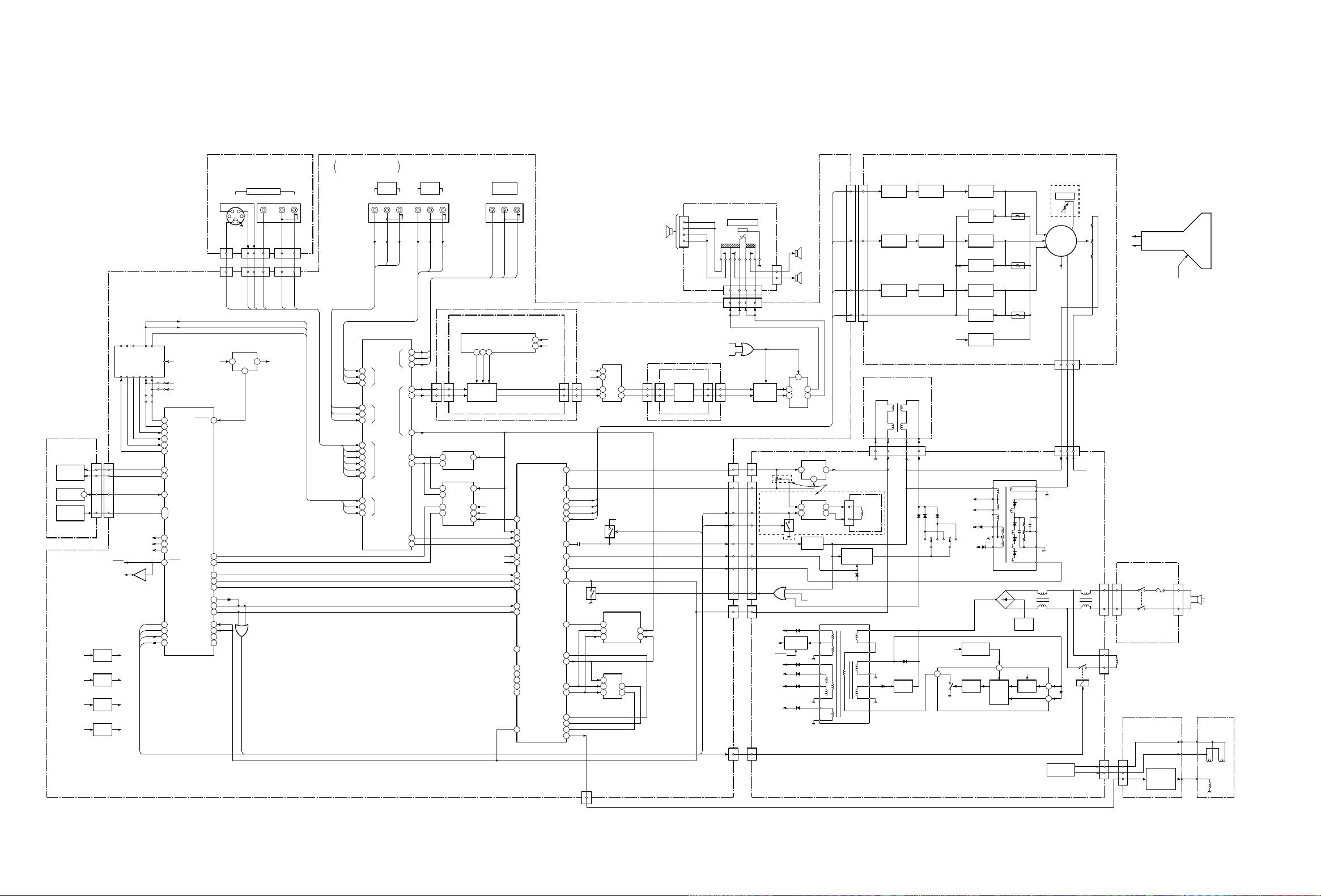
6-1. BLOCK DIAGRAM
IF
SFI
DET
MS IF
H3(1/3)
(CONTROL SW.)
RED/
GREEN LED
D904
SIRCS
IC900
KEY-IN
MATRIX
S901-910
+11V
TU001
TUNER
CN103CN905
6
10
4
12
2
14
1
1, 3
13
STBY
REG
IC080
REG
IC201
REG
IC205
REG
+7V
IC010
RED
GREEN
+12VAUDIO 30V
DE EM
NC
RF
AFT
SW2
SW1
SCL
SDA
MUTE
SCL
SDA
Q033
MUTE
+5V+9V
+9V
+5V
H3(2/3)
(AV INPUT)
VIDEO 3 INPUT
S
43
J902
21
CN905
15
CN103 CN102 CN103
MUTE STBY 5V
BACK UP
SCL
SDA
TUNING CONTROLLER
IC001
BAND0
RESET
58
57
7
8
40
9
6
5
26
41
•
42
11
56
54
30STBY
16
27
31
60
BAND1
TSW0
TSWI
AFTI
AGC
NICAM
TIMER
SIRCS
KEY1, 2
MUTE
11 CLK0
11 DAT0
STBY
DEGAUSS
HD SW
NS MUTE
NS ROT
PAL/NT
H SYNC
H SYNC
V SYNC
V PULSE
36
3
THR
4
R
47
G
48
B
49
BLK
12
YS
51
YS
52
1
25
2
17
141
S3
REG
15
IC002
4
Q304
D303
V MUTE
VM MUTE
(FRONT)
CN901 CN905
141154122
L3
V3C3Y3
SECTION 6
DIAGRAMS
MAIN TUNER,VIF,SIF
A
AV SW Y/C DECODE JUNGLE
RLV
J903
4122
R3
LT
RT
VT
L1
R1
S1
V2
L2
R2
C3
Y3
V3
L3
R3
S3
VT
LT
RT
VLR
V2
2
L
4
R
6
S1
7
V
8
L
10
R
17
C
15
Y
13
V
14
L
16
R
18
S3
V
47
L
48
R
49
VIDEO
IN2
L2
A/V SELECT
IC1201
MON2
S1
MON1
S2
S3
TV
R2
J1202 RLV
V
L
R
L
R
V
Y
C
Y
C
VIDEO
IN1
L1
V1
VM
29
LM
28
RM
26
CN121 CN2201
39
38
40
37
35
43
45
R1
S1(1/2)
123
LR787
8
EQ. CHANGE
IC2211, 2212
Y/C SEP
YCM301
26
Y
V
4
C
Y/C SEP
IC301
Y
V
46
C
2
PAL/NT
13
18
THR
12
17
CLK
15
MONITOR
OUT
VM
(AUDIO EFFECT)
D/A CONVERTOR
SW1
SW0
DAC4
SCL
SDA
SCL
SDA
LM
IC2201
RM
6
60
62
64
56
57
23
24
25
21
22
58
63
18
19
20
17
36
J1202VLR
Y/C JUNGLE
FSC
V
Y
C
SCL
SDA
R2
G2
B2
YS2
VIDEO
EXT SYNC
R1
G1
B1
YS1
VTIM
1514SCL
SDA
IC104
AFCP IN/
SECAM
CN2201
VD-
VD+
E-W
ABL
H OFF
REF
SCP
B-Y
R-Y
YRET
B-Y
R-Y
VM
R
G
B
IK
HD
Y
101110
37
36
28
30
32
33
43
39
34
44
7
11
12
10
9
13
15
14
55
SCL
SDA
11
CN121
Q105
12
11
13
1
3
IC206
AUDIO PROCESSOR
STBY 5V
Q030
SECAM PROCESSOR
IC354
S REF
1
B-Y
12
R-Y
11
1H DELAY
IC351
SYNC
14512
16
11
CN120
H3(3/3)
4
3
OUT
WOOFER
CN128 CN128
232
9
SIN
20
SYNC
19
2
1
CN908
S1(2/2)
L
AMP
3
IC2213,
R
2214
CN2208 CN2208
HD SW
IN
CN901
CN102
161
NS ROT
NS MUTE
DEGUSS
HEAD PHONE
15 13 8 10
1386
MUTE
STBY
6
CN108
CN109
CN107
CN106
J901
Q211,D218
PROTECTOR
Q205, 210
D
2
2
CN506
8
8
9
3
3
7
7
4
4
1
1
CN520
2
2
CN528
22
4
1
Q1803
Q803,1501
+33V
STBY
+7V
+14V
+11V
SP R
SP L
11
MUTE
4
2
IC203
RIPPLE FILTER
1 5
6
3 1
H DRIVE
REG
Q601-603
7
12
V OUT
IC1501
IC1800
DRIVE
T2502
135V
CN902
MUTE
(POWER SUPPLY DEFLECTION)
CN526
ROTATION
E/W
ABL
X-RAY
BACK UP
AUDIO 30V
7
14
13
12
16
18
17
15
CN117 CN703
R
G
B
IK
29 inch ONLY
CN1804
7
T601
SRT
6
5
4
1
N/S COIL
PIN DRIVE
IC2504
T2503,2504
C2
6
5
4
1
DY ASS'Y
VM
(2/2)
(RGB OUT)
Q712
R DRIVE
Q711
G DRIVE
Q710
B DRIVE
V DV H DV
56 13
6
7
2
4
3
CLAMP
Q600
4
9
Q706
R AMP
Q705
G AMP
Q704
B AMP
+9V
S2501 S2502
+33V
1
SWITCHING REG
IC601
+200V
+135V
+15V
-15V
LEVEL DED
IC602,603
Q703
R OUT
Q709
IK LIMIT
Q702
G OUT
Q708
IK LIMIT
Q701
B OUT
Q707
IK LIMIT
Q714
BIAS
10
D2600
29 inch ONLY
RV702
H. STAT
J701
13
10
983
5
1
H1
FV
H1
+200V
+1000V
CN701
142
142
CN0521
H1
+1000V
T801
FBT
1
4
2
9
8
7
H1
5
H2
HV
DF
FV
11
ABL
+200V
F1
CN2600
1
T2602
PC SW
Q2601
7
REF
COMPOSCDRIVE
6
8
QP DRIVE
Q1804,1805
RV2600
11
5
5
1
3
CN518
3
QP-
QP+
2
VM OUT
H
(AC IN)
DGC
VM(1/2)
6
5
2
CN961
PICTURE
TUBE
HV.FV
(VM OUT)
VELOCITY
MOD
Q961-963
Q965,967,968
FROM FBT
4
QP-
QP+
VM
NECK
ASS'Y
QP QP
VM
– 29 – – 30 –
DY
VM
S1
A
D
TUNER
C2
F1
H3
OPEN
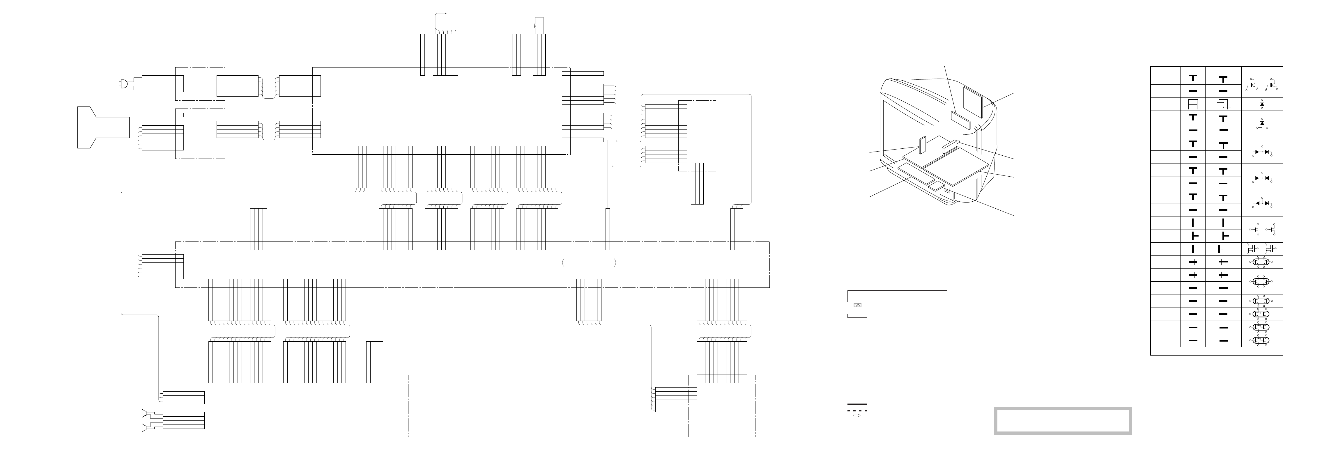
6-2. FRAME SCHEMATIC DIAGRAM
PICTURE
TUBE
CN1690 CN2600
CN704
CN703
CN117
1
2
3
4
1
1
2
3
4
5
6
1
2
3
4
5
6
F1
(AC IN)
C2
(RGB OUT)
CN102
AC
NC
NC
AC
GND
1K
GND
9V
B
G
R
1K
GND
9V
B OUT
G OUT
R OUT
CN1691
AC OUT
1
2
3
4
5
1
2
3
4
123456789
SP L
SP L
PH L
CN701
SP GND
SP GND
SP R
NC
NC
NC
AC OUT
1000V
200V
E
H1
SP R
PH R
GND
CN118
123
1011121314
GND
SP GND
SP GND
OPEN
B INT
B CLK
B DAT
4
GND
FR Y OUT
FR C OUT
15
CN103
FR V OUT
123456789
S3
AC IN
NC
NC
NC
AC IN
1000V
200V
GND
H1
GND
FR L OUT
CN0521
GND
GND
FR R OUT
1
2
3
4
5
1
2
3
4
GND
STBY +5V
1011121314
7V
RED
GND
KEY 2
GREEN
SIRCS
15
KEY 1
1
CN2601
GND
2
GND
3
GND
1234567
CN528
DEG
ST-BY
AUDIO GND
AUDIO MUTE
DEG
ST-BY
AUDIO GND
AUDIO MUTE
CN106
1234567
CN525
DY1
1 A GND
(POWER SUPPLY,DEFLECTION)
1234567
8
CN520
30V/1A
AUDIO GND
AUDIO GND
30V/1A
AUDIO GND
AUDIO GND
30V/1A
30V/1A
8
AFC
H RELAY
AFC
H RELAY
CN107
1234567
H-
H-
H+
H+
12345
D
14V
33V
GND
BACKUP
14V
33V
GND
BACKUP
V-
GND
GND
V+
6
8
7V
7V
8
1234567
CN526
GND
CLH/D
V-OUT
H ZOOM SW
N.C
N.C
N.C
GND
CN108
1234567
11V
11V
11V
11V
GND
GND
DGC CHK
CN2602
1
8
CN506
GND
GND
CN109
8
DGCNCDGC
DGC CHK
CN2605
2
123
123456789
ABL9VE/W
GND
VTIM
X-RAY
H DRIVE
VTIM
X-RAY
H DRIVE
123456789
ABL9VE/W
GND
V+OUT
V+OUT
CN527
1
2
3
4
5
1
2
ONLY
3
4
KV-J29MF8J
1
10
N/S-MUTE
ROTATION
N/S-MUTE
ROTATION
10
SW Y/C DECODE JUNGLE
GND
CN518 5P
GND1
QP+
QPN.C
135V
CN1804
15V
N/S COIL -
GND
N/S COIL +
CN530
GND
MAIN TUNER,VIF,SIF
12345
CN128
VL IN
VL OUT
A
GND
VR OUT
6
VR IN
W-MUTE
CN127
1 GND
VM OUT
N/S COIL -
N/S COIL +
KV-J29MF8J
ONLY
9V
QP+
QP-
N.C
TB
15V
GND
CN961
CN962
1
2
3
4
5
6
7
8
1
2
3
4
VM
(VM OUT)
321
CN963
ONLY
KV-J29MF8J
N.C
N/S-
N/S+
123456789
CN121
9V
SCLK
SDAT
GND
12V
GND
L IN
GND
CN120
123
R IN
GND
9V
VM OUT
101112
L OUT
R OUT
W-MUTE
E
E
OPEN
SP L
SP L
PH L
SP R
SP GND
SP GND
CN901
15
CN907
CN902
1
2
3
1
2
3
4
GND
SP L
SP R
GND
GND
SP L
SP GND
SP GND
SPR
1011121314
SP R
PH R
GND
GND
SP GND
SP GND
FR Y OUT
FR C OUT
(CONTROL SW,INPUT TERMINAL)
FR V OUT
123456789
S3
CN905
FR L OUT
H3
GND
131415
FR R OUT
GND
GND
101112
GND
STBY +5V
7V
RED
GND
KEY 2
GREEN
SIRCS
KEY 1
123456789
W IN
CN908
123
W IN
W OUT
W OUT
4
VL OUT
VL IN
VR IN
GND
W-MUTE
VR OUT
CN2202
9V
GND
SCLK
SDAT
CN2201
123456789
1
2
3
4
5
6
(AUDIO EFFECT)
12V
S1
GND
L IN
R IN
GND
L OUT
R OUT
101112
W-MUTE
6-2. CIRCUIT BOARDS LOCATION
6-3. SCHEMATIC DIAGRAMS AND PRINTED WIRING BOARDS
Note:
• All capacitors are in µF unless otherwise noted.
• All electrolytic capacitors are rated at 50V unless otherwise noted.
• All resistors are in ohms.
kΩ = 100Ω, MΩ = 1000kΩ
• Indication of resistance, which does not have one for
rating electrical power, is as follows.
Pitch: 5 mm
Rating electrical power 1/4W (CHIP: 1/10W)
• : nonflammable resistor.
• ¢ : internal component.
• : panel designation, or adjustment for repair.
• All variable and adjustable resistors have characteristic curve
B, unless otherwise noted.
• Readings are taken with a color-bar signal input.
no mark : PAL
( ) : SECAM
[ ] : NTSC 3.58
Reference information
RESISTOR : RN METAL FILM
COIL : LF-8L MICRO INDUCTOR
CAPACIT OR : TA TANTALUM
« » : NTSC 4.43
• Readings are taken with a 10 MΩ digital multimeter.
• Voltage are dc with respect to ground unless otherwise noted.
• Voltage variations may be noted due to normal production toler-
ances.
• All voltages are in V.
• : Can not be measured.
*
• Circled numbers are waveform reference.
• : B + bus.
• : B – bus.
• : signal path.
Note:The component identified by shading and
: RC SOLID
: FPRD NONFRAMMABLE CARBON
: FUSE NONFLAMMABLE FUSIBLE
: RS NONFLAMMABLE METAL OXIDE
: RB NONFLAMMABLE CEMENT
: RW NONFLAMMABLE WIREWOUND
: * ADJUSTMENT RESISTOR
: PS STYROL
: PP POLYPROPYLENE
: PT MYLAR
: MPS METALIZED POLYESTER
: MPP METALIZED POLYPROPYLENE
: ALB BIPOLAR
: ALT HIGH TEMPERATURE
: ALR HIGH RIPPLE
!!
mark
! are critical for safety. Replace only
!!
with part number specified.
Terminal name of semiconductors in silk screen
printed circuit ( )
Device Printed symbol Terminal name
1
2
3
Transistor
Transistor
Diode
Base
Base
Cathode
Collector
Emitter
Collector
Emitter
Anode
Cathode
4
Diode
Diode
5
Diode
6
Diode
7
8
Diode
Diode
9
Diode
0
Diode
!¡
Transistor
!™
(FET)
Transistor
!£
(FET)
Transistor
!¢
(FET)
Transistor
!∞
Transistor
!§
Transistor
!¶
Transistor
!•
Transistor
!ª
Transistor
@º
Transistor
@¡
Discrete semiconductot
–
Cathode
Cathode
(NC)
Anode
Cathode
(NC)
Anode
Common
Anode
Cathode
Common
Anode Cathode
Common
Anode
Anode
Common
Anode Anode
Common
Cathode
Common
Cathode
Source
Drain
Gate
Source
Drain
Gate
Source
Drain
Gate
B1 E1C2
B2 C1E2
B2 E2C1
B1 C2E1
B2 E2C1
B1 C2E1
B2 E2C1
B1 C2E1
E2
B1 E1
C1(B2)C2
(B2)
E1
B1
E2
C2C1
(B2)
E1
E2
B1
C1C2
(Chip semiconductors that are not actually used are included.)
Circuit
D
G
D
S
B1
B1
B1
B1
B1
B1
D
G
S
S
D
G
C1
E1
C1
E1
E1
C1
E2
C1
C1
G
S
C2
B2
E2
C2
B2
E2
E2
B2
C2
C2C1(B2)
E2
E2E1(B2)
C2
C2E1(B2)
C2
Ver.1.3
– 31 –
– 32 –
– 33 –
– 34 –

(5) Schematic Diagram of VM Board
1
A
TO D BOARD
CN518
B
TO A BOARD
CN120
C
D
E
2
+B
NC
QPQP+
E
9V
VM OUT
E
CN961
8P
WHT
:S-MICRO
8
7
6
5
4
3
2
1
L961
JW(5.0)
VM
3456789
NECK ASSY
QP QP VM
D965
* LIMITTER
R983
*
C971
R984
*
Q962
2SC2785
AMP
2.1
R970
R973
68
R971
220
69.5
R972
18k
C978
0.001
:PT
C968
0.047
200V
:PT
R981
820
R978
R977
10k
120
R980
120
*
5.0
2.8
C980
100
16V
2.1
68
C970
0.1
200V
:PT
R975
1k
:FPRD
D967 D968
MTZJ39
DC.BIAS
C969
2.2
160V
:HT
MTZJ39
DC.BIAS
C979
0.001
:PT
5.9
5.0
C982
22p
R974
180
3W
:RS
VM.DRIVE.2
R976
18k
2SC2785
BUFFER
5.5
2SA1175
BUFFER
Q965
2SC4793
0.4
0.9
C973
0.047
:PT
Q967
Q968
R979
R982
1.5
:FPRD
C975
560
JW(5)
470
16V
R986
:FPRD
R985
47
R1837
*
C983
Q.P.Q.P.+
E
VM
R1838
*
D1833
*
DC SHIFT
Q1834
*
DRIVE
R1840
*
R1842
*
R1839
*
*
R1831R1841 R1835
***
R1832
Q1833
DRIVE
D1831
DC SHIFT
*
*
Q1831
*
*
DRIVE
R1834
*
R1833
*
R1836
*
C967
*
B-SS6667<ME.>-VM.
C965
*
C966
*
* DRIVE
Q1832
1
N/S-
2
NC
3
N/S+
TO N/S COIL
1
15V
2
N/S-
3
GND
4
N/S+
TO D BOARD
CN1804
CN963
*
CN962
*
C972
330
16V
:HT
0.0047
R962
47
1SS119
TEMP-CORR
C961
500V
E
R964
47
1/2W
:FPRD
0.047
D964
(VM OUT)
C962
:PT
R967
330
C964
470
10V
R965
560
:FPRD
R966
1k
R968
1k
2.8
R963
1k
Q961
2SC2785
AMP
C963
33
160V
R969
1.5
137.2
:FPRD
Q963
2SA1837
VM.DRIVE.1
136.8
9V
VM BOARD∗MARK LIST
C965 # 0.0022 50V
C966 # 0.0022 50V
C967 # 10 50V
C971 # 1 50V
C983 # 0.082 50V
CN962 #
CN963 # 3P BLK : S-MICRO
D965 # 1SS119-25TD
D1831 # 1SS119-25TD
D1833 # 1SS119-25TD
Q1831 # 2SD773-T-34
Q1832 # 2SB733-T-34
Q1833 # 2SD773-T-34
Q1834 # 2SB733-T-34
R983 # 56k 1/4W
R984 # 82k 1/4W
R1831 # 1k 1/4W
R1832 # 1k 1/4W
R1833 # 1k 1/4W
R1834 # 1k 1/4W
R1835 # 15 1/2W : FPRD
R1836 # 10 1/4W : FPRD
R1837 # 1k 1/4W
R1838 # 1k 1/4W
R1839 # 1k 1/4W
R1840 # 1k 1/4W
R1841 # 15 1/2W : FPRD
R1842 # 10 1/4W : FPRD
KV-J25MF8J KV-J29MF8J
4P WHT : S-MICRO
# Mark : not mounted
F
G
H
I
Schematic diagrams
? C2 boards
VM
VM OUT
-VM BOARD-
– 56 –– 55 –

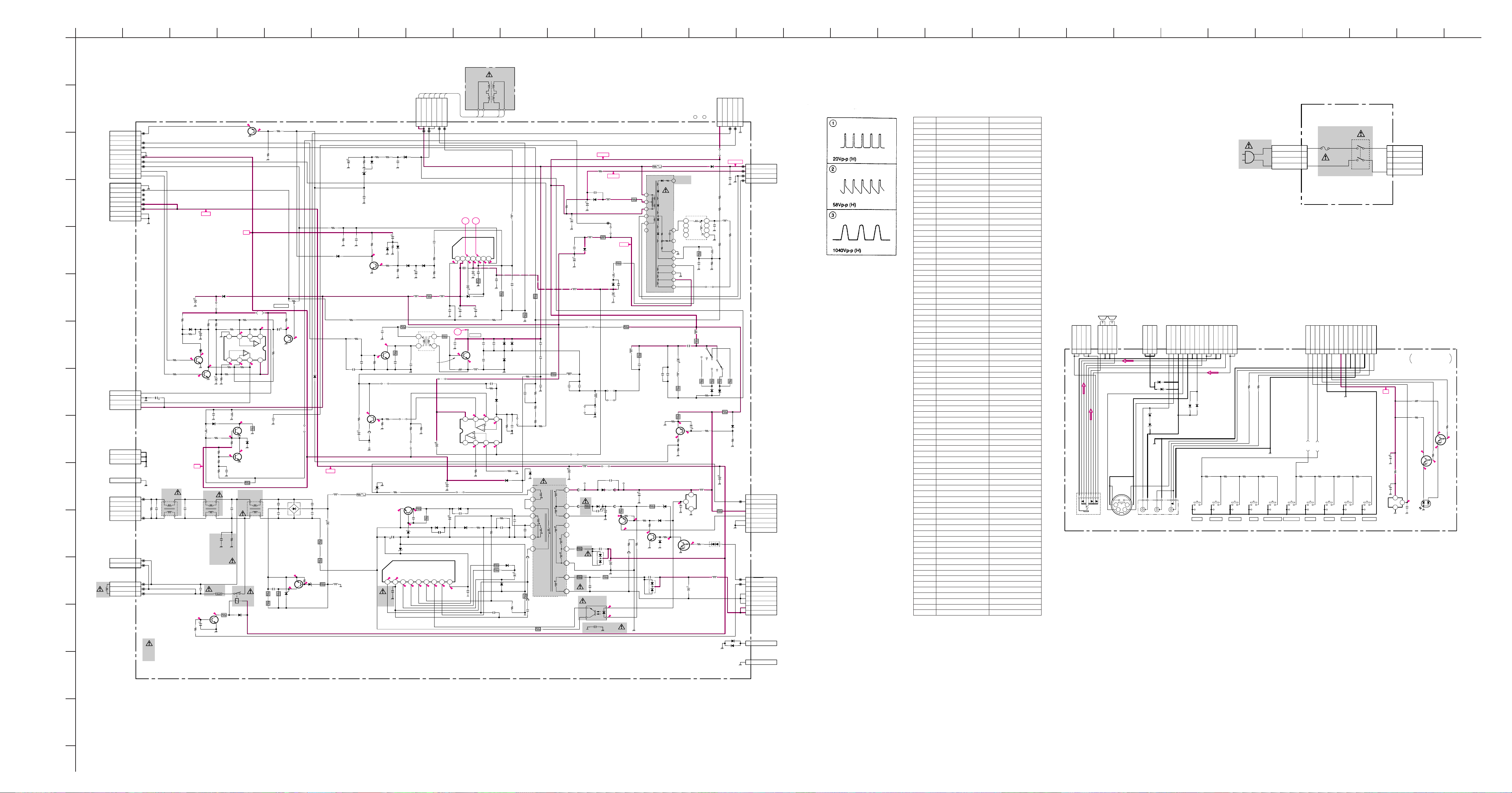
D
POWER SUPPLY, DEFLECTION
– D Board –
D BOARD
IC
IC601 C–5
IC602 E–3
IC603 E–5
IC1501 D–8
IC1800 G–7
IC2504 F–5
TRANSISTOR
Q600 D–5
Q601 E–3
Q602 E–2
Q603 G–1
Q803 F–3
Q1501 F–7
Q1502 H–4
Q1800 G–6
Q1802 H–5
Q1803 H–6
Q1804 G–2
Q1805 G–2
Q2502 F–10
Q2503 F–6
Q2591 D–10
Q2600 B–1
Q2601 B–6
DIODE
D601 D–5
D602 D–4
D603 D–5
D604 D–1
D605 G–10
D606 D–4
D608 D–2
D609 E–2
D611 E–1
D612 E–2
D614 E–3
D616 D–5
D617 C–5
D618 G–1
D619 G–10
D621 C–5
D633 E–2
D801 D–8
D803 F–4
D814 B–7
D815 C–8
D816 C–7
D824 G–8
D825 F–6
D1501 F–7
D1502 F–6
D1503 E–8
D1504 E–8
D1505 G–4
D1506 F–8
D1509 F–8
D1510 F–8
D1511 F–8
D1803 H–6
D1804 H–6
D1805 G–3
D1806 G–2
D1808 H–7
D2500 G–4
D2501 F–5
D2502 F–4
D2506 D–9
D2507 D–10
D2508 E–10
D2510 G–7
D2511 F–8
D2515 G–5
D2600 A–6
D2602 B-1
D2603 A–6
D2604 B–6
VARIABLE
RESISTOR
RV1801 G–5
F1
AC IN
– F1 Board –
– H3 Board –
H3
CONTROL SW, INPUT TERMINAL
– 35 –
– 36 –
– 37 –
– 38 –
0
0
5.2
5.2
0
0
5.1
5V
AUDIO(R)
AUDIO(L)
AUDIO(R)
AUDIO(L)
123
4
123
4
V
L
R
-2
-2
G
R
123
3
1
2
123456789
1011121314
15
123456789
1011121314
15
12
34
J901
D904
C901
R918
S902 S904
S906 S908
S910 S909 S907 S905 S903 S901
J903
J902
IC900
CN902
CN908
CN907
CN905CN901
D915
D914
Q900
Q901
D916
D917
D902
D905
R900 R901
R902 R904 R906 R908 R903 R905 R907 R909
C902
R912
C900
R917
R914
R915
SPB-26MVWF
2 COLOR LED
470p
100
SBX1981-11
4P
WHT
S-MICRO
4P
S-MICRO
3P
BLACK
:S-MICRO
15P
BRIDGE
15P
BRIDGE
1SS119
LIMITTER
1SS119
LIMITTER
DTC144ES
LED DRIVE
DTC144ES
LED DRIVE
1SS119
LIMITTER
1SS119
LIMITTER
JW(5MM)
75
4.7k 4.7k
470 1k 1.8k 3.3k 470 1k 1.8k 3.3k
47
16V
47
47
16V
100
330
330
KEY 1
KEY 2
SP L
SP L
SP R
SP R
PH R
SP R
SP L
PH L
W IN
W IN
W OUT
W OUT
FR L OUT
GND
FR R OUT
GND
GND
RED
GREEN
GND
FR Y OUT
FR C OUT
GND
FR V OUT
GND
SIRCS
STBY+5V
GND
S3
KEY 2
KEY 1
GND
SP GND
SP GND
SP GND
SP GND
SP GND
SP GND
7V
GND
GND
BRIDGEBRIDGE
SP(L)SP(R)
TO A BOARD CN103
H3
CONTROL SW,
INPUT TERMINAL
TV/VIDEO VOL - VOL + PROGR - PROGR +MENU +ENTER MENU - MENU AUTO PROG
TO A BOARD CN102
TO D BOARD 2601
SIRCS
RECEIVER
STANDBY/STEREO/
WAKEUP INDICATOR
B-SS6667<ME.>-H3.
1
2
3
4
1
2
3
4
5
S1690
F1690
CN1691CN1690
5P
:VH-L
4P
:VH-L
34
12
AC OUT
NC
NC
NC
AC OUT
NC
NC
AC
AC
F1
TO D BOARD
CN2600
(AC IN)
B-SS6534<EM.>-F1.
(1) Schematic Diagrams of D, F1 and H3 Boards
1 2 3 4 5 6 7 8 9 101112131415161718 2019 21 22 23 24 25 29282726 30
A
B
C
D
CN506
10P
BLK
:BRIDGE(R)
TO A BOARD
CN109
X-RAY
VTIM
H DRIVE
ABL
GND
9V
E/W
V+OUT
ROTETION
N/S-MUTE
GND
V-OUT
N.C
N.C
11V
11V
GND
GND
CN526
8P
BLK
:BRIDGE(R)
TO A BOARD
CN108
1
2
3
4
5
6
7
8
9
10
1
2
3
4
5
6
7
8
11V
E
F
G
H
I
J
K
L
M
N
O
P
CN1804
*
BLK
:S-MICRO
TO VM BOARD
CN962
N/S COIL+
GND
N/S COIL-
15V
CN2601
3P
WHT
TO H3 BOARD
CN907
GND
GND
GND
CN525
1P
A GND
AC IN
NC
NC
NC
AC IN
CN2600
5P WHT :VH
TO F1 BOARD
CN1691
CN2602
2P
WHT
:MINI
DGC CHK
DGC CHK
OPEN
DGC
NC
DGC
CN2605
3P
WHT
:MINI
TO DGC
R1806
*
R1805
*
R1807
*
4
3
2
1
1
2
3
1
R2612
1/2W
1
2
3
4
5
1
2
1
2
3
1M
TH
C2620
0.22
250V
C1812
*
T2603
8.2MH
21
34
D
(POWER SUPPLY,DEFLECTION)
C1809
*
D1803
*
STOPPER
C1804
*
R1808
*
D1804
*
0.4
Q1802
*
PVM-AMP
0.3
(0)<0>
Q1803
*
N/S-MUTE
D1805
*
L1805
*
9V
C2602
0.22
250V
C2618
0.01
630V
:PP
Q2600
2SC2785TP-HFE
0
C2605
R2602
1k
R1821
0.9
C1813
T2601
11.5
47
– 39 –
0.7
Q1502
2SA1175TP-HFE
9V
D1808
*
STOPPER
JW028
*
R1825
*
R1822 R1823
IC1800
* N/S-DRV
**
*
R1824
4.8
GND
5 6 7 8
(0.3)<5.0>
*
R1814
R1817
R1816
R1815 C1806
C622
470p
250V
4.8
4.8
R1811
R1812
*
*
R1810
*
R1809
*
C1805 L1806
**
Q1805
0.4
R1818
*
*
*
**
C2604
B
THP260
R2603
JW(5MM)
14.8
*
*
-0.8
0.22
250V
R2601
8.2M
D2602
1SS119-25TD
D1806
0.4
Q1804
*
21
34
1W
RY2600
T2602
8.2MH
R1523
0
100
R1524
22k
RV1801
H.POST
9V
R1800
4.8
*
C1800
*
1234
R1801
9V
4.5
C1807
R1820
*
*
R1819
*
C2607
0.0047
500V
E
C2606
0.0047
500V
D2603
5P4M
POWER-SW
C2613
0.68
B
R2604
3.3
10W
:RB
R2607
3.3
10W
:RB
R2605
820
:FPRD
*
*
3.8
3.2
Q1800
*
BUFFER
*
*
JW1802
D2600
D4SB60L
AC-RECT
E
-0.4
-0.1
2
3
2SC2785TP-HFE
1
1SS119-25TD
D1505
*
C2610
0.0047
500V
E
R2611
8.2k
3W
:RS
R2610
8.2k
3W
:RS
R2608
47k
-1.6
D2604
RD8.2ESB2
Q2601
PC-SW
1SS119-25TD
11V
C2609
0.0047
500V
E
R2606
820
:FPRD
C877
0.47
D1502
RD33ES-T1B
PROTECT
R1501
10k
R1502
6.8k
D1501
R1508
10k
C2553
R2529
JW(5MM)
C2552
22
L601
0.45µH
C2617
560
400V
L600
0.45µH
R895
R898 R894
18k
1SS119-25TD
C1518
0.1
:PT
C1501
330p
D1509
1SS119
R1504
4.7k
0.2
0.7
Q1501
2SC2785TP-HFE
V-PROTECT
R2521
C2522
330
*
74.7
Q2502
2SC2688-LK
H-DRIVE
C2547
-0.1
330p
R2520
B
*
Q2503
17.0
2SD2394
2
PIN-OUT
1
0.5
3
R2510
FB2502
JW(5MM)
JW2522
5MM
MTZJ-T-77-5.6B
R611
0.1
1/2W
:RF
C2603
DY1
6P
H+H+H-H-V-
WHT
:DY
12345
D824
560k470k
RGP02-17
R1506
R1503
15k
R2517
R2556
2.7k
33k
1.2k
3W
:RS
C1511
100
16V
R1525
100k
R2519
C2524
820p
500V
JW2505
C875
1000p
500V
E
D1510
1SS119
D1511
1SS119
*
B
5MM
C1510
0.1
:PT
D1506
1SS119-25TD
C1521
47
L1503
R1520 JW067
10µH
0.39
2W
:RS
1
T2502
HDT
3 4
Q2591
2SC4927-01
H-OUT
C2523
*
JW2510
7.5MM
R2505R2508
**
JW2512 C2543
5MM 220
IC1501
TDA8172
V.OUT
R1550
10k
R1551
2.2k
7.5MM
C1503
5
PIN-CONTROL
D825
(0)
3.3k
JW2517
5MM
2.2k
D2500
2W
R601
10k
3W
:RS
81.6
D601
1.5
C2504
100
25V
D602
D1NL20-TA
C624
680p
500V
0.20.1
R2582 JW2502
470 7.5MM
R616
Q600
100
2SD1640Q
:RS
CLAMP
8.6
C633
1000p
500V
8.5
470
16V
0.1273
RD7.5ES-T1B1
D621
RD13ES-T1B
IC601
STR-S6708N
0.9
-0.1
C618
1 2 3 4 5 6 7 8 9
470p
250V
B
V+
6
1.5
C1509
2.2
:BP
C1505
220
330p
IC2504
µPC4558C
35V
C602
10
100V
B
DY
H.DY H.DY V.DY V.DY
12
Vcc
F.B.-PLS
Vee
DRV-IN
1 2 3 4 5 6 7
3
0
R2516
47
D606
RGP10G
8.61.6
C626
1000p
OUT-PUT
-15.6
-14.2
C1579
470 25V
R1515
1.5
:FPRD
D1503
GP08DPKG23 V.BOOST
C1504
C1515
470
0.1
25V
:MPS
TP84
H.OUT
C2519
*
0
L2506
0.68µH
0.2 3.7
1 2 3 4
6.3 1.7 0
R2531
JW(5MM)
C620
680p
500V
B
D616
D1NL20-TA
R612
1.8k
B
Vcc(OUT)
REF-VOLT
1.5
14.5
C1506
0.33
0.3
:MPS
C1514
0.1
:MPS
R1509
6.8k
:RN
ERC06-15S
C2548C2520R2515
***
C2521
0.047
400V
:PP
R2580
*
5678
1.6
1SS119-25TD
R620
4.7k
R604
10
3W
:RS
R621
JW(5MM)
C629
680p 2kV B
R1511
220
3W
:RS
D2506
DAMPER
ERD29-08J
PIN-DANPER
C2510
*
D2515
JW(5MM)
CLAMP
R2564
*
R2526
JW(5MM)
D2501
R614
1.2k
C604
1000p
:B
D617
JW(10MM)
D603
D1NL20-TA
R619
100
L1502
10µH
:LHL08
C1507
0.1
100V
R876
:MPS
2.2k
:FPRD
R1512
1
2W
:RS
D2507
ERC06-15S
DAMPER
D2508
R2536
C2501
*
R2548
JW(5MM)
R2547
JW2515
5MM
C2540
0.022
:PT
C642
820p
500V
B
D2
C643
1000p
500V
B
FB601
1.1UH
C603
330
16V
R618
0.18
2W
:WW
C2518
*
C2515
0.0047
R2512
*
*
D2502
1SS119-25TD
6
P1
7
8
2
3
D1
4
P2
9
FB602
1.1UH
C605
1000p
3kV
R602
1k
:FPRD
680p
2kV
B
C2517
*
R2501
2.2
:FPRD
200V
:PT
R2543
*
T601
SRT
C684
2200
16V
S1
S5
S3
S4
S2
CN518
5P
TO VM BOARD
CN961 4 - 8 PIN
135V
NC
QP-
QP+
GND
12345
D BOARD WA VEFORMS
D BOARD MARK LIST
C818 # 0.047 630V : PP
C1800 # 10 50V
C1804 # 10 50V
C1805 # 0.047 200V : PP
C1806 # 0.015 50V : MPS
C1807 # 0.68 50V : MPS
C1809 # 1000 25V
C1812 # 22 50V
C1813 # 10 50V
C2501 0.22 50V : PT #
C2505 # 0.1 200V : PP
C2510 0.0027 50V : PT 0.0022 50V : PT
C2517 330p 2kV B 680p 2kV B
C2519 0.017 2kV : PP 16000p 2kV : PP
C2520 680p 2kV B 330p 2kV B
C2522 0.01 200V : PT 0.047 200V : PT
C2523 680p 50V B #
C2528 1.8 200V : PP 1.2 200V : PP
C2530 0.91 200V : PP 0.82 200V : PP
C2546 # 0.047 400V
C2548 560p 2kV B #
C2553 # 220p 50V B
CN1804 # 4P BLK : S-MICRO
D1803 # 1SS119-25TD
D1804 # 1SS119-25TD
D1805 # RGP10GPKG23
D1806 # 1SS119-25TD
D1808 # GP08DPKG23
IC1800 # M5216P
JW018 # 10.0MM
JW028 # 7.5MM
JW029 # 10.0MM
C846
33
160V
:HR
R836
68k
L1501
10µH
:LHL08
C839
47
250V
C836
470p
500V
B
C835
470
25V
L815
10µH
:LHL08
135V
R856
JW(5)
200V
C816
220p
500V
B
L812
D815
RGP10GPKG23
200V.RECT
R853
0.47
1/2W
JW018
:FPRD
D814
RGP10GPKG23
+15V.RECT
D816
RGP10GPKG23
-15V.RECT
*
15V
R854
0.47
1/2W
:FPRD
L816
10µH
:LHL08
C840
470
25V
:FPRD10µH
C841
470p
500V
B
R885
0.47
1/2W
+B
H2
H1
C
200V
R804
1
4
2
5
6
3
1k 1W :RF
NX-4002
HV
13
FV
12
11
ABL
7
-15V
8
E
9
15V
10
T801
FBT
8
7
6
5
R855
1k
1/2W
:RS
D801
RGP02-20EL
1000V.RECT
T804
*
4
3
2
1
L802
*
C842
0.068
200V
:PT
JW029
JW036
12.5MM
0.0047
R871
20k
:RN
R869
*
C818
*
L801
*
R810
*
R868
*
R858
4.7k
:RN
*
1000V
C808
2kV
E
CN0521
:MINI
TO C2 BOARD
1
1000V
2
200V
3
GND
4
H1
4P
CN701
JW064 # 7.5MM
JW083 # 10.0MM
JW1802 # 5.0MM
L801 # : CD1
L802 47k 1/4W 2.2mmH : EL0606
L1805 # 10mmH
L1806 # 3.3mmH
Q1800 # 2SA1175TP-HFE
Q1802 # 2SC2785TP-HFE
Q1803 # 2SC2785TP-HFE
Q1804 # 2SC2785TP-HFE
Q1805 # 2SC2958-TL
R810 # 33 1/4W
R868 18k 1/4W : RN 22k 1/4W : RN
R869 20k 1/4W : RN 22k 1/4W : RN
R1800 # 1k 1/4W
R1801 # 5.6k 1/4W
R1805 # 10k 1/4W
R1806 # 4.7k 1/4W
R1807 # 10k 1/4W
R1808 # 4.7k 1/4W
R1809 # 33k 1/4W
R1810 # 33k 1/4W
R1811 # 33k 1/4W
R1812 # 33k 1/4W
R1814 # 10k 1/2W
R1815 # 10k 1/2W
R1816 # 3.3k 1/4W
R1817 # 100k 1/4W
R1818 # 2.2k 1/4W
R1819 # 100 2W : FPRD
R1820 # 1.8k 1W : RS
R1821 # 33k 1/4W
R1822 # 33k 1/4W
R1823 # 5.6k 1/4W
R1824 # 33k 1/4W
R1825 # 3.3k 1/4W
R2503 JW (15.0MM) 68 3W : RS
R2505 560 1/4W 1.5k 1/4W
R2506 JW (20.0MM) 56 3W : RS
R2508 2.2k 1/4W 1.8k 1/4W
R2512 56k 1/4W 220k 1/4W
R2515 0.22 1W : RS 0.39 1W : RS
R2519 5.6k 1/4W : FPRD 4.7k 1/4W : FPRD
R2522 # 180 2W : RS
R2523 # 220 2W : RS
R2532 68 3W : RS JW (15.0MM)
R2536 3.9k 1/4W 2.7k 1/4W
R2543 3.9k 1/4W 4.7k 1/4W
R2547 180k 1/4W 0.047 50V : PT
R2564 2.7k 1/4W #
R2580 56k 1/4W 82k 1/4W
RV1801 # 47k
S2501 # 1-572-707-21
T804 # 1-413-059-11 (DFT)
L2510
3.3mmH
14
56V
13
12
16
18
17
15
30V
11
10
JW2514
7.5MM
FB604
1.1UH
+B
FB605
1.1UH
GND
7V
14V
11V
R625
GND
R624
JW877
15MM
C2530C2546
**
L2504
PmC
JW2518JW2506
7.5MM7.5MM
L607
150µH
:LHL13
RGP15G
R615
0.47
:FPRD
7A
D604
D5LC20U
ON3171-R
3
4
PHOTO COUPLER
JW624
7.5MM
C610
1000p 3kV
RU4AM-T3
C621
680p
D608
500V
B
2SA1315-Y
C612
680p
500V
B
C644 R629
820p
0.56
500V
5W
B
:RS
IC603
2
1
JW2507
5MM
JW2508
5MM
D609
FB603
1.1UH
C609
4.7
100V
Q601
C2601
470p
250V
FB600
1.1UH
69.2
70.2
B
L2509
HLC
R606
75.3
R628
4.7
1/2W
FB607
1.1UH
C614
2200
25V
R2518
1.5k
3W
:RS
TP602
18
1W
:RS
R690
820
10.5
R2528
680
1/2W
:FPRD
C2529
0.001
100V
:PT
2SA1091R-TPE2
C613
560
160V
RD7.5ESB1
R608
22k
1/2W
:FPRD
75.3
1SS119
R607
R634
3.3k
100
75.2
R609
5.6k
1/2W
Q602
2SC3209-L
C611
680p
500V
B
R887
1.8k
:FPRD
R884
200k
1/2W
:RN
Q803
D612
D614
R635
470
0
D633
1SS119
PROTECT
D611
D5LC20U
**
0
R861
56k
C632
0.047
100V
C2526
0.15
200V
:PT
C2527
10
160V
L2508C2528C2505
1.5mmH
NSL0808
R2527
47
1W
:RS
137.2
R860
56k
IC602
SE135N
:PT
2
69.1
Q603
DTD114ES
L2505
10mH
:DCC
R2533
4.7
:FPRD
S2501
*
R2503R2523
**
R2532
*
D2511
GP08DPKG23
H-POSI
C814
100
16V
R892
137.0
4.7k
L606
1
15µH
:LHL08
R603
33k
2W
3
:RS
3.5
R622
100
C615
2200
S2502
SW
R2522
*
R2506
*
D2510
GP08DPKG23
H-POSI
R886
1.2
2W
:RS
D803
R890
150k
1/2W
C683
2200
16V
D618
1K
L605
15µH
:LHL08
D605
1SS119
D619
1SS119
B-SS6667<ME.>-D..
1SS119-25TD
1
H RELAY
2
AFC
3
14V
4
33V
5
BACKUP
6
GND
7
GND
8
7V
CN520
8P
BLK
:BRIDGE(R)
TO A BOARD CN107
CN528
8P
BLK
:BRIDGE(R)
TO A BOARD CN106
1
STBY
2
DEGUSS
3
NC
4
AUDIO GND
5
AUDIO GND
6
AUDIO GND
7
AUDIO 30V
8
AUDIO 30V
CN530
1P
TO A BOARD CN127
1
GND
CN527
1P
1
GND
– 40 – – 41 –
*
KV-J25MF8J KV-J29MF8J
# Mark : not mounted
– 42–

(2) Schematic Diagrams of A Board
V SYNC
SEP
H SYNC
SEP
25
35 34
2423
31
33
32
30
28
37
38
41
40
36
12
43
42
50
48
45444746
5352515961
555657
5463
58
60
62
64
1
26
6
16
39
2927
222120191817151413111097634249
COL
COLOR
& AXIS
BRT
BRT
D.
COL
γ
D. COL γ
PIC
PIC
BLK
LIMIT
VLIN, SCORR
VPOSI, VOFF,
VBIZE
H POSI
AFC
GB CUT
CUT
OFF
GB
DRV
GB DRV
ABL
OSD
MIX
YM/YSZ
SW
YS1
SW
YS1 OFF
Y/C
MIX
VIDEO
SW
AKB
H.DRIVE
ABL
AKB
OFF
EHT
H, V
HV
COMR
PHASE
DET
32f
H
VCO
2f
H
CD MODE
INTERLACE
V FREQ
PHASE
SHIFT
Sand
Castle
KILLER
DET
DEM
AXIS
fsc B-Y
fsc R-Y
PRE/OVER
TOT
WIDE
Parabola
Gen.
1/32GATE
50/60 ID
PHASE
DET
INTER
-LACE
Count Down
525/625
D PIC
DC
TRAN
CLP
SHARP
NESS
SUB
CONT
SUB CONT
EXT
SYNC
TRAP OFF
CV/YC
DL
SHARP
VM
2Vp-p
SHP 10
AGING D PIC
1Vp-p
DC
TRAN
TOTACC
IREF VCO
APC
SUB COLOR
HUE
TRAP
1Vp-p
DL
GATE
WIDE
Saw tooth
Gen.
DEM
XTAI
COLOR SW
HUE
6dB
SYSTEM
INDENT
PAL
ID
ACC
DET
1 2 3 4 5 6 7 8 9 10 11 12 13 14 15 16 17 18 2019 21 22
A
B
C
D
E
55
F
G
H
I
J
K
L
M
N
O
? D F1 F3 boards
Schematic diagrams
TO D BOARD
CN530
FR Y OUT
FR C OUT
FR V OUT
BRIDGE
TO H3 BOARD
CN901
FR L OUT
FR R OUT
STBY+5V
CN103
15P
BRIDGE
TO H3 BOARD
CN905
GND
CN127
1P
SP L
SP L
PH L
GND
GND
SP R
SP R
PH R
GND
GND
GND
GND
CN102
15P
S3
GND
GND
GND
GND
7V
RED
GND
GREEN
KEY 2
SIRCS
KEY1
TU001
BTV-FG441
C078
100
16V
1
B:CHIP
L004
10µH :EL0606
AUDIO(L/R)
1
SPL
2
PHL
3
G
4
G
5
6
SPR
7
PHR
8
G
9
10
G
11
Y
12
13
14
15
10
11
12
13
14
15
SCL
G
C
SDA
V
S3
1
L
2
3
R
4
5
6
7
8
9
7V
C054
0.01
B:CHIP
RED
GRN
KEY2
KEY1
C080
0.01
L080
10µH
:EL0606
GRN
RED
R020
100
:CHIP
R073
10k
:CHIP
VCC5V
VCC30V
SCL
9V
(VC)
(U/V)
C079
C082
0.1 :MPS
220 :CHIP
R071
JR081 JR083
0
:CHIP0:CHIP
BAND 1
C107 R103
100p
:CHIP
1k :CHIP
R008
:CHIP
R031
1k :CHIP
(-0.4)
<-0.3>
SDA
AS
(L/H)
(NC)
C083
0.01
0.01 B:CHIP
B:CHIP
R070
220 :CHIP
D101
BAND 2
1SS119
STOPPER
D102
15K
470
:CHIP
R010
R013
1k
:CHIP
C039
100p
:CHIP
1k :CHIP
C008
100p
R033
1k
:CHIP
C019
0.001
CH:CHIP
5.2
(4.8)
4.9
(5.1)
0
Q030
2SC2712
H DRIVE
MUTE
1.8
(2.5)
[1.3]
<3.2>
C084
0.01
B:CHIP
B:CHIP
B:CHIP
TSW0
TSW1
C012
100p :CHIP
C003
100p CH:CHIP
C005
100p :CHIP
C040
C006
100p
100p
:CHIP
:CHIP
100p :CHIP
220p CH:CHIP
C020
0.001 CH:CHIP
C023
220p CH:CHIP
C066
220p CH:CHIP
C067
220p CH:CHIP
220p CH:CHIP
R041
C014
0.001
CH:CHIP
Q033
DTA144EK
MUTE
R029
4.7k
:CHIP
D002
1SS355
H DRIVE
MUTE
0.2
R019
150k
:CHIP
C004
2.2
RFAGCIF+B
C085
0.01
C091
25V
C089
0.01
R039
C042
C024
C069
100 :CHIP
AFT
GND
SW1
C086
R081
0.01
B:CHIP
1k :CHIP
10µH :EL0606
L082
47
TSW0
R090
10k
:CHIP
S
100 :CHIP
C009
0.001 CH:CHIP
1k :CHIP
R026
SW2
DE-EMOUT
NC
(SIF OUT)
0.01 B:CHIP
C087
TSW1
Q001
2SA1162
R078
10k
:CHIP
R072
10k
:CHIP
R005
100 :CHIP
1.0
R006
100 :CHIP
0(4.5)
R014
1k :CHIP
R009
1k :CHIP
R058
1k :CHIP
C045
0 :CHIP
C065
220p
CH:CHIP
R046
100 :CHIP
R047
100 :CHIP
C068
220p CH:CHIP
R053
100 :CHIP
R061
100
:CHIP
R059
C025
4.7k :CHIP
0.001
CH:CHIP
R036
*
C007
0.47
C034
0.1
25V
B:CHIP
DETOUTNCNC
(MSIFOUT)
120 :CHIP
R1245
R1246
220
:CHIP
C114
100p
22k
:CHIP
:CHIP
C115
10p
:CHIP
R101 R114
4.7k
470
:CHIP
:CHIP
CXP85332A-238S
2
1 2 3 4 5 6 7 8 9 10 11 12 13 14 15 16 17 18 19 20 21 22 23 24 25 26 27 28 29 30 31 32
0
H SYNC
V SYNC
0
PAL/NT
THR
0
TIMER
5.2 [0](0)
RESP/NICAM
0
TSW0
0
TSW1
5.2
AGC
0
NC
0
MUTE
4.2
(4.9)
BLK
4.0
ZOOM
1.9(2.4)
NC
5.4
B-INT
0
DEGAUSS
1.0
V-PULSE
4.2
H RELAY
0
ATT
0
L1/L2
5.2 (0)
C/T
0(5.1)<5.1>
CC ON/OFF
0
S-SYS 1
0
S-SYS 2
0.8
H SYNC
5.1
SIRCS
0.2
HD SW
0.6(0.9)
TV SYNC
5.1
ITT RESET
4.9
ST-BY
0.2
NS MUTE
GND
R028
100 :CHIP
IC002
L78LR05D-MA
5V-REG
12345
C002
22
JW158
17.5MM
R-Y
JR206 R217
0
:CHIP0:CHIP
R115R113
22k
:CHIP
R075
10k
:CHIP
IC001
TUNIG
CONTROLLER
1
(1.8)[1.8]
NS ROT
(7.4)00
<4.9>[4.4]
BAND 2
BAND 1
5.2
[4.7](4.9)
II CLK0
5.2
II CLK1
(4.9)5.2
<4.8>[4.8]
II DAT0
5.2
II DAT1
<5.0>
[5.1]3.0
<5.1>
[5.1]3.0
<5.1>
5.2
X-RAY
2.4
<1.7>[2.0]
5.2
5.2
5.2
<0.8>
RESET
5.2
EXTAL
2.2
2.6
BINTRDY
2.2
<1.8>(2.5)
5.26.1
C052
0.1
25V
B:CHIP
Q306
2SC2712
0
B-Y
:CHIP
VC RIPPLE FILTER
100
:CHIP
16V
R074
18k
:CHIP
R054
10k :CHIP
L001
:EL0606
VDD
NC
0
GND
0
MP
C013
100p :CHIP
NC
*
R015
*
YM
0
YS
C027
0
I
0
B
0
G
0
R
0
EXLC
220p CH:CHIP
XLC
N/F
KEY2
KEY1
AFT1
*
AFT2
*
VC
M/S
0
XTAL
3334353637383940414243444546474849505152535455565758596061626364
C044
100p :CHIP
R007
10k :CHIP
L002
10µH
:EL0606
C053
B:CHIP
R030
100k
:CHIP
R345
1k
:CHIP
JR012JR013
0
:CHIP
TV
Q109
2SC2712
R116
22k
:CHIP
C120
0.068
:PT
R119C122
1.8k
1µH
0.0015
B:CHIP
C033
2.2
16V
F:CHIP
C001
0.0015 B:CHIP
100p :CHIP
1k :CHIP
R016
1k :CHIP
100p :CHIP
100p :CHIP
100p :CHIP
100p :CHIP
100p CH:CHIP
100p CH:CHIP
220p CH:CHIP
R038
R042
R040
C029
R069
R064
100
:CHIP
C017
100p
:CHIP
R057
1k
:CHIP
R118
:CHIP
R117
22k
HZT33-02
:CHIP
33V-REG
C116
0.1
:MPS
C121
0.068
R120
:PT
330k
:CHIP
Q110
2SC2712
VC RIPPLE FILTER
R004
4.7k
:CHIP
C056
C011
BAND 2
BAND 1
C051
C050
C049
C048
C026
R063
100 :CHIP
C028
1.2k :CHIP
1.2k :CHIP
1.2k :CHIP
220 :CHIP
R018
1k :CHIP
R065
R035
4.7k
4.7k
:CHIP
:CHIP
C064
0.022
56p CH
B:CHIP
R048
100 :CHIP
KEY1
KEY2
CAS/4HG
3
C010
0.022
B:CHIP
C022
100
Q031
2SA1162
0.1
25V
SYNC SEP
1.5
R043
22k
C031
:CHIP
47p
CH:CHIP
R361
0 :CHIP
R347
1k
:CHIP
Schematic diagram
A board /
22k
IC102
C117
100p
:CHIP
R003
R002R001
4.7k
4.7k
4.7k
:CHIP
:CHIP
:CHIP
0.001 CH:CHIP
C021
L003
15µH :EL0606
C325
1.8K
:CHIP
C015
C030
0.022 B:CHIP
C037
220p CH:CHIP
C032
220p CH:CHIP
X101
5V
D005
GP08D
C038
100
8.8
R044
10k
:CHIP
C119
0.01
F:CHIP
R032
*
R062
100 :CHIP
C035
0.001
B:CHIP
C018
18p
:CHIP
RD4.7ES-T1B
C016
56p
:CHIP
CH
R055
82k
:CHIP
C041
0.1
25V
B:CHIP
R049
1M
:CHIP
C108
C109
1000
0.0047
B:CHIP
25V
C118
22
C055
470
16V
C074
R077
220p
100
B:CHIP
:CHIP
5.2
CLK
IC003
AT24C04A
-10PC-B
5V MEMORY
1 2 3 4
D001
C327C326
1.8K
1.8K
:CHIP
:CHIP
R066
4.7k
R056
100
:CHIP
C043
100p
CH:CHIP
220
:CHIP
5.2
5678
DAT
YM
YS
B
G
R
R050
2.2k
:CHIP
B-Y
GND
B INT
123
R076
100
:CHIP
C057
220p
CH:CHIP
YS
5V
R-Y
B DAT
B CLK
4
R182R181
220
:CHIP
220 :CHIP
1SS355
R180
RGB MUTE
SCL
SDA
C072
470
16V
C046
100p
:CHIP
33V
CN118
4P
D105
R153
0 :CHIP
R192
100k
:CHIP
DTC144EK
RGB MUTE
:S-MICRO
R155
:CHIP 0
Q108
CN120
RED
R156
180
:CHIP
0
R157
:CHIP
R154
180 :CHIP
D104
DAN202K
R OUT
RGB MUTE
R171
22k
:CHIP
D111
RD11ES-T1B2
4.4
(9.6)
[9.4]
<8.4>
0
(-0.3)
<-0.3>
R160
10k
:CHIP
9V
123
GND
3P
VM OUT
TO VM BOARD
CN961 1 - 3 PIN
G OUT
R OUT
6
G OUT
B OUT
9V
Y
C
R1219
S
R1220
C1214
0.001
:CHIP
9V
B OUT
GND
9V
180 :CHIP
R158
C1204
C1201
0.01 F:CHIP
R1205
R1213
10k :CHIP
C1246
V
R1215
L
R1216
R1217
R
R1218
100 :CHIP
100 :CHIP
SCL
R1222
100 :CHIP
SDA
R1224
100 :CHIP
R1235
0
:CHIP
C1215
R1234
220k :CHIP
CN117
:S-MICRO
TO C2 BOARD
IK
CN703
12345
IK
R/G/B
C420
47
25V
100
R1277
16V
:CHIP
R1278
:CHIP
10k :CHIP
47 25V
100 :CHIP
100 :CHIP
100 :CHIP
100 :CHIP
R1221
10k :CHIP
R
D1201
UZ-9.1BS-TA PROTECT
C1217
1
16V
F:CHIP
C1216
1 16V F:CHIP
0.001
:CHIP
0 :CHIP
R
JR032
6P
D1220
UZ9.1BS
V
4.2
L
4.2
4.2
100
R
4.2
4.2
100
8.3
4.2
4.2
8.3
4.2
4.2
4.2
4.2
4.2
8.3
4.8
4.9
4.2
L
0 :CHIP
R1236
D1202
UZ-9.1BS-TA PROTECT
C1218
47 25V
R1237
220k
:CHIP
JR031
0
:CHIP
L
V
4.2
L
R
V
0 :CHIP
R1247
V
0:CHIp
D1203
C1219
C1257
470p
CH:CHIP
C1242
0
:CHIP
R1288R1289
LRL
IC1201
4
5
6
7
8
:CHIP
R
C OUT1
Y OUT1
BIAS
TRAP 1
V OUT1
L OUT1
4.2
R OUT1C2
4.2
Y IN1
C IN1
MUTE
TRAP 2
V CUT2
L OUT2ADR
Y OUT2
R OUT2
C OUT2
0
LTV
TV
RTV
VCC
GND
EV
REV
LEV
4.2
68k :CHIP
4.2
25 26 27 28 29 30 31 32 33 34 35 36 37 38 39 40 41 42 43 44 45 46 47 48
0
:CHIP
C1243
CXA1855S AV SELECT
123456789101112131415161718192021222324
V1
LV1
Y1
RV1
C1
S1
V2
LV2
Y2
RV2
S2
V3
LV3
Y3
RV3
C3
S3
SCL
SDA
R OUT3
V OUT3
L OUT3
12V
Y
C
S
D1205
D1204
PROTECT
PROTECT
PROTECT
UZ-9.1BS-TA
UZ-9.1BS-TA
C1220
47 25V
0.01 F:CHIP
R1240
R1239
75
:CHIP
:CHIP
Y
C
C265
UZ-9.1BS-TA
F:CHIP
Q1206
2SC2712
S1 DETECT
R1241
100k
:CHIP
R1242
2.2k :CHIP
75
0
(-0.6)
S3
[-0.1]
<-0.5>
R-Y/B-Y
R801
100
:CHIP
R1254
470k
:CHIP
C1226
1
16V
F:CHIP
D1208
R1255
1k :CHIP
UZ-9.1BS-TA PROTECT
R
4.2
4.2
TV
4.2
4.2
C
Y
R1211
C1207
33
4.2
4.2
V
L
R1276
100 :CHIP
R
R1275
100 :CHIP
G
4.2
4.2
C1210
4.2
4.2
4.2
4.2
4.2
4.2
AUDIO(L/R)
L
C268
100
16V
R
G
1
16V
C267
0.047
25V
B:CHIP
8.3
C264
0.0047
B:CHIP
R1243
100k
:CHIP
MONITOR
AUDIO
R
R4
470
:CHIP
R1256
470k :CHIP
R1258
470k :CHIP
C1227
1
16V
F:CHIP
1k
R1257
D1209
PROTECT
L
UZ-9.1BS-TA
AUDIO(L/R)
C1205
R1206
0.47
5.6k
25V
:CHIP
F:CHIP
R1202
100 :CHIP
R1207
5.6k :CHIP
4.1
R1201
100 :CHIP
Q1201
2SC2712
Q1202
BUFFER
2SC2712
BUFFER
R1208
R1204
100
:CHIP
:CHIP
R1203
:CHIP
R1212
100
:CHIP
Y
C1208
25V
C
R1223
470
:CHIP
47
25V
R1228
100 :CHIP
R1226
100
:CHIP
R1227
100
:CHIP
C266
1
16V
F:CHIP
12345678910
IN L NC
VCAP
IN R
VCC
AGND
BAS R
6.1
BAS R
6.1
TRE R
6.1
OUT R
6.1
DGND
R268
100
:CHIP
R
– 44 –– 43 –
L/MONO
OUT
L4
R1298R1299
470
:CHIP
C1256
470p
CH:CHIP
470 16V
C1228
D1210
PROTECT
:CHIP
UZ-9.1BS-TA
V
V
C1203
47
25V
3.5
4.1
180
220
Q1203
2SC2712
BUFFER
R1210
180
:CHIP
47
C1209
47
25V
L1201
18µH
:EL0606
C1213
100p
Q1204
:CHIP
2SA1162
BUFFER
R1225
100
:CHIP
6.1
12.1
PS.1
6.1
NC
PS.2
BAS L
BAS L
TRE L
OUT L
S CLK
S DAT
IC206
TDA8424
AUDIO
PROCESSOR
VIDEO
R
V4
R1259
68
:CHIP
JR006
0
:CHIP
C1206
0.47
25V
F:CHIP
3.5
4.1
R1209
220
:CHIP
R1214
470
:CHIP
R1232
220
:CHIP
R1231
0
:CHIP
4.2
4.1
Q1205
2SC2712
BUFFER
6.1
6.1
6.1
6.1
11 12 13 14 15 16 17 18 19 20
4.8
AUDIO(L/R)
R-Y/B-Y
AUDIO
R3
V
L
R
3.2
R1233
1.5k
:CHIP
4.8
R269
100
:CHIP
3.5
4.8
B:CHIP
0.0047
B:CHIP
L/MONO
L3
V
C270
0.047
25V
C269
SCL
SDA
R270
100
:CHIP
L
R
VIDEO IN 3
V3
C1253
470p
CH:CHIP
R1262
220k
:CHIP
R1260
220k
:CHIP
F:CHIP
:CHIP
D1211
PROTECT
R
UZ-9.1BS-TA
V
R271
100 :CHIP
JW164
7.5MM
J1202
9P
L/MONO
AUDIO
L2
R2
C1252
470p
CH:CHIP
R1264
75 :CHIP
C1229
C1230
1
1
16V
16V
F:CHIP
4.7k
4.7k
:CHIP
D1213
D1212
PROTECT
UZ-9.1BS-TA
L
UZ-9.1BS-TA PROTECT
Y
C
VIDEO IN 2
R1
V2
C1251
470p
CH:CHIP
R1267
R1265
220k :CHIP
C1231 C1234
C1232
47
25V
16V
F:CHIP
R1266 R1268R1261 R1263
4.7k
:CHIP
220k :CHIP
1
L1
R1269
75 :CHIP
C1233
1
16V
F:CHIP
4.7k
:CHIP
VIDEO IN 1
V1
C1250
470p
CH:CHIP
47
25V
L/MONO
AUDIO
R
D1214
RD9.1ES PROTECT
V
D1215
UZ9.1BS-TA PROTECT
LVR
D1216
UZ-9.1BS-TA PROTECT
N/S MUTE
R/G/B
DL300
DL
C
Y
C136
0.47
25V
B:CHIP
4.3
IC104
CXA2050S
Y/C
JUNGLE
L108
10µH
9V
:EL0606
C134
C133
0.01
47
B:CHIP
25V
0.47
Q352
2SC2712
BUFFER
Q320
2SC2712
BUFFER
R178
2.9
C093
47
25V
100
:CHIP
:CHIP
R176
3.3k
2.2
R177
1k
:CHIP
9V
5.7
R363
:CHIP
C363
JW(5)
0
CN121
12P
:BTOB
TO S1 BOARD TO S1 BOARD
CN2201
9V
SDAT
SCLK
GND
12V
L IN
R IN
GND
L OUT
R OUT
101112
G
L
R
AUDIO(L/R)
AUDIO(L/R)
8.3
123456789
SDA
9V
IC201
PQ09RF2
9V REG
9V
IO
G
C211C212
0.47
100
16V
16V
B:CHIP
R208
IC205
120
L7812CV
3W
:RS
12V REG
IO
G
C214
0.1 :PT
SCLRL
R253
0.56
3W
:RS
C210
0.47
16V
B:CHIP
JR205
0
:CHIP
C213
10
GND
AUDIO(L/R)
ROTATION
D220
RD5.6ESB
R215
47k
:CHIP
R142
L110
1k
10µH
:CHIP
:EL0606
C129
220 :CHIP
0.01 B:CHIP
R111
C147
HSIN
3.4
4.3
12
5.2
SCP OUT
0.9
4.0
1
C130
470 :CHIP
R149
C149 R112
1 16V F:CHIP 100 :CHIP
VSIN
VSFIL
2.4
YRET
(R-Y)IN
1 16V F:CHIP
C148
R-Y
220k :CHIP
R148
0.47
:MPS
X104
503K
C152
47
25V
R267
470
:CHIP
R121
10k
:RN-CP
0.01 B:CHIP
C156
0.0047
B:CHIP
C151
IREF
D GND
1.9
2.6
D VCC2
CXA2050S
13
0
S GND2
YS1
(B-Y)IN
5.7 5.6
R151
560 :CHIP
0.01 B:CHIP
C153
R122
1 16V F:CHIP
220 :CHIP
C150
B-Y
:CHIP
R124
Q106
2SA1162
*
C146
100p
CH:CHIP
R141
R145
4.14.2
CVIN
DCTRAN
[8.6]
5.6
NC(DATEST)
X358
R144
1.5k
:CHIP
X102
C141
18p
CH:CHIP
SDA
10
C145
4.8
3.6
BLHOLD
VIDEO OUT
<0.1>
1.7(1.5)
FSC OUT
SECAM REF
R107
220
:CHIP
3.3k
:CHIP
SCL
1k :CHIP
1k :CHIP
R106
R108
SCL
SDA
6.4
4.8
109
(3.1)
5.9
S GND1
(R-Y)OUT
(3.1)
R-Y
5.9
Q111
2SC2712
470 :CHIP
BUFFER
R150
JR011
0
:CHIP
1k :CHIP
R110
C170
0.001
VM
4.7
SYNC OUT
11
YOUT
(B-Y)OUT
B-Y
R109
220 :CHIP
Y
R105
100
:CHIP
10
10
C143
10
C140
C142
C1318
0.47
4.1
4.25.1
CIN
YIN
EXT SYNC IN
5.4
2.5(5.0)[*]
7.8(8.2)
X443
S VCC1
APCFIL
1 2 3 4 5 6 7 8 9 10 11 12 13 14 15 16 17 18 19 20 21 22 23 24 25 26 27 28 29 30 31 32
R143
470
:CHIP
15k :CHIP
R104
X103
C137C135
470p
4.43MHz
:CHIP
C139
15p
CH:CHIP
R-Y/B-Y
Y/C
100 :CHIP
R102
R203
10k
R123
4.7k
:CHIP
CERA
4.4
AFCFIL
5.7(5.3)
R1IN
G1IN
0.01 B:CHIP
C155
R125
100 :CHIP
C200
0.01
B:CHIP
5.0
5.7(5.3)
0.01 B:CHIP
C157
100 :CHIP
C101
1
C199
D112
0.1 25V B:CHIP
RD9.1M-T1B
R159
220
:CHIP
DTC114EK
Q105
2.2
C154
C164 C166
C102
0.1
100V
:MPS
0.0022 B:CHIP
0.01 B:CHIP
4700p B:CHIP
C159
C158
L2FIL
3.6
3.0
4.8
D VCC1
HD OUT
AFCPIN/HOFF
(5.4)5.6
5.7(5.3)005.7
B1IN
YS2YMR2IN
220 :CHIP
220 :CHIP
100 :CHIP
R128
1 16V B:CHIP
R132
R126
C163
1 16V B:CHIP
C160
G
R
YM
L109
100µH
:EL0606
R184
2.7k
:CHIP
C162
220
100 :CHIP
16V
R129
470
R130
:CHIP
0.1
100V
:MPS
3.7
4.2
SAWOSC
VAGCSH
VD+OUT
E-W OUT
17
(5.4)
5.7(5.4)
G2IN
B2IN
S VCC2
RSH
47 25V
1 16V B:CHIP
0.01 B:CHIP
C167
C165
C168
D117
B
MA3091-TX
R172
Q113
Q112
DTC114EK
VTIM SW
R135
0
:CHIP
C198
0.001
B:CHIP
100 :CHIP
100 :CHIP
R138
R133
R152
*
22
C189
3.2
3.1
VTIM
ABL FIL
<1.0>[1.0]
(0.9)0.1
VD-OUT/VPROT
[2.1]
[2.1]
1.9
1.9
2.8
R OUT
GSH
G OUT
0.022 :PT
C169
C187 C191
0.022
0.022
:PT
G OUT
R OUT G
100k :CHIP
2SC2712
R174
*
C105
*
R175
*
D107
D352
RD5.1ES
REGULATOR
R186
R303 R170
:CHIP
C375
47
C370
0.1
25V
B:CHIP
5.2
10
12345678
+5V
N.C
GND
I.C.
SYNC
0.9
N.C.
I.C.
I.C.
R-Y IN
N.C.
B-Y IN
18
N.C.
B-Y OUT
R-Y OUT
19
GMD
+5V
TDA4665T
1.6
1.6
9 10 11 12 13 14 15 16
C374
R-Y/B-Y
5.0
R365
100
:CHIP
R364
220
:CHIP
5.0
4.3
Q354
2SC2712
BUFFER
R366
220
:CHIP
R368
220
:CHIP
R304
1k
:CHIP
10
:CHIP
(MAIN TUNER,VIF,SIF,AV SW Y/C DECODE JUNGLE)
7V
33V
W-MUTE
VL IN
VL OUT
12345
L
R
C237
1
C238
1
DTC144EK
AUDIO MUTE
(0.4)
[0.3]
<0.4>
DAN202K
R139
D106
1k
:CHIP
RD6.8M-T1B
0.47
C195
R146
100
:CHIP
C192
2.2
3334353637383940414243444546474849505152535455565758596061626364
IK IN
ABL IN
(2.5)
(9.1)
[3.6]4.0
7.9
1.5
(2.7)
[2.7]
[2.2]
2.9
2.8
2.0
BSH
B OUT
161514
:PT
BGR
IK
B OUT
*
R173
RD8.2M-T1B1
IC351
330
:CHIP
IH DL
C207
0.1
25V
B:CHIP
C206
0.1
25V
B:CHIP
3.4
B-Y
5.2
R-Y
:CHIP
:CHIP
B:CHIP
3.4
47
CN128
:BTOB
GND
C260
0.022
B:CHIP
R245
3.3k
:CHIP
C261
0.022
B:CHIP
R246
3.3k
:CHIP
Q210
CN202
W-MUTE
VR IN
6
0
VR OUT
0
D218
MUTE
Q205
DTC144EK AUDIO MUTE
R164
*
C103
*
0.01 B:CHIP
*
R179
C106
R-Y
R-Y
B-Y
B-Y
R305
100
R306
100
C209
0.1
25V
C219
D353
GP08D
6P
IC203
R258
C250
100
330
:CHIP
16V
C249
R254
330
100
16V
:CHIP
D211
MA111 PROTECTOR
Q209
DTC144EK
AUDIO MUTE
R209
4.5
1k
:CHIP
(0.4)
0
[0.3]
<0.4>
AUDIO(L/R)
C367
47
JW042
25V
12.5MM
C
R392
0
:CHIP
Y
R391
560
:CHIP
1.7
12345678910
47
25V
C224
0.22
25V
B:CHIP
C220
0.1
25V
B:CHIP
C223
0.22
25V
B:CHIP
– 45–
TA8200AH AUDIO OUT
1.6
1
PRE-GND
RIPPLE
3
FILTER
1.6
5
16.7
7
L OUT
9
VCC
PW-GND
4.5
11
R OUT
C217
0.47 25V B:CHIP
D212
MA111 PROTECTOR
Q211
2SA1162
1SS119
C216
330
16V
D210
R211
1k :CHIP
YCM301
(CFB-4)
GNDCVVCC
1 2 4 5 6 73
Q315
2SC2712
BUFFER
S REF
TEST
N.C.
N.C.
+8V
GND
IC354
TDA8395T
SECAM
PROCESSOR
3.4
3.4
11.2
[10.9]
R381
1.2k
:CHIP
S IN
SYNC
N.C.
N.C.
N.C.
N.C.
B-Y OUT
R-Y OUT
11.1
(-9.5)
[-5.1]
<-4.6>
R210
47k :CHIP
COUT
GND
R382
1.2k
:CHIP
11 12 13 14 15 16 17 18 19 20
6.0
(3.1)
-1.1
0.9
6.0
(3.1)
0
2
4
11.9
6
8
5.4
10
16.2
12
YOUT
VCC
2.2
0
:CHIP
0
C251
47
C240
1
C241
2200
35V
B:CHIP
S
R201
3.3k
0.15
:MPS
C242
0.01
C263 C258C257
0.0022
:CHIP
0.1 :PT
C248
4.7 :CHIP
R259
22
C246
470
R244
SPRGSPL
PHR
L010
10µH
:EL0606
R202
C262
3.3k
0.0022
:CHIP
:CHIP
0.15
:MPS
22
C245
0.1
C243
:PT
R255
4.7
470
:CHIP
R252
2200 35V
2200 35V
C244
C247
10k :CHIP
10k :CHIP
R213
R214
1
PHL
11V
2
3
4
5
6
7
8
1
2
3
4
5
6
7
8
9
10
1
2
3
4
5
6
7
8
1
2
3
4
5
6
7
8
A
B-SS6667<ME.>-A..
CN106
8P
BLK
:BTOB-S
ST-BY
DEG
AUDIO MUTE
AUDIO GND
AUDIO GND
AUDIO GND
30V/1A
30V/1A
BRIDGE
TO D BOARD CN528
CN109
10P
BRIDGE
TO D BOARD CN506
X-RAY
VTIM
H DRIVE
ABL
GND
9V
E/W
V+OUT
ROTATION
N/S-MUTE
GND
V-OUT
N.C
N.C
11V
11V
GND
GND
CN108
8P
BLK
:BTOB-S
BRIDGE
TO D BOARD CN526
CN107
8P
BLK
:BTOB-S
BRIDGE
TO D BOARD CN520
H RELAY
AFC
14V
33V
BACK UP
GND
GND
7V
A BOARD ∗MARK LIST
KV-J25MF8J KV-J29MF8J
C103 0.047 50V : CHIP #
C105 0.056 25V B : CHIP 470p 50V B : CHIP
C1259 100p 50V : CHIP #
R032 # 4.7k :CHIP
R036 # 4.7k :CHIP
R141 330k :CHIP #
R152 4.7k :CHIP #
R164 120k :CHIP #
R173 22k :CHIP #
R174 330k :CHIP 220k :CHIP
R175 18k :CHIP 10k :CHIP
R179 820k :CHIP 4.7M :CHIP
# Mark : not mounted
A BOARD IC104 CXA2050S
– 46–

A
MAIN TUNER,VIF, VIS AV SW Y/C DECORDE JUNGLE
– A Board –
A BOARD
IC
IC001 B–9
IC002 C–8
IC003 C–9
IC102 D–10
IC104 C–5
IC201 D–9
IC203 D–6
IC205 C–4
IC206 B–5
IC351 B–6
IC354 B–5
IC1201 C–3
TRANSISTOR
Q001 A–8 1
Q030 C–101
Q031 A–7 1
Q033 A–9 1
Q105 E–6 1
Q106 D–6 1
Q108 C–7 1
Q109 B–101
Q110 E–1 1
Q111 C–6 1
Q112 A–7 1
Q113 C–6 1
Q205 E–6 1
Q209 E–6 1
Q210 E–6 1
Q211 E–8 1
Q306 E–5 1
Q315 D–2 1
Q320 E–3 1
Q352 D–3 1
Q354 C–3 1
Q1201 B–3 1
Q1202 B–3 1
Q1203 C–3 1
Q1204 B–2 1
Q1205 C–2 1
Q1206 C–2 1
DIODE
D001 C–8 D002 C–103
D005 E–8 D101 A–7 D102 A–7 D103 A–3 3
D104 C–7 8
D105 C–7 3
D106 B–7 4
D107 C–6 4
D111 B–7 D112 D–6 4
D117 C–6 3
D210 E–8 D211 D–6 3
*
D212 D–7 3
D218 E–6 8
D220 E–7 D352 B–6 D353 B–6 D1201 C–1 D1202 C–1 D1203 C–1 D1204 C–2 D1205 C–1 D1208 B–1 D1209 B–1 D1210 B–1 D1211 C–1 D1212 C–1 D1213 C–1 D1214 D–1 D1215 D–1 D1216 D–1 D1220 C–3 -
OTHER
DL300 E–4
X101 B–9
X102 C–5
X103 B–5
X104 D–6
*
– 47 – – 48 – – 49 –

(3) Schematic Diagram of S1 Board
1 2 3 4 5 6 7 8 9 10 11 12 13 14 15 16
0
:CHIP
9V
R2221
100
:CHIP
R2222
100
:CHIP
R2203 R2202
10k
:CHIP
:CHIP
R2209
10k
:CHIP
CXA1315M-T4
10k
D/A CONVERTER
12345678
IC2201
SW1
SW0
DAC4
DAC3
DAC2
DAC1
DAC0
GND
100
:CHIP
VCC
SCLK
SDAT
SDA2
SDA1
SDA0
SW3
9 10 11 12 13 14 15 16
SW2
SW0(2)
LOGIC
MODE
OFF
SPACE SOUND
SRS
NO USE
B
L
L
H
H
( )=PIN NO OF IC2201
S1
R2204R2205
100
:CHIP
C2201
47
16V
SW1(1)
A
L
H
L
H
A
12V 12V
C2252
R2289
22k
:CHIP 6.8k
B
JR2205
0
:CHIP
JR2206
C
CN2201
12P
:BTOB
1
9V
2
S DAT
3
S CLK
4
D
E
GND
12V
GND
L IN
R IN
GND
L OUT
R OUT
W-MUTE
TO A BOARD
5
6
7
8
9
10
11
12
0
:CHIP
C2248
F:CHIP
C2249
F:CHIP
1
16V
1
16V
R2290
22k
:CHIP
R2225
10k
:CHIP
R2224
10k
:CHIP
C2270
0.027
25V
B:CHIP
0.0047
B:CHIP
0.47 16V B:CHIP
R2232
4.3k
R2231
:CHIP
1.5k :CHIP
C2250
0.0047
B:CHIP
R2227
110k
:CHIP
C2251
0.47
16V
B:CHIP
R2226
RIN
LIN
C1C2C3C4C5C6CF1
1 2 3 4 5 6 7 8 9 10 11 12 13 14 15
470p
B:CHIP
R2228
47k
:CHIP
1k :CHIP
PNOUT
0.1
B:CHIP
R2230
3.9k
:CHIP
R2229
33k
:CHIP
R2233
62k
:CHIP
PNIN
0.015
B:CHIP
C2253
R2234
10
:CHIP
R2237
6.8k
:CHIP
R2238
R2235
2.2k
:CHIP
R2236
1k
:CHIP
SOUT
2.2k
:CHIP
R2239
1k
:CHIP
SIN
CIN
COUT
IC2212
NJM2178M
SRS PROCESSOR
0.0022
B:CHIP
(SRS,SRS MONO)
CF2
C2264C2265C2266C2267C2268C2269
0.0047
C2263
0.47
B:CHIP
16V
B:CHIP
B:CHIP
VREF
CF3
R2246
C2262
0.1
25V
LOUT
MOC5
R2245
10k :CHIP
:CHIP
CN121
CN2202
6P
1
VL OUT
2
VL IN
3
VR IN
4
F
GND
W-MUTE
VR OUT
5
6
L
R
R2276 R2279
100k
:CHIP
TO A BOARD
CN128
10k
:CHIP
C2277
1
16V
F:CHIP
C2293
1
16V
F:CHIP
R2265
10k
:CHIP
D2204D2205
1SS1191SS119
R2266
R2267
1M
1M
:CHIP
:CHIP
C2276
0.47 25V F:CHIP
JW2201
15MM
C2274
47p
CH:CHIP
12k
:CHIP
5678
R2284
15k
:CHIP
IC2214
AMP
R2269
10k
:CHIP
R2283
10k
:CHIP
C2292
10
D2206 D2207
1SS119 1SS119
R2270
1M
:CHIP
12V
G
1 2 3 4
NJM4558M
R2282 R2280 C2291
100k
10k
:CHIP
:CHIP116V
F:CHIP
H
C2290
100
16V 1
C2289
16V
F:CHIP
12V
1 2 3 4
R2212
12k
:CHIP
C2287
47p
B:CHIP
R2271
C2288
1M
0.47
:CHIP
25V
F:CHIP
C2286
100p
CH:CHIP
2SK246YGR
R2264
100k
:CHIP
C2273
4.7
C2275R2268 R2253 R2252
100p
B:CHIP
2SK246YGR
R2272
100k
:CHIP
5678
IC2213
NJM4558M
C2285
4.7
Q2204
:CHIP
D2203
ROUT
MOC6
100k
R2244
C2261
0.01
B:CHIP
:CHIP
Q2203
S
R2251
470k :CHIP
100k
R2257
12k
:CHIP
R2258
470k :CHIP
S
C2256
100
16V
SW
1SS119
GND
MODE1
MODE2
MOC3
MOC4
MOC1
C2258 C2257
0.1
25V
B:CHIP
B:CHIP
C2259
C2260
0.01
0.01
B:CHIP
B:CHIP
R2242 R2241
R2243
:CHIP
1M
12k
:CHIP
R2259
1M
:CHIP
100k
C2272
0.33
:MPS
3.3k
:CHIP
10k
:CHIP
R2217
150k
:CHIP
C2281
C2284
0.33
:MPS
10k
R2250 R2249
:CHIP
R2254
100k
:CHIP
161718192021222324252627282930
V+
MOC2
0.1
25V
100k
:CHIP
C2271
0.033
25V
B:CHIP
1 16V F:CHIP
R2255
:CHIP
10
R2256
10k
:CHIP
R2218
150k
:CHIP
C2283
0.033
B:CHIP
:CHIP
C2254
4.7
R2247
390
:CHIP
R2248
6.8k
:CHIP
C2278
10k
C2282
16V
F:CHIP
25V
3.3k
C2255
10
JR2202
Q2201
2SC2712-YG
C2280
100
16V
1
R2260
390
:CHIP
R2262R2261
6.8k
:CHIP
R2285
4.7k
:CHIP
R2240
10k
:CHIP
0
:CHIP
R
R
L
Q2202
2SC2712-YG
12345678
VCC
L
R
A
9 10 11 12 13 14 15 16
B
IC2211
MC14052BF-T2
SW
R2263
10k
:CHIP
R
L
JR2201
0
:CHIP
L
C2241
#0:CHIP
C2243
#
JR2208
JR2207
S1
AUDIO EFFECT
– S1 Board –
I
B-SS6667<ME.>-S1.
– 50 – – 51 – – 52 –

(4) Schematic Diagram of C2 Board
1
A
FV
B
C
D
E
F
C2
FOCUS
L706
JW(5)
R760
1.5k
:FPRD
156.9
Q706
2SC2611
R AMP
8.7
470p
B
1.8
2
(RGB OUT)
RV702
H.STAT
C702
1000p
B
R734
100
1/2W
R714
10k
3W
:RS
156.6
156.5
1SS119
PROTECT
RGB
8.7
PROTECT
*
1.5k
1/2W
L707
33µH
:EL0606
R718
100
1/4W
:FPRD
206
Q703
2SC2611
R OUT
D706
155.7
156.6
7.2 8.7
Q709
2SA1091
R IK DETECT
1k
1/4W
:FPRD
27k
3W
:RS
D709 D708 D707
1SS119
3456789
R701 RV701 R702
680k
2.2M
100k
G2
1/2W
1/2W
SCREEN
MIN - MAX
232 - 909
0
G4
G2
3
1
J701
4
13
11
KR
161.3
R713R715
1.5k
1/2W
L705
33µH
:EL0606
3W
L704
JW(5)
10
162.0
*
0
0
0
8
9
KG
2
R717
100
1/4W
:FPRD
7
KB
162.4
RCV
G1-3
1
157.2
R712
10k
RGB
:RS
D703
161.9
Q705
G AMP
2SC2611
1SS119 PROTECT
R748
100k
JW(5)
D712
1.7
D705
162.1
1SS119
PROTECT
161.9
Q708
2SA1091
G IK DETECT
R749R747 R751
39k
3W
:RS
C709 C708C710
8.7
470p
B
1SS119
PROTECT
R703 C701
22k
1/2W
G1-1
5
H1
H2
6
G1-2
3
R711
1.5k
1/2W
206 20.6
Q702
2SC2611
G OUT
160.8
7.3 8.7
R722R724 R720
1k
1/4W
:FPRD
R726 R725R727
5.6k 5.6k5.6k
G2
1/2W
C717
4.7
250V
4
R710
10k
:RS
D702
1SS119 PROTECT
163.4 162.2
D711
JW(5)
1.6
0.01
1kV
:MPS
L703
33µH
:EL0606
3W
L702
163.3
JW(5)
Q704
B AMP
2SC2611
PROTECT
470p
B
1000V
L701
22µH
:EL0607
R716
100
1/4W
:FPRD
R758R759
1.5k1.5k
163.4
D704
1SS119
Q707
2SA1091
B IK DETECT
33k
3W
:RS
8.7
1SS119
PROTECT
200V
R705
Q701
2SC2611
163.5
1k
1/4W
:FPRD
D710
JW(5)
CN701
4P
WHT
:MINI
1
1000V
2
200V
3
E
4
H1
TO D BOARD
1
3W
:RS
CN0521
D701
1SS119 PROTECT
7.3
CN704
TAB(CONTACT)
1
GND
H
KG G2
KB
V901
PICTURE
TUBE
CV KR G1 G4
M68KZT71X (29inch)
M60KWL70X (25inch)
HV
C2
RGB OUT
C2 BOARD WAVEFORMS
– C2 Board –
G
H
I
C716
100
C714
1.4
330p
Q712
2SC2785
B
R730 R729 R728
R AMP
220 220 220
R757
6.8k
R733 R732 R731
47 47 47
1.3
Q711
G AMP
2SC2785
330p
B
R756
6.8k
9V
0.3
R753
Q714
2SC2551
SPOT-KILLER
10k
0.8
D713
GP08D
PROTECT
R743
33k
6.8
C711
47p
Q710
2SC2785
R740
R739
R738
100
R741
47k
R735
1k
C712C713
1.3
470p
B
B AMP
100
100
G
B
R742
JW(5)
2.9
Q713
2SA1091R
BUFFER
D720
0.1
1SS119
PROTECT
D721
1SS119
PROTECT
C726
47
25V
B-SS6667<ME.>-C2.
R755
6.8k
R
R744
470
:RN
R745
470
:RN
CN703
6P
WHT
:S-MICRO
6
R
5
G
4
B
3
9V
2
GND
1
IK
TO A BOARD
CN117
C2 BOARD@ MARK LIST
∗
J701 1-251-239-11 SOCKET. CRT 1-526-990-22 SOCKET. CRT
RV702 110M #
KV-J29MF8JKV-J25MF8J
# Mark : not mounted
– 54 –– 53 –

6-5. SEMICONDUCTORS
E
E
)
E
B
E
B
B
W
3
E
E
E
3
3
3
E
E
E
E
C
SmallOutlineL-leadedPackage
Pin8〜98
1
TOPVIEW
DualIn-linePackage
Pin6〜98
1
TOPVIEW
N
DIODE
D1NL20
RGP10GPKG23
EL1Z
GP08D
RD5.1ES
RGP02-17EL-6433
RGP02-20EL
CATHOD
ANODE
D4SB60L
+
−
+
−
D5LC20U
MARKINGSIDEVIE
ANODE
CATHODE
DAN202K
3
2
1
2
1
ERC06-15S
RU4AM-T3
S3L20UF4
CATHOD
ANODE
ERD29-08J
CATHOD
ANODE
MA111
1SS355
D219
ANODE
CATHOD
MC932
1
12
2
3
ON3171R
4
1
2
4
1
2
RD30ESB2
RD33ES-B2
RD4.7ESB2
RD5.1ES-B2
RD5.6ES-B1
RD7.5ES-B1
RD8.2ES-B2
RD9.1ES-L
CATHOD
ANODE
1SS119-25
RD3.6M-B1
MTZJ-T-77-5.6B
RD5.6M-B2
RD6.8M-B3
3
2
1
3
2
1
RD6.8M-B
CATHOD
SPB-26MVWF
ANODE
(GRN)
CATHODE
5P-6M
CATHODE
ANODE
ANOD
(RED
GAT
TRANSISTOR
DTA114EK
DTA144EK
DTA144EKA
DTC114EK
DTC124EK
DTC144EK
2SA1162G
2SC1623-L5L6
2SC2712-YG-TE85
2SD601A-Q
C
B
E
DTC114ES
DTC144ES
RN1202
E
C
DTC114ESA
2SA1175-HFE
2SA933AS-QRT
2SC2785-HFE
LETTERSID
E
C
B
2SA1091-0
2SC2551-0
E
C
2SA1315-Y
E
C
2SC2611
2SC2688-LK
2SC3601
LETTERSID
E
C
B
2SC4927-01
D1
G1
S1
NC
S2
G2
D2
2SD1640Q
LETTERSID
E
C
B
2SD2394-F
−
+
−
+
2SK246-YGR-TPE2
E
B
IC
CXA1315M-T4
NJM2178M-T2
NJM4558M-T2
TDA8395T
CXA1855S
CXA2050S
CXA85332A-073S
CXP85332A-206S
MC14052BF-T2
MSP3410B
P83C654
SAA5281ZP
ST24C04CB1
TDA4665T-T
TDA8424
UPC4558C
UPC574J
L78LR05D-MA
NJM7805FA
PQ09RF2
TA7812S
SBX1981-11
MARKINGSIDEVIEW
1
SingleIn-linePackage
Pin6〜99
SE135N
1
2
3
STR-S6708
1
n
STR-S6709
TA8200AH
1
TDA2009A
TDA8172
1
7
12
NC
ANODE
– 57 – – 58 –

SECTION 7
NOTE:
• Items with no part number and no
description are not stocked because they
are seldom required for routine service.
7-1. PICTURE TUBE
: 7-685-648-79 +BVTP 3X12
: 7-685-663-71 +BVTP 4X16
8
7
6
5
4
26
27
28
11
EXPLODED VIEWS
• The construction parts of an assembled
part are indicated with a collation number
in the remark column.
• Items marked " * " are not stocked since
they are seldom required for routine
service. Some delay should be
anticipated when ordering these items.
13
21
15
14
19
12
20
18
17
22
22
The components identified by
shading and mark
cal for safety.
Replace only with part number
specified.
¡ are criti-
25
23
24
16
10
9
7
1
6
3
2
REF. NO. PART NO. DESCRIPTION REMARK
------------ ------------- ------------------- ------------ 1 4-062-324-61 DOOR, CONTROL (J29MF8J)
4-062-324-71 DOOR, CONTROL (J25MF8J)
2 X-4035-158-1 BEZNET ASSY (J29MF8J)
X-4035-164-1 BEZNET ASSY (J25MF8J)
3 * X-4033-931-2 BRACKET (R) ASSY, SP (J29MF8J)
* X-4034-562-1 BRACKET (R) ASSY, SP (J25MF8J)
4 * X-4033-930-2 BRACKET (L) ASSY, SP (J29MF8J)
* X-4034-561-1 BRACKET (L) ASSY, SP (J25MF8J)
5 1-505-503-11 SPEAKER (15X6.5CM)
6 1-505-489-11 SPEAKER (5CM) (J29MF8J)
7 4-374-745-21 CUSHION (A)
8 4-384-096-01 SCREW, TAPPING (4X16)+W
9 4-385-725-01 SHEET, BLOTTING
10 ¡ 8-733-244-05 PICTURE TUBE (M60KWL70X) (J25MF8J)
¡ 8-733-868-05 PICTURE TUBE (M68KZT71X) (J29MF8J)
11 4-046-765-01 SCREW, TAPPING 7+CROWN WASHER
12 4-046-600-01 SPACER, DY
13 3-704-372-01 HOLDER, HV CABLE
14 1-452-278-22 MAGNET, PURITY (J29MF8J)
15 1-452-278-32 MAGNET, PURITY (J29MF8J)
16 ¡ 8-451-404-41 DEFLECTION YOKE (Y25GXAS) (J25MF8J)
11
8
5
REF. NO. PART NO. DESCRIPTION REMARK
------------ ------------- ------------------- ------------16 ¡ 8-451-467-21 DEFLECTION YOKE (Y29GXA2-S) (J29MF8J)
17 ¡ 1-452-762-21 NECK ASSEMBLY NA294 (J25MF8J)
¡ 1-452-762-31 NECK ASSEMBLY NA294 (J29MF8J)
18 * A-1342-393-A VM BOARD, COMPLETE (J29MF8J)
*A-1342-394-A VM BOARD, COMPLETE (J25MF8J)
19 4-369-318-00 SPRING, TENSION
20 * A-1331-604-A C2 BOARD, COMPLETE (J29MF8J)
*A-1331-625-A C2 BOARD, COMPLETE (J25MF8J)
21 ¡ 1-403-619-51 COIL, DEMAGNETIZATION (J25MF8J)
¡ 1-403-672-12 COIL, DEMAGNETIZATION (J29MF8J)
22 * 4-054-297-02 HOLDER, DGC (J29MF8J)
23 4-043-827-02 BAND, DEGAUSSING COIL
24 * 4-042-988-02 HOLDER, DGC (J25MF8J)
25 4-054-484-03 COVER, REAR (J29MF8J)
4-054-493-02 COVER, REAR (J25MF8J)
26 1-452-032-00 MAGNET,DISK ; 10mmø
27 4-051-737-21 PIECE A(100), CONV. CORRECT
28 4-034-272-01 PLATE, CORRECTION, TLV
4-034-272-11 PLATE, CORRECTION, TLV
4-034-272-41 PLATE, CORRECTION, TLV
– 59 –
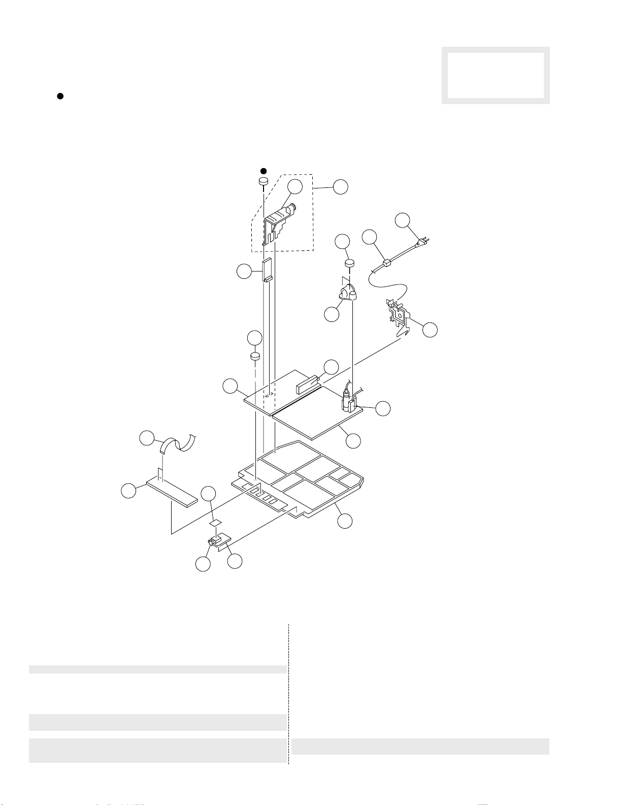
7-2. CHASSIS
: 7-685-648-79 +BVTP 3X12
The components identified by
shading and mark
cal for safety.
Replace only with part number
specified.
¡ are criti-
51
60
62
61
64
65
59
63
66
69
68
67
58
57
52
REF. NO. PART NO. DESCRIPTION REMARK
------------ ------------- ------------------- ------------51 1-777-353-11 CABLE, FLAT
52 * A-1372-257-A H3 BOARD, COMPLETE
53 * 4-055-447-21 SHEET, INSULATING
54 ¡ 1-571-433-21 SWITCH, PUSH (AC POWER)
55 * A-1241-319-A F1 BOARD, COMPLETE
56 * X-4034-588-4 BRACKET ASSY, MAIN
57 * A-1346-699-A D BOARD, COMPLETE (J29MF8J)
* A-1346-700-A D BOARD, COMPLETE (J25MF8J)
58 ¡ 1-453-227-11 TRANSFORMER ASSY, FLYBACK
¡ 1-453-227-21 TRANSFORMER ASSY, FLYBACK
59 ¡ 8-598-375-01 TUNER VSS BTV-FG411
53
54
(NX-4002//M3I4) (J25MF8J)
(NX-4002//M3I4) (J29MF8J)
55
56
REF. NO. PART NO. DESCRIPTION REMARK
------------ ------------- ------------------- ------------60 * A-1298-389-A A BOARD, COMPLETE (J29MF8J)
*A-1298-390-A A BOARD, COMPLETE (J25MF8J)
61 4-046-797-01 SCREW (3X12), (+)BVTAP
62 * A-1390-802-A S1 BOARD, COMPLETE
63 X-4034-323-1 HOLDER ASSY, PWB (J29MF8J) 64
64 * 4-055-142-02 HOLDER, PC BOARD
65 * 4-055-139-01 HOLDER, FBT
66 4-302-428-03 SCREW (WASHER HEAD) (+P 3X12)
67 4-055-143-11 BRACKET, TERMINAL
68 4-022-115-00 HOLDER, AC CORD
69 ¡ 1-574-062-12 CORD, POWER (WITH CONNECTOR)
2.5A/250V
– 60 –

The components identified by
shading and mark
cal for safety.
Replace only with part number
specified.
NOTE:
REF. NO. PART NO. DESCRIPTION REMARK
------------ ------------- ------------------- -------------
The components identified by
shading and mark
cal for safety.
Replace only with part number
specified.
REF. NO. PART NO. DESCRIPTION REMARK
------------ ------------- ------------------- -------------
CN1690 * 1-580-844-11 PIN, CONNECTOR (POWER)
CN1691 * 1-695-292-11 PIN, CONNECTOR (POWER)
F1690 ¡ 1-532-350-11 FUSE, TIME-LAG 4A/250V
S1690 ¡ 1-571-433-21 SWITCH, PUSH (AC POWER)
*************************************************************
C001 1-163-011-11 CERAMIC CHIP 0.0015MF 10% 50V
C002 1-126-965-11 ELECT 22MF 20% 50V
C003 1-163-251-11 CERAMIC CHIP 100PF 5% 50V
C004 1-126-961-11 ELECT 2.2MF 20% 50V
C005 1-163-251-11 CERAMIC CHIP 100PF 5% 50V
C006 1-163-251-11 CERAMIC CHIP 100PF 5% 50V
C007 1-124-902-00 ELECT 0.47MF 20% 50V
C008 1-163-251-11 CERAMIC CHIP 100PF 5% 50V
C009 1-163-275-11 CERAMIC CHIP 0.001MF 5% 50V
C010 1-163-037-11 CERAMIC CHIP 0.022MF 10% 50V
C011 1-163-251-11 CERAMIC CHIP 100PF 5% 50V
C012 1-163-251-11 CERAMIC CHIP 100PF 5% 50V
C013 1-163-251-11 CERAMIC CHIP 100PF 5% 50V
C014 1-163-275-11 CERAMIC CHIP 0.001MF 5% 50V
C015 1-101-884-00 CERAMIC 56PF 5% 50V
C016 1-101-884-00 CERAMIC 56PF 5% 50V
C017 1-163-251-11 CERAMIC CHIP 100PF 5% 50V
C018 1-163-099-00 CERAMIC CHIP 18PF 5% 50V
C019 1-163-275-11 CERAMIC CHIP 0.001MF 5% 50V
C020 1-163-259-91 CERAMIC CHIP 220PF 5% 50V
C021 1-163-275-11 CERAMIC CHIP 0.001MF 5% 50V
C022 1-124-122-11 ELECT 100MF 20% 50V
C023 1-163-275-11 CERAMIC CHIP 0.001MF 5% 50V
C024 1-163-259-91 CERAMIC CHIP 220PF 5% 50V
¡ are criti-
¡ are criti-
*A-1241-319-A F1 BOARD, COMPLETE
1-533-223-11 HOLDER, FUSE ; F1690
*A-1298-389-A A BOARD, COMPLETE (KV-J29MF8J)
*A-1298-390-A A BOARD, COMPLETE (KV-J25MF8J)
*4-049-131-01 CASE (A), SHIELD
4-382-854-11 SCREW (M3X10), P, SW (+)
Les composants identifies par
une trame et une marque
sont critiques pour la securite.
Ne les remplacer que par une
piece portant le numero specifie.
• The components identified by in this manual
have been carefully factory-selected for each set
in order to satisfy regulations regarding X-ray
radiation. Should replacement be required,
replace only with the value originally used.
• Items marked " * " are not stocked since they are
seldom required for routine service. Some delay
should be anticipated when ordering these items.
• All variable and adjustable resistors have
characteristic curve B, unless otherwise noted.
RESISTORS
• All resistors are in ohms
• F : nonflammable
**********************
<CONNECTOR>
<FUSE>
<SWITCH>
*********************
*********************
<CAPACITOR>
SECTION 8
¡
ELECTRICAL PARTS LIST
(f1)(a)
------------------------------------------------------------------------------------------------------------------------------REF. NO. PART NO. DESCRIPTION REMARK
------------ ------------- ------------------- -------------
REF. NO. PART NO. DESCRIPTION REMARK
------------ ------------- ------------------- ------------ C025 1-163-275-11 CERAMIC CHIP 0.001MF 5% 50V
C026 1-163-251-11 CERAMIC CHIP 100PF 5% 50V
C027 1-163-251-11 CERAMIC CHIP 100PF 5% 50V
C028 1-163-259-91 CERAMIC CHIP 220PF 5% 50V
C029 1-163-259-91 CERAMIC CHIP 220PF 5% 50V
C030 1-163-037-11 CERAMIC CHIP 0.022MF 10% 50V
C031 1-163-243-11 CERAMIC CHIP 47PF 5% 50V
C032 1-163-259-91 CERAMIC CHIP 220PF 5% 50V
C033 1-164-505-11 CERAMIC CHIP 2.2MF 16V
C034 1-164-004-11 CERAMIC CHIP 0.1MF 10% 25V
C035 1-163-009-11 CERAMIC CHIP 0.001MF 10% 50V
C037 1-163-259-91 CERAMIC CHIP 220PF 5% 50V
C038 1-124-122-11 ELECT 100MF 20% 50V
C039 1-163-251-11 CERAMIC CHIP 100PF 5% 50V
C040 1-163-251-11 CERAMIC CHIP 100PF 5% 50V
C041 1-164-004-11 CERAMIC CHIP 0.1MF 10% 25V
------------------------------------------------------------------------------------------------------------------------------ C042 1-163-251-11 CERAMIC CHIP 100PF 5% 50V
C043 1-163-251-11 CERAMIC CHIP 100PF 5% 50V
C044 1-163-251-11 CERAMIC CHIP 100PF 5% 50V
C045 1-216-295-91 SHORT 0
C046 1-163-251-11 CERAMIC CHIP 100PF 5% 50V
C048 1-163-251-11 CERAMIC CHIP 100PF 5% 50V
C049 1-163-251-11 CERAMIC CHIP 100PF 5% 50V
C050 1-163-251-11 CERAMIC CHIP 100PF 5% 50V
C051 1-163-251-11 CERAMIC CHIP 100PF 5% 50V
C052 1-164-004-11 CERAMIC CHIP 0.1MF 10% 25V
C053 1-164-004-11 CERAMIC CHIP 0.1MF 10% 25V
C054 1-164-232-11 CERAMIC CHIP 0.01MF 10% 50V
C055 1-126-941-11 ELECT 470MF 20% 16V
C056 1-163-011-11 CERAMIC CHIP 0.0015MF 10% 50V
C057 1-163-001-11 CERAMIC CHIP 220PF 10% 50V
C064 1-163-037-11 CERAMIC CHIP 0.022MF 10% 50V
C065 1-163-259-91 CERAMIC CHIP 220PF 5% 50V
C066 1-163-259-91 CERAMIC CHIP 220PF 5% 50V
C067 1-163-259-91 CERAMIC CHIP 220PF 5% 50V
C068 1-163-259-91 CERAMIC CHIP 220PF 5% 50V
C069 1-163-259-91 CERAMIC CHIP 220PF 5% 50V
C072 1-126-941-11 ELECT 470MF 20% 16V
C074 1-163-001-11 CERAMIC CHIP 220PF 10% 50V
C078 1-104-665-11 ELECT 100MF 20% 16V
C079 1-136-165-00 FILM 0.1MF 5% 50V
C080 1-164-232-11 CERAMIC CHIP 0.01MF 10% 50V
C082 1-164-232-11 CERAMIC CHIP 0.01MF 10% 50V
C083 1-164-232-11 CERAMIC CHIP 0.01MF 10% 50V
C084 1-164-232-11 CERAMIC CHIP 0.01MF 10% 50V
C085 1-164-232-11 CERAMIC CHIP 0.01MF 10% 50V
C086 1-164-232-11 CERAMIC CHIP 0.01MF 10% 50V
C087 1-164-232-11 CERAMIC CHIP 0.01MF 10% 50V
C088 1-164-232-11 CERAMIC CHIP 0.01MF 10% 50V
------------------ C089 1-164-232-11 CERAMIC CHIP 0.01MF 10% 50V
C091 1-104-664-11 ELECT 47MF 20% 25V
C093 1-104-664-11 ELECT 47MF 20% 25V
C101 1-124-903-11 ELECT 1MF 20% 50V
When indicating parts by reference number,
please include the board name.
• CAPACITORS
PF : µµ F
• There are some cases the reference number on
one board overlaps on the other board. Therefore,
when ordering parts by the reference number,
please include the board name.
– 61 –

(a)
REF. NO. PART NO. DESCRIPTION REMARK
------------ ------------- ------------------- ------------ C102 1-164-161-11 CERAMIC CHIP 0.0022MF 10% 50V
C103 1-104-760-11 CERAMIC CHIP 0.047MF 10% 50V
C105 1-163-005-11 CERAMIC CHIP 470PF 10% 50V
C105 1-164-343-11 CERAMIC CHIP 0.056MF 10% 25V
C106 1-164-232-11 CERAMIC CHIP 0.01MF 10% 50V
C107 1-163-251-11 CERAMIC CHIP 100PF 5% 50V
C108 1-124-557-11 ELECT 1000MF 20% 25V
C109 1-163-017-00 CERAMIC CHIP 0.0047MF 10% 50V
C114 1-163-251-11 CERAMIC CHIP 100PF 5% 50V
C115 1-163-227-11 CERAMIC CHIP 10PF 0.5PF 50V
C116 1-136-165-00 FILM 0.1MF 5% 50V
C117 1-163-251-11 CERAMIC CHIP 100PF 5% 50V
C118 1-126-965-11 ELECT 22MF 20% 50V
C119 1-163-031-11 CERAMIC CHIP 0.01MF 50V
C120 1-130-493-00 MYLAR 0.068MF 5% 50V
C121 1-130-493-00 MYLAR 0.068MF 5% 50V
C122 1-104-665-11 ELECT 100MF 20% 16V
C129 1-136-173-00 FILM 0.47MF 5% 50V
C130 1-124-903-11 ELECT 1MF 20% 50V
C133 1-104-664-11 ELECT 47MF 20% 25V
C134 1-164-232-11 CERAMIC CHIP 0.01MF 10% 50V
C135 1-124-902-00 ELECT 0.47MF 20% 50V
C136 1-164-005-11 CERAMIC CHIP 0.47MF 25V
C137 1-163-133-00 CERAMIC CHIP 470PF 5% 50V
C138 1-124-907-11 ELECT 10MF 20% 50V
C139 1-163-231-11 CERAMIC CHIP 15PF 5% 50V
C140 1-124-907-11 ELECT 10MF 20% 50V
C141 1-163-099-00 CERAMIC CHIP 18PF 5% 50V
C142 1-124-902-00 ELECT 0.47MF 20% 50V
C143 1-124-907-11 ELECT 10MF 20% 50V
C145 1-124-907-11 ELECT 10MF 20% 50V
C146 1-163-251-11 CERAMIC CHIP 100PF 5% 50V
C147 1-164-232-11 CERAMIC CHIP 0.01MF 10% 50V
C148 1-164-346-11 CERAMIC CHIP 1MF 16V
C149 1-164-346-11 CERAMIC CHIP 1MF 16V
C150 1-164-346-11 CERAMIC CHIP 1MF 16V
C151 1-164-232-11 CERAMIC CHIP 0.01MF 10% 50V
C152 1-104-664-11 ELECT 47MF 20% 25V
C153 1-164-232-11 CERAMIC CHIP 0.01MF 10% 50V
C154 1-126-961-11 ELECT 2.2MF 20% 50V
C155 1-164-232-11 CERAMIC CHIP 0.01MF 10% 50V
C156 1-163-017-00 CERAMIC CHIP 0.0047MF 10% 50V
C157 1-164-232-11 CERAMIC CHIP 0.01MF 10% 50V
C158 1-163-017-00 CERAMIC CHIP 0.0047MF 10% 50V
C159 1-164-232-11 CERAMIC CHIP 0.01MF 10% 50V
C160 1-164-346-11 CERAMIC CHIP 1MF 16V
C162 1-104-666-11 ELECT 220MF 20% 16V
C163 1-164-346-11 CERAMIC CHIP 1MF 16V
C164 1-137-581-11 FILM 0.1MF 5% 100V
C165 1-164-346-11 CERAMIC CHIP 1MF 16V
C166 1-137-581-11 FILM 0.1MF 5% 100V
C167 1-104-664-11 ELECT 47MF 20% 25V
C168 1-164-232-11 CERAMIC CHIP 0.01MF 10% 50V
C169 1-137-372-11 FILM 0.022MF 5% 50V
C170 1-163-009-11 CERAMIC CHIP 0.001MF 10% 50V
C187 1-137-372-11 FILM 0.022MF 5% 50V
C189 1-126-965-11 ELECT 22MF 20% 50V
C191 1-137-372-11 FILM 0.022MF 5% 50V
C192 1-126-961-11 ELECT 2.2MF 20% 50V
C195 1-136-173-00 FILM 0.47MF 5% 50V
C198 1-163-009-11 CERAMIC CHIP 0.001MF 10% 50V
C199 1-164-004-11 CERAMIC CHIP 0.1MF 10% 25V
C200 1-164-232-11 CERAMIC CHIP 0.01MF 10% 50V
C206 1-164-004-11 CERAMIC CHIP 0.1MF 10% 25V
C207 1-164-004-11 CERAMIC CHIP 0.1MF 10% 25V
C209 1-164-004-11 CERAMIC CHIP 0.1MF 10% 25V
(J25MF8J)
(J29MF8J)
(J25MF8J)
Les composants identifies par
une trame et une marque
sont critiques pour la securite.
Ne les remplacer que par une
piece portant le numero specifie.
------------------------------------------------------------------------------------------------------------------------------REF. NO. PART NO. DESCRIPTION REMARK
------------ ------------- ------------------- ------------ C210 1-107-823-11 CERAMIC CHIP 0.47MF 10% 16V
C211 1-107-823-11 CERAMIC CHIP 0.47MF 10% 16V
C212 1-104-665-11 ELECT 100MF 20% 16V
C213 1-124-907-11 ELECT 10MF 20% 50V
C214 1-130-495-00 MYLAR 0.1MF 5% 50V
C216 1-104-661-91 ELECT 330MF 20% 16V
C217 1-164-005-11 CERAMIC CHIP 0.47MF 25V
C219 1-104-664-11 ELECT 47MF 20% 25V
C220 1-164-004-11 CERAMIC CHIP 0.1MF 10% 25V
C223 1-164-161-11 CERAMIC CHIP 0.22MF 10% 25V
C224 1-164-161-11 CERAMIC CHIP 0.22MF 10% 25V
C237 1-124-903-11 ELECT 1MF 20% 50V
C238 1-124-903-11 ELECT 1MF 20% 50V
C240 1-124-903-11 ELECT 1MF 20% 50V
C241 1-128-550-11 ELECT 2200MF 20% 35V
C242 1-164-232-11 CERAMIC CHIP 0.01MF 10% 50V
C243 1-126-965-11 ELECT 22MF 20% 50V
C244 1-128-550-11 ELECT 2200MF 20% 35V
C245 1-130-495-00 MYLAR 0.1MF 5% 50V
C246 1-126-965-11 ELECT 22MF 20% 50V
C247 1-128-550-11 ELECT 2200MF 20% 35V
C248 1-130-495-00 MYLAR 0.1MF 5% 50V
C249 1-104-661-91 ELECT 330MF 20% 16V
C250 1-104-661-91 ELECT 330MF 20% 16V
C251 1-124-910-11 ELECT 47MF 20% 50V
C257 1-247-843-11 CARBON 3.3K 5% 1/4W
C258 1-247-843-11 CARBON 3.3K 5% 1/4W
C260 1-163-037-11 CERAMIC CHIP 0.022MF 10% 50V
C261 1-163-037-11 CERAMIC CHIP 0.022MF 10% 50V
C264 1-163-017-00 CERAMIC CHIP 0.0047MF 10% 50V
C265 1-164-346-11 CERAMIC CHIP 1MF 16V
-------------------------------------------------------------------------------------------------------------------------------
C266 1-164-346-11 CERAMIC CHIP 1MF 16V
C267 1-163-809-11 CERAMIC CHIP 0.047MF 10% 25V
C268 1-104-665-11 ELECT 100MF 20% 16V
C269 1-163-017-00 CERAMIC CHIP 0.0047MF 10% 50V
C270 1-163-809-11 CERAMIC CHIP 0.047MF 10% 25V
C325 1-216-055-00 RES, CHIP 1.8K
C326 1-216-055-00 RES, CHIP 1.8K
C327 1-216-055-00 RES, CHIP 1.8K
C367 1-104-664-11 ELECT 47MF 20% 25V
C370 1-164-004-11 CERAMIC CHIP 0.1MF 10% 25V
C374 1-124-910-11 ELECT 47MF 20% 50V
C375 1-124-910-11 ELECT 47MF 20% 50V
C420 1-104-664-11 ELECT 47MF 20% 25V
C1201 1-163-031-11 CERAMIC CHIP 0.01MF 50V
C1203 1-104-664-11 ELECT 47MF 20% 25V
C1204 1-104-665-11 ELECT 100MF 20% 16V
C1205 1-164-005-11 CERAMIC CHIP 0.47MF 25V
C1206 1-164-005-11 CERAMIC CHIP 0.47MF 25V
C1207 1-126-966-11 ELECT 33MF 20% 50V
C1208 1-104-664-11 ELECT 47MF 20% 25V
C1209 1-104-664-11 ELECT 47MF 20% 25V
C1210 1-104-664-11 ELECT 47MF 20% 25V
C1213 1-163-251-11 CERAMIC CHIP 100PF 5% 50V
C1214 1-163-009-11 CERAMIC CHIP 0.001MF 10% 50V
C1215 1-164-346-11 CERAMIC CHIP 1MF 16V
C1216 1-163-009-11 CERAMIC CHIP 0.001MF 10% 50V
C1217 1-164-346-11 CERAMIC CHIP 1MF 16V
C1218 1-104-664-11 ELECT 47MF 20% 25V
C1219 1-163-031-11 CERAMIC CHIP 0.01MF 50V
C1220 1-104-664-11 ELECT 47MF 20% 25V
C1226 1-164-346-11 CERAMIC CHIP 1MF 16V
C1227 1-164-346-11 CERAMIC CHIP 1MF 16V
C1228 1-126-941-11 ELECT 470MF 20% 16V
------------------ C1229 1-164-346-11 CERAMIC CHIP 1MF 16V
C1230 1-164-346-11 CERAMIC CHIP 1MF 16V
C1231 1-104-664-11 ELECT 47MF 20% 25V
C1232 1-164-346-11 CERAMIC CHIP 1MF 16V
¡
The components identified by
shading and mark
cal for safety.
Replace only with part number
specified.
¡ are criti-
– 62 –

The components identified by
shading and mark
cal for safety.
Replace only with part number
specified.
REF. NO. PART NO. DESCRIPTION REMARK
------------ ------------- ------------------- ------------ C1233 1-164-346-11 CERAMIC CHIP 1MF 16V
C1234 1-104-664-11 ELECT 47MF 20% 25V
C1242 1-216-295-91 SHORT 0
C1243 1-216-295-91 SHORT 0
C1246 1-104-664-11 ELECT 47MF 20% 25V
C1250 1-163-133-00 CERAMIC CHIP 470PF 5% 50V
C1251 1-163-133-00 CERAMIC CHIP 470PF 5% 50V
C1252 1-163-133-00 CERAMIC CHIP 470PF 5% 50V
C1253 1-163-133-00 CERAMIC CHIP 470PF 5% 50V
C1254 1-163-133-00 CERAMIC CHIP 470PF 5% 50V
C1255 1-163-133-00 CERAMIC CHIP 470PF 5% 50V
C1256 1-163-133-00 CERAMIC CHIP 470PF 5% 50V
C1257 1-163-133-00 CERAMIC CHIP 470PF 5% 50V
C1258 1-163-251-11 CERAMIC CHIP 100PF 5% 50V
C1259 1-163-251-11 CERAMIC CHIP 100PF 5% 50V
CN102 1-569-321-11 SOCKET, CONNECTOR 15P
CN103 1-569-321-11 SOCKET, CONNECTOR 15P
CN106 * 1-779-891-11 CONNECTOR, BOARD TO BOARD 8P
CN107 * 1-779-891-11 CONNECTOR, BOARD TO BOARD 8P
CN108 * 1-779-891-11 CONNECTOR, BOARD TO BOARD 8P
CN109 * 1-779-892-11 CONNECTOR, BOARD TO BOARD 10P
CN117 * 1-564-509-11 PLUG, CONNECTOR 6P
CN118 * 1-560-278-21 PLUG, CONNECTOR 4P
CN120 * 1-564-506-11 PLUG, CONNECTOR 3P
CN121 * 1-770-747-11 CONNECTOR, BOARD TO BOARD 12P
CN127 1-695-915-11 TAB (CONTACT)
CN128 1-770-722-11 CONNECTOR, BOARD TO BOARD 6P
D001 8-719-109-81 DIODE RD4.7ESB2
D002 8-719-988-62 DIODE 1SS355
D005 8-719-908-03 DIODE GP08D
D101 8-719-911-19 DIODE 1SS119-25
D102 1-249-431-11 CARBON 15K 5% 1/4W
D103 8-719-988-62 DIODE 1SS355
D104 8-719-914-43 DIODE DAN202K
D105 8-719-988-62 DIODE 1SS355
D106 8-719-157-36 DIODE RD6.8M-B
D107 8-719-106-31 DIODE RD8.2M-T1B1
D111 8-719-110-22 DIODE RD11ESB2
D112 8-719-106-43 DIODE RD9.1M-B1
D117 8-719-400-75 DIODE MA3091
D210 8-719-911-19 DIODE 1SS119-25
D211 8-719-404-49 DIODE MA111
D212 8-719-404-49 DIODE MA111
D218 8-719-914-43 DIODE DAN202K
D220 8-719-109-88 DIODE RD5.6ESB1
D352 8-719-109-84 DIODE RD5.1ESB1
D353 8-719-908-03 DIODE GP08D
D1201 8-719-121-24 DIODE RD9.1ESL
D1202 8-719-121-24 DIODE RD9.1ESL
D1203 8-719-121-24 DIODE RD9.1ESL
D1204 8-719-121-24 DIODE RD9.1ESL
D1205 8-719-121-24 DIODE RD9.1ESL
D1208 8-719-121-24 DIODE RD9.1ESL
D1209 8-719-121-24 DIODE RD9.1ESL
D1210 8-719-121-24 DIODE RD9.1ESL
D1211 8-719-121-24 DIODE RD9.1ESL
D1212 8-719-121-24 DIODE RD9.1ESL
D1213 8-719-121-24 DIODE RD9.1ESL
D1214 8-719-121-24 DIODE RD9.1ESL
D1215 8-719-121-24 DIODE RD9.1ESL
D1216 8-719-121-24 DIODE RD9.1ESL
D1220 8-719-121-24 DIODE RD9.1ESL
¡ are criti-
Les composants identifies par
une trame et une marque
sont critiques pour la securite.
Ne les remplacer que par une
piece portant le numero specifie.
<CONNECTOR>
<DIODE>
¡
(J25MF8J)
(a)
------------------------------------------------------------------------------------------------------------------------------REF. NO. PART NO. DESCRIPTION REMARK
------------ ------------- ------------------- -------------
<DELAY LINE>
DL300 1-409-547-11 DELAY LINE
<IC>
IC001 8-752-890-83 IC CXP85332A-238S
IC002 8-759-805-37 IC L78LR05D-MA
IC003 8-759-370-33 IC ST24C04FB6
IC102 8-759-157-40 IC uPC574J
IC104 8-752-076-87 IC CXA2050S
IC201 8-759-095-63 IC PQ09RF2
IC203 8-759-168-24 IC TA8200AH
IC205 8-759-231-58 IC TA7812S
IC206 8-759-090-21 IC TDA8424
IC351 8-759-288-85 IC TDA4665T-T
IC354 8-759-251-56 IC TDA8395T
IC1201 8-752-068-46 IC CXA1855S
<JACK>
J1202 1-778-388-11 JACK BLOCK, PIN 9P
<CHIP CONDUCTOR>
JR001 1-216-295-91 SHORT 0
JR005 1-216-295-91 SHORT 0
JR006 1-216-295-91 SHORT 0
JR007 1-216-295-91 SHORT 0
JR008 1-216-295-91 SHORT 0
JR009 1-216-295-91 SHORT 0
-------------------------------------------------------------------------------------------------------------------------------
JR010 1-216-295-91 SHORT 0
JR011 1-216-295-91 SHORT 0
JR012 1-216-295-91 SHORT 0
JR013 1-216-295-91 SHORT 0
JR023 1-216-295-91 SHORT 0
JR024 1-216-295-91 SHORT 0
JR025 1-216-295-91 SHORT 0
JR027 1-216-295-91 SHORT 0
JR028 1-216-295-91 SHORT 0
JR029 1-216-295-91 SHORT 0
JR030 1-216-295-91 SHORT 0
JR031 1-216-295-91 SHORT 0
JR032 1-216-295-91 SHORT 0
JR081 1-216-295-91 SHORT 0
JR083 1-216-295-91 SHORT 0
JR087 1-216-295-91 SHORT 0
JR205 1-216-295-91 SHORT 0
JR206 1-216-295-91 SHORT 0
<COIL>
L001 1-408-397-00 INDUCTOR 1UH
L002 1-408-409-00 INDUCTOR 10UH
L003 1-408-605-31 INDUCTOR 15UH
L004 1-408-409-00 INDUCTOR 10UH
L010 1-410-663-31 INDUCTOR 10UH
L080 1-408-409-00 INDUCTOR 10UH
L082 1-408-409-00 INDUCTOR 10UH
L108 1-408-409-00 INDUCTOR 10UH
L109 1-408-421-00 INDUCTOR 100UH
L110 1-408-409-00 INDUCTOR 10UH
L1201 1-408-412-00 INDUCTOR 18UH
-------------------
Q001 8-729-216-22 TRANSISTOR 2SA1162-G
Q030 8-729-230-49 TRANSISTOR 2SC2712-YG-TE85L
Q031 8-729-216-22 TRANSISTOR 2SA1162-G
Q033 8-729-901-06 TRANSISTOR DTA144EK
<TRANSISTOR>
– 63 –

(a)
REF. NO. PART NO. DESCRIPTION REMARK
------------ ------------- ------------------- ------------ Q105 8-729-027-43 TRANSISTOR DTC114EKA-T146
Q106 8-729-216-22 TRANSISTOR 2SA1162-G
Q108 8-729-027-43 TRANSISTOR DTC114EKA-T146
Q109 8-729-230-49 TRANSISTOR 2SC2712-YG-TE85L
Q110 8-729-230-49 TRANSISTOR 2SC2712-YG-TE85L
Q111 8-729-230-49 TRANSISTOR 2SC2712-YG-TE85L
Q112 8-729-027-43 TRANSISTOR DTC114EKA-T146
Q113 8-729-230-49 TRANSISTOR 2SC2712-YG-TE85L
Q205 1-801-806-11 TRANSISTOR DTC144EK-T146
Q209 1-801-806-11 TRANSISTOR DTC144EK-T146
Q210 1-801-806-11 TRANSISTOR DTC144EK-T146
Q211 8-729-216-22 TRANSISTOR 2SA1162-G
Q306 8-729-230-49 TRANSISTOR 2SC2712-YG-TE85L
Q315 8-729-230-49 TRANSISTOR 2SC2712-YG-TE85L
Q320 8-729-230-49 TRANSISTOR 2SC2712-YG-TE85L
Q352 8-729-230-49 TRANSISTOR 2SC2712-YG-TE85L
Q354 8-729-230-49 TRANSISTOR 2SC2712-YG-TE85L
Q1201 8-729-230-49 TRANSISTOR 2SC2712-YG-TE85L
Q1202 8-729-230-49 TRANSISTOR 2SC2712-YG-TE85L
Q1203 8-729-230-49 TRANSISTOR 2SC2712-YG-TE85L
Q1204 8-729-216-22 TRANSISTOR 2SA1162-G
Q1205 8-729-230-49 TRANSISTOR 2SC2712-YG-TE85L
Q1206 8-729-230-49 TRANSISTOR 2SC2712-YG-TE85L
<RESISTOR>
R001 1-216-065-00 RES, CHIP 4.7K
R002 1-216-065-00 RES, CHIP 4.7K
R003 1-216-065-00 RES, CHIP 4.7K
R004 1-216-065-00 RES, CHIP 4.7K
R005 1-216-025-91 RES, CHIP 100
R006 1-216-025-91 RES, CHIP 100
R007 1-216-073-00 RES, CHIP 10K
R008 1-216-049-91 RES, CHIP 1.0K
R009 1-216-049-91 RES, CHIP 1.0K
R010 1-216-049-91 RES, CHIP 1.0K
R011 1-216-049-91 RES, CHIP 1.0K
R013 1-216-049-91 RES, CHIP 1.0K
R014 1-216-049-91 RES, CHIP 1.0K
R015 1-216-049-91 RES, CHIP 1.0K
R016 1-216-049-91 RES, CHIP 1.0K
R018 1-216-033-00 RES, CHIP 220
R019 1-216-101-00 RES, CHIP 150K
R020 1-216-025-91 RES, CHIP 100
R026 1-216-049-91 RES, CHIP 1.0K
R028 1-216-025-91 RES, CHIP 100
R029 1-216-065-00 RES, CHIP 4.7K
R030 1-216-097-91 RES, CHIP 100K
R031 1-216-049-91 RES, CHIP 1.0K
R032 1-216-065-00 RES, CHIP 4.7K (J29MF8J)
R033 1-216-049-91 RES, CHIP 1.0K
R035 1-216-065-00 RES, CHIP 4.7K
R036 1-216-065-00 RES, CHIP 4.7K (J29MF8J)
R038 1-216-051-00 RES, CHIP 1.2K
R039 1-216-025-91 RES, CHIP 100
R040 1-216-051-00 RES, CHIP 1.2K
R041 1-216-025-91 RES, CHIP 100
R042 1-216-051-00 RES, CHIP 1.2K
R043 1-216-081-00 RES, CHIP 22K
R044 1-216-073-00 RES, CHIP 10K
R046 1-216-025-91 RES, CHIP 100
R047 1-216-025-91 RES, CHIP 100
R048 1-216-025-91 RES, CHIP 100
R049 1-216-121-91 RES, CHIP 1.0M
R050 1-216-057-00 RES, CHIP 2.2K
R053 1-216-025-91 RES, CHIP 100
R054 1-216-073-00 RES, CHIP 10K
R055 1-216-095-00 RES, CHIP 82K
R056 1-216-025-91 RES, CHIP 100
Les composants identifies par
une trame et une marque
sont critiques pour la securite.
Ne les remplacer que par une
piece portant le numero specifie.
------------------------------------------------------------------------------------------------------------------------------REF. NO. PART NO. DESCRIPTION REMARK
------------ ------------- ------------------- ------------ R057 1-216-049-91 RES, CHIP 1.0K
R058 1-216-049-91 RES, CHIP 1.0K
R059 1-216-065-00 RES, CHIP 4.7K
R061 1-216-025-91 RES, CHIP 100
R062 1-216-025-91 RES, CHIP 100
R063 1-216-025-91 RES, CHIP 100
R064 1-216-025-91 RES, CHIP 100
R065 1-216-065-00 RES, CHIP 4.7K
R066 1-216-065-00 RES, CHIP 4.7K
R069 1-216-049-91 RES, CHIP 1.0K
R070 1-216-033-00 RES, CHIP 220
R071 1-216-033-00 RES, CHIP 220
R072 1-216-073-00 RES, CHIP 10K
R073 1-216-073-00 RES, CHIP 10K
R074 1-216-079-00 RES, CHIP 18K
R075 1-216-073-00 RES, CHIP 10K
R076 1-216-025-91 RES, CHIP 100
R077 1-216-025-91 RES, CHIP 100
R078 1-216-073-00 RES, CHIP 10K
R081 1-216-049-91 RES, CHIP 1.0K
R090 1-216-073-00 RES, CHIP 10K
R101 1-216-065-00 RES, CHIP 4.7K
R102 1-216-025-91 RES, CHIP 100
R103 1-216-041-00 RES, CHIP 470
R104 1-216-077-00 RES, CHIP 15K
R105 1-216-025-91 RES, CHIP 100
R106 1-216-049-91 RES, CHIP 1.0K
R107 1-216-033-00 RES, CHIP 220
R108 1-216-049-91 RES, CHIP 1.0K
R109 1-216-033-00 RES, CHIP 220
R110 1-216-049-91 RES, CHIP 1.0K
-------------------------------------------------------------------------------------------------------------------------------
R111 1-216-033-00 RES, CHIP 220
R112 1-216-025-91 RES, CHIP 100
R113 1-216-081-00 RES, CHIP 22K
R114 1-216-041-00 RES, CHIP 470
R115 1-216-081-00 RES, CHIP 22K
R116 1-216-081-00 RES, CHIP 22K
R117 1-216-081-00 RES, CHIP 22K
R118 1-216-081-00 RES, CHIP 22K
R119 1-216-055-00 RES, CHIP 1.8K
R120 1-216-109-00 RES, CHIP 330K
R121 1-208-806-11 RES, CHIP 10K
R122 1-216-033-00 RES, CHIP 220
R123 1-216-065-00 RES, CHIP 4.7K
R124 1-216-025-91 RES, CHIP 100
R125 1-216-025-91 RES, CHIP 100
R126 1-216-025-91 RES, CHIP 100
R128 1-216-033-00 RES, CHIP 220
R129 1-216-041-00 RES, CHIP 470
R130 1-216-025-91 RES, CHIP 100
R132 1-216-033-00 RES, CHIP 220
R133 1-216-025-91 RES, CHIP 100
R135 1-216-295-91 SHORT 0
R138 1-216-025-91 RES, CHIP 100
R139 1-216-049-91 RES, CHIP 1.0K
R141 1-216-109-00 RES, CHIP 330K (J25MF8J)
R142 1-216-049-91 RES, CHIP 1.0K
R143 1-216-041-00 RES, CHIP 470
R144 1-216-053-00 RES, CHIP 1.5K
R145 1-216-061-00 RES, CHIP 3.3K
R146 1-216-025-91 RES, CHIP 100
R148 1-216-105-91 RES, CHIP 220K
R149 1-216-041-00 RES, CHIP 470
R150 1-216-041-00 RES, CHIP 470
------------------ R151 1-216-043-91 RES, CHIP 560
R152 1-216-065-00 RES, CHIP 4.7K (J25MF8J)
R153 1-216-295-91 SHORT 0
R154 1-216-031-00 RES, CHIP 180
R155 1-216-295-91 SHORT 0
¡
The components identified by
shading and mark
cal for safety.
Replace only with part number
specified.
¡ are criti-
– 64 –

The components identified by
shading and mark
cal for safety.
Replace only with part number
specified.
REF. NO. PART NO. DESCRIPTION REMARK
------------ ------------- ------------------- ------------ R156 1-216-031-00 RES, CHIP 180
R157 1-216-295-91 SHORT 0
R158 1-216-031-00 RES, CHIP 180
R159 1-216-033-00 RES, CHIP 220
R160 1-216-073-00 RES, CHIP 10K
R164 1-216-099-00 RES, CHIP 120K (J25MF8J)
R170 1-216-037-00 RES, CHIP 330
R171 1-216-081-00 RES, CHIP 22K
R172 1-216-097-91 RES, CHIP 100K
R173 1-216-081-00 RES, CHIP 22K (J25MF8J)
R174 1-216-105-91 RES, CHIP 220K (J29MF8J)
R174 1-216-109-00 RES, CHIP 330K (J25MF8J)
R175 1-216-073-00 RES, CHIP 10K (J29MF8J)
R175 1-216-079-00 RES, CHIP 18K (J25MF8J)
R176 1-216-061-00 RES, CHIP 3.3K
R177 1-216-049-91 RES, CHIP 1.0K
R178 1-216-025-91 RES, CHIP 100
R179 1-208-291-11 RES, CHIP 4.7M (J29MF8J)
R179 1-216-119-00 RES, CHIP 820K (J25MF8J)
R180 1-216-033-00 RES, CHIP 220
R181 1-216-033-00 RES, CHIP 220
R182 1-216-033-00 RES, CHIP 220
R184 1-216-059-00 RES, CHIP 2.7K
R186 1-216-001-00 RES, CHIP 10
R191 1-216-025-91 RES, CHIP 100
R192 1-216-097-91 RES, CHIP 100K
R201 1-164-346-11 CERAMIC CHIP 1MF 16V
R202 1-164-346-11 CERAMIC CHIP 1MF 16V
R203 1-216-073-00 RES, CHIP 10K
R208 1-216-475-11 METAL OXIDE 120 5% 3W F
R209 1-216-049-91 RES, CHIP 1.0K
R210 1-216-089-91 RES, CHIP 47K
R211 1-216-049-91 RES, CHIP 1.0K
R213 1-216-073-00 RES, CHIP 10K
R214 1-216-073-00 RES, CHIP 10K
R215 1-216-089-91 RES, CHIP 47K
R217 1-216-295-91 SHORT 0
R244 1-249-413-11 CARBON 470 5% 1/4W
R245 1-216-061-00 RES, CHIP 3.3K
R246 1-216-061-00 RES, CHIP 3.3K
R252 1-249-413-11 CARBON 470 5% 1/4W
R253 1-216-386-11 METAL OXIDE 0.56 5% 3W F
R254 1-216-025-91 RES, CHIP 100
R255 1-216-308-00 RES, CHIP 4.7
R258 1-216-025-91 RES, CHIP 100
R259 1-216-308-00 RES, CHIP 4.7
R267 1-216-041-00 RES, CHIP 470
R268 1-216-025-91 RES, CHIP 100
R269 1-216-025-91 RES, CHIP 100
R270 1-216-025-91 RES, CHIP 100
R271 1-216-025-91 RES, CHIP 100
R303 1-216-001-00 RES, CHIP 10
R304 1-216-049-91 RES, CHIP 1.0K
R305 1-216-025-91 RES, CHIP 100
R306 1-216-025-91 RES, CHIP 100
R345 1-216-049-91 RES, CHIP 1.0K
R347 1-216-049-91 RES, CHIP 1.0K
R361 1-216-295-91 SHORT 0
R363 1-216-295-91 SHORT 0
R364 1-216-033-00 RES, CHIP 220
R365 1-216-025-91 RES, CHIP 100
R366 1-216-033-00 RES, CHIP 220
R368 1-216-033-00 RES, CHIP 220
R381 1-216-051-00 RES, CHIP 1.2K
R382 1-216-051-00 RES, CHIP 1.2K
R391 1-216-043-91 RES, CHIP 560
R392 1-216-295-91 SHORT 0
R801 1-216-025-91 RES, CHIP 100
R1200 1-216-033-00 RES, CHIP 220
¡ are criti-
Les composants identifies par
une trame et une marque
sont critiques pour la securite.
Ne les remplacer que par une
piece portant le numero specifie.
¡
(a)
------------------------------------------------------------------------------------------------------------------------------REF. NO. PART NO. DESCRIPTION REMARK
------------ ------------- ------------------- ------------ R1201 1-216-025-91 RES, CHIP 100
R1202 1-216-025-91 RES, CHIP 100
R1203 1-216-033-00 RES, CHIP 220
R1204 1-216-031-00 RES, CHIP 180
R1205 1-216-073-00 RES, CHIP 10K
R1206 1-216-067-00 RES, CHIP 5.6K
R1207 1-216-067-00 RES, CHIP 5.6K
R1208 1-216-025-91 RES, CHIP 100
R1209 1-216-033-00 RES, CHIP 220
R1210 1-216-031-00 RES, CHIP 180
R1211 1-216-093-00 RES, CHIP 68K
R1212 1-216-025-91 RES, CHIP 100
R1213 1-216-073-00 RES, CHIP 10K
R1214 1-216-041-00 RES, CHIP 470
R1215 1-216-025-91 RES, CHIP 100
R1216 1-216-025-91 RES, CHIP 100
R1217 1-216-025-91 RES, CHIP 100
R1218 1-216-025-91 RES, CHIP 100
R1219 1-216-025-91 RES, CHIP 100
R1220 1-216-025-91 RES, CHIP 100
R1221 1-216-073-00 RES, CHIP 10K
R1222 1-216-025-91 RES, CHIP 100
R1223 1-216-041-00 RES, CHIP 470
R1224 1-216-025-91 RES, CHIP 100
R1225 1-216-025-91 RES, CHIP 100
R1226 1-216-025-91 RES, CHIP 100
R1227 1-216-025-91 RES, CHIP 100
R1228 1-216-025-91 RES, CHIP 100
R1231 1-216-295-91 SHORT 0
R1232 1-216-033-00 RES, CHIP 220
R1233 1-216-053-00 RES, CHIP 1.5K
-------------------------------------------------------------------------------------------------------------------------------
R1234 1-216-105-91 RES, CHIP 220K
R1235 1-216-295-91 SHORT 0
R1236 1-216-295-91 SHORT 0
R1237 1-216-105-91 RES, CHIP 220K
R1239 1-216-022-00 RES, CHIP 75
R1240 1-216-022-00 RES, CHIP 75
R1241 1-216-097-91 RES, CHIP 100K
R1242 1-216-057-00 RES, CHIP 2.2K
R1243 1-216-097-91 RES, CHIP 100K
R1245 1-216-027-00 RES, CHIP 120
R1246 1-216-033-00 RES, CHIP 220
R1247 1-216-295-91 SHORT 0
R1254 1-216-113-00 RES, CHIP 470K
R1255 1-216-049-91 RES, CHIP 1.0K
R1256 1-216-113-00 RES, CHIP 470K
R1257 1-216-049-91 RES, CHIP 1.0K
R1258 1-216-113-00 RES, CHIP 470K
R1259 1-216-021-00 RES, CHIP 68
R1260 1-216-105-91 RES, CHIP 220K
R1261 1-216-065-00 RES, CHIP 4.7K
R1262 1-216-105-91 RES, CHIP 220K
R1263 1-216-065-00 RES, CHIP 4.7K
R1264 1-216-022-00 RES, CHIP 75
R1265 1-216-105-91 RES, CHIP 220K
R1266 1-216-065-00 RES, CHIP 4.7K
R1267 1-216-105-91 RES, CHIP 220K
R1268 1-216-065-00 RES, CHIP 4.7K
R1269 1-216-022-00 RES, CHIP 75
R1275 1-216-025-91 RES, CHIP 100
R1276 1-216-025-91 RES, CHIP 100
R1277 1-216-025-91 RES, CHIP 100
R1278 1-216-025-91 RES, CHIP 100
R1288 1-216-295-91 SHORT 0
------------------ R1289 1-216-295-91 SHORT 0
R1295 1-216-033-00 RES, CHIP 220
R1296 1-216-033-00 RES, CHIP 220
R1297 1-216-033-00 RES, CHIP 220
R1298 1-216-041-00 RES, CHIP 470
– 65 –

(a)(c2)
REF. NO. PART NO. DESCRIPTION REMARK
------------ ------------- ------------------- ------------ R1299 1-216-041-00 RES, CHIP 470
<TUNER>
TU001 ¡ 8-598-375-01 TUNER, VSS BTV-FG441
Les composants identifies par
une trame et une marque
sont critiques pour la securite.
Ne les remplacer que par une
piece portant le numero specifie.
------------------------------------------------------------------------------------------------------------------------------REF. NO. PART NO. DESCRIPTION REMARK
------------ ------------- ------------------- -------------
<COIL>
L701 1-410-667-31 INDUCTOR 22UH
L703 1-408-609-41 INDUCTOR 33UH
L705 1-408-609-41 INDUCTOR 33UH
L707 1-408-609-41 INDUCTOR 33UH
¡
The components identified by
shading and mark
cal for safety.
Replace only with part number
specified.
¡ are criti-
<CRYSTAL>
X101 1-577-358-21 VIBRATOR, CERAMIC
X102 1-567-505-11 OSCILLATOR, CRYSTAL
X103 1-567-504-11 OSCILLATOR, CRYSTAL
X104 1-577-611-11 OSCILALTOR, CERAMIC
<MODULE>
YCM301 1-466-162-61 FILTER BLOCK, COM (CFB-4)
*************************************************************
*A-1331-604-A C2 BOARD, COMPLETE (KV-J29MF8J)
*A-1331-625-A C2 BOARD, COMPLETE (KV-J25MF8J)
7-682-948-01 SCREW +PSW 3X8
C701 1-137-490-11 FILM 0.01MF 10% 1KV
C702 1-102-074-00 CERAMIC 0.001MF 10% 50V
C708 1-102-114-00 CERAMIC 470PF 10% 50V
C709 1-102-114-00 CERAMIC 470PF 10% 50V
C710 1-102-114-00 CERAMIC 470PF 10% 50V
C711 1-101-880-00 CERAMIC 47PF 5% 50V
C712 1-102-114-00 CERAMIC 470PF 10% 50V
C713 1-102-112-00 CERAMIC 330PF 10% 50V
C714 1-102-112-00 CERAMIC 330PF 10% 50V
C716 1-124-122-11 ELECT 100MF 20% 50V
C717 1-107-651-11 ELECT 4.7MF 20% 250V
C726 1-104-664-11 ELECT 47MF 20% 25V
CN701 * 1-508-766-00 PIN, CONNECTOR (5mm PITCH) 4P
CN703 * 1-564-509-11 PLUG, CONNECTOR 6P
CN704 1-695-915-11 TAB (CONTACT)
D701 8-719-911-19 DIODE 1SS119-25
D702 8-719-911-19 DIODE 1SS119-25
D703 8-719-911-19 DIODE 1SS119-25
D704 8-719-911-19 DIODE 1SS119-25
D705 8-719-911-19 DIODE 1SS119-25
D706 8-719-911-19 DIODE 1SS119-25
D707 8-719-911-19 DIODE 1SS119-25
D708 8-719-911-19 DIODE 1SS119-25
D709 8-719-911-19 DIODE 1SS119-25
D710 8-719-991-33 DIODE 1SS133T-77
D711 8-719-991-33 DIODE 1SS133T-77
D712 8-719-991-33 DIODE 1SS133T-77
D713 8-719-908-03 DIODE GP08D
D720 8-719-911-19 DIODE 1SS119-25
D721 8-719-911-19 DIODE 1SS119-25
J701 ¡ 1-251-239-11 SOCKET, PICTURE TUBE (J25MF8J)
J701 ¡ 1-526-990-21 SOCKET, PICTURE TUBE (J29MF8J)
**********************
**********************
<CAPACITOR>
<CONNECTOR>
<DIODE>
<JACK>
<TRANSISTOR>
Q701 8-729-326-11 TRANSISTOR 2SC2611
Q702 8-729-326-11 TRANSISTOR 2SC2611
Q703 8-729-326-11 TRANSISTOR 2SC2611
Q704 8-729-326-11 TRANSISTOR 2SC2611
Q705 8-729-326-11 TRANSISTOR 2SC2611
Q706 8-729-326-11 TRANSISTOR 2SC2611
Q707 8-729-200-17 TRANSISTOR 2SA1091-O
Q708 8-729-200-17 TRANSISTOR 2SA1091-O
Q709 8-729-200-17 TRANSISTOR 2SA1091-O
Q710 8-729-119-78 TRANSISTOR 2SC2785-HFE
Q711 8-729-119-78 TRANSISTOR 2SC2785-HFE
Q712 8-729-119-78 TRANSISTOR 2SC2785-HFE
Q713 8-729-200-17 TRANSISTOR 2SA1091-O
Q714 8-729-255-12 TRANSISTOR 2SC2551-O
<RESISTOR>
R701 1-244-941-00 CARBON 680K 5% 1/2W
R702 1-249-496-11 CARBON 100K 5% 1/2W
R703 1-249-489-11 CARBON 22K 5% 1/2W
R705 1-216-389-11 METAL OXIDE 1 5% 3W F
R710 1-215-923-00 METAL OXIDE 10K 5% 3W F
R711 1-260-101-11 CARBON 1.5K 5% 1/2W
-------------------------------------------------------------------------------------------------------------------------------
R712 1-215-923-00 METAL OXIDE 10K 5% 3W F
R713 1-260-101-11 CARBON 1.5K 5% 1/2W
R714 1-215-923-00 METAL OXIDE 10K 5% 3W F
R715 1-260-101-11 CARBON 1.5K 5% 1/2W
R716 1-249-899-11 CARBON 100 5% 1/4W F
R717 1-249-899-11 CARBON 100 5% 1/4W F
R718 1-249-899-11 CARBON 100 5% 1/4W F
R720 1-249-923-11 CARBON 1K 5% 1/4W F
R722 1-249-923-11 CARBON 1K 5% 1/4W F
R724 1-249-923-11 CARBON 1K 5% 1/4W F
R725 1-249-426-11 CARBON 5.6K 5% 1/4W
R726 1-249-426-11 CARBON 5.6K 5% 1/4W
R727 1-249-426-11 CARBON 5.6K 5% 1/4W
R728 1-249-408-11 CARBON 180 5% 1/4W
R729 1-249-408-11 CARBON 180 5% 1/4W
R730 1-247-815-91 CARBON 220 5% 1/4W
R731 1-249-401-11 CARBON 47 5% 1/4W
R732 1-249-401-11 CARBON 47 5% 1/4W
R733 1-249-401-11 CARBON 47 5% 1/4W
R734 1-260-087-11 CARBON 100 5% 1/2W
R735 1-249-417-11 CARBON 1K 5% 1/4W
R738 1-247-807-31 CARBON 100 5% 1/4W
R739 1-247-807-31 CARBON 100 5% 1/4W
R740 1-247-807-31 CARBON 100 5% 1/4W
R741 1-249-437-11 CARBON 47K 5% 1/4W
R743 1-249-435-11 CARBON 33K 5% 1/4W
R744 1-215-413-00 METAL 470 1% 1/4W
R745 1-215-413-00 METAL 470 1% 1/4W
R747 1-216-489-11 METAL OXIDE 27K 5% 3W F
R748 1-249-441-11 CARBON 100K 5% 1/4W
R749 1-216-490-11 METAL OXIDE 39K 5% 3W F
R751 1-215-926-00 METAL OXIDE 33K 5% 3W F
R753 1-249-429-11 CARBON 10K 5% 1/4W
R755 1-249-427-11 CARBON 6.8K 5% 1/4W
------------------ R756 1-249-427-11 CARBON 6.8K 5% 1/4W
R757 1-249-427-11 CARBON 6.8K 5% 1/4W
R758 1-249-419-11 CARBON 1.5K 5% 1/4W
R759 1-249-419-11 CARBON 1.5K 5% 1/4W
R760 1-249-419-11 CARBON 1.5K 5% 1/4W F
– 66 –

The components identified by
shading and mark
cal for safety.
Replace only with part number
specified.
REF. NO. PART NO. DESCRIPTION REMARK
------------ ------------- ------------------- -------------
RV701 1-230-641-11 RES, ADJ, METAL GLAZE 2.2M
RV702 1-241-656-21 RES, ADJ, METAL FILM 110M (J29MF8J)
RV704 1-247-895-91 CARBON 470K 5% 1/4W
RV705 1-247-901-11 CARBON 820K 5% 1/4W
*************************************************************
C961 1-161-830-00 CERAMIC 0.0047MF 500V
C962 1-130-491-00 MYLAR 0.047MF 5% 50V
C963 1-107-638-11 ELECT 33MF 20% 160V
C964 1-126-941-11 ELECT 470MF 20% 16V
C965 1-102-121-00 CERAMIC 0.0022MF 10% 50V
C966 1-102-121-00 CERAMIC 0.0022MF 10% 50V
C967 1-124-907-11 ELECT 10MF 20% 50V
C968 1-106-383-00 MYLAR 0.047MF 10% 200V
C969 1-107-949-11 ELECT 2.2MF 20% 160V
C970 1-104-999-11 MYLAR 0.1MF 10% 200V
C971 1-126-960-11 ELECT 1MF 20% 50V
C972 1-107-883-11 ELECT 330MF 20% 16V
C973 1-130-491-00 MYLAR 0.047MF 5% 50V
C975 1-126-941-11 ELECT 470MF 20% 16V
C978 1-130-471-00 MYLAR 0.001MF 5% 50V
C979 1-130-471-00 MYLAR 0.001MF 5% 50V
C980 1-104-665-11 ELECT 100MF 20% 16V
C982 1-102-959-00 CERAMIC 22PF 5% 50V
C983 1-136-164-00 FILM 0.082MF 5% 50V
CN961 * 1-564-511-11 PLUG, CONNECTOR 8P
CN962 * 1-564-507-11 PLUG, CONNECTOR 4P (J29MF8J)
CN963 * 1-564-506-11 PLUG, CONNECTOR 3P (J29MF8J)
D964 8-719-911-19 DIODE 1SS119-25
D965 8-719-911-19 DIODE 1SS119-25 (J29MF8J)
D967 8-719-110-88 DIODE RD39ESB2
D968 8-719-110-88 DIODE RD39ESB2
D1831 8-719-911-19 DIODE 1SS119-25 (J29MF8J)
D1833 8-719-911-19 DIODE 1SS119-25 (J29MF8J)
Q961 8-729-119-78 TRANSISTOR 2SC2785-HFE
Q962 8-729-119-78 TRANSISTOR 2SC2785-HFE
Q963 8-729-017-05 TRANSISTOR 2SA1837
Q965 8-729-017-06 TRANSISTOR 2SC4793
Q967 8-729-119-78 TRANSISTOR 2SC2785-HFE
Q968 8-729-119-76 TRANSISTOR 2SA1175-HFE
Q1831 8-729-140-98 TRANSISTOR 2SD773-34 (J29MF8J)
Q1832 8-729-140-93 TRANSISTOR 2SB733-34 (J29MF8J)
Q1833 8-729-140-98 TRANSISTOR 2SD773-34 (J29MF8J)
Q1834 8-729-140-93 TRANSISTOR 2SB733-34 (J29MF8J)
¡ are criti-
*A-1342-393-A VM BOARD, COMPLETE (KV-J29MF8J)
*A-1342-394-A VM BOARD, COMPLETE (KV-J25MF8J)
4-382-854-11 SCREW (M3X10), P, SW (+)
Les composants identifies par
une trame et une marque
sont critiques pour la securite.
Ne les remplacer que par une
piece portant le numero specifie.
<VARIABLE RESISTOR>
***********************
***********************
<CAPACITOR>
<CONNECTOR>
<DIODE>
<TRANSISTOR>
¡
(J29MF8J)
(J29MF8J)
(J29MF8J)
(J29MF8J)
(J29MF8J)
(c2)(vm)(d)
------------------------------------------------------------------------------------------------------------------------------REF. NO. PART NO. DESCRIPTION REMARK
------------ ------------- ------------------- -------------
<RESISTOR>
R962 1-249-401-11 CARBON 47 5% 1/4W
R963 1-249-417-11 CARBON 1K 5% 1/4W
R964 1-247-735-11 CARBON 47 5% 1/2W F
R965 1-249-414-11 CARBON 560 5% 1/4W F
R966 1-249-417-11 CARBON 1K 5% 1/4W
R967 1-249-411-11 CARBON 330 5% 1/4W
R968 1-249-417-11 CARBON 1K 5% 1/4W
R969 1-249-383-11 CARBON 1.5 5% 1/4W F
R970 1-249-403-11 CARBON 68 5% 1/4W
R971 1-247-815-91 CARBON 220 5% 1/4W
R972 1-249-432-11 CARBON 18K 5% 1/4W
R973 1-249-403-11 CARBON 68 5% 1/4W
R974 1-216-476-11 METAL OXIDE 180 5% 3W F
R975 1-249-417-11 CARBON 1K 5% 1/4W F
R976 1-249-432-11 CARBON 18K 5% 1/4W
R977 1-249-429-11 CARBON 10K 5% 1/4W
R978 1-249-406-11 CARBON 120 5% 1/4W
R979 1-249-414-11 CARBON 560 5% 1/4W
R980 1-249-406-11 CARBON 120 5% 1/4W
R981 1-249-416-11 CARBON 820 5% 1/4W
R982 1-249-383-11 CARBON 1.5 5% 1/4W F
R983 1-249-438-11 CARBON 56K 5% 1/4W
R984 1-249-440-11 CARBON 82K 5% 1/4W
R985 1-249-401-11 CARBON 47 5% 1/4W F
R1831 1-249-417-11 CARBON 1K 5% 1/4W
R1832 1-249-417-11 CARBON 1K 5% 1/4W
-------------------------------------------------------------------------------------------------------------------------------
R1833 1-249-417-11 CARBON 1K 5% 1/4W
R1834 1-249-417-11 CARBON 1K 5% 1/4W
R1835 1-247-729-11 CARBON 15 5% 1/2W F
R1836 1-247-688-11 CARBON 10 5% 1/4W F
R1837 1-249-417-11 CARBON 1K 5% 1/4W
R1838 1-249-417-11 CARBON 1K 5% 1/4W
R1839 1-249-417-11 CARBON 1K 5% 1/4W
R1840 1-249-417-11 CARBON 1K 5% 1/4W
R1841 1-247-729-11 CARBON 15 5% 1/2W F
R1842 1-247-688-11 CARBON 10 5% 1/4W F
*************************************************************
*A-1346-699-A D BOARD, COMPLETE (KV-J29MF8J)
*A-1346-700-A D BOARD, COMPLETE (KV-J25MF8J)
4-057-539-21 SHEET, INSULATING
4-382-854-11 SCREW (M3X10), P, SW (+)
C602 1-107-929-11 ELECT 10MF 20% 100V
------------------ C603 1-107-883-11 ELECT 330MF 20% 16V
C604 1-102-074-00 CERAMIC 0.001MF 10% 50V
C605 1-161-754-00 CERAMIC 0.001MF 10% 3KV
C609 1-107-928-11 ELECT 4.7MF 20% 100V
C610 1-161-754-00 CERAMIC 0.001MF 10% 3KV
*********************
*********************
<CAPACITOR>
(J29MF8J)
(J29MF8J)
(J29MF8J)
(J29MF8J)
(J29MF8J)
(J29MF8J)
(J29MF8J)
(J29MF8J)
(J29MF8J)
(J29MF8J)
(J29MF8J)
(J29MF8J)
(J29MF8J)
(J29MF8J)
– 67 –

(d)
REF. NO. PART NO. DESCRIPTION REMARK
------------ ------------- ------------------- ------------ C611 1-102-002-00 CERAMIC 680PF 10% 500V
C612 1-102-002-00 CERAMIC 680PF 10% 500V
C613 1-125-494-11 ELECT(BLOCK) 560MF 20% 160V
C614 1-107-890-11 ELECT 2200MF 20% 25V
C615 1-124-607-11 ELECT 2200MF 20% 50V
C618 1-128-528-11 ELECT 470MF 20% 16V
C620 1-164-625-11 CERAMIC 680PF 10% 500V
C621 1-102-002-00 CERAMIC 680PF 10% 500V
C622 1-113-900-11 CERAMIC 470PF 10% 250V
C624 1-102-002-00 CERAMIC 680PF 10% 500V
C626 1-102-074-00 CERAMIC 0.001MF 10% 50V
C629 1-162-116-00 CERAMIC 680PF 10% 2KV
C632 1-137-353-11 MYLAR 0.047MF 10% 100V
C633 1-162-318-11 CERAMIC 0.001MF 10% 500V
C642 1-102-212-00 CERAMIC 820PF 10% 500V
C643 1-164-645-11 CERAMIC 1000PF 10% 500V
C644 1-102-212-00 CERAMIC 820PF 10% 500V
C683 1-126-768-11 ELECT 2200MF 20% 16V
C684 1-126-768-11 ELECT 2200MF 20% 16V
C808 1-162-114-00 CERAMIC 0.0047MF 2KV
C814 1-104-665-11 ELECT 100MF 20% 16V
C816 1-102-244-00 CERAMIC 220PF 10% 500V
C818 1-129-722-00 FILM 0.047MF 5% 630V
C835 1-126-941-11 ELECT 470MF 20% 25V
C836 1-102-228-00 CERAMIC 470PF 10% 500V
C839 1-107-655-11 ELECT 47MF 20% 250V
C840 1-126-941-11 ELECT 470MF 20% 25V
C841 1-102-228-00 CERAMIC 470PF 10% 500V
C842 1-106-387-00 MYLAR 0.068MF 10% 200V
C846 1-123-024-21 ELECT 33MF 160V
C875 1-102-038-00 CERAMIC 0.001MF 500V
C877 1-124-902-00 ELECT 0.47MF 20% 50V
C1501 1-102-820-00 CERAMIC 330PF 5% 50V
C1503 1-102-820-00 CERAMIC 330PF 5% 50V
C1504 1-126-941-11 ELECT 470MF 20% 25V
C1505 1-126-969-11 ELECT 220MF 20% 50V
C1506 1-136-171-00 FILM 0.33MF 5% 50V
C1507 1-106-220-00 MYLAR 0.1MF 10% 100V
C1509 1-109-953-11 CAPACITOR 2.2MF 20% 50V
C1511 1-104-665-11 ELECT 100MF 20% 16V
C1514 1-136-165-00 FILM 0.1MF 5% 50V
C1515 1-136-165-00 FILM 0.1MF 5% 50V
C1518 1-130-495-00 MYLAR 0.1MF 5% 50V
C1519 1-130-495-00 MYLAR 0.1MF 5% 50V
C1520 1-104-665-11 ELECT 100MF 20% 16V
C1521 1-126-967-11 ELECT 47MF 20% 50V
C1579 1-126-941-11 ELECT 470MF 20% 25V
C1800 1-124-907-11 ELECT 10MF 20% 50V
C1804 1-124-907-11 ELECT 10MF 20% 50V
C1805 1-129-765-00 FILM 0.047MF 5% 200V
C1806 1-136-155-00 FILM 0.015MF 5% 50V
C1807 1-136-175-00 FILM 0.68MF 5% 50V
C1809 1-126-942-61 ELECT 1000MF 20% 25V
C1812 1-126-965-11 ELECT 22MF 20% 50V
C1813 1-124-907-11 ELECT 10MF 20% 50V
C2501 1-130-499-00 MYLAR 0.22MF 5% 50V
C2504 1-104-665-11 ELECT 100MF 20% 25V
C2505 1-107-846-11 FILM 0.1MF 5% 200V
C2510 1-130-475-00 MYLAR 0.0022MF 5% 50V
(J29MF8J)
(J29MF8J)
(J29MF8J)
(J29MF8J)
(J29MF8J)
(J29MF8J)
(J29MF8J)
(J29MF8J)
(J29MF8J)
(J25MF8J)
(J29MF8J)
(J29MF8J)
Les composants identifies par
une trame et une marque
sont critiques pour la securite.
Ne les remplacer que par une
piece portant le numero specifie.
------------------------------------------------------------------------------------------------------------------------------REF. NO. PART NO. DESCRIPTION REMARK
------------ ------------- ------------------- ------------ C2510 1-130-476-00 MYLAR 0.0027MF 5% 50V
C2515 1-137-417-11 MYLAR 0.0047MF 10% 200V
C2517 1-162-115-00 CERAMIC 330PF 10% 2KV
C2517 1-162-116-00 CERAMIC 680PF 10% 2KV
C2518 1-162-116-00 CERAMIC 680PF 10% 2KV
C2519 1-113-582-11 FILM 0.017MF 3% 2KV
C2519 1-117-200-11 FILM 16000PF 3% 2KV
C2520 1-162-115-00 CERAMIC 330PF 10% 2KV
C2520 1-162-116-00 CERAMIC 680PF 10% 2KV
C2521 1-130-959-00 FILM 0.047MF 5% 400V
C2522 1-106-383-00 MYLAR 0.047MF 10% 200V
C2522 1-107-364-11 MYLAR 0.01MF 10% 200V
C2523 1-102-002-00 CERAMIC 680PF 10% 500V
C2524 1-102-212-00 CERAMIC 820PF 10% 500V
C2526 1-106-395-00 MYLAR 0.15MF 10% 200V
C2527 1-107-636-11 ELECT 10MF 20% 160V
C2528 1-115-356-11 FILM 1.2MF 5% 200V
C2528 1-117-674-11 FILM 1.8MF 5% 200V
C2529 1-106-343-00 MYLAR 0.001MF 10% 100V
C2530 1-115-521-11 FILM 0.82MF 5% 200V
-------------------------------------------------------------------------------------------------------------------------------
C2530 1-136-110-00 FILM 0.91MF 5% 200V
C2540 1-130-487-00 MYLAR 0.022MF 5% 50V
C2543 1-124-484-11 ELECT 220MF 20% 35V
C2546 1-136-060-00 FILM 0.047MF 5% 400V
C2547 1-102-112-00 CERAMIC 330PF 10% 50V
C2548 1-162-135-11 CERAMIC 560PF 10% 2KV
C2552 1-126-965-11 ELECT 22MF 20% 50V
C2553 1-102-110-00 CERAMIC 220PF 10% 50V
C2601 ¡ 1-113-900-51 CERAMIC 470PF 10% 250V
C2602 1-130-711-00 FILM 0.22MF 20% 250V
C2603 ¡ 1-113-900-51 CERAMIC 470PF 10% 250V
C2604 1-130-711-00 FILM 0.22MF 20% 250V
C2605 1-107-909-11 ELECT 47MF 20% 50V
C2606 1-161-830-00 CERAMIC 0.0047MF 500V
C2607 1-161-830-00 CERAMIC 0.0047MF 500V
C2609 1-161-830-00 CERAMIC 0.0047MF 500V
C2610 1-161-830-00 CERAMIC 0.0047MF 500V
C2613 1-136-175-00 FILM 0.68MF 5% 50V
C2617 1-109-841-11 ELECT(BLOCK) 560MF 20% 400V
C2618 1-136-601-11 FILM 0.01MF 10% 630V
C2620 1-130-711-00 FILM 0.22MF 20% 250V
<CONNECTOR>
CN506 * 1-779-890-11 CONNECTOR, BOARD TO BOARD 10P
CN518 * 1-564-508-11 PLUG, CONNECTOR 5P
CN520 * 1-779-889-11 CONNECTOR, BOARD TO BOARD 8P
CN526 * 1-779-889-11 CONNECTOR, BOARD TO BOARD 8P
CN527 1-695-915-11 TAB (CONTACT)
CN528 * 1-779-889-11 CONNECTOR, BOARD TO BOARD 8P
------------------ CN530 1-695-915-11 TAB (CONTACT)
CN0521 *1-508-766-00 PIN, CONNECTOR (5mm PITCH) 4P
CN1804 *1-564-507-11 PLUG, CONNECTOR 4P (J29MF8J)
CN2600 *1-691-291-11 PIN, CONNECTOR (PC BOARD) 5P
¡
The components identified by
shading and mark
cal for safety.
Replace only with part number
specified.
¡ are criti-
(J25MF8J)
(J25MF8J)
(J29MF8J)
(J25MF8J)
(J29MF8J)
(J29MF8J)
(J25MF8J)
(J29MF8J)
(J25MF8J)
(J25MF8J)
(J29MF8J)
(J25MF8J)
(J29MF8J)
(J25MF8J)
(J29MF8J)
(J25MF8J)
(J29MF8J)
– 68 –

The components identified by
shading and mark
cal for safety.
Replace only with part number
specified.
REF. NO. PART NO. DESCRIPTION REMARK
------------ ------------- ------------------- ------------ CN2601 * 1-564-518-11 PLUG, CONNECTOR 3P
CN2602 1-508-786-00 PIN, CONNECTOR (5mm PITCH) 2P
CN2605 * 1-508-765-00 PIN, CONNECTOR (5mm PITCH) 3P
D601 8-719-110-02 DIODE RD7.5ESB1
D602 8-719-510-26 DIODE D1NL20-TA2
D603 8-719-510-26 DIODE D1NL20-TA2
D604 8-719-510-37 DIODE D5LC20U
D605 8-719-911-19 DIODE 1SS119-25
D606 8-719-302-43 DIODE EL1Z
D608 8-719-979-85 DIODE EGP20G
D609 8-719-312-10 DIODE RU4AM-T3
D611 8-719-510-37 DIODE D5LC20U
D612 8-719-110-02 DIODE RD7.5ESB1
D614 8-719-911-19 DIODE 1SS119-25
D616 8-719-510-26 DIODE D1NL20-TA2
D618 1-249-417-11 CARBON 1K 5% 1/4W
D619 8-719-911-19 DIODE 1SS119-25
D621 8-719-110-36 DIODE RD13ESB2
D633 8-719-911-19 DIODE 1SS119-25
D801 8-719-018-82 DIODE RGP02-20EL-6394
D803 8-719-911-19 DIODE 1SS119-25
D814 8-719-302-43 DIODE EL1Z
D815 8-719-302-43 DIODE EL1Z
D816 8-719-302-43 DIODE EL1Z
D824 8-719-028-72 DIODE RGP02-17EL-6433
D825 8-719-911-19 DIODE 1SS119-25
D1501 8-719-911-19 DIODE 1SS119-25
D1502 8-719-150-92 DIODE RD33EB3T
D1503 8-719-908-03 DIODE GP08D
D1505 8-719-911-19 DIODE 1SS119-25
D1506 8-719-911-19 DIODE 1SS119-25
D1507 8-719-911-19 DIODE 1SS119-25
D1508 8-719-911-19 DIODE 1SS119-25
D1509 8-719-911-19 DIODE 1SS119-25
D1510 8-719-911-19 DIODE 1SS119-25
D1511 8-719-911-19 DIODE 1SS119-25
D1803 8-719-911-19 DIODE 1SS119-25 (J29MF8J)
D1804 8-719-911-19 DIODE 1SS119-25 (J29MF8J)
D1805 8-719-302-43 DIODE EL1Z (J29MF8J)
D1806 8-719-911-19 DIODE 1SS119-25 (J29MF8J)
D1808 8-719-908-03 DIODE GP08D (J29MF8J)
D2500 8-719-923-38 DIODE MTZJ-T-77-5.6B
D2501 8-719-911-19 DIODE 1SS119-25
D2502 8-719-911-19 DIODE 1SS119-25
D2506 8-719-945-80 DIODE ERC06-15S
D2507 8-719-945-80 DIODE ERC06-15S
D2508 8-719-900-26 DIODE ERD29-08J
D2510 8-719-908-03 DIODE GP08D
D2511 8-719-908-03 DIODE GP08D
D2600 8-719-510-53 DIODE D4SB60L
D2602 8-719-911-19 DIODE 1SS119-25
D2603 8-719-108-18 THYRISTOR 5P6M
D2604 8-719-110-08 DIODE RD8.2ESB2
DY1 * 1-580-798-11 CONNECTOR PIN (DY) 6P
FB600 1-410-397-21 INDUCTOR 1.1UH
FB601 1-410-397-21 INDUCTOR 1.1UH
FB602 1-410-397-21 INDUCTOR 1.1UH
FB603 1-410-397-21 INDUCTOR 1.1UH
FB604 1-410-397-21 INDUCTOR 1.1UH
FB605 1-410-397-21 INDUCTOR 1.1UH
¡ are criti-
Les composants identifies par
une trame et une marque
sont critiques pour la securite.
Ne les remplacer que par une
piece portant le numero specifie.
<DIODE>
<CONNECTOR>
<FERRITE BEAD>
¡
(d)
------------------------------------------------------------------------------------------------------------------------------REF. NO. PART NO. DESCRIPTION REMARK
------------ ------------- ------------------- ------------ FB607 1-410-397-21 INDUCTOR 1.1UH
<IC>
IC601 8-749-014-01 IC STR-S6708N
IC602 8-749-920-61 IC SE-135N
IC603 ¡ 8-749-924-35 PHOTO COUPLER ON3171-R
IC1501 8-759-980-58 IC TDA8172
IC1800 8-759-603-37 IC M5216P (J29MF8J)
IC2504 8-759-145-58 IC uPC4558C
<COIL>
L600 1-410-396-41 INDUCTOR 0.45UH
L601 1-410-396-41 INDUCTOR 0.45UH
L605 1-412-527-11 INDUCTOR 15UH
L606 1-412-527-11 INDUCTOR 15UH
L607 1-406-978-11 COIL, CHOKE 150UH
L801 1-459-104-00 COIL, WITH CORE (J29MF8J)
L802 1-249-437-11 CARBON 47K 5% 1/4W
L802 1-408-947-00 INDUCTOR 2.2mH (J29MF8J)
L812 1-412-525-31 INDUCTOR 10UH
L815 1-412-525-31 INDUCTOR 10UH
L816 1-412-525-31 INDUCTOR 10UH
L1501 1-412-525-31 INDUCTOR 10UH
L1502 1-412-525-31 INDUCTOR 10UH
L1503 1-412-525-31 INDUCTOR 10UH
L1805 1-459-104-00 COIL, WITH CORE (J29MF8J)
L1806 1-459-075-11 COIL,DYNAMIC CONVERSION CHOKE
-------------------------------------------------------------------------------------------------------------------------------
L2504 1-459-390-00 COIL (WITH CORE)
L2505 1-459-104-00 COIL, WITH CORE
L2506 1-422-613-11 COIL, AIR CORE
L2508 ¡ 1-412-551-21 INDUCTOR 1.5mH
L2509 1-411-955-12 COIL, HORIZONTAL LINEARITY
L2510 1-459-075-11 COIL,DYNAMIC CONVERSION CHOKE
<TRANSISTOR>
Q600 8-729-028-34 TRANSISTOR 2SD1640Q,R
Q601 8-729-203-79 TRANSISTOR 2SA1315-Y
Q602 8-729-140-96 TRANSISTOR 2SD774-34
Q603 8-729-920-24 TRANSISTOR DTD114ES
Q803 8-729-200-17 TRANSISTOR 2SA1091-O
Q1501 8-729-119-78 TRANSISTOR 2SC2785-HFE
Q1502 8-729-119-76 TRANSISTOR 2SA1175-HFE
Q1503 8-729-119-76 TRANSISTOR 2SA1175-HFE
Q1800 8-729-119-76 TRANSISTOR 2SA1175-HFE (J29MF8J)
Q1802 8-729-119-78 TRANSISTOR 2SC2785-HFE (J29MF8J)
Q1803 8-729-119-78 TRANSISTOR 2SC2785-HFE (J29MF8J)
Q1804 8-729-119-78 TRANSISTOR 2SC2785-HFE (J29MF8J)
Q1805 8-729-195-82 TRANSISTOR 2SC2958-L (J29MF8J)
Q2502 8-729-119-80 TRANSISTOR 2SC2688-LK
Q2503 8-729-018-99 TRANSISTOR 2SD2394-F
Q2591 8-729-016-32 TRANSISTOR 2SC4927-01
Q2600 8-729-119-78 TRANSISTOR 2SC2785-HFE
Q2601 8-729-119-78 TRANSISTOR 2SC2785-HFE
<RESISTOR>
R601 1-215-923-00 METAL OXIDE 10K 5% 3W F
R602 1-249-417-11 CARBON 1K 5% 1/4W F
R603 1-215-901-00 METAL OXIDE 33K 5% 2W F
R604 1-215-905-11 METAL OXIDE 10 5% 3W F
------------------ R606 1-216-422-11 METAL OXIDE 18 5% 1W F
R607 1-247-843-11 CARBON 3.3K 5% 1/4W
R608 1-260-115-11 CARBON 22K 5% 1/2W
R609 1-260-108-11 CARBON 5.6K 5% 1/2W
(J25MF8J)
(J29MF8J)
– 69 –

(d)
REF. NO. PART NO. DESCRIPTION REMARK
------------ ------------- ------------------- ------------ R611 1-202-933-61 FUSIBLE 0.1 10% 1/2W F
R612 1-249-420-11 CARBON 1.8K 5% 1/4W
R614 1-249-418-11 CARBON 1.2K 5% 1/4W
R615 ¡ 1-249-377-91 CARBON 0.47 5% 1/4W F
R616 1-215-886-11 METAL OXIDE 100 5% 2W F
R618 1-217-191-21 WIREWOUND 0.18 10% 2W F
R619 1-247-807-31 CARBON 100 5% 1/4W
R620 1-249-425-11 CARBON 4.7K 5% 1/4W
R622 1-247-807-31 CARBON 100 5% 1/4W
R624 ¡ 1-533-790-21 LINK, IC
R625 ¡ 1-533-790-21 LINK, IC
R628 1-260-072-11 CARBON 4.7 5% 1/2W
R629 1-216-406-11 METAL OXIDE 0.56 5% 5W F
R634 1-247-807-31 CARBON 100 5% 1/4W
R635 1-249-413-11 CARBON 470 5% 1/4W
R690 1-249-416-11 CARBON 820 5% 1/4W
R804 1-217-778-11 FUSIBLE 1K 5% 1W F
R810 1-249-399-11 CARBON 33 5% 1/4W
R836 1-215-465-00 METAL 68K 1% 1/4W
R853 1-249-470-11 CARBON 0.47 5% 1/2W F
R854 1-249-470-11 CARBON 0.47 5% 1/2W F
R855 1-202-818-00 SOLID 1K 20% 1/2W
R858 1-215-437-00 METAL 4.7K 1% 1/4W
R860 1-249-438-11 CARBON 56K 5% 1/4W
R861 1-249-438-11 CARBON 56K 5% 1/4W
R868 1-215-451-00 METAL 18K 1% 1/4W
R868 1-215-453-00 METAL 22K 1% 1/4W
R869 1-215-452-00 METAL 20K 1% 1/4W
R869 1-215-453-00 METAL 22K 1% 1/4W
R871 1-215-452-00 METAL 20K 1% 1/4W
R876 1-249-421-11 CARBON 2.2K 5% 1/4W F
R884 1-260-199-11 CARBON 200K 5% 1/2W
R885 1-249-470-11 CARBON 0.47 5% 1/2W F
R886 1-216-370-11 METAL OXIDE 1.2 5% 2W F
R887 1-249-420-11 CARBON 1.8K 5% 1/4W F
R890 1-260-125-11 CARBON 150K 5% 1/2W
R892 1-249-425-11 CARBON 4.7K 5% 1/4W
R894 1-215-487-00 METAL 560K 1% 1/4W
R895 1-249-432-11 CARBON 18K 5% 1/4W
R898 1-215-485-00 METAL 470K 1% 1/4W
R1501 1-249-429-11 CARBON 10K 5% 1/4W
R1502 1-249-427-11 CARBON 6.8K 5% 1/4W
R1503 1-249-431-11 CARBON 15K 5% 1/4W
R1504 1-249-425-11 CARBON 4.7K 5% 1/4W
R1506 1-249-435-11 CARBON 33K 5% 1/4W
R1508 1-249-429-11 CARBON 10K 5% 1/4W
R1509 1-215-441-00 METAL 6.8K 1% 1/4W
R1511 1-215-913-11 METAL OXIDE 220 5% 3W F
R1512 1-216-369-00 METAL OXIDE 1 5% 2W F
R1513 1-215-405-00 METAL 220 1% 1/4W
R1514 1-215-453-00 METAL 22K 1% 1/4W
R1515 1-249-383-11 CARBON 1.5 5% 1/4W F
R1516 1-249-426-11 CARBON 5.6K 5% 1/4W
R1517 1-249-426-11 CARBON 5.6K 5% 1/4W
R1518 1-249-425-11 CARBON 4.7K 5% 1/4W
R1519 1-249-431-11 CARBON 15K 5% 1/4W
R1520 1-216-361-00 METAL OXIDE 0.22 5% 2W F
R1523 1-247-807-31 CARBON 100 5% 1/4W
R1524 1-247-863-91 CARBON 22K 5% 1/4W
R1525 1-249-441-11 CARBON 100K 5% 1/4W
R1550 1-249-429-11 CARBON 10K 5% 1/4W
R1551 1-247-843-11 CARBON 3.3K 5% 1/4W
R1800 1-249-417-11 CARBON 1K 5% 1/4W
(J29MF8J)
(J25MF8J)
(J29MF8J)
(J25MF8J)
(J29MF8J)
(J29MF8J)
Les composants identifies par
une trame et une marque
sont critiques pour la securite.
Ne les remplacer que par une
piece portant le numero specifie.
------------------------------------------------------------------------------------------------------------------------------REF. NO. PART NO. DESCRIPTION REMARK
------------ ------------- ------------------- ------------ R1801 1-249-426-11 CARBON 5.6K 5% 1/4W
R1805 1-249-429-11 CARBON 10K 5% 1/4W
R1806 1-249-425-11 CARBON 4.7K 5% 1/4W
R1807 1-249-429-11 CARBON 10K 5% 1/4W
R1808 1-249-425-11 CARBON 4.7K 5% 1/4W
R1809 1-249-435-11 CARBON 33K 5% 1/4W
R1810 1-249-435-11 CARBON 33K 5% 1/4W
R1811 1-249-435-11 CARBON 33K 5% 1/4W
R1812 1-249-435-11 CARBON 33K 5% 1/4W
R1814 1-260-111-11 CARBON 10K 5% 1/2W
R1815 1-260-111-11 CARBON 10K 5% 1/2W
R1816 1-247-843-11 CARBON 3.3K 5% 1/4W
R1817 1-249-441-11 CARBON 100K 5% 1/4W
R1818 1-249-421-11 CARBON 2.2K 5% 1/4W
R1819 1-215-886-11 METAL OXIDE 100 5% 2W F
R1820 1-216-434-11 METAL OXIDE 1.8K 5% 1W F
R1821 1-249-435-11 CARBON 33K 5% 1/4W
-------------------------------------------------------------------------------------------------------------------------------
R1822 1-249-435-11 CARBON 33K 5% 1/4W
R1823 1-249-426-11 CARBON 5.6K 5% 1/4W
R1824 1-249-435-11 CARBON 33K 5% 1/4W
R1825 1-247-843-11 CARBON 3.3K 5% 1/4W
R2501 1-249-385-11 CARBON 2.2 5% 1/4W F
R2503 1-215-910-00 METAL OXIDE 68 5% 3W F
R2505 1-249-414-11 CARBON 560 5% 1/4W
R2505 1-249-419-11 CARBON 1.5K 5% 1/4W
R2506 1-216-473-11 METAL OXIDE 56 5% 3W F
R2508 1-249-420-11 CARBON 1.8K 5% 1/4W
R2508 1-249-421-11 CARBON 2.2K 5% 1/4W
R2510 1-249-421-11 CARBON 2.2K 5% 1/4W
R2512 1-247-887-00 CARBON 220K 5% 1/4W
R2512 1-249-438-11 CARBON 56K 5% 1/4W
R2515 1-216-341-11 METAL OXIDE 0.22 5% 1W F
R2515 1-216-344-00 METAL OXIDE 0.39 5% 1W F
R2516 1-249-401-11 CARBON 47 5% 1/4W
R2517 1-216-481-11 METAL OXIDE 1.2K 5% 3W F
R2518 1-215-918-00 METAL OXIDE 1.5K 5% 3W F
R2519 1-247-722-11 CARBON 5.6K 5% 1/4W F
R2519 1-249-425-11 CARBON 4.7K 5% 1/4W F
------------------ R2520 1-247-843-11 CARBON 3.3K 5% 1/4W
R2521 1-249-411-11 CARBON 330 5% 1/4W
R2522 1-216-452-11 METAL OXIDE 180 5% 2W F
¡
The components identified by
shading and mark
cal for safety.
Replace only with part number
specified.
¡ are criti-
(J29MF8J)
(J29MF8J)
(J29MF8J)
(J29MF8J)
(J29MF8J)
(J29MF8J)
(J29MF8J)
(J29MF8J)
(J29MF8J)
(J29MF8J)
(J29MF8J)
(J29MF8J)
(J29MF8J)
(J29MF8J)
(J29MF8J)
(J29MF8J)
(J29MF8J)
(J29MF8J)
(J29MF8J)
(J29MF8J)
(J29MF8J)
(J29MF8J)
(J25MF8J)
(J29MF8J)
(J29MF8J)
(J29MF8J)
(J25MF8J)
(J29MF8J)
(J25MF8J)
(J25MF8J)
(J29MF8J)
(J25MF8J)
(J29MF8J)
(J29MF8J)
– 70 –

The components identified by
shading and mark
cal for safety.
Replace only with part number
specified.
REF. NO. PART NO. DESCRIPTION REMARK
------------ ------------- ------------------- ------------ R2523 1-215-888-00 METAL OXIDE 220 5% 2W F
R2527 1-215-861-00 METAL OXIDE 47 5% 1W F
R2528 1-247-750-11 CARBON 680 5% 1/2W F
R2532 1-215-910-00 METAL OXIDE 68 5% 3W F
R2533 1-249-389-11 CARBON 4.7 5% 1/4W F
R2536 1-249-422-11 CARBON 2.7K 5% 1/4W
R2536 1-249-424-11 CARBON 3.9K 5% 1/4W
R2543 1-249-424-11 CARBON 3.9K 5% 1/4W
R2543 1-249-425-11 CARBON 4.7K 5% 1/4W
R2547 1-130-491-00 MYLAR 0.047MF 5% 50V
R2547 1-247-885-00 CARBON 180K 5% 1/4W
R2556 1-249-422-11 CARBON 2.7K 5% 1/4W
R2564 1-249-422-11 CARBON 2.7K 5% 1/4W
R2580 1-249-438-11 CARBON 56K 5% 1/4W
R2580 1-249-440-11 CARBON 82K 5% 1/4W
R2582 1-249-413-11 CARBON 470 5% 1/4W
R2601 ¡ 1-218-265-91 METAL 8.2M 5% 1W
R2602 1-249-417-11 CARBON 1K 5% 1/4W
R2604 1-202-962-11 CEMENTED 3.3 5% 10W
R2605 1-249-416-11 CARBON 820 5% 1/4W F
R2606 1-249-416-11 CARBON 820 5% 1/4W F
R2607 1-202-962-11 CEMENTED 3.3 5% 10W
R2608 1-249-437-11 CARBON 47K 5% 1/4W
R2610 1-216-486-00 METAL OXIDE 8.2K 5% 3W F
R2611 1-216-486-00 METAL OXIDE 8.2K 5% 3W F
R2612 1-202-719-00 SOLID 1M 10% 1/2W
RV1801 1-223-241-11 RES, ADJ, CARBON 47K (J29MF8J)
RY2600 ¡ 1-515-684-31 RELAY
S2501 1-572-707-11 SWITCH, LEVER (J29MF8J)
S2502 1-572-707-11 SWITCH, LEVER
T601 ¡ 1-429-818-11 TRANSFORMER, CONVERTER
T801 ¡ 1-453-227-11 TRANSFORMER ASSY, FLYBACK
T801 ¡ 1-453-227-21 TRANSFORMER ASSY, FLYBACK
T804 1-413-059-00 TRANSFORMER, FERRITE (DFT) (J29MF8J)
T2502 1-437-195-11 TRANSFORMER, HORIZONTAL DRIVE
T2601 1-431-182-11 TRANSFORMER, LINE FILTER
T2602 ¡ 1-424-505-11 TRANSFORMER, LINE FILTER
T2603 ¡ 1-424-505-11 TRANSFORMER, LINE FILTER
THP260 ¡ 1-809-827-11 THERMISTOR, POSITIVE
*************************************************************
¡ are criti-
Les composants identifies par
une trame et une marque
sont critiques pour la securite.
Ne les remplacer que par une
piece portant le numero specifie.
<VARIABLE RESISTOR>
<RELAY>
<SWITCH>
<TRANSFORMER>
(NX-4002//M3I4) (J25MF8J)
(NX-4002//M3I4) (J29MF8J)
<THERMISTOR>
¡
(J29MF8J)
(J25MF8J)
(J29MF8J)
(J25MF8J)
(J25MF8J)
(J29MF8J)
(J29MF8J)
(J25MF8J)
(J25MF8J)
(J25MF8J)
(J29MF8J)
(d)(h3)
------------------------------------------------------------------------------------------------------------------------------REF. NO. PART NO. DESCRIPTION REMARK
------------ ------------- ------------------- -------------
*A-1372-257-A H3 BOARD, COMPLETE
*4-055-304-01 HOLDER, LED
C900 1-126-967-11 ELECT 47MF 20% 16V
C901 1-102-824-00 CERAMIC 470PF 5% 50V
C902 1-126-967-11 ELECT 47MF 20% 16V
CN901 1-569-321-11 SOCKET, CONNECTOR 15P
CN902 * 1-564-507-11 PLUG, CONNECTOR 4P
CN905 1-569-321-11 SOCKET, CONNECTOR 15P
CN907 * 1-564-518-11 PLUG, CONNECTOR 3P
CN908 * 1-564-507-11 PLUG, CONNECTOR 4P
D904 8-719-045-19 DIODE SPB-26MVWF
D905 1-247-804-11 CARBON 75 5% 1/4W
D914 8-719-911-19 DIODE 1SS119-25
D915 8-719-911-19 DIODE 1SS119-25
D916 8-719-911-19 DIODE 1SS119-25
D917 8-719-911-19 DIODE 1SS119-25
IC900 8-742-041-11 HYB IC SBX1981-11
-------------------------------------------------------------------------------------------------------------------------------
J901 1-750-264-11 JACK
J902 1-778-045-11 TERMINAL, S
J903 1-695-585-11 JACK BLOCK, PIN (L TYPE) 3P
Q900 8-729-030-02 TRANSISTOR DTC144ESA
Q901 8-729-030-02 TRANSISTOR DTC144ESA
R900 1-249-425-11 CARBON 4.7K 5% 1/4W
R901 1-249-425-11 CARBON 4.7K 5% 1/4W
R902 1-249-413-11 CARBON 470 5% 1/4W
R903 1-249-413-11 CARBON 470 5% 1/4W
R904 1-249-417-11 CARBON 1K 5% 1/4W
R905 1-249-417-11 CARBON 1K 5% 1/4W
R906 1-249-420-11 CARBON 1.8K 5% 1/4W
R907 1-249-420-11 CARBON 1.8K 5% 1/4W
R908 1-247-843-11 CARBON 3.3K 5% 1/4W
R909 1-247-843-11 CARBON 3.3K 5% 1/4W
R912 1-249-401-11 CARBON 47 5% 1/4W
R914 1-249-411-11 CARBON 330 5% 1/4W
R915 1-249-411-11 CARBON 330 5% 1/4W
R917 1-247-807-31 CARBON 100 5% 1/4W
R918 1-247-807-31 CARBON 100 5% 1/4W
S901 1-571-532-21 SWITCH, TACTIL
S902 1-571-532-21 SWITCH, TACTIL
S903 1-571-532-21 SWITCH, TACTIL
------------------ S904 1-571-532-21 SWITCH, TACTIL
S905 1-571-532-21 SWITCH, TACTIL
S906 1-571-532-21 SWITCH, TACTIL
S907 1-571-532-21 SWITCH, TACTIL
**********************
<CAPACITOR>
<CONNECTOR>
<DIODE>
<IC>
<JACK>
<TRANSISTOR>
<RESISTOR>
<SWITCH>
– 71 –

(h3)(s1)
REF. NO. PART NO. DESCRIPTION REMARK
------------ ------------- ------------------- ------------ S908 1-571-532-21 SWITCH, TACTIL
S909 1-571-532-21 SWITCH, TACTIL
S910 1-571-532-21 SWITCH, TACTIL
*************************************************************
*A-1390-802-A S1 BOARD, COMPLETE
C2201 1-126-967-11 ELECT 47MF 20% 16V
C2248 1-164-346-11 CERAMIC CHIP 1MF 16V
C2249 1-164-346-11 CERAMIC CHIP 1MF 16V
C2250 1-163-017-00 CERAMIC CHIP 0.0047MF 10% 50V
C2251 1-107-823-11 CERAMIC CHIP 0.47MF 10% 16V
C2252 1-107-823-11 CERAMIC CHIP 0.47MF 10% 16V
C2253 1-126-964-11 ELECT 10MF 20% 50V
C2254 1-126-963-11 ELECT 4.7MF 20% 50V
C2255 1-126-964-11 ELECT 10MF 20% 50V
C2256 1-126-933-11 ELECT 100MF 20% 16V
C2257 1-164-004-11 CERAMIC CHIP 0.1MF 10% 25V
C2258 1-164-004-11 CERAMIC CHIP 0.1MF 10% 25V
C2259 1-164-232-11 CERAMIC CHIP 0.01MF 10% 50V
C2260 1-164-232-11 CERAMIC CHIP 0.01MF 10% 50V
C2261 1-164-232-11 CERAMIC CHIP 0.01MF 10% 50V
C2262 1-164-004-11 CERAMIC CHIP 0.1MF 10% 25V
C2263 1-107-823-11 CERAMIC CHIP 0.47MF 10% 16V
C2264 1-163-017-00 CERAMIC CHIP 0.0047MF 10% 50V
C2265 1-164-161-11 CERAMIC CHIP 0.0022MF 10% 50V
C2266 1-163-023-00 CERAMIC CHIP 0.015MF 10% 50V
C2267 1-164-004-11 CERAMIC CHIP 0.1MF 10% 25V
C2268 1-163-005-11 CERAMIC CHIP 470PF 10% 50V
C2269 1-163-017-00 CERAMIC CHIP 0.0047MF 10% 50V
C2270 1-163-986-00 CERAMIC CHIP 0.027MF 10% 25V
C2271 1-163-989-11 CERAMIC CHIP 0.033MF 10% 25V
C2272 1-136-171-00 FILM 0.33MF 5% 50V
C2273 1-126-963-11 ELECT 4.7MF 20% 50V
C2274 1-163-243-11 CERAMIC CHIP 47PF 5% 50V
C2275 1-163-251-11 CERAMIC CHIP 100PF 5% 50V
C2276 1-164-346-11 CERAMIC CHIP 1MF 16V
C2277 1-164-346-11 CERAMIC CHIP 1MF 16V
C2278 1-164-346-11 CERAMIC CHIP 1MF 16V
C2280 1-126-933-11 ELECT 100MF 20% 16V
C2281 1-126-964-11 ELECT 10MF 20% 50V
C2282 1-164-346-11 CERAMIC CHIP 1MF 16V
C2283 1-163-989-11 CERAMIC CHIP 0.033MF 10% 25V
C2284 1-136-171-00 FILM 0.33MF 5% 50V
C2285 1-126-963-11 ELECT 4.7MF 20% 50V
C2286 1-163-251-11 CERAMIC CHIP 100PF 5% 50V
C2287 1-163-243-11 CERAMIC CHIP 47PF 5% 50V
C2288 1-164-346-11 CERAMIC CHIP 1MF 16V
C2289 1-164-346-11 CERAMIC CHIP 1MF 16V
C2290 1-126-933-11 ELECT 100MF 20% 16V
C2291 1-164-346-11 CERAMIC CHIP 1MF 16V
C2292 1-126-964-11 ELECT 10MF 20% 50V
C2293 1-164-346-11 CERAMIC CHIP 1MF 16V
CN2201 * 1-770-748-11 CONNECTOR, BOARD TO BOARD 12P
CN2202 * 1-778-959-11 CONNECTOR,BOARD TO BOARD 6P
D2203 8-719-911-19 DIODE 1SS119-25
D2204 8-719-911-19 DIODE 1SS119-25
D2205 8-719-911-19 DIODE 1SS119-25
**********************
<CAPACITOR>
<CONNECTOR>
<DIODE>
Les composants identifies par
une trame et une marque
sont critiques pour la securite.
Ne les remplacer que par une
piece portant le numero specifie.
------------------------------------------------------------------------------------------------------------------------------REF. NO. PART NO. DESCRIPTION REMARK
------------ ------------- ------------------- ------------ D2206 8-719-911-19 DIODE 1SS119-25
D2207 8-719-911-19 DIODE 1SS119-25
<IC>
IC2201 8-752-058-68 IC CXA1315M
IC2211 8-759-009-06 IC MC14052BF
IC2212 8-759-493-92 IC NJM2178M-T2
IC2213 8-759-100-96 IC uPC4558G2
IC2214 8-759-100-96 IC uPC4558G2
<CHIP CONDUCTOR>
JR2201 1-216-295-91 SHORT 0
JR2202 1-216-295-91 SHORT 0
JR2205 1-216-295-91 SHORT 0
JR2206 1-216-295-91 SHORT 0
JR2207 1-216-295-91 SHORT 0
JR2208 1-216-295-91 SHORT 0
<TRANSISTOR>
Q2201 8-729-230-49 TRANSISTOR 2SC2712-YG-TE85L
Q2202 8-729-230-49 TRANSISTOR 2SC2712-YG-TE85L
Q2203 8-729-224-61 TRANSISTOR 2SK246-Y
Q2204 8-729-224-61 TRANSISTOR 2SK246-Y
<RESISTOR>
R2202 1-216-073-00 RES, CHIP 10K
R2203 1-216-073-00 RES, CHIP 10K
R2204 1-216-025-91 RES, CHIP 100
-------------------------------------------------------------------------------------------------------------------------------
R2205 1-216-025-91 RES, CHIP 100
R2209 1-216-073-00 RES, CHIP 10K
R2212 1-216-075-00 RES, CHIP 12K
R2217 1-216-101-00 RES, CHIP 150K
R2218 1-216-101-00 RES, CHIP 150K
R2221 1-216-025-91 RES, CHIP 100
R2222 1-216-025-91 RES, CHIP 100
R2224 1-216-073-00 RES, CHIP 10K
R2225 1-216-073-00 RES, CHIP 10K
R2226 1-216-049-91 RES, CHIP 1.0K
R2227 1-216-098-00 RES, CHIP 110K
R2228 1-216-089-91 RES, CHIP 47K
R2229 1-216-085-00 RES, CHIP 33K
R2230 1-216-063-91 RES, CHIP 3.9K
R2231 1-216-053-00 RES, CHIP 1.5K
R2232 1-216-064-00 RES, CHIP 4.3K
R2233 1-216-092-00 RES, CHIP 62K
R2234 1-216-069-00 RES, CHIP 6.8K
R2235 1-216-057-00 RES, CHIP 2.2K
R2236 1-216-049-91 RES, CHIP 1.0K
R2237 1-216-069-00 RES, CHIP 6.8K
R2238 1-216-057-00 RES, CHIP 2.2K
R2239 1-216-049-91 RES, CHIP 1.0K
R2240 1-216-073-00 RES, CHIP 10K
R2241 1-216-097-91 RES, CHIP 100K
R2242 1-216-073-00 RES, CHIP 10K
R2243 1-216-097-91 RES, CHIP 100K
R2244 1-216-073-00 RES, CHIP 10K
R2245 1-216-097-91 RES, CHIP 100K
R2246 1-216-073-00 RES, CHIP 10K
R2247 1-216-039-00 RES, CHIP 390
R2248 1-216-069-00 RES, CHIP 6.8K
R2249 1-216-061-00 RES, CHIP 3.3K
------------------ R2250 1-216-097-91 RES, CHIP 100K
R2251 1-216-113-00 RES, CHIP 470K
R2252 1-216-075-00 RES, CHIP 12K
R2253 1-216-097-91 RES, CHIP 100K
¡
The components identified by
shading and mark
cal for safety.
Replace only with part number
specified.
¡ are criti-
– 72 –

The components identified by
shading and mark
cal for safety.
Replace only with part number
specified.
REF. NO. PART NO. DESCRIPTION REMARK
------------ ------------- ------------------- ------------ R2254 1-216-097-91 RES, CHIP 100K
R2255 1-216-073-00 RES, CHIP 10K
R2256 1-216-073-00 RES, CHIP 10K
R2257 1-216-075-00 RES, CHIP 12K
R2258 1-216-113-00 RES, CHIP 470K
R2259 1-216-097-91 RES, CHIP 100K
R2260 1-216-039-00 RES, CHIP 390
R2261 1-216-061-00 RES, CHIP 3.3K
R2262 1-216-069-00 RES, CHIP 6.8K
R2264 1-216-097-91 RES, CHIP 100K
R2265 1-216-073-00 RES, CHIP 10K
R2266 1-216-121-91 RES, CHIP 1.0M
R2267 1-216-121-91 RES, CHIP 1.0M
R2268 1-216-075-00 RES, CHIP 12K
R2269 1-216-073-00 RES, CHIP 10K
R2270 1-216-121-91 RES, CHIP 1.0M
R2271 1-216-121-91 RES, CHIP 1.0M
R2272 1-216-097-91 RES, CHIP 100K
R2276 1-216-097-91 RES, CHIP 100K
R2279 1-216-073-00 RES, CHIP 10K
R2280 1-216-073-00 RES, CHIP 10K
R2282 1-216-097-91 RES, CHIP 100K
R2283 1-216-073-00 RES, CHIP 10K
R2284 1-216-077-00 RES, CHIP 15K
R2285 1-216-065-00 RES, CHIP 4.7K
R2289 1-216-081-00 RES, CHIP 22K
R2290 1-216-081-00 RES, CHIP 22K
*************************************************************
¡ are criti-
Les composants identifies par
une trame et une marque
sont critiques pour la securite.
Ne les remplacer que par une
piece portant le numero specifie.
¡
(s1)
------------------------------------------------------------------------------------------------------------------------------REF. NO. PART NO. DESCRIPTION REMARK
------------ ------------- ------------------- -------------
MISCELLANEOUS
*****************
¡ 1-403-619-51 COIL, DEMAGNETIZATION (J25MF8J)
¡ 1-403-672-12 COIL, DEMAGNETIZATION (J29MF8J)
1-452-032-00 MAGNET,DISK ; 10mmø
1-452-278-22 MAGNET, PURITY (J29MF8J)
1-452-278-32 MAGNET, PURITY (J29MF8J)
¡ 1-452-762-21 NECK ASSEMBLY NA294 (J25MF8J)
¡ 1-452-762-31 NECK ASSEMBLY NA294 (J29MF8J)
1-505-489-11 SPEAKER (5CM) (J29MF8J)
1-505-503-11 SPEAKER (15X6.5CM)
1-569-008-11 ADAPTOR, CONVERSION 2P
¡ 1-574-062-12 CORD, POWER (WITH CONNECTOR)
1-777-353-11 CABLE, FLAT
¡ 8-451-404-41 DEFLECTION YOKE (Y25GXAS) (J25MF8J)
¡ 8-451-467-21 DEFLECTION YOKE (Y29GXA2-S)
¡ 8-733-244-05 PICTURE TUBE (M60KWL70X) (J25MF8J)
¡ 8-733-868-05 PICTURE TUBE (M68KZT71X) (J29MF8J)
*************************************************************
ACCESSORIES AND PACKING MATERIALS
-
-------------------------------------------------------------------------------------------------------------------------------
****************************************
1-569-008-11 ADAPTOR, CONVERSION 2P
3-701-910-00 SCREW, SPECIAL (DIA. 3.8X20)
3-861-496-91 MANUAL, INSTRUCTION
4-054-319-01 TRAY
4-054-320-01 CUSHION (UPPER) (ASSY) (J29MF8J)
4-054-321-01 CUSHION (LOWER) (ASSY) (J29MF8J)
4-056-142-01 CUSHION (UPPER) (ASSY) (J25MF8J)
4-056-143-01 CUSHION (LOWER) (ASSY) (J25MF8J)
4-392-003-01 BAND, HOLD
4-392-004-01 CLIP
*4-058-652-01 INDIVIDUAL CARTON (J29MF8J)
*4-058-660-01 INDIVIDUAL CARTON (J25MF8J)
*4-388-135-01 BAG, PROTECTION
*4-396-077-01 JOINT (J29MF8J)
2.5A/250V
(J29MF8J)
-------------------
– 73 –
REMOTE COMMANDER
**********************
1-473-980-21 REMOTE COMMANDER (RM-873)
9-902-546-01 POCKET, COVER (FOR RM-873)
 Loading...