

Sony KV-2119M5J, KV-J21MF2J Service Manual
SERVICE MANUAL
LekSound&Vision'50
LekSound&Vision'50
LekSound&Vision'50
BG-1S
CHASSIS
MODEL COMMANDER DEST. CHASSIS NO.
-
MODEL COMMANDER DEST. CHASSIS NO.
TRINITRON
®
COLOR TV
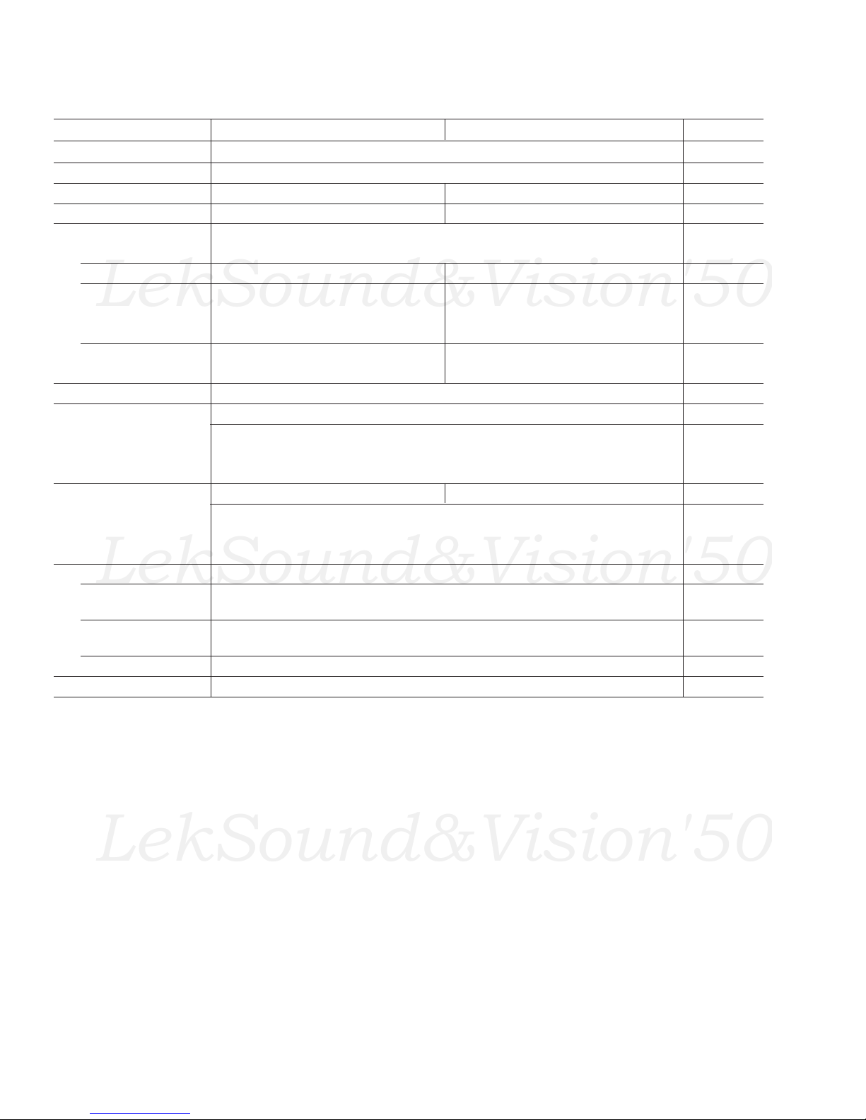
SPECIFICATIONS
LekSound&Vision'50
LekSound&Vision'50
LekSound&Vision'50
KV-2119M5J KV-J21MF2J Note
Power requirements 110-240 V AC, 50/60 Hz
Power consumption (W) Indicated on the rear of the TV
Television system B/G B/G, I, D/K, M
Color system
Channel coverage
B/G VHF: E2 to E12 / UHF: E21 to E69 / CATV: S01 to S03, S1 to S41
I – UHF: B21 to B68 / CATV : S01 to S03, S1 to S41
D/K VHF: C1 to C12, R1 to R12/
M
Audio output (speaker) 3W + 3W
Inputs ˘ (antenna): 75 ohms external terminal
Outputs A (earphone) jack: mini jack 2 (headphones) jack
Picture tube 21in.
Tube size (cm) 54
Screen size (cm) 51
Dimensions (w/h/d, mm) 610 × 470 × 474
Mass (kg) 22
PAL, P AL 60, SECAM, NTSC4.43, NTSC3.58 (AV IN)
– UHF: C13 to C57, R21 to R60/
–
… (video input) jacks: phono jacks
D (video): 1 Vp-p, 75 ohms
≥ (audio): 500 mVrms, high impedance
Ú (monitor output) jacks: phono jacks
D (video): 1 Vp-p, 75 ohms
≥ (audio): 500 mVrms
Design and specifications are subject to change without notice.
P AL, PAL 60, SECAM, NTSC4.43, NTSC3.58
CATV: Z1 to Z39, S01 to S03, S1 to S41
VHF: A2 to A13 / UHF: A14 to A79 /
CATV : A-8 to A-2, A to W+ 4, W+ 6 to W+ 84
Measured
diagonally
Measured
diagonally
CAUTION
SHORT CIRCUIT THE ANODE OF THE PICTURE TUBE AND
THE ANODE CAP TO THE METAL CHASSIS, CRT SHIELD, OR
CARBON PAINTED ON THE CRT, AFTER REMOVING THE
ANODE.
COMPONENTS IDENTIFIED BY SHADING AND MARK ! ON
THE SCHEMA TIC DIA GRAMS, EXPLODED VIEWS AND IN THE
PARTS LIST ARE CRITICAL TO SAFE OPERATION. REPLACE
THESE COMPONENTS WITH SONY PARTS WHOSE PART
NUMBERS APPEAR AS SHOWN IN THIS MANUAL OR IN
SUPPLEMENTS PUBLISHED BY SONY.
– 2 –
SAFETY-RELATED COMPONENT WARNING!!

TABLE OF CONTENTS
LekSound&Vision'50
LekSound&Vision'50
LekSound&Vision'50
Section Title Page Section Title Page
1. GENERAL....................................................................... 4
2. DISASSEMBLY
2-1. Rear Cover Removal .............................................. 8
2-2. A Board Removal ................................................... 8
2-3. Service Position ...................................................... 8
2-4. Replacement of Parts .............................................. 8
2-5. Demagnetization Coil and Picture Tube Removal. 9
3. SET-UP ADJUSTMENTS
3-1. Beam Landing ......................................................... 10
3-2. Convergence ........................................................... 11
3-3. Focus Adjustment ................................................... 13
3-4. G2 (Screen) and White Balance Adjustments........ 13
4. SELF DIAGNOSIS FUNCTION............................... 14
5. CIRCUIT ADJUSTMENTS
5-1. Adjustments with Commander ............................... 15
5-2. Adjustment Method ................................................ 16
5-3. A Board Adjustment after IC003 (Memory)
Replacement............................................................ 20
5-4. Picture Distortion Adjustment ................................ 20
6. DIAGRAMS
6-1. Block Diagrams ...................................................... 21
6-2. Circuit Boards Location ......................................... 23
6-3. Schematic Diagrams and Printed Wiring Boards... 23
(1) Schematic Diagram of A Board.............................. 29
(2) Schematic Diagrams of C and VM Boards ............ 33
6-4. Semiconductors ....................................................... 37
7. EXPLODED VIEWS
7-1. Chassis .................................................................... 39
8. ELECTRICAL PARTS LIST...................................... 40
– 3 –

3-3. FOCUS ADJUSTMENT
SERVICE
MUTING
1 F
DATA
RDR
Adjustment Item
09
Item number
WRITE1 FRDR09
0
Executes the writing
Green
LekSound&Vision'50
LekSound&Vision'50
LekSound&Vision'50
Adjust FOCUS control on the flyback transformer for the best
focus.
FOCUS
SCREEN
(NOT USED)
FLYBACK TRANSFORMER (T851)
Note: Screen VR is not used.
a. AN ITEM OF ADJUSTMENT
Item
number
09 RDR 25 WHITE POINT R
0A GDR 20 WHITE POINT G
0B BDR 20 WHITE POINT B
Adjustment
item
Initial DATA
Note
3-4. G2 (SCREEN) AND WHITE BALANCE
ADJUSTMENTS
1. G2 (SCREEN) ADJUSTMENT (RV701)
1) Set the PICTURE and BRIGHTNESS to normal.
2) Put to VIDEO input mode without signals.
3) Connect R, G, and B of the C board cathode to the oscilloscope.
4) Adjust G2 (RV701) volume to the value below.
b. METHOD OF CANCELLATION FROM SERVICE
MODE
Set the standby condition (Press [POWER] button on the
commander) and then press [POWER] button again, hereupon it
becomes TV mode.
c. METHOD OF WRITE FOR MEMORY
1) Set to Service Mode.
2) Press [1] (UP) and [4] (DOWN), select the item for adjustment.
3) Press [MUTING] button indicate WRITE (Green) on screen.
4) Press [0] button to write into memory.
d. MEMORY WRITE CONFIRMATION METHOD
1) After adjustment, pull out the plug from the AC outlet, and
then plug into the AC outlet again.
2) Turn the power switch ON and set to Service Mode.
3) Call the adjusted items again to confirm adjustments were made.
2. WHITE BALANCE ADJUSTMENTS
1) Set to Service Mode.
2) Input an entire white signal.
3) Set the PICTURE to maximum.
4) Select RDR(09) with [1] and [4] , and then set the level to 25
with [3] and [6] .
5) Select GDR(0A) and BDR(0B) with [1] and [4] and adjust the
level with [3] and [6] for the best white balance.
6) Write into the memory by pressing [MUTING] then [0] .
– 13 –
177±2 V DC
0 V
SECTION 4
LekSound&Vision'50
LekSound&Vision'50
LekSound&Vision'50
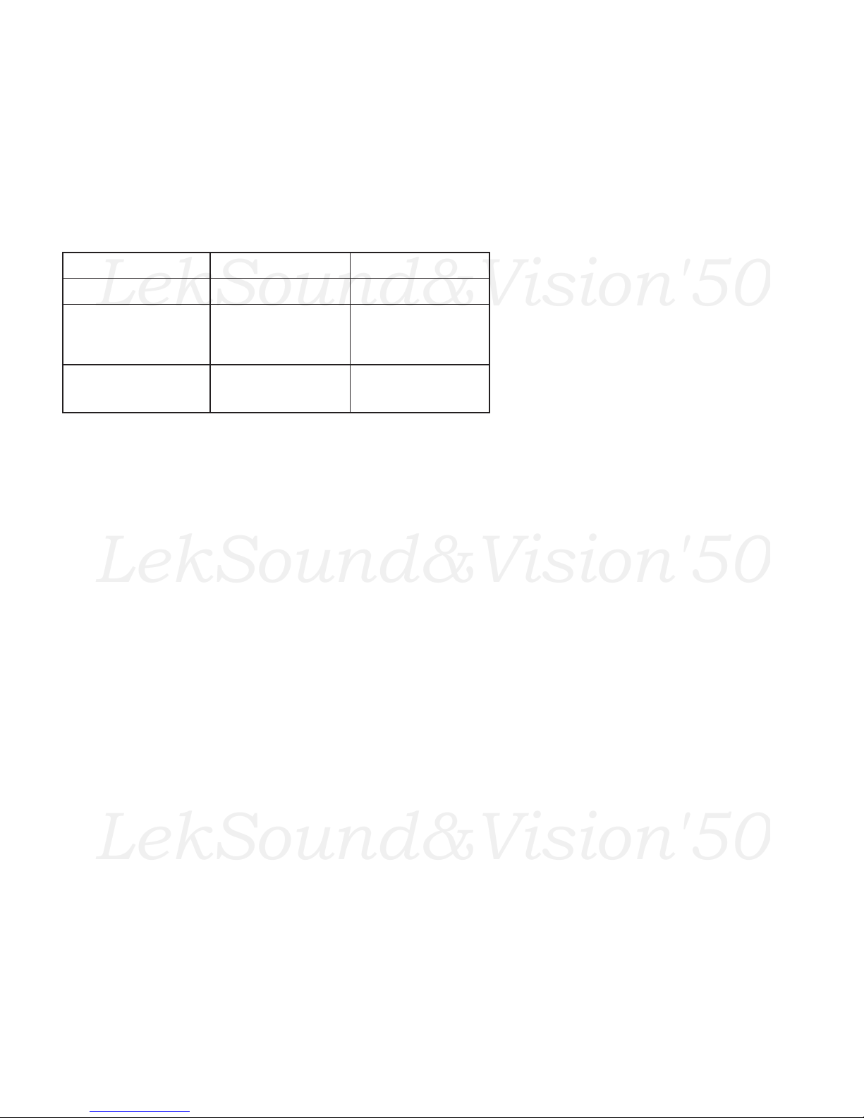
SELF DIAGNOSIS FUNCTION
If no acknowledgement is returned from a device which is turned "ON", the device has a problem.
In this case, one of the LED's responding to the problem device will flicker a defined number of times.
Flickering is operated by lighting the LED's for 60ms each time.
The flickering frequency responding to each failed device is shown below.
Board name
Ref. No.
Device
Flickering Frequency
All the devices are checked one after another from the left of the table.
If an error is found, the responding LED will start flickering.
So, if more than 1 device have failed, only the one on the left side will flicker.
A Board
IC003
NONVOLATILE
MEMORY
(ST24C04FB6)
1
A Board
IC300
Y/C JUNGLE
(TDA8375A)
3
– 14 –
 Loading...