

Sony KV-HW21P80A Schematic
REVISION HISTORY
BG2T
CHASSIS
MODEL
KV-HW21P80A
NO. SUFFIX DATE SUPP / CORR DESCRIPTION
1 -01 2003/10 _ _ 1st Issue
PA RT NO. : 9-872-406-01
SERVICE MANUAL
BG2T
CHASSIS
MODEL COMMANDER DEST. CHASSIS NO.
KV-HW21P80A RM-969 Pakistan
(Silver)
RM 969
(Light Blue)
MODEL COMMANDER DEST. CHASSIS NO.
3
1
2
6
4
5
9
7
8
JUMP
-
0
SOUND
PROGR
2
MODE
SPACE
SOUND
TV
TRINITRON
3
1
2
6
4
5
9
7
8
JUMP
-
0
SOUND
PROGR
2
MODE
SPACE
SOUND
TV
®
COLOR TV

KV-HW21P80A
RM-969
TABLE OF CONTENTS
Section Title Page
SELF DIAGNOSIS FUNCTION...................................... 3
1. DISASSEMBLY
1-1. Rear Cover Removal ................................................. 6
1-2. Speaker Removal ...................................................... 6
1-3. Chassis Assy Removal .............................................. 6
1-4. Service Position ........................................................ 6
1-5. Terminal Bracket Removal ....................................... 6
1-6. A Board Removal...................................................... 6
1-7. Picture Tube Removal ............................................... 7
2. SET-UP ADJUSTMENTS
2-1. Beam Landing ........................................................... 8
2-2. Convergence .............................................................. 9
2-3. Focus Adjustment.................................................... 11
2-4. G2 (SCREEN) and White Balance Adjustments ... 11
3. CIRCUIT ADJUSTMENTS
3-1. Adjustment With Commander ................................ 12
3-2. Adjustment Method ................................................ 12
3-3. Picture Quality Adjustment .................................... 18
3-4. Deflection Adjustment ............................................ 18
3-5. A Board Adjustment After IC003 (MEMORY)
Replacement ............................................................ 18
3-6. Picture Distortion Adjustment ................................ 19
Section Title Page
4. DIAGRAMS
4-1. Block Diagram ........................................................ 20
4-2. Circuit Boards Location .......................................... 22
4-3. Schematic Diagram ................................................. 22
(1) A Board Schematic Diagram ............................ 23
(2) C Board Schematic Diagrams ........................... 25
4-4. Voltage Measurement and Wareforme ................... 26
4-5. Printed Wiring Boards and Parts Location ............. 29
4-6. Semiconductors ....................................................... 32
5. EXPLODED VIEWS
5-1. Picture Tube and Chassis ........................................ 34
6. ELECTRICAL PARTS LIST .................................... 35
OPERATING INSTRUCTIONS
CAUTION
SHORT CIRCUIT THE ANODE OF THE PICTURE TUBE AND
THE ANODE CAP TO THE METAL CHASSIS, CRT SHIELD,
OR CARBON PAINTED ON THE CRT, AFTER REMOVING THE
ANODE.
SAFETY-RELATED COMPONENT WARNING!!
COMPONENTS IDENTIFIED BY SHADING AND MARK ! ON
THE SCHEMATIC DIAGRAMS, EXPLODED VIEWS AND IN
THE PARTS LIST ARE CRITICAL TO SAFE OPERATION.
REPLACE THESE COMPONENTS WITH SONY PARTS
WHOSE PART NUMBERS APPEAR AS SHOWN IN THIS
MANUAL OR IN SUPPLEMENTS PUBLISHED BY SONY.
– 2 –

KV-HW21P80A
SELF DIAGNOSIS FUNCTION
The units in this manual contain a self-diagnosis function. If an error occurs, the STANDBY (1) indicator will automatically begin to flash. A description of the self-diagnosis function is explained in the instruction manual.
The number of times the STANDBY (1) indicator flashes translates to a probable source of the problem. If an error
symptom cannot be reproduced, the remote commander can be used to review the failure occurrence data stored in
memory to reveal past problems and how often these problems occur.
1. DIAGNOSIS TEST INDICATORS
When an errors occurs, the STANDBY (1) indicator will flash a set number of times to indicate the possible cause of the
problem. If there is more than one error, the indicator will identify the first of the problem areas.
Result for all of the following diagnosis items are displayed on screen. No error has occured if the screen displays a “0”.
RM-969
Diagnosis
Item
Description
• Power does not
turn on
• +B overcurrent
(OCP)
• Horizontal
deflection
overdrive
• White balance
failure (no
PICTURE)
• Vertical deflection
stopped
• Micro reset
No. of times
STANDBY (1)
indicator flashes
Does not light
2 times
4 times
—
Self-diagnostic
display/Diagnosis
result
—
002:000 or
002:001~255
004:000 or
004:001~225
101:00 or
101:001~225
Probable
Cause
Location
• Power cord is not
plugged in.
• Fuse is burned out
F600 (F)
• H.OUT Q801 is shorted.
(A board)
• -13V is not supplied.
(A board)
• IC 551 faulty (A board)
• Discharge CRT
(C Board)
• Static discharge
• External noise
Detected
Symptoms
• Power does not turn on.
• No power is supplied to
the TV.
• AC power supply is faulty.
• Power does not turn on.
• Load on power line is
shorted.
• Has entered standby state
after horizontal raster.
• Power line is shorted or
power supply is stopped.
• Vertical deflection pulse
is stopped
• Power is shut down
shortly, after this return
back to normal.
• Detect Micro latch up.
Note 1: If a + B overcurrent is detected, stoppage of the vertical deflection is detected simultaneously.
The symptom that is diagnosed first by the microcontroller is displayed on the screen.
Note 2: Refer to screen (G2) Adjustment in section 3-4 of this manual.
– 3 –
KV-HW21P80A
RM-969
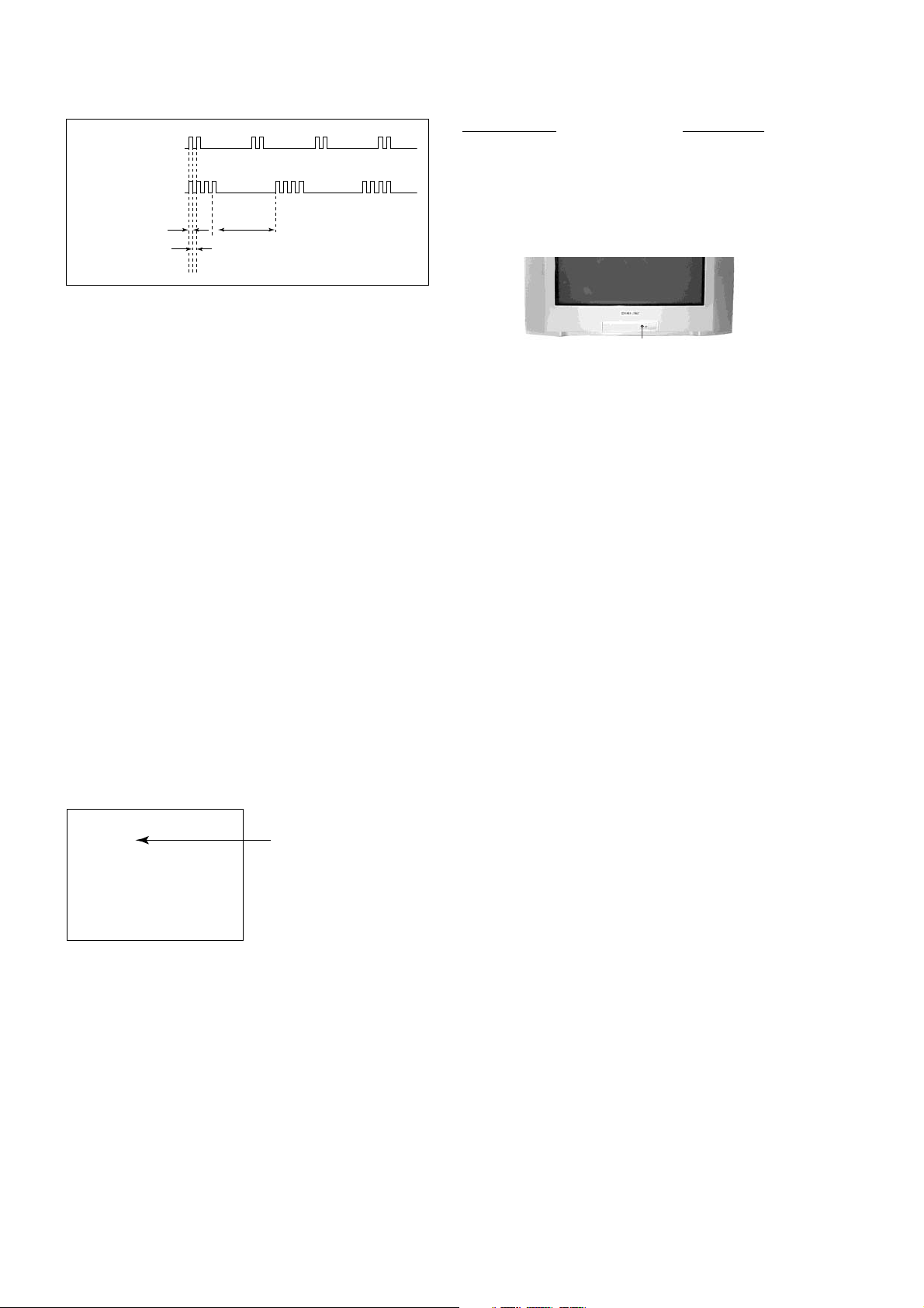
2. DISPLAY OF STANDBY (1) INDICATOR FLASH COUNT
2 times
Diagnosis Item Flash Count*
+B overcurrent/overvoltage 2 times
4 times
Lamp ON 0.3 sec.
Lamp OFF 0.3 sec.
Lamp OFF 3 sec.
Vertical deflection stopped 4 times
* One flash count is not used for self-diagnosis.
STANDBY (1) indicator
3. STOPPING THE STANDBY (1) INDICATOR FLASH
Turn off the power switch on the TV main unit or unplug the power cord from the outlet to stop the STANDBY (1)
indicator from flashing.
4. SELF-DIAGNOSTIC SCREEN DISPLAY
For errors with symptoms such as “power sometimes shuts off” or “screen sometimes goes out” that cannot be confirmed, it is possible to bring up past occurances of failure for confirmation on the screen:
[To Bring Up Screen Test]
In standby mode, press buttons on the remote commander sequentially in rapid succession as shown below:
[Screen display] / channel [5] / Sound volume [-] / Power ON
˘
Note that this differs from entering the service mode (volume [+]).
Self-Diagnostic screen display
SELF DIAGNOSTIC
002 : 000
004 : 000
101 : 000
Numeral "0" means that no fault has been detected.
– 4 –
KV-HW21P80A
5. HANDLING OF SELF-DIAGNOSTIC SCREEN DISPLAY
Since the diagnosis results displayed on the screen are not automatically cleared, always check the self-diagnostic
screen during repairs. When you have completed the repairs, clear the result display to “0”.
Unless the result display is cleared to “0”, the self-diagnosis function will not be able to detect subsequent faults after
completion of the repairs.
[Clearing the result display]
To clear the result display to “0”, press buttons on the remote commander sequentially as shown below when the selfdiagnostic screen is being displayed.
Channel [8] / 0
[Quitting Self-diagnostic screen]
To quit the entire self-diagnostic screen, turn off the power switch on the remote commander or the main unit.
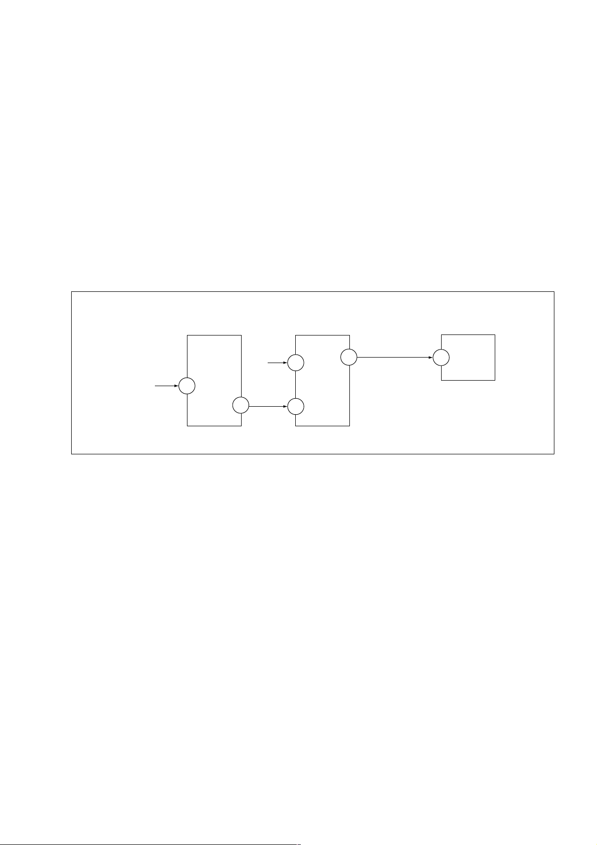
6. SELF-DIAGNOSIS CIRCUIT
RM-969
FROM
[+B] Q500
IC301
Y/CHROMA JUNGLE
MP/
50
PROTECT
8
SDA
[V]
D553
IC001
SYSTEM
11 DAT1 DAT
17
54
11 DAT0
53
IC003
MEMORY
5
[+B overcurrent $OCP%] Occurs when an overcurrent on the +B(135) line is detected by Q500. If Q500 go to
ON and the voltage to pin 50 of IC301 more than 3.5V when V.SYNC is more than
seven verticals in a period, the unit will automatically turn off.
[Vertical deflection stopped] Occurs when an absence of the vertical deflection pulse is detected by Pin 17 and
IC001 shut down the power supply.
[White balance failure] If the RGB levels* do not balance or become low level within 5 seconds, this error
will be detected by IC301. TV will stay on, but there will be no picture.
* (Refers to the RGB levels of the AKB detection Ref pulse that detects IK.)
– 5 –
KV-HW21P80A
RM-969
SECTION 1
DISASSEMBLY
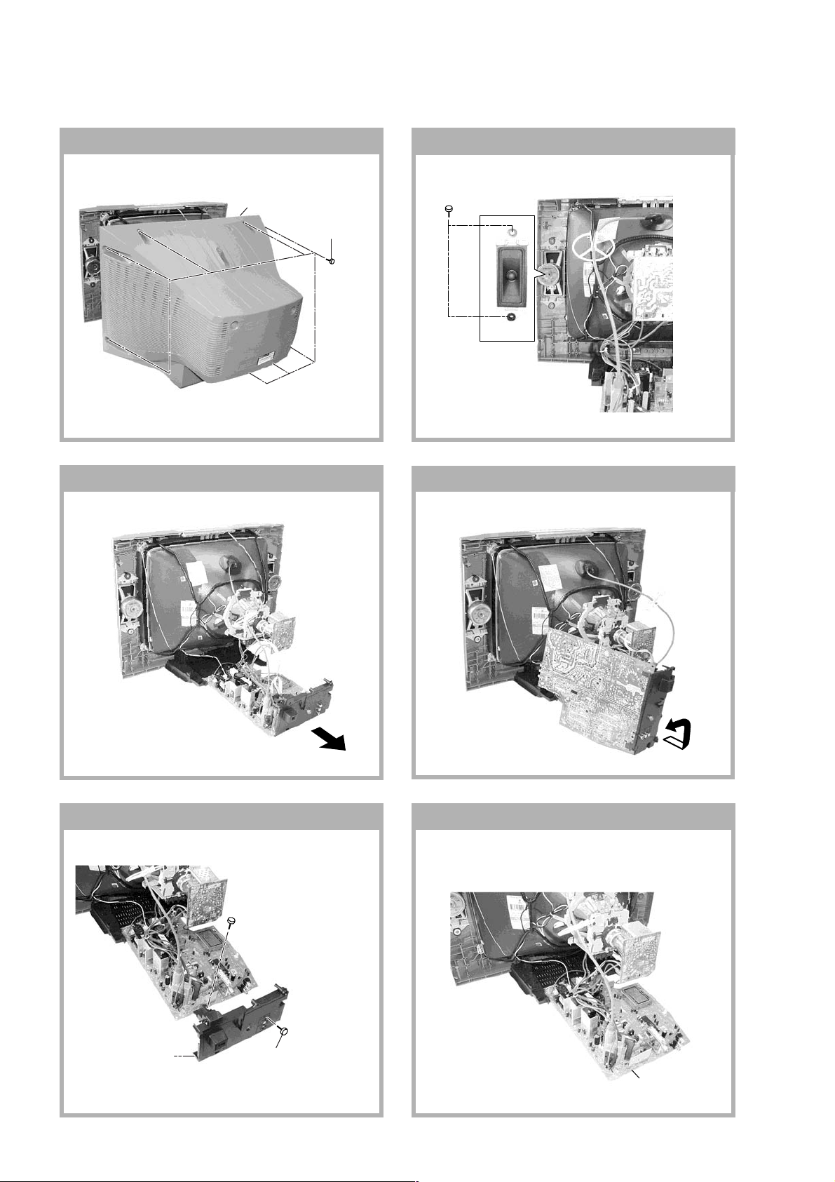
1-1. REAR COVER REMOVAL
2 Rear cover
1-3. CHASSIS ASSY REMOVAL
1Eight screws
(BVTP 4 × 16)
1-2. SPEAKER REMOVAL
1 Two screw
(+BVTP 4 × 16)
1-4. SERVICE POSITION
1-5. TERMINAL BRACKET REMOVAL 1-6. A BOARD REMOVAL
2 One screw
(+BVTP 3 × 16)
1 Terminal
bracket
3 Two screw
(+BVTP 4 × 16)
– 6 –
A board
KV-HW21P80A
c
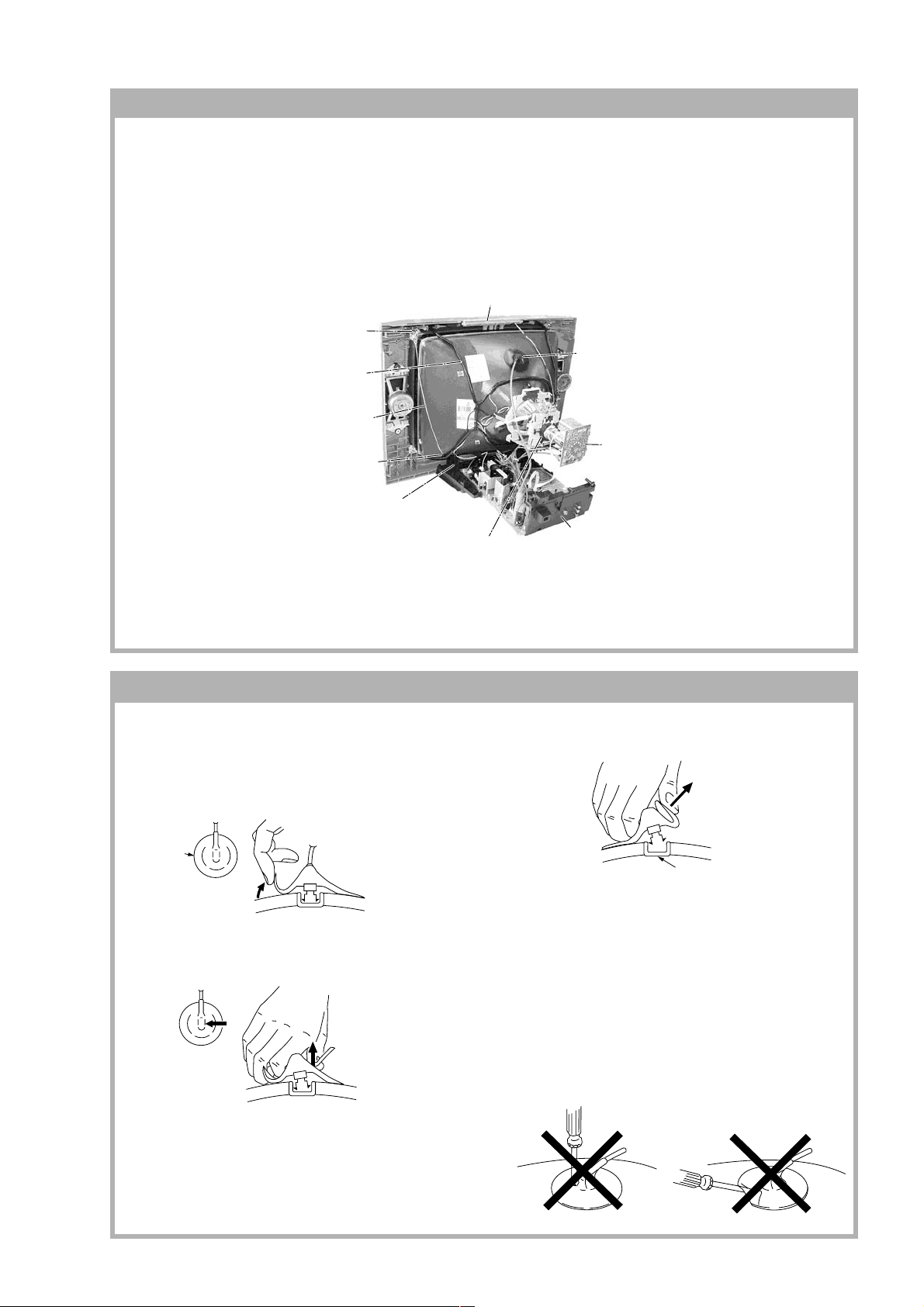
1-7. PICTURE TUBE REMOVAL
Note:
• The picture tube is upside-down and the position for the anode cap and tension springs are changed accordingly.
• Please make sure the TV set is not in standing position before removing necessary CRT support located on bottom
right and left.
1) Place the TV set with the CRT face down on a cushion jig.
2) Remove the rear cover.
3) Unplug all inder connecting leads from the Deflection Yoke, Degaussing Coil and CRT grounding strap.
qd Top Switch Block
qs Nut, Special, CRT (4)
4 Anode Cap Removal
qa Degaussing Coil
0 Earth Coating Assy
5 C Board Removal
9 Spring Tension Removal
RM-969
8 Support, CRT(2) Removal
7 Loosen the Deflection Yoke
fixing screw and remove
6 Chassis Assy Removal
• REMOVAL OF ANODE-CAP
Note:
• After removing the anode, short circuit the anode of the picture tube and the anode cap to the metal chassis, CRT
shield or carbon paint on the CRT.
• REMOVING PROCEDURES
a
a
1 Turn up one side of the rubber cap in the direction
indicated by the arrow A.
b
b
turning up the rubber cap and pulling it up in the
direction of the arrow C.
• HOW TO HANDLE AN ANODE-CAP
1 Do not damage the surface of anode-caps with
sharp shaped objects.
2 Do not press the rubber too hard so as not to
damage the inside of anode-cap.
A metal fitting called the shatter-hook terminal is
built into the rubber.
3 Do not turn the foot of rubber over too hard.
The shatter-hook terminal will stick out or damage
the rubber.
anode button
2 Using a thumb pull up the rubber cap firmly in the di-
rection indicated by the arrow B.
3 When one side of the rubber cap is separated from
the anode button, the anode-cap can be removed by
– 7 –
KV-HW21P80A
RM-969
SECTION 2
SET-UP ADJUSTMENTS
The following adjustments should be made when a complete
realignment is required or a new picture tube is installed.
These adjustments should be performed with rated power
supply voltage unless otherwise noted.
Controls and switches should be set as follows unless otherwise
noted:
PICTURE control ........................................................... normal
BRIGHTNESS control................................................... normal
................................................................................................................................................................................................................................
Preparation :
In order to reduce the influence of geomagnetism on the
set's picture tube, face it east or west.
Switch on the set's power and degauss with the degausser.
Perform the adjustments in the following order :
1. Beam Landing
2. Convergence
3. Focus
4. White Balance
Note : Test Equipment Required.
1. Pattern Generator
2. Degausser
3. Oscilloscope
Purity control
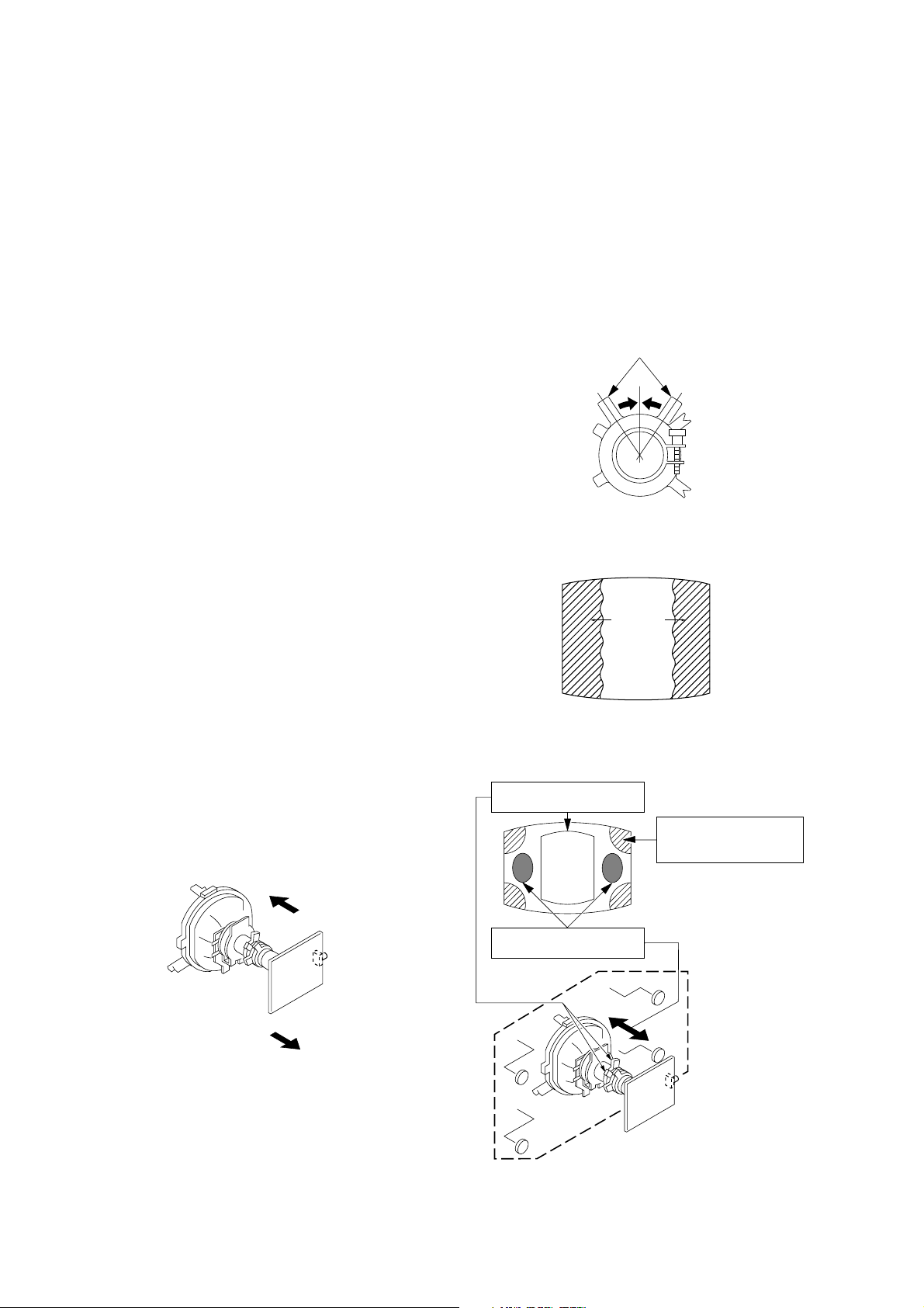
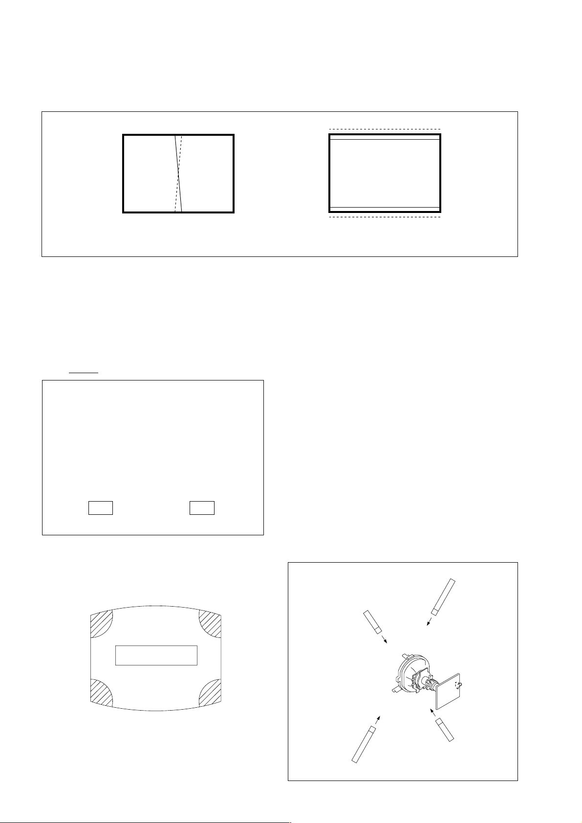
2-1. BEAM LANDING
1. Input a white signal with the pattern generator.
Contrast
Brightness
2. Set the pattern generator raster signal to a green raster.
3. Move the deflection yoke to the rear and adjust with the
purity control so that the green is at the center and the blue
and the red take up equally sized areas on each side.
(See Figures 2-1 through 2-4.)
4. Move the deflection yoke forward and adjust so that the
entire screen is green. (See Figure 2-1.)
5. Switch the raster signal to blue, then to red and verify the
condition.
6. When the position of the deflection yoke has been decided,
fasten the deflection yoke with the screws and DY spacers.
7. If the beam does not land correctly in all the corners, use a
magnet to adjust it.
(See Figure 2-4.)
}
normal
Fig. 2-2
Red
Green
Fig. 2-3
Purity control corrects
this area.
ba
Blue
Disk magnets or rotatable
disk magnets correct
these areas (a-d).
Fig. 2-1
– 8 –
c
Deflection yoke positioning
corrects these areas.
a
d
d
Fig. 2-4
b
c
KV-HW21P80A
R
R
G
G
B
B
a
a
b
b b
RM-969
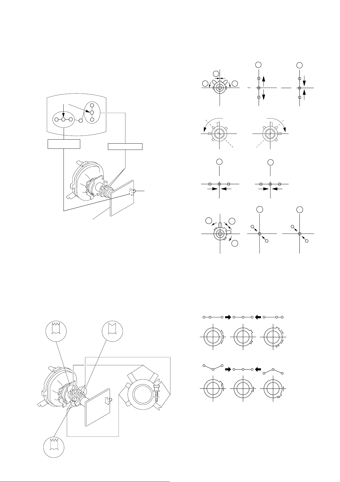
2-2. CONVERGENCE
Preparation :
• Before starting this adjustment, adjust the focus, horizontal
size and vertical size.
• Receive dot/hatch signal.
• Pic mode: Soft.
(1) Horizontal and Vertical Static Convergence
Center dot
R G B
H. STAT VR
R
G
B
V.STAT Magnet
RV 702
• Operation of V. Stat magnet
If the V. Stat magnet is moved in the "a" and "b" arrows, the
red, green and blue dots move as shown below.
1
2
a
a
RGGBB
b
b
R
C board
1. (Moving vertically), adjust the V.STAT magnet so that the
red, green and blue dots are on top of each other at the
center of the screen.
2. (Moving horizontally), adjust the H.STAT VR control so
that the red, green and blue dots are on top of each other at
the center of the screen.
3. If the H.STAT variable resistor cannot bring the red, green
and blue dots together at the center of the screen, adjust the
horizontal convergence with the H.STAT variable resistor
and the V.STAT magnet in the manner given below.
(In this case, the H.STAT variable resistor and the V.STAT
magnet influence each other, so be sure to perform
adjustments while tracking.)
BMCPurity
BMC (Hexapole)
Purity
3
b
a
a
R
B
G
b
B
4 BMC (Hexapole) Magnet.
If the red, green and blue dots are not balanced or aligned,
then use the BMC magnet to adjust in the manner described
below.
RG B R G B R GB
RB
G
RG
GB
RB
b
G
R
V.STAT
V.STAT
– 9 –
KV-HW21P80A
RM-969
(2) Dynamic Convergence Adjustment
Preparation:
Before starting this adjustment, adjust the horizontal static
convergence and the vertical static convergence
RB
TLH Insert TLH Correction Plate to DY Pocket (Left or
Right)
YCH Rotate YCH VOL on DY
TLV Rotate TLV VOL ON DY
XCV Rotate XCV Adj core on DY
ON DY:
B
R
TLVYCH
YCH TLV
(3) Screen-corner Convergence
ba
a-d : screen-corner
misconvergence
cd
– 10 –
Fix a Permalloy assy
corresponding to the
misconverged areas
a
d
b
c
a to d : Permalloy assembly
KV-HW21P80A
RM-969
2-3. FOCUS ADJUSTMENT
FOCUS adjustment should be completed before W/B adjustment.
1. Receive digital monoscope pattern.
2. Set "Picture Mode" to "DYNAMIC".
3. Adjust focus VR so that the center of screen becomes
just focus.
4. Change the receiving signal to white pattern and blue back.
5. Confirm magenta ring is not noticeable. Incase magenta is
very obvious, adjust focus VR to take balance of magenta
ring and focus.
FOCUS
SCREEN
2.a) WHITE BALANCE ADJUSTMENT
1) Set to Service Mode (Refer Section 3-1: ADJUSTMENTS
WITH COMMANDER).
2) Input white raster signal.
3) Set 49 (ABL) and IF (VP2) service mode to 00.
4) Set Picture to DYNAMIC.
5) Select OB (RDR) with [1] and [4], and set the level to 25
with [3] and [6] for best white balance.
6) Select OC 'GDR' and OD 'BDR' with [1] and [4], and adjust
the level with [3] and [6] for the best white balance.
7) Write into the memory by pressing [MUTING] then [0].
8) Set back 49 'ABL' and IF 'VP2' service mode to original data.
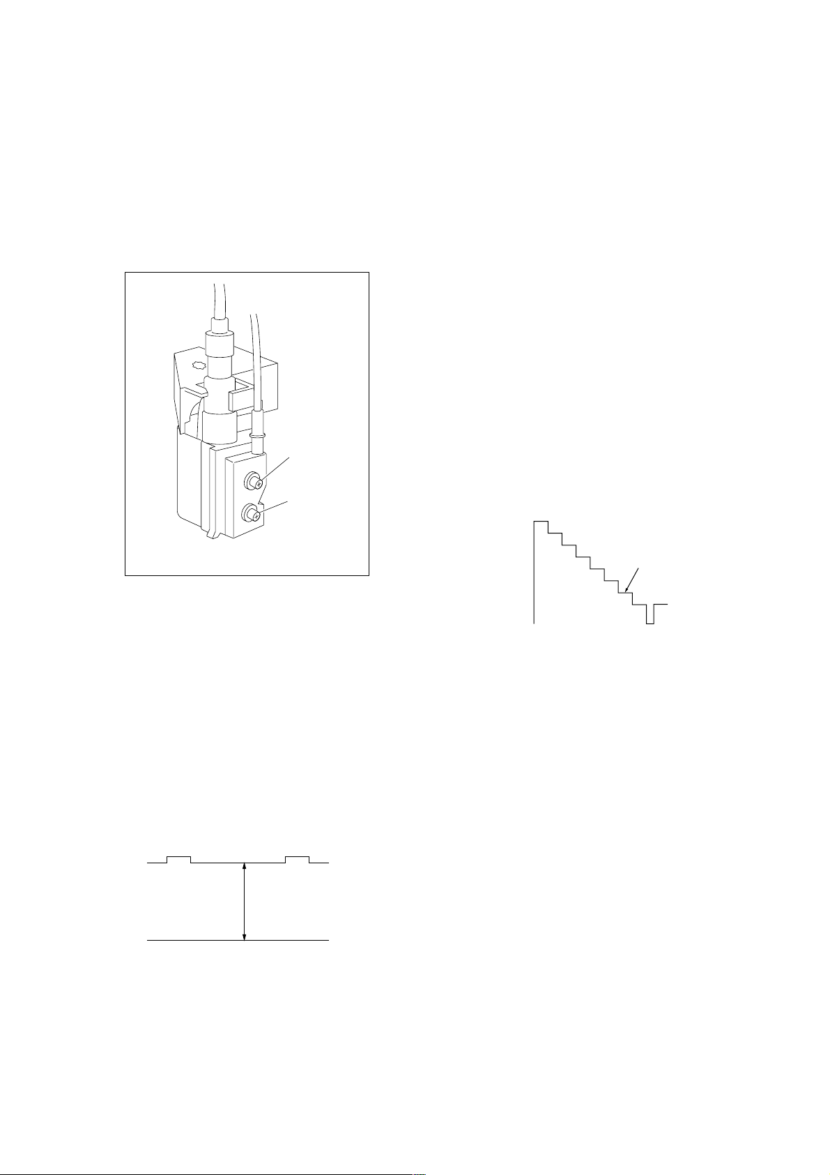
2.b) SUB BRIGHT ADJUSTMENT
1) Set to service mode.
2) Set 49(ABL) and IF (VP2) service mode to 00
3) Input a staircase signal of black to white from the pattern
generator.
4) BRIGHTNESS ....50%.
PICTURE ............MINIMUM
5) Select OE 'SBR' with [1] and [4], and adjust OE 'SBR' level
with [3] and [6] so that the second stripe from the right is
dimly lit.
6) Write into the memory by pressing [MUTING] then [0].
7) Set back 49 (ABL) and IF (VP2) service mode to original data.
FLYBACK TRANSFORMER (T503)
2-4. G2 (SCREEN) AND WHITE BALANCE
ADJUSTMENTS
1. G2 (SCREEN) ADJUSTMENT
1) Set the PICTURE to normal.
2) Put to VIDEO input mode without signals.
3) Connect R, G and B of the C board cathode to the
oscilloscope.
4) Adjust BRIGHTNESS to obtain the cathode voltage to the
value below.
5) Adjust G2 (screen) on the FBT until picture shows the point
before cut off.
Cathode setting voltage:
175 V ± 2 (VDC)
White
second from the right
Black
0 V
– 11 –
KV-HW21P80A
RM-969
SECTION 3
CIRCUIT ADJUSTMENTS
3-1. ADJUSTMENT WITH COMMANDER
Service adjustments to this model can be performed using the
supplied Remote Commander RM-969.
a. ENTERING SERVICE MODE
With the unit on standby
n
[DISPLAY] n [5] n [VOL$+%] n [POWER]
This operation sequence puts the unit into service mode.
The screen display is :
Item
Adjustment
Mode
Item No
HPS 33 SERVICE
00
080S
Suffix No
(OEM Code)
b. METHOD OF CANCELLATION FROM SERVICE
MODE
Set the standby condition (Press [POWER] button on the commander), then press [POWER] button again, hereupon it becomes
TV mode.
1.6C
Software version
Data
00 000A
Total Power-On time (hours)
Depends on signal
50
PAL,SECAM:50
NTSC :60
e. OTHER FUNCTION VIA REMOTE COMMANDER
[7], [0] All the data becomes the values in memory.
[8], [0] All user control goes to the standard state.
[5], [0] Service data initialization (Be sure not to use
usually.)
[2], [0] Copy and write all data.
[MUTE], [0] Write 50Hz adjustment data to 60Hz or vice
versa.
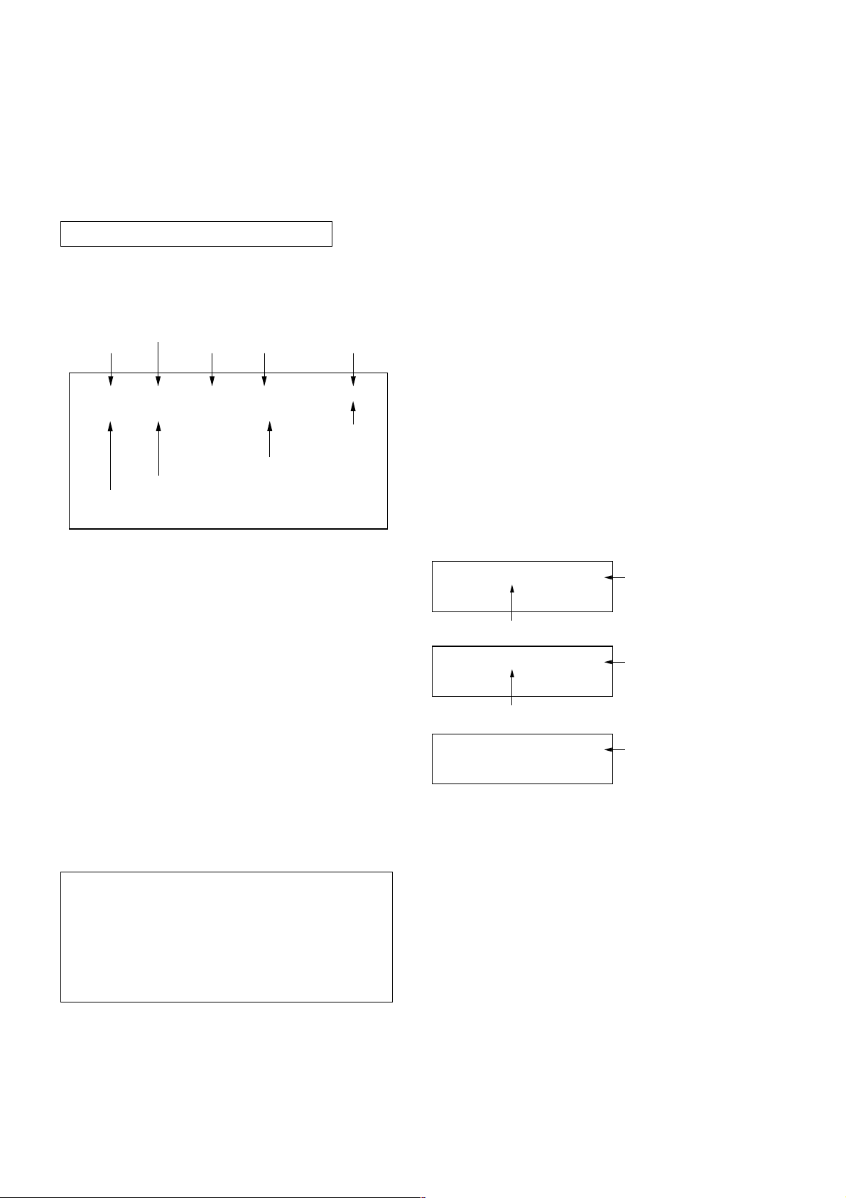
3-2. ADJUSTMENT METHOD
Item Number 00 HPS
This explanation uses H Shift as an example.
1. Select “00 HPS” with the
2. Raise/lower the data with the [3] and [6] buttons.
3. Select the optimum state. (The standard is 1F for PAL
reception.)
4. Write with the
WRITE.)
5. Execute the writing with the
display will be changed to red color while excuting, and
back to SERVICE.)
Example on screen display :-
00
Adjusted with [3] and [6] buttons.
[MUTING] button. (The display changes to
33 SERVICE 50HPS
[1] and [4] buttons.
[0] button. (The WRITE
GREEN
c. METHOD OF WRITE INTO MEMORY
1) Set to Service Mode.
2) Press
4) Press [MUTING] button to indicate WRITE on the screen.
5) Press [0] button to write into memory.
d. MEMORY WRITE CONFIRMATION METHOD
1) After adjustment, pull out the plug from AC outlet, and then
2) Turn the power switch ON and set to Service Mode.
3) Call the adjusted items again to confirm adjustments were
[1] (UP) and [4] (DOWN), to select the adjustment.
plug into AC outlet again.
made.
[1], [4] Select the adjustment item.
↓
[3], [6] Raise/lower the data value.
↓
[MUTING] Writes.
↓
[0] Executes the writing.
00
00
Write executed with [0]
Use the same method for all Items. Use 1 and 4 to select the
adjustment item, use 3 and 6 to adjust, write with [MUTING],
then execute the write with -.
Note : 1. In [WRITE], the data for all items are written into
2. For adjustment items that have different standard
33 WRITE 50HPS
Write with [MUTING]
33 WRITE 50HPS
memory together.
data between 50Hz or 60Hz, be sure to use the
respective input signal after adjustment.
GREEN
The WRITE display
then returns to
SERVICE
– 12 –
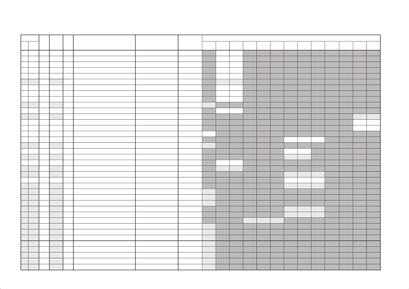
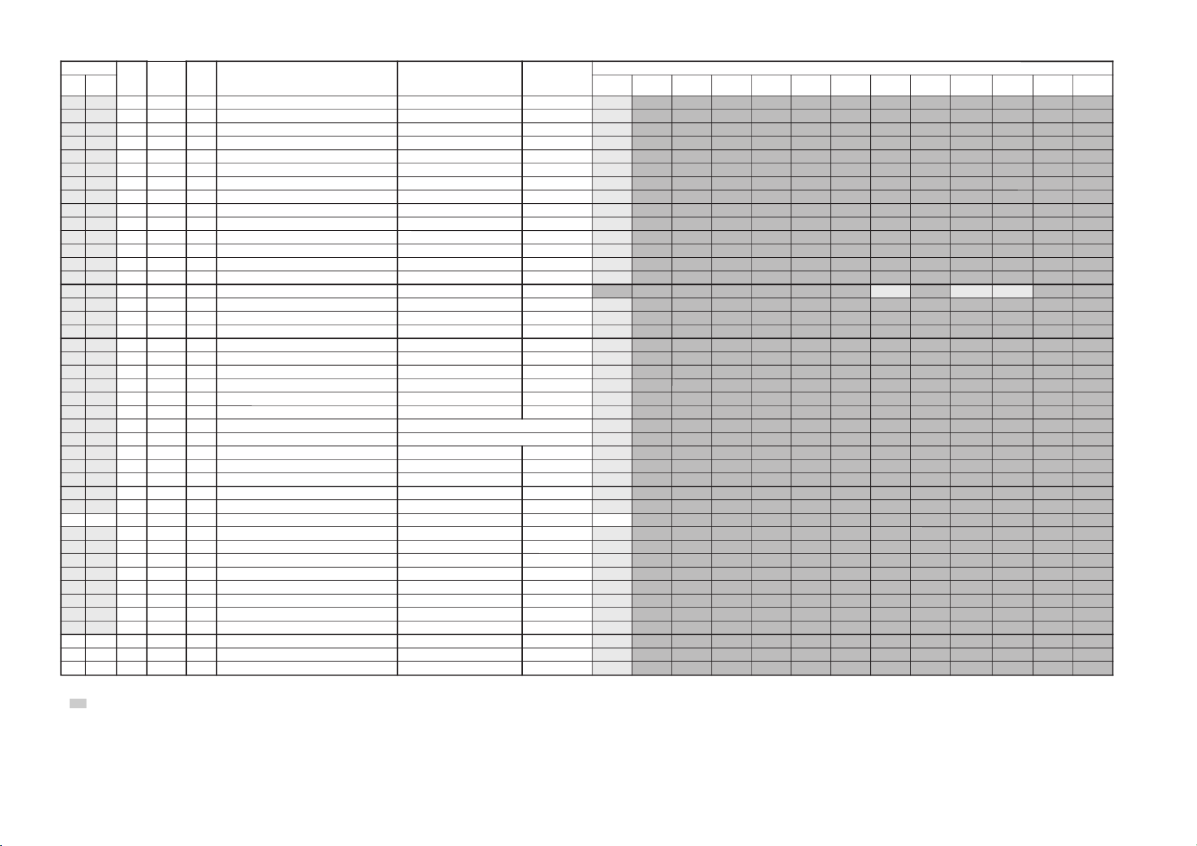
Adjustment Item Table
ytilanoitcnuF.tinIecivreS
atad
egnaRnoitcnuFetoN&elbaTemaNeciveD
)sserddAevalS(
.oNemaN nommoC0506MACESCSTNLAPVToediVtxeteleTmetsySMM-noN
metsyS
cimanyDsrehtO
00SPHA242F3noitisoPHzH06/05)A8(44/3488ADT
A2A2
10ZSHF132F3eziSHzH06/05
F1F1
20PAPF112F3edutilpmAniPzH06/05
F1F1
30NPCF192F3niPrenroCzH06/05
F1F1
40TLTF102F3tliTzH06/05
F1F1
50
LSV62
02F3epolSVzH06/05
02
02
60PAVF0D1F3edutilpmAVzH06/05
F0F0
70OCSF002F3noitcerroCSzH06/05
F0F0
80SPVF102F3tfihSVzH06/05
F1F1
90
MZV91
91F3mooZlacitreV
91
A0CSVF1F1F3llorcSlacitreVzH06/05
F1F1
B0
RDRF1
42/F1F3evirDR srehtO/cimanyD
#
#
C0RDG5252F3evirDG srehtO/cimanyD
5252
D0RDB5252F3evirDB srehtO/cimanyD
5202
E0RBS85B4F7ssenthgirBbuS 85
F0XMP0272F3ataDmumixaMerutciP txeteleT/oediV/VT
020202
01
IMP40
40F3ataDmuminiMerutciP
40
11UHS7050F0euHbuSoediV/VT
7090
21
HSS10
30/1030ssenprahSbuSoediV/VT
# #
311CS02F1F3rewoLroloCbuSzH06/05
02C1
41
2CS80
#F3rehgiHroloCbuSzH06/05
#
#
51
OF00
0030tnatsnoCemiT10 txeteleT/oediV/VT
00
00
00
61TGA000F3revOekaTCGA txeteleT/oediV/VT
000000
71
WSV00
0/1/010hctiwSetuMoediV txeteleT/oediV/VT
00 10
00
81
ROF30
3030ycneuqerFdleiFdecroF
30
91
LD00
010ecalretni-eD
00
A1
COP00
010edoM.orhcnyS10dexiF
00
B1
ROC10
0/0/110gniroCesioN txeteleT/oediV/VT
10
00
00
C1
LBR00
010gniknalBBGR txeteleT/oediV/VT
00
00 00
D1
LDYA0
A0/C0/60F0yaleD-Y MACES/CSTN/LAP
A0
C0
60
E1
1PV00
#FF)segapdeificepsees(stiBartxE
#
F1
2PV10
10FF)segapdeificepsees(stiBartxE
10
02
3PVF0
#FF)segapdeificepsees(stiBartxE
#
12
TSW51
51FFdlohserhToeretSG/W )08(G7143PSM
51
22
TBWCE
CBFFdlohserhTlaugniliBG/W
CE
32
LLW50
50FFdlohserhTlaruanoMG/W
50
42
CAW10
10F0tnuoCtnemeergAG/W
10
52
LDW03
03FFyaleDhcraeSG/W
03
– 13 –
KV-HW21P80A
RM-969
Adjustment Item Table
ytilanoitcnuF.tinIecivreS
atad
egnaRnoitcnuFetoN&elbaTemaNeciveD
)sserddAevalS(
atademaN nommoC0506MACESCSTNLAPVToediVtxeteleTmetsySMM-noN
metsyS
cimanyDsrehtO
62
LDN0202FFyaleDhcraeSMACIN
02
72
LDS0101FFyaleDdaeRsutatSoeretS
01
82
CGA101010tnatsnoc/otuahctiwSCGA
10
92
LER8282F3edoMtnatsnoCtaniaGCGA
82
A2
MRC00010ffo/nognituMreirraC
00
B2
OCA10110ffo/notuo-kcolCoiduA
10
C2
PFB1B1F7K/D,I,G/BrofelacserPMF
B1
D2
MPF2323F7MrofelacserPMF
23
E2
HF6363F7)M-non(VEDHrofelacserPMF
63
F2
MHF5656F7)M(VEDHrofelacserPMF
56
03
PGWC1C1F7elacserPG/W
C1
13
PINF7F7F7elacserPMACIN
F7
23
RRE0505FFdlohserhThctiwSMFotuA
05
33
LOVD6#F7mumixaMemuloVPFD
#
43
GNI00#F0niaGtupnI oediV/M-non/metsySM)88(8347ADT
#
#
#
53
MOV00#F3niaGtuptuOemuloV ylnometsySM
#
63
SCB10#30tfihSretneCssaB
#
73
SCT20#30tfihSretneCelberT
#
83
HXTA2A2FFnoitisoPyalpsiDlatnoziroH )85(4625AAS
A2
93
VXT7272F3)cnys-Vmorftesffoenil(noitisoPyalpsiDlacitreV
72
A3
DHT0000F7tfihSegdEevitcAcnys-H
00
B3
DVTF3F3F7tfihSegdEevitcAcnys-V
F3
C3
LPH101010noitarugifnoCytiraloPcnys-H evitageN:10,evitisoP:00
10
D3
LPV101010noitarugifnoCytiraloPcnys-V evitageN:10,evitisoP:00
10
E3
LPF101010noitarugifnoCytiraloPdleiF enilflahtsrifcnys-V:10,enilflahdnocescnys-V:00
10
F3
DMF000000edoMecroF edoMpoT:30,txetsaF:20,tluafeD:10,otuA:00
00
04
RBT8080F0ssenthgirBBGRtxeteleTteS
80
14
PON1010F0noitarugifnoCelbaTnoitpOlanoitaN
10
24
HCT101030noitarugifnoCteSretcarahCdetsiwT
10
34
PKB0000F3FFOgniknalBtaataDerutciP lortnoCrehtO
00
44
LDO01#FFyaleDNOrewoP
#
54HSOA0A0F3noitisoPHDSO A0
64
YST000030teserPotuAtametsySVT M:30,K/D:20,I:10,G/B:00
00
74
SKD101010elbasid/elbaneoeretSK/D
10
84
TUM000010cnySoNtaffo/nognituM
00
94
LBA101010hctiwSLBAthgirB
10
A4
MCS101010evitcani/evitcaparTMACES
10
B4
SLS101010cnySIFI.RO.LSetavitcA
10
C4
VSS202070pUpetSemuloVdnuoSecapS
20
D4
WPV5353F7tiawputratsrossecorPoediVforemiT
53
E41POF2#FF)segapdeificepsees(0sgalFlanoitpO
#
F42POF0#FF)segapdeificepsees(1sgalFlanoitpO
#
053PO00#FF)segapdeificepsees(2sgalFlanoitpO
#
KV-HW21P80A
RM-969
– 14 –
NOTE:
•
Bold item :- are fixed data
•
Standard data listed on the Adjustment Item Table are reference values, therefore it may be different for each model and for each mode.
•
Note for Different Data Those are the standard data values written on the microprocessor. Therefore, the data values of the modes and stored respectively in the memory.
In case of a device replacement, adjustment by rewriting the data value is necessary for some items.
ITEM INFORMATION
No. 1E VP1
Item
KV-HW21P80A
BCO Switch-on behaviour 1=Switch -on of picture via internal delay 0=Without delay 00(4)
OSO 1=Switch off in vertical overscan 0=Switch-off undefind 18(7)
SBL Service blanking 1= on 0= off 0B(7)
HBL RGB Blanking Mode 1 = wide blanking, 0 = normal blanking 02(7)
FCO Forced Color-on 1=no colour killer 0=normal colour killer function 1B(0)
FFI Fast filler IF-PLL 1=increased time constant 0=normal time constant 1A(1)
No. 1F VP2
KV-HW21P80A
RM-969
-
0
-
0
BCO
0
OSO
0
SBL
0
HBL
0
FCO
0
FFI
0
Item
KV-HW21P80A
MAT PAL-SECAM-/NTSC Matrix 1 =PAL matrix, 0=adapted to standard 0E(7)
DS Dynamic skin control on/off 1= on 0= off 1A(3)
DSA Dynamic skin control angle 1=correction angle 117 degrees 0=correction angle 123 degrees 1A(2)
EBS Extended Blue Stretch 1= on 0= off 1A(0)
BLS Blue stretch 1= on 0= off 18(4)
BKS Black stretch 1= on 0= off 18(3)
No. 20 VP3
Item
KV-HW21P80A
BB Blue back when no video signal is identified 1= on 0= off 18(0)
AKB Black current stabilisation 1=not active 0=active 02(6)
BPS Bypass of chroma base-band delay line 1=bypassed 0=active 19(6)
CB Chroma bandpass centre frequency 1= 1.1x Fsc 0=Fsc 18(5)
ACL Automatic colour limiting 1= active 0= not active 19(5)
-
0
BB
0
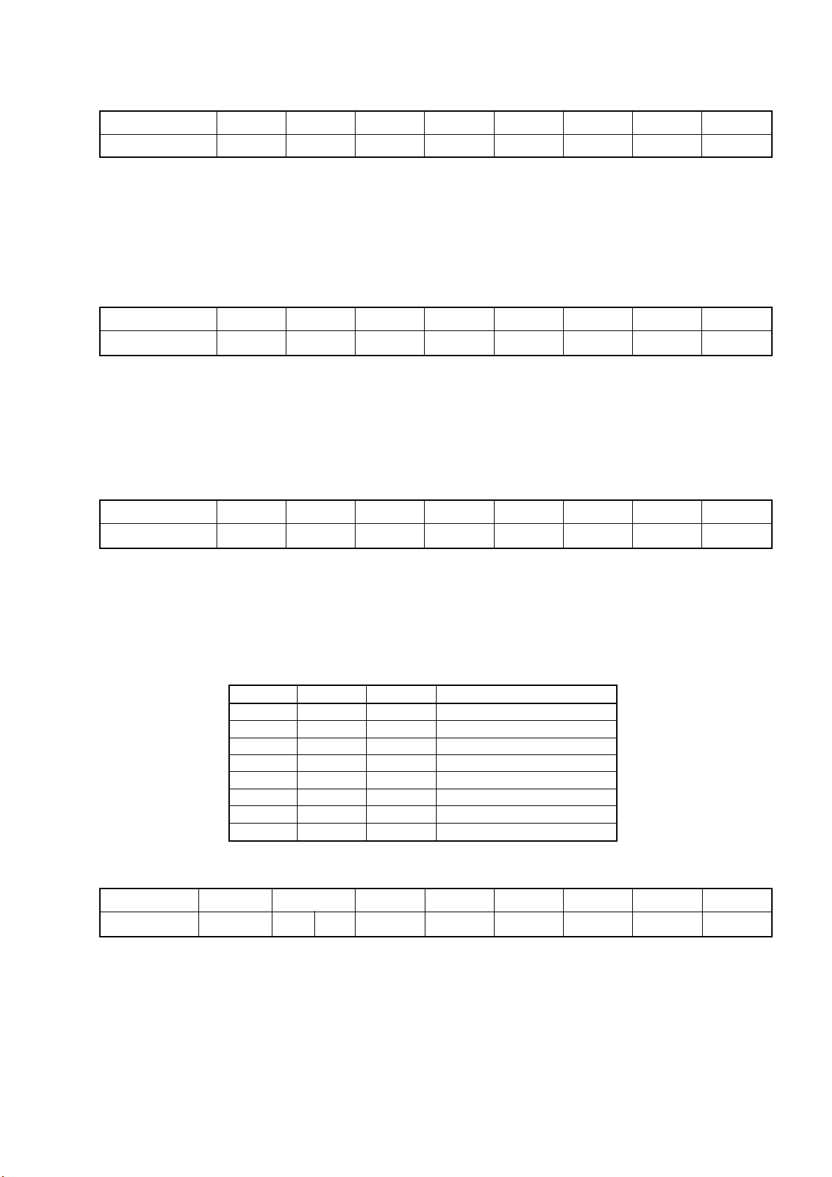
CL2 CL1 CL0 Cathode Drive amplitude
0 0 0 57V
0 0 1 63V
0 1 0 70V
0 1 1 77V
1 0 0 84V
1 0 1 91V
1 1 0 99V
1 1 1 107V
-
0
AKB
0
MAT
0
BPS
0
DS
0
CB
0
DSA
0
ACL
1
EBS
0
CL2
0
BLS
0
CL1
0
BKS
1
CL0
0
No. 4E OP1
Item
KV-HW21P80A
HA ME Vol Tone controller Volume curve setting. 1 = for HA(ME), 0 = for HA(GE)
AV Input 00 = no AV Input model 01 = 1 AV Input model
COMB (for NTSC model) 1 = Enable external comb filter, 0 =Disable external comb filter
Other optional function will be enabled if the corresponding bit is set to 1.
HA ME VOL0AV Input
01
COMB
0
10 = 2 AV Input model 11 = Not available
B/G
1
I
0
D/K
0
– 15 –
M
0
HEX
28
KV-HW21P80A
RM-969
No. 4F OP2
Item
KV-HW21P80A
No NICAM 1 = NICAM search is disable in any TV system, 0 = NICAM search operates
US ST (Reserved for NTSC model)
1 V-Curve 1 = using common volume curve for every mode and every TV system
(for monaural mode) 0 = another volume curve available for video mode and M system
XTAL SEL 00 = only 4.43 XTAL 01 = only 3.58 XTAL
Other optional function will be enabled if the corresponding bit is set to 1.
No. 50 OP3
Item
KV-HW21P80A
No Bal. 1 = no balance in analog select items, 0 = balance included
(for AV stereo model)
SPC SOUND 1 = Space Sound available, 0 = not available
Korean ST (Reserved for NTSC model)
No NICAM
1
Pict Rot.
0
US ST
0
Auto TV Sys.
0
HDEV
0
10 = not used 11 = both 4.43 and 3.58 XTAL
No Bal.
0
IV-Curve
0
SPACE SOUND
1
XTAL
11
KOREAN ST
0
VM
0
SECAM
0
H.K. BIL
2nd Lang.
Thai Bil.
0
HEX
1
0
8D
HEX
10
H.K. Bil. 1 = NICAM bilingual available (No NICAM stereo), 0 = not available
(for monaural model)
Other optional function will be enable if the corresponding bit is set to 1.
– 16 –
 Loading...