

Sony KV-DR29M67, KV-DR29M87, KV-DR29M97 Service Manual
REVISION HISTORY
AG3E
CHASSIS
MODEL
KV-DR29M67
KV-DR29M87
KV-DR29M97
NO. SUFFIX DATE SUPP / CORR DESCRIPTION
1 -01 2002/8 -- 1st. Issue
PART NO. : 9-872-330-01
SERVICE MANUAL AG3E
MODEL COMMANDER DEST. CHASSIS NO.
KV-DR29M67 RM-991 India SCC-U57C-A
KV-DR29M87 RM-991 Vietnam SCC-U85A-A
KV-DR29M97 RM-991 India SCC-U57C-A
CHASSIS
TRINITRON
®
COLOR TV

KV-DR29M67/DR29M87/DR29M97
RM-991
Power requirements 110-240V AC, 50/60 Hz
Power consumption (W) Indicated on the rear of the TV
Television system B/G, I, D/K, M
Color system PAL, PAL 60, SECAM, NTSC3.58, NTSC4.43
Stereo/Bilingual system NICAM Stereo/Bilingual B/G, I; KV-DR29M67/DR29M97
A2 Stereo/Bilingual B/G
Channel coverage
B/G VHF: E2 to E12
UHF: E21 to E69
CATV: S01 to S03, S1 to S41
I UHF: B21 to B68
CATV: S01 to S03, S1 to S41
D/K VHF: C1 to C12, R1 to R12
UHF: C13 to C57, R21 to R60
CATV: S01 to S03, S1 to S41, Z1 to Z39
M VHF: A2 to A13
UHF: A14 to A79
CATV: A-8 to A-2, A to W+4, W+6 to W+84
˘(Antenna) 75-ohm external terminal
Audio output (Speaker) 6W + 6W
3D WOOFER 15W
Number of terminal
DVideo Input: 4 Output: 1 Phone jacks; 1 Vp-p, 75 ohms
≥ Audio Input: 4 Output: 1 Phone jacks; 500 mVrms
(S Video) Input : 2 Y: 1 Vp-p, 75 ohms
(Component Input : 1 Phono jacks:
Video) Y: 1 Vp-p, 75 ohms, sync negative
2 (Headphone) Output: 1 Stereo minijack
Picture tube 29 in
Tube size (cm) 72 Measured diagonally
Screen size (cm) 68 Measured diagonally
Dimension (w/h/d,mm) 786 × 596 × 514
Mass (kg) 57
SPECIFICATIONS
Note
unbalanced, sync negative
C: 0.286 Vp-p, 75 ohms
PB/CB: 0.7 Vp-p, 75 ohms
R/CR: 0.7 Vp-p, 75 ohms
P
Audio: 500mVrms
CAUTION
SHORT CIRCUIT THE ANODE OF THE PICTURE TUBE AND
THE ANODE CAP TO THE METAL CHASSIS, CRT SHIELD,
OR CARBON PAINTED ON THE CRT, AFTER REMOVING THE
ANODE.
Design and specifications are subject to change without notice.
SAFETY-RELATED COMPONENT WARNING!!
COMPONENTS IDENTIFIED BY SHADING AND MARK ! ON
THE SCHEMATIC DIAGRAMS, EXPLODED VIEWS AND IN
THE PARTS LIST ARE CRITICAL TO SAFE OPERATION.
REPLACE THESE COMPONENTS WITH SONY PARTS
WHOSE PART NUMBERS APPEAR AS SHOWN IN THIS
MANUAL OR IN SUPPLEMENTS PUBLISHED BY SONY.
– 2 –

TABLE OF CONTENTS
KV-DR29M67/DR29M87/DR29M97
RM-991
Section Title Page
SELF DIAGNOSTIC FUNCTION..................................4
1. DISASSEMBLY
1-1. Rear Cover Removal ..................................................7
1-2. 3D Speaker Box Removal .......................................... 7
1-3. Speaker Removal........................................................ 7
1-4. Chassis Assy Removal................................................ 7
1-5. Service Position .......................................................... 7
1-6. Service Position on TV Stand .................................... 8
1.7. Terminal Bracket Removal......................................... 8
1-8. B3 and D5 Boards Removal....................................... 8
1-9. F1 Board Removal...................................................... 8
1-10. BC1, P and V2 Boards Removal................................ 8
1-11. H1 and H2 Boards Removal.......................................9
1-12. A and D Board Removal ............................................ 9
1-13. Picture Tube Removal ................................................ 9
2. SERVICE JIG
2-1. Jigs Required for Servicing...................................... 11
3. CIRCUIT BOARDS LOCATION ................................. 11
4. ADVANCE OPERATION
4-1. "RESET" Function ................................................... 12
5. SET-UP ADJUSTMENTS
5-1. Beam Landing .......................................................... 13
5-2. Convergence Adjustment .........................................14
5-3. Focus Adjustment ..................................................... 16
5-4. Neck Assy Twist Adjustment ................................... 16
5-5. G2 (SCREEN) and White Balance Adjustments ..... 16
Section Title Page
7. DIAGRAMS
7-1. Block Diagram ......................................................... 40
7-2. Schematic Diagrams................................................. 49
(1) A Board Schematic Diagrams ............................ 50
(2) B3 Board Schematic Diagram............................ 54
(3) D Board Schematic Diagram..............................56
(4) D5 Board Schematic Diagram ........................... 58
(5) C Board Schematic Diagram.............................. 60
(6) P Board Schematic Diagram .............................. 62
(7) BC1 Board Schematic Diagram ......................... 64
(8) H1 Board Schematic Diagram ........................... 66
(9) H2 and J Boards Schematic Diagram ....................
(10) F1 and VM Boards Schematic Diagram ..............
7-3. Voltage Measurement and Waveforms.........................
7-4. Printed Wiring Boards and Parts Location ..................
7-5. Semiconductors ...................................................... 102
8. EXPLODED VIEWS
8-1. Speaker Bracket...................................................... 105
8-2. 3D Speaker .............................................................105
8-3. Chassis .................................................................... 106
8-4. Picture Tube............................................................ 107
9. ELECTRICAL PARTS LIST ...................................... 108
OPERATING INSTRUCTIONS
6. CIRCUIT ADJUSTMENTS
6-1. Adjustments With Commander ................................ 17
6-2. Adjustment Method .................................................. 17
6-3. Picture Quality Adjustments .................................... 36
6-4. Sub Hue/Col Adjustment.......................................... 36
6-5. Deflection Adjustments ............................................ 37
6-6. A Board Adjustment After IC003 (MEMORY)
Replacement ............................................................. 38
6-7. Picture Distortion Adjustment.................................. 39
– 3 –

KV-DR29M67/DR29M87/DR29M97
RM-991
SELF DIAGNOSTIC FUNCTION
The units in this manual contain a self-diagnostic function. If an error occurs, the STANDBY/TIMER lamp will automatically
begin to flash.
The number of times the lamp flashes translates to a probable source of the problem. A definition of the STANDBY/TIMER
lamp flash indicators is listed in the instruction manual for the user’s knowledge and reference. If an error symptom cannot
be reproduced, the remote commander can be used to review the failure occurrence data stored in memory to reveal past
problems and how often these problems occur.
1. DIAGNOSTIC TEST INDICATORS
When an error occurs, the STANDBY/TIMER lamp will flash a number of times to indicate the possible cause of the
problem. If there is more than one error, the lamp will identify the first of the problem areas.
Result for all of the following diagnostic items are displayed on screen. No error has occured if the screen displays a “0”.
Diagnostic
Item
Description
• Power does not
turn on
• +B overcurrent
(OCP)
• +B overvoltage
(OVP)
• Vertical deflection
failure
• White balance
failure (no
PICTURE)
• Horizontal
deflection failure
• Micro reset
Note 1: Refer to screen (G2) Adjustment in section 5-5 of this manual.
No. of times
STANDBY/TIMER
lamp flashes
Does not light
2 times
3 times
4 times
5 times
6 times
—
Self-diagnostic
display/Diagnostic
result
—
002:000 or
002:001~255
003:000 or
003:001~255
004:000 or
004:001~255
005:000 or
005:001~255
006:000 or
006:001~225
101:00 or
101:001~225
• Power cord is not plugged
in.
• Fuse is burned out F1601
(F1 Board)
• H.OUT Q6807 is shorted.
• H.IN Q6810 is shorted.
Q6802 shorted.
• PH6602 faulty.
D6644 faulty, R6651 open.
• 10.5V is not supplied.
(D board)
• V.OUT IC6800 faulty
D6816 faulty
D6817 faulty
D6824 faulty
R6852 open
R6851 open (D board)
• G2 is improperly adjusted.
(Note 2)
• CRT problem.
• Video OUT IC9001, 9002,
9003 are faulty. (C board)
• IC8306 (A board) and
IC4301 (A board) are faulty.
• C6831 is open circuit.
PS6606 open, PS6605
open. (D board)
• CRT Discharge (C Board)
• Static discharge
• Exter nal noise
Probable
Cause
Location
Detected
Symptoms
• Power does not come on.
• No power is supplied to the
TV.
• AC power supply is faulty.
• Power does not come on.
• Load on power line is
shorted.
• Power does not come on.
• Vertical deflection pulse is
stopped.
• Vertical size is too small.
• Vertical deflection stopped.
• No raster is generated.
• CRT cathode current
detection reference pulse
output is small.
• H pulse output is too high.
• Power is shut down shortly,
after this return back to
normal.
• Detect Micro latch up.
– 4 –
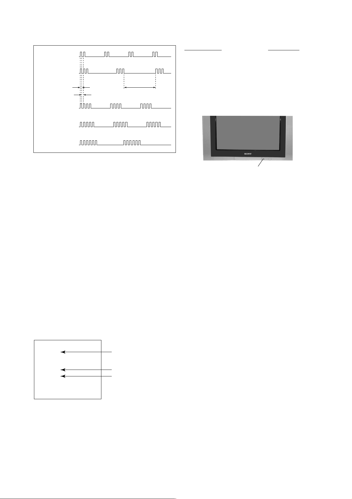
2. DISPLAY OF STANDBY/TIMER LIGHT FLASH COUNT
2 times
3 times
Lamp ON 0.3 sec.
Lamp OFF 0.3 sec.
Lamp OFF 3 sec.
KV-DR29M67/DR29M87/DR29M97
RM-991
Diagnostic Item Flash Count*
+B overcurrent 2 times
+B overvoltage 3 times
V deflection stop 4 times
White balance failure 5 times
Horizontal Deflection Failure 6 times
4 times
5 times
6 times
* One flash count is not used for self-diagnostic.
STANDBY/SLEEP lamp
3. STOPPING THE STANDBY/TIMER FLASH
Turn off the power switch on the TV main unit or unplug the power cord from the outlet to stop the STANDBY/TIMER lamp
from flashing.
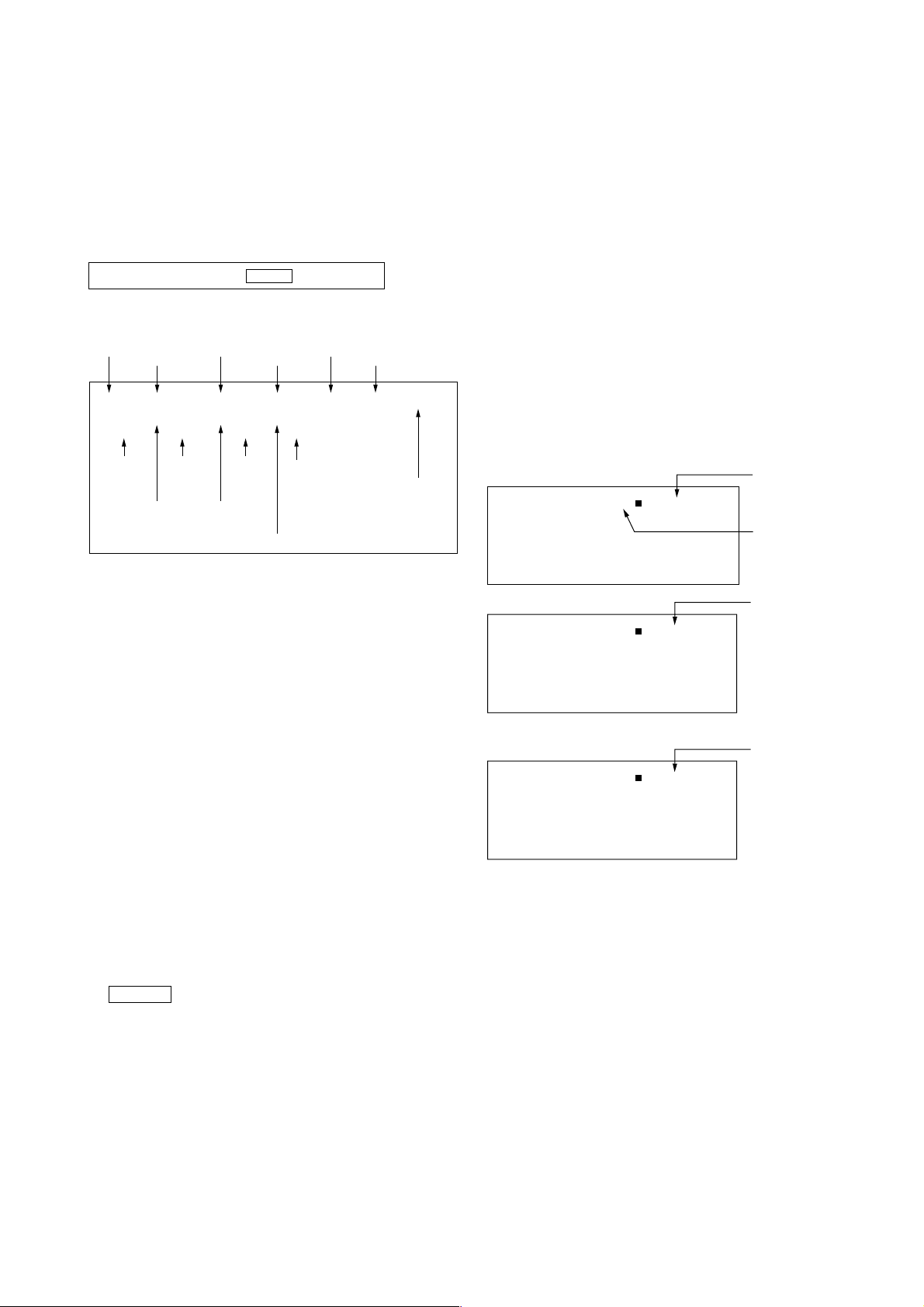
4. SELF-DIAGNOSTIC SCREEN DISPLAY
For errors with symptoms such as “power sometimes shuts off” or “screen sometimes goes off” that cannot be confirmed, it
is possible to bring up past occurances of failure for confirmation on the screen:
[To Bring Up Screen Test]
In standby mode, press buttons on the remote commander sequentially in rapid succession as shown below:
[Screendisplay] / channel [5] / Sound volume [-] / Power ON
˘
Note that this differs from entering the service mode (mode volume [+]).
Self-Diagnosis screen display
SELF DIAGNOSTIC
002 : 000
003 : 000
004 : 000
005 : 001
006 : 002
101 : 000
Numeral "0" means that no fault has been detected.
Numeral "1" means a fault has been detected.
Numeral "2" means two faults have been detected.
– 5 –
KV-DR29M67/DR29M87/DR29M97
RM-991
5. HANDLING OF SELF-DIAGNOSTIC SCREEN DISPLAY
Since the diagnostic results displayed on the screen are not automatically cleared, always check the self-diagnostic screen
during repairs. When you have completed the repairs, clear the result display to “0”.
Unless the result display is cleared to “0”, the self-diagnostic function will not be able to detect subsequent faults after
completion of the repairs.
[Clearing the result display]
To clear the result display to “0”, press buttons on the remote commander sequentially as shown below when the diagnostic
screen is being displayed.
Channel [8] / 0
[Quitting Self-diagnostic screen]
To quit the entire self-diagnostic screen, turn off the power switch on the remote commander or the main unit.
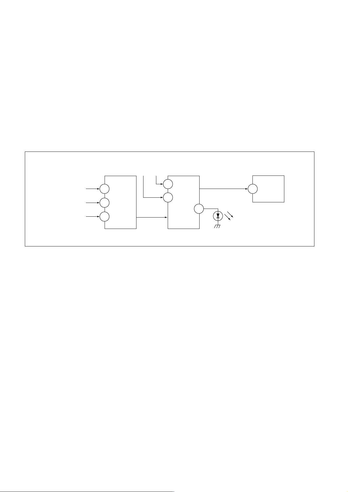
6. SELF-DIAGNOSTIC CIRCUIT
FROM
CRT (IK)
[H] D6825, D6830
[V] Q6819, R6832
IC4301
RGB JUNGLE
IKIN
34
H PROT
35
V PROT
CXA2150AQ
OVP OCP
SDA
SYSTEM
3
6
IC001
LED 1
54
SDA
IC003
MEMORY
558
[+BovercurrentªOCPº] Occurs when an overcurrent on the +B(135) line is detected by Q6610
and Q6609.
If Q6610 and Q6609 go to ON, the voltage to the pin3 of IC001 go to UP.
The unit will automatically turn off.
[+BovervoltageªOVPº] Occurs when an overvoltage on the +B(135) line is detected by D6635
and Q6611. If Q6611 go to ON, the voltage to pin6 of IC001 go to UP. The
unit will automatically turn off.
[Verticaldeflectionfailure] Occurs when an absence of the vertical deflection pulse is detected by
Q6819 and R6832. Shut down the power supply.
[Whitebalancefailure] If the RGB levels do not balance or become low level within 5 seconds.
This error will be detected by IC4301.
TV will stay on, but there will be no picture.
[HighvoltageprotectorofHorizontalDeflection] Occurs when an overvoltage of horizontal pulse is detected by D6809 and
IC6801.
If the voltage of anode D6830, Q6800 and D6825 goes to High, the
voltage to pin34 of IC4301 go to UP. The unit will automatically turn off.
– 6 –
SECTION 1
DISASSEMBLY
KV-DR29M67/DR29M87/DR29M97
RM-991
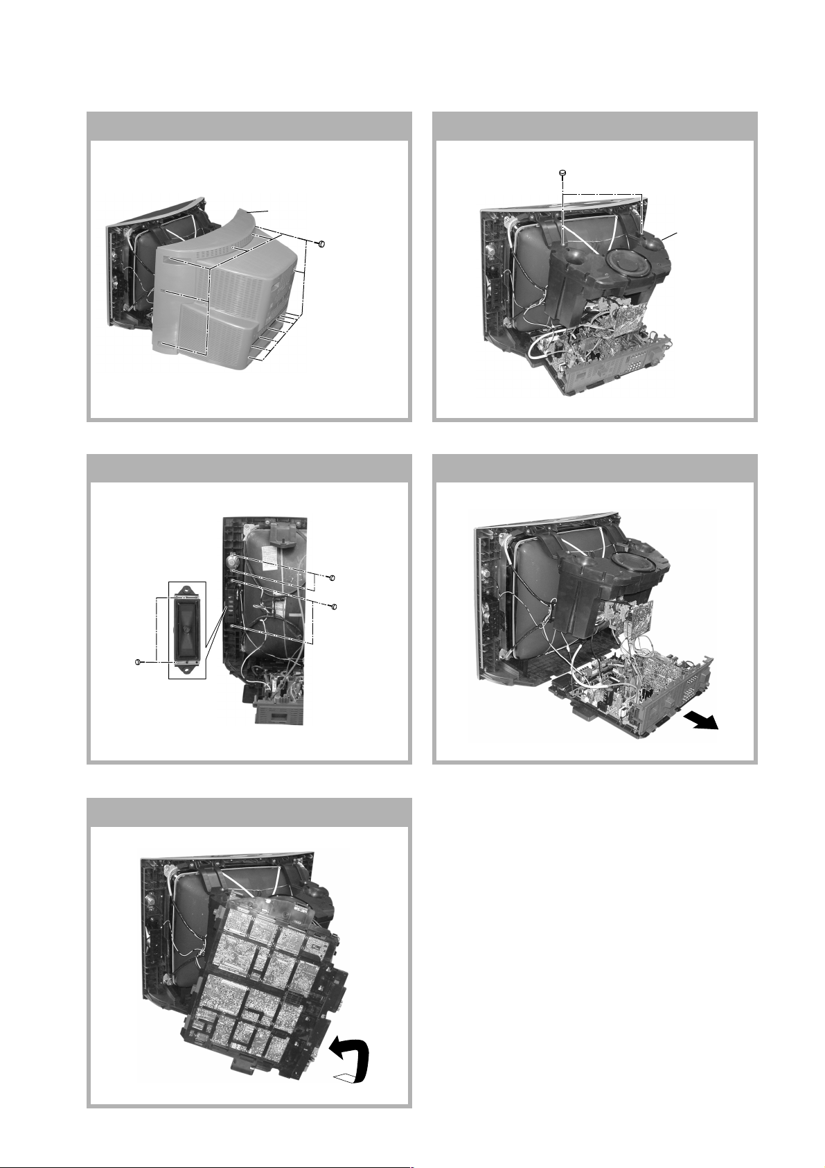
1-1. REAR COVER REMOVAL
2 Rear cover
1 Fourteen screws
(+BVTP 4 × 16)
1-2. 3D SPEAKER BOX REMOVAL
1 Two screws
(TP+TWH 4 × 25)
1-3. SPEAKER REMOVAL 1-4. CHASSIS ASSY REMOVAL
2 3D Speaker
box assy
3 Two screws
(+BVTP 4 × 16)
1-5. SERVICE POSITION
1 Two screws
(+BVTP 4 × 16)
2 Two screws
(Washer Head)
(+P4x16)
– 7 –
KV-DR29M67/DR29M87/DR29M97
RM-991
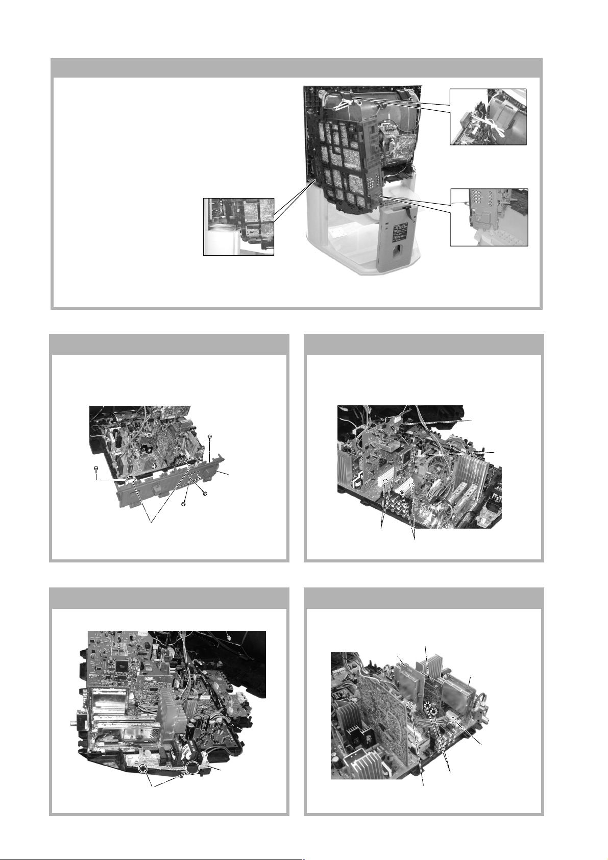
1-6. SERVICE POSITION ON TV STAND
Note:•1)Remove the Rear Cover (refer 1-1)
- unscrew all 14 screws fixed on the Rear Cover. Hold
the top of the TV Cabinet; lift the Rear Cover slightly
upwards to release the Rear Cover foot from the TV
Stand and slide it backwards from the TV Cabinet.
2)Remove the 3D Speaker Box (refer 1-2)
3)Release the Lead Assy Speaker (left side)
4)Lift up the chassis and place it in the Service
Position as shown:-
Caution: 1) In Service Position, make
sure all the TV connections
are connected correctly
before turning on the TV
set.
2) The TV on the TV Stand
without Rear Cover is
unstable. As such be
careful not to push the TV
Place the front of the main
bracket on to the foot of the
TV Cabinet
foward or backward
1-7. TERMINAL BRACKET REMOVAL
Use a non elastic and non
conductive string to tie the
main bracket to the woofer
bracket
Place the Terminal
Bracket edge into the hole
on the TV Stand foot
1-8. B3 AND D5 BOARDS REMOVAL
Note: Access to the B3 board is possible after removal
of the shiledcase. Remove the shiledcase by
removing 2 screws +BVTP 3x16
2 D5 Board
3 One screw
(+BVTP 3 × 12)
3 One screw
(+BVTP 3 × 12)
5 Terminal bracket
2 Two screws
(+BVTP 3 × 12)
1 Two clips
3 Two clips
4 Two hooks
1 One screw
(+BVTP 4 × 16)
1-9. F1 BOARD REMOVAL 1-10. BC1 AND P BOARDS REMOVAL
2 BC1 Board
4 V2 Board (Not used for this models)
6 P Board
4 B3 Board
1 Two hooks
2 F1 Board
5 One clip
3 Two clips
1 One clip
– 8 –
KV-DR29M67/DR29M87/DR29M97
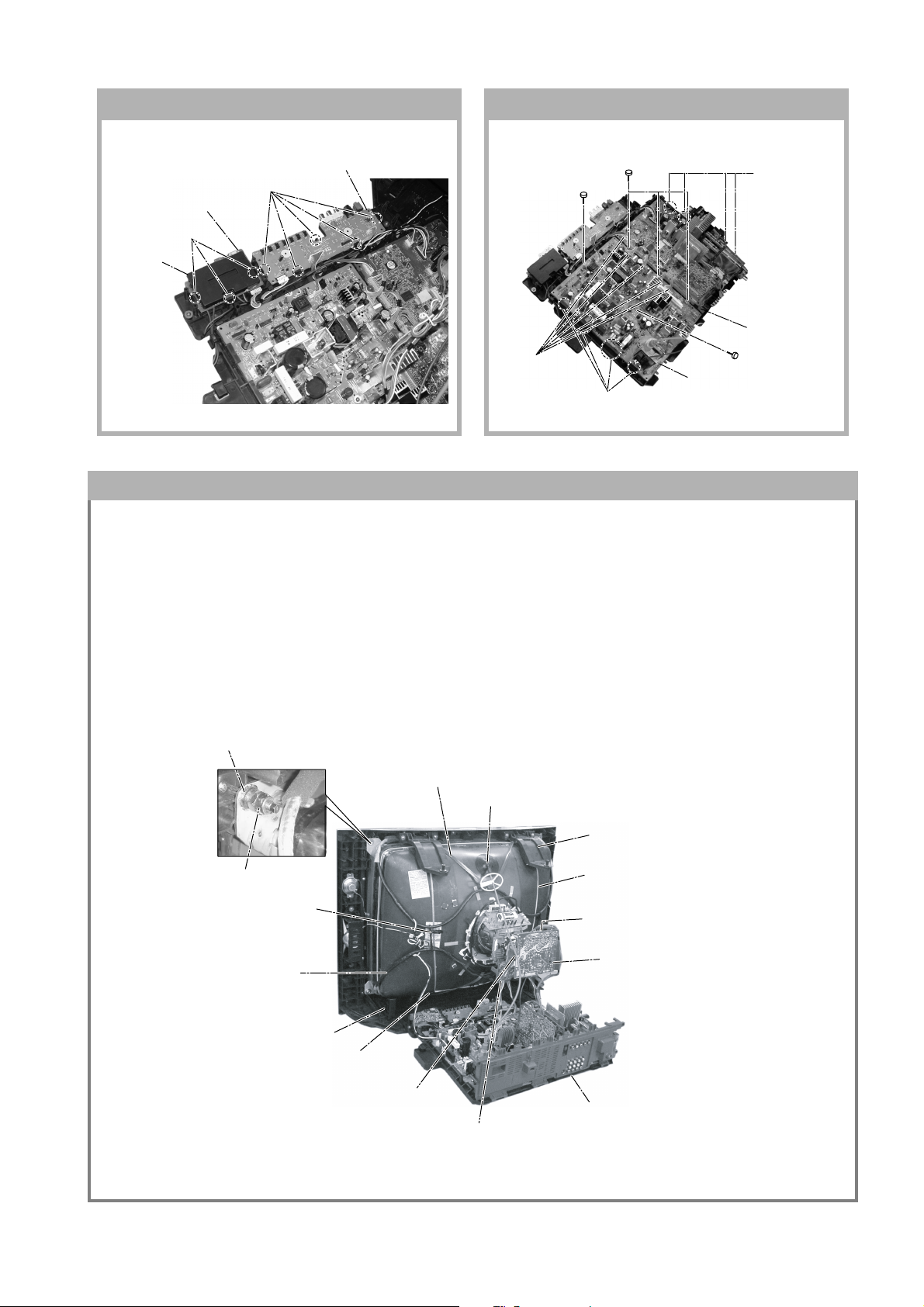
1-11. H1 AND H2 BOARDS REMOVAL 1-12. A AND D BOARDS REMOVAL
RM-991
2 Three screws
(3 × 12)(+) BVTP
7 D Board
3 Four hooks
4 A Board
5 One screw
(3 × 12)(+) BVTP
3 Three hooks
4 Cover, H
5 H2 Board
1 Five hooks
2 H1 Board
5 One screw
(3 × 12)(+) BVTP
1 Five connectors
6 Four hooks
1-13. PICTURE TUBE REMOVAL
Note:
• Please make sure the TV set is not in standing position before remo ving necessary CRT support located on bottom
right and left.
• When removing the Nut Locking: first make sure to hold the Nut special CRT with a spanner while opening the Nut
Locking using a torque driver. Then proceed to remove the Nut special CRT using a torque driver.
1)Place the TV set with the CRT face down on a cushion (jig).
2)Removal the Rear Cover.
3)Removal the 3D Box.
4)Unplug all interconnecting leads from the Deflection Yoke, Neck Assy, Degaussing Coils and CRT grounding strap.
+ Nut special CRT (4)
~ Nut, Locking (4)
% Holder, DGC(2) Removal
& DGC(2) Removal
# Supports, CRT(2) Removal
$ Band, DGC(1) Removal (only top-side)
( Spring Tension(2)
Removal
9 Loosen the Deflection Yoke
fixing screw and remove
5 Anode Cap Removal
" Bracket Woofer(2) Removal
) Earth Coating Assy(2) Removal
7 Loosen the Neck Assembly
fixing screw and remove
6 C Board Removal
! Chassis Assy Removal
8 VM Board Removal
– 9 –
KV-DR29M67/DR29M87/DR29M97
RM-991
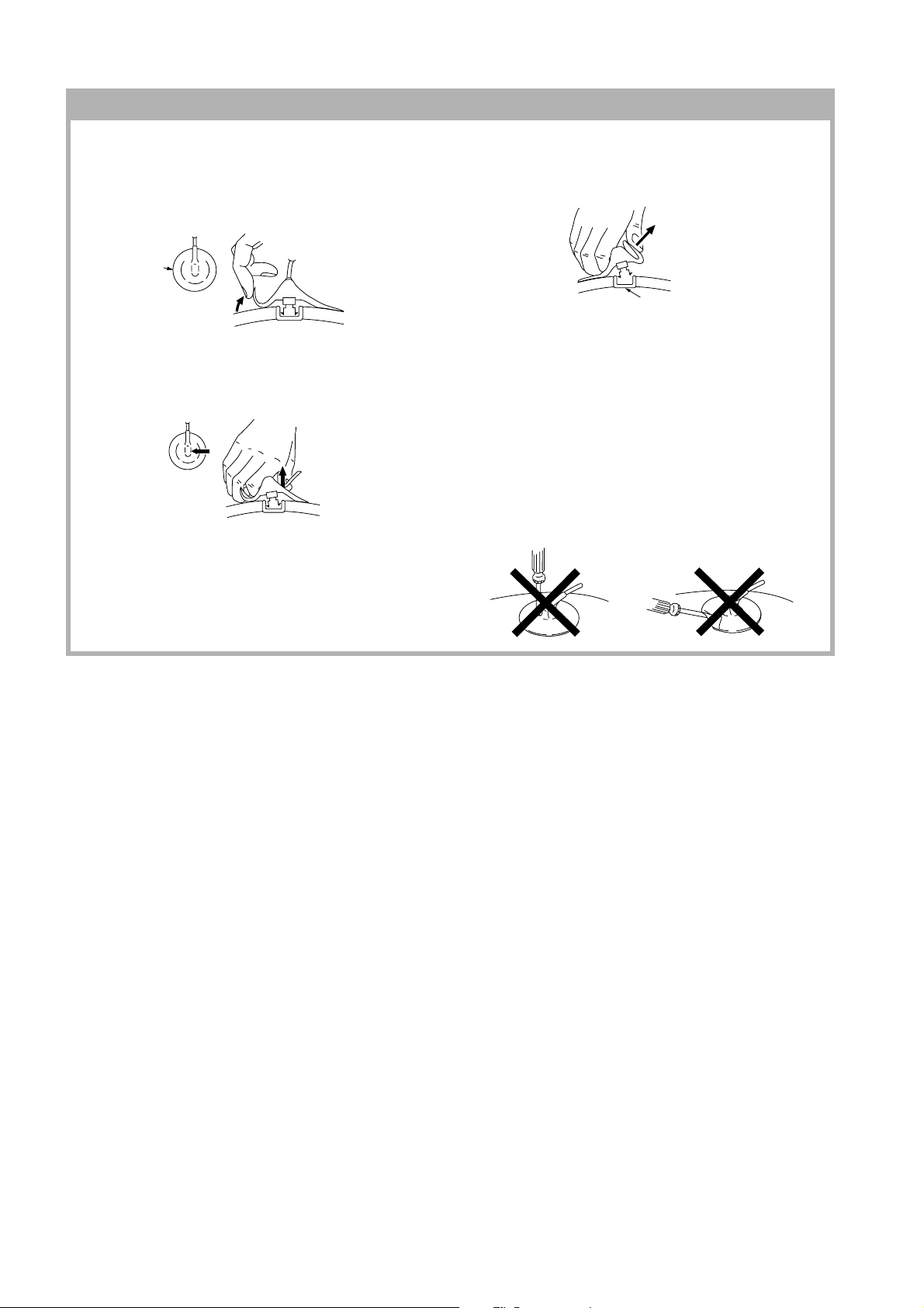
• REMOVAL OF ANODE-CAP
Note:
• After removing the anode, short circuit the anode of the picture tube and the anode cap to the metal chassis, CRT
shield or carbon paint on the CRT.
• REMOVING PROCEDURES
a
c
a
1 Turn up one side of the rubber cap in the direction
indicated by the arrow a.
b
b
2 Using a thumb pull up the rubber cap firmly in the direc-
tion indicated by the arrow b.
Anode Button
3 When one side of the rubber cap is separated from the
anode button, the anode-cap can be removed by
turning up the rubber cap and pulling it up in the
direction of the arrow c.
• HOW TO HANDLE AN ANODE-CAP
1 Do not damage the surface of anode-caps with
sharp shaped objects.
2 Do not press the rubber too hard so as not to
damage the inside of anode-cap.
A metal fitting called the shatter-hook terminal is
built into the rubber.
3 Do not turn the foot of rubber over too hard.
The shatter-hook terminal will stick out or damage
the rubber.
– 10 –
KV-DR29M67/DR29M87/DR29M97
SECTION 2
SERVICE JIG
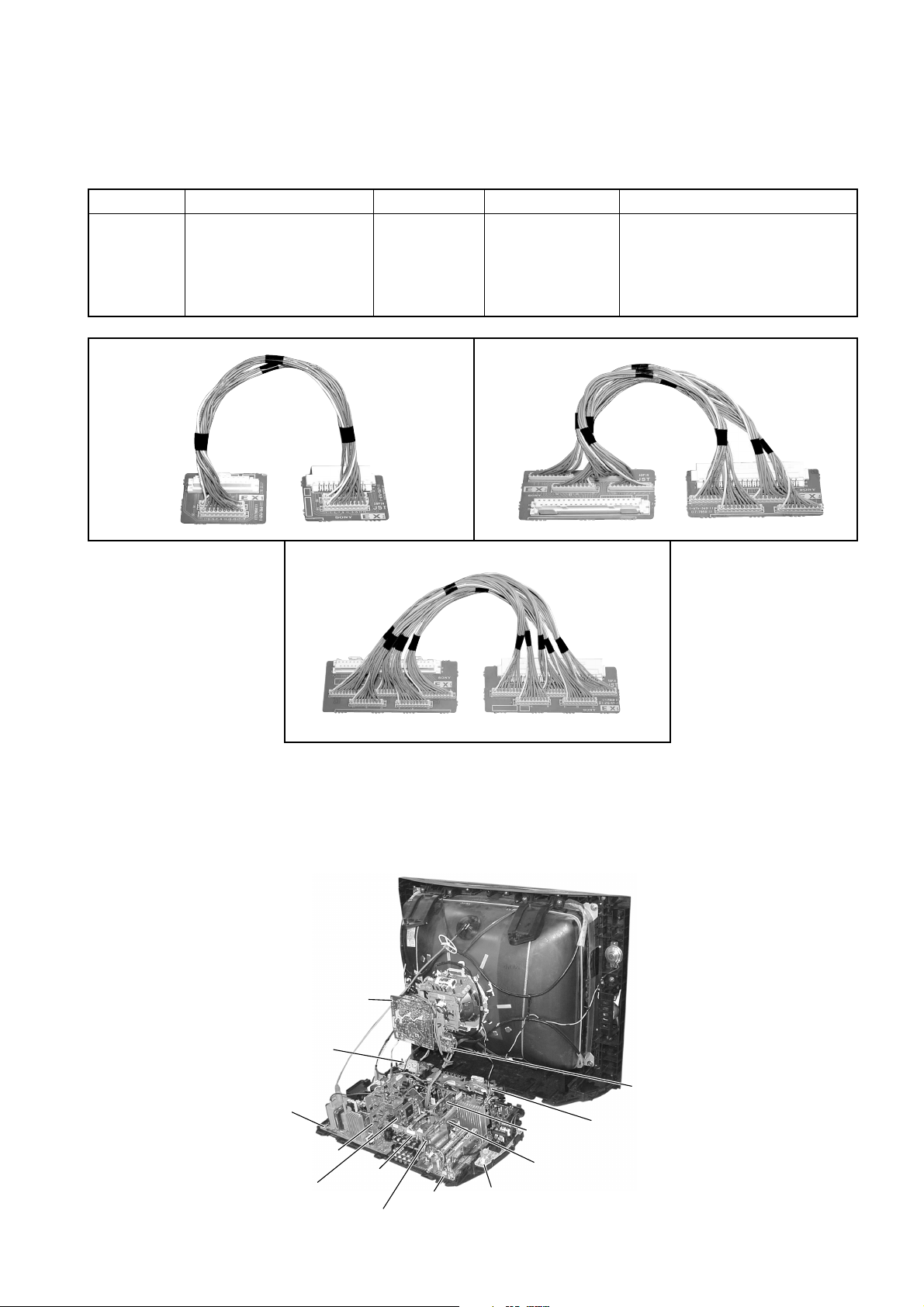
2-1. JIGS REQUIRED FOR SERVICING
REF NO. DESCRIPTION QUANTITY PART NO. REMARK
J-1 TOOL(20P),SERVICE 1 3-702-763-01 For A to BC1 board extension
1 For A to P board extension
J-2 TOOL(40P),SERVICE 1 3-702-764-01 For A to B3 board extension
J-3 TOOL(50P-A),SERVICE 1 3-702-765-01 For D to D5 board extension
J-1 J-2
RM-991
J-3
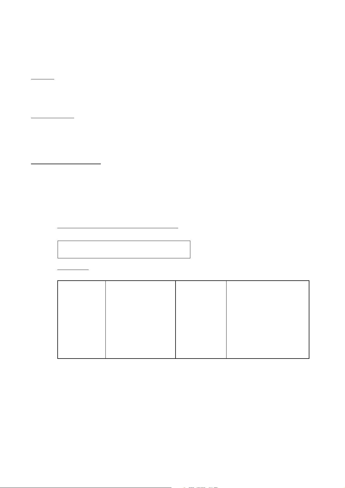
SECTION 3
CIRCUIT BOARDS LOCATION
C Board
H2 Board
D Board
D5 Board
B3 Board
J Board
P Board
A Board
F1 Board
– 11 –
VM Board
BC1 Board
V2 Board
(Not used for this models)
H1 Board
KV-DR29M67/DR29M87/DR29M97
RM-991
SECTION 4
ADVANCE OPERATION
4-1. "RESET" FUNCTION
1. Purpose
If a customer faces some setting problem that cannot be solved, using the "RESET" function some items will be
reset to its original setting (shipping condition)
2. How to Operate
There are 2 ways to access to the "RESET" Function:-
a) By pressing "RESET" button on the Remote Commander.
b) By pressing "MENU" button on the Front Key Input and hold it down for 5 seconds.
3. Subsequent of Operation
Sequential to the resetting operation (either methods being used in No. 2), TV set would shut down once and
automatically turn on again. The power-off duration is expected to be about 500msec. An OSD message,
"RESET" tentatively will be displayed for 10 sec after IK status gets stable.
As a result, some items will be reset to an initial condition (shipment condition) wheareas some other remains at
the last selection by user.
Items that remains at the last selection by user
Program No., PIC rotation, OSD Language,
Fine tuning, TV System, Skip
Reset Items
Video input RF
Volume 30
DRC-MF DRC1250
Picture mode DYNAMIC
Sound mode DYNAMIC
Surround mode OFF
Color system(video) AUTO
Multi picture(PIP) OFF
PIP position Bottom-right
OSD recall OFF
Intelligent volume OFF
ECO mode OFF
Color system(RF) AUTO*
*= only when in RF mode
Antenna sensitivity HIGH*
Stereo mode STEREO/NICAM*
Bilingual mode MAIN*
High-deviation mode AUTO*
Child lock OFF*
Wide mode OFF
Game mode OFF
Teletext mode OFF
Sleep timer OFF
Wake-up timer OFF
Sound muting OFF
3DNR ON
Except
KV-DR29M87
}
– 12 –
SECTION 5
Purity control
corrects this area.
Disk magnets or rotatable
disk magnets correct these
areas (a-d).
Deflection yoke positioning
corrects these areas.
a
b
b
c
c
d
d
a
SET-UP ADJUSTMENTS
KV-DR29M67/DR29M87/DR29M97
RM-991
• The following adjustments should be made when a complete
realignment is required or a new picture tube is installed.
• These adjustments should be performed with rated power
supply voltage unless otherwise noted.
Perform the adjustments in the following order :
1. Beam Landing
2. Convergence
3. Focus
4. White Balance
Controls and switches should be set as follows unless otherwise
noted:
PICTURE control........................................................... normal
BRIGHTNESS control................................................... normal
................................................................................................................................................................................................................................
Note : Test Equipment Required.
1. Color-bar/Pattern Generator
2. Degausser
3. Oscilloscope
Preparation :
• In order to reduce the influence of geomagnetism on the set's
picture tube, face it east or west.
• Switch on the set's power and degauss with the degausser.
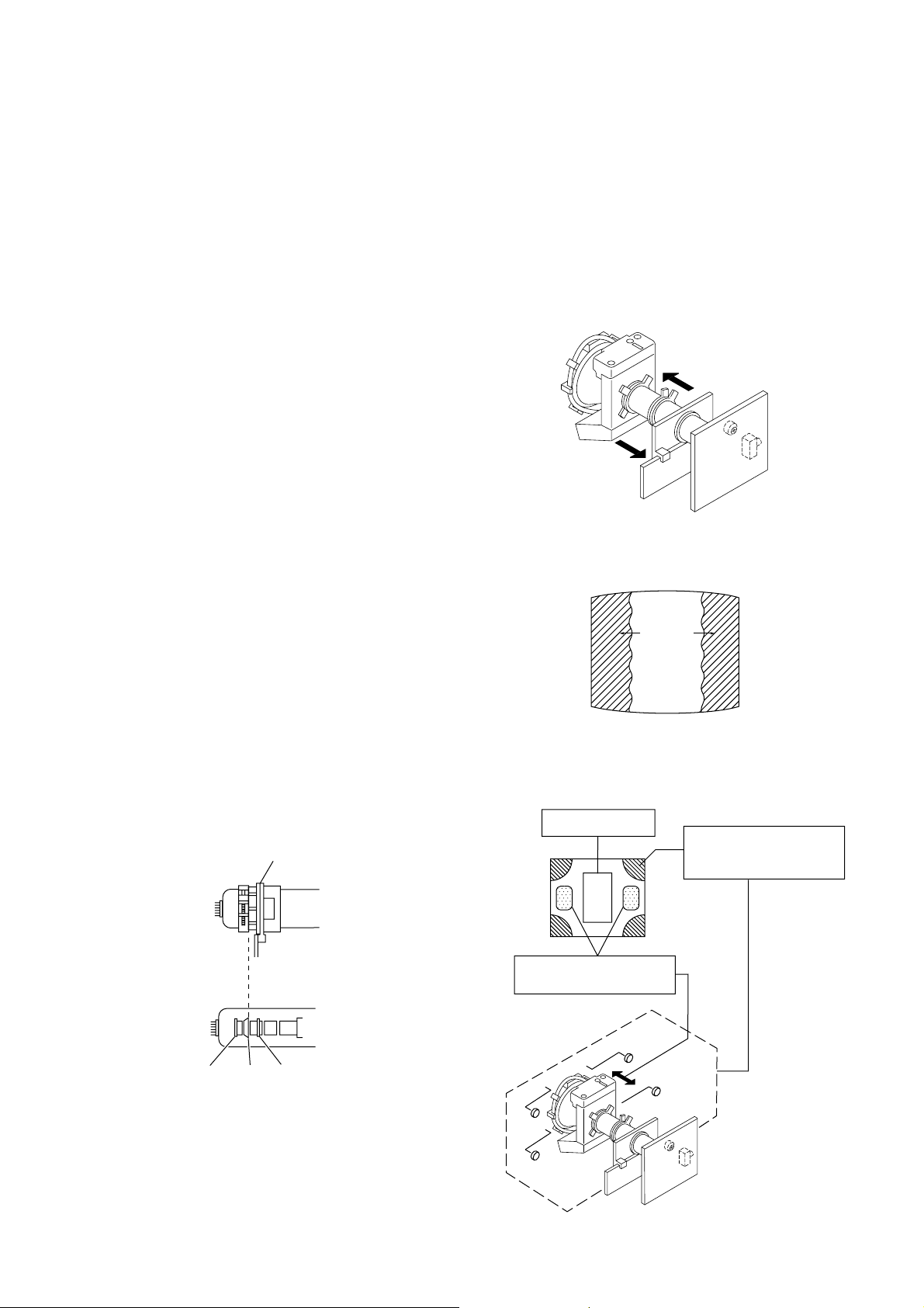
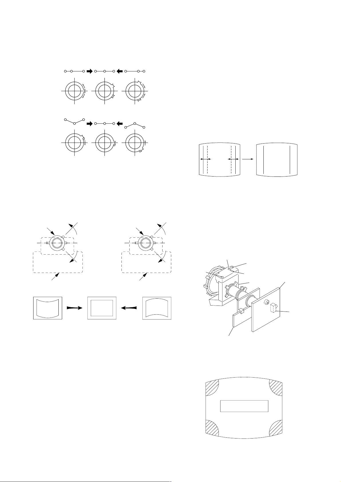
5-1. BEAM LANDING
1. Input a white signal with the pattern generator.
Contrast
Brightness
2. Position neck assy as shown in Fig 5-1.
3. Set the pattern generator raster signal to a green raster.
4. Move the deflection yoke to the rear and adjust with the
purity control so that the green is at the center and the blue
and the red take up equally sized areas on each side.
(See Figures 5-1 through 5-3.)
5. Move the deflection yoke forward and adjust so that the
entire screen is green. (See Figure 5-2.)
6. Switch the raster signal to blue, then to red and verify the
condition.
7. When the position of the deflection yoke has been decided,
fasten the deflection yoke with the screws and DY spacers.
8. If the beam does not land correctly in all the corners, use a
magnet to adjust it.
(See Figure 5-4.)
}
normal
Fig. 5-2
Blue
Red
Green
Fig. 5-3
Neck assy
G2G1 G3
Fig. 5-1
Align the edge of
the neck assy with
the edge of the G2 grid.
Fig. 5-4
– 13 –
KV-DR29M67/DR29M87/DR29M97
RM-991
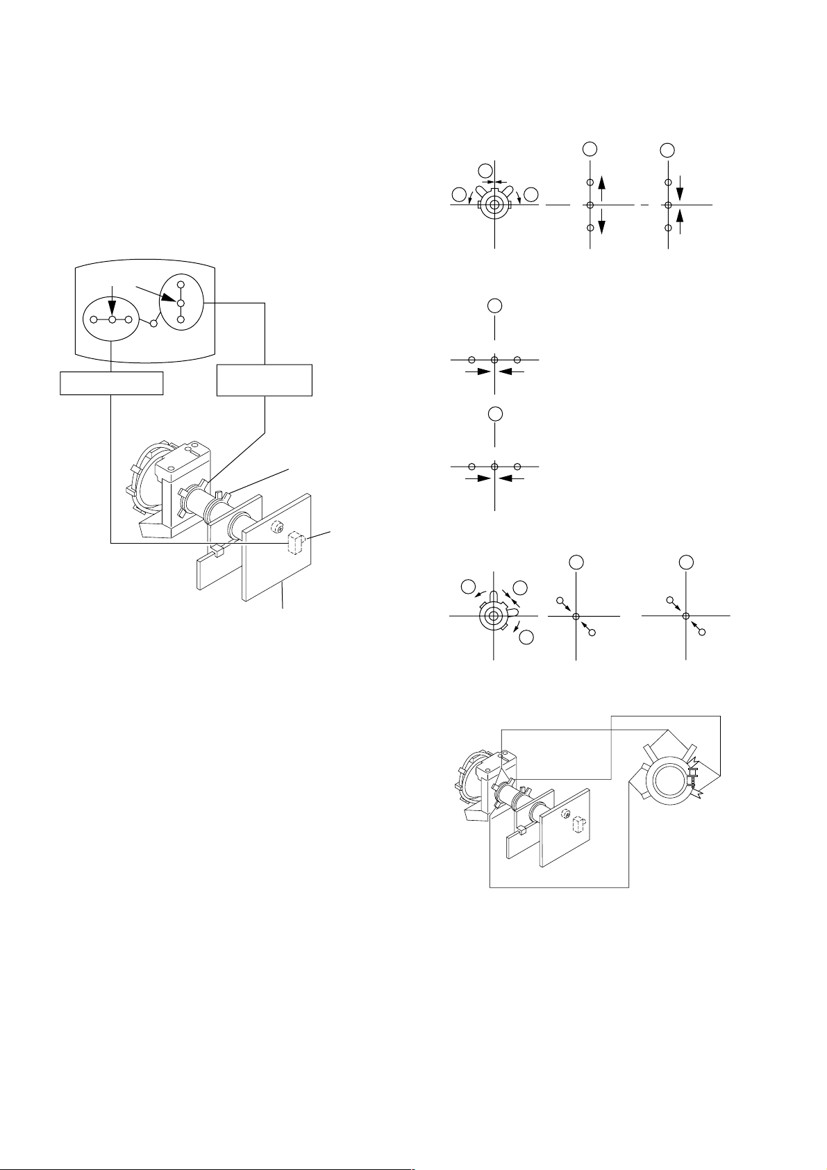
5-2. CONVERGENCE ADJUSTMENT
Preparation :
• Before starting this adjustment, adjust the focus, horizontal
size and vertical size.
• Receive cross hatch/dot pattern and set picture mode to
"STANDARD".
(1) Horizontal and Vertical Static Convergence
1 V. STAT
b b
a
a
B
G
R
b
B
G
R
Center dot
R G B
H. STAT VR
R
G
B
V. STAT
Magnet
Y magnet
RV702
H. STAT
C Board
2 H. STAT VR
a
RGGBB
b
3
b
R
a
a
R
b
B
b
B
GG
R
1. (Moving horizontally), adjust the H.STAT control so that the
red, green and blue dots are on top of each other at the center
of the screen.
2. (Moving vertically), adjust the V.STAT magnet so that the
red, green and blue dots are on top of each other at the center
of the screen.
3. Adjust Horizontal Trapezoid with “GEO 11 HTR” in Service
Mode to make H-Trapezoid distortion best.
4. If the H.STAT variable resistor cannot bring the red, green
and blue dots together at the center of the screen, adjust the
horizontal convergence with the H.STAT variable resistor and
the V.STAT magnet in the manner given below.
(In this case, the H.STAT variable resistor and the V.STAT
magnet influence each other, so be sure to perform
adjustments while tracking.)
BMC (Hexapole)
Purity
V.STAT
– 14 –
KV-DR29M67/DR29M87/DR29M97
RM-991
4 BMC (Hexapole) Magnet.
If the red, green and blue dots are not balanced or aligned,
then use the BMC magnet to adjust in the manner described
below.
RG B R G B R GB
RB
G
RG
GB
RB
5 Y separation axis correction magnet adjustment.
1. Receive the cross-hatch signal and adjust [PICTURE] to
[MIN] and [BRIGHTNESS] to [STANDARD] .
2. Adjust the Y separation axis correction magnet on the neck
assembly so that the horizontal lines at the top and bottom of
the screen are straight.
Neck assy Neck assy
Blue
Red
(2) Dynamic Convergence Adjustment
Preparation:
• Before starting this adjustment, adjust the horizontal static
convergence and the vertical static convergence
• Set the PICTURE and BRIGHTNESS to normal.
1. Adjust TLH. (TLH convergence piece)
1 Receive the dot/hatch pattern signal and adjust picture quality
by the menu.
2 Correct horizontal mis-convergence of red and blue of both
sides on the X axis.
When red is outside insert TLH convergence piece to right
side (TLH +) views from DY neck. And when blue is outside,
insert it to left side (TLH –) and take both sides.
R
(B)B(R)
(R)
B
TLH +
R
(B)
TLH -
2. Adjust XCV core.
To able to become balance of XCV on the X axis well.
3. Adjust V-TILT.
Correct the vertical mis-convergence of red and blue of
vertically sides on the Y axis.
4. Adjust YCH.
Adjust horizontal mis-convergence of red and blue of
vertically sides on the Y axis. Mentioned above steps 2 to 4
are adjusting respectively perform minuteness tracking.
VM board
Red
VM board
Blue
Note
1. The Red and Blue magnets should be equally far from the
horizontal center line.
2. Do not separate the Red and Blue magnets too far. (Less than
8 mm)
YCH
TLV2
VM board
TLV1
(3) Screen-corner Convergence
ba
a-d : screen-corner
misconvergence
XCV
BMC magnet
C board
RV9001
– 15 –
cd
KV-DR29M67/DR29M87/DR29M97
RM-991
Fix a Permalloy assy corresponding to the
misconverged areas.
a
d
Permalloy assembly
b
c
5-3. FOCUS ADJUSTMENT
Note
Focus adjustment should be completed before W/B adjustment.
(1) Receive digital monoscope pattern.
(2) Set "A/V CONTROL" to "STANDARD".
(3) Adjust FOCUS VR so that the center of the screen becomes
just focus.
(4) Change the receiving signal to white pattern and blue back.
(5) Confirm MAGENTA RING is not noticeable. In case
MAGENTA RING is obvious, adjust FOCUS VR to balance
between MAGENTA RING and FOCUS adjustment.
5-4. NECK ASSY TWIST ADJUSTMENT
(1) Receive dot/hatch pattern DRC-MF, DRC1250, DYNAMIC.
(2) Turn FOCUS VR fully counter-clockwise.
(3) Confirm the dot shape at the screen center. (Fig. 5-4)
(4) Resume FOCUS VR.
Note
In case of turning NECK ASSY, loosen the screw 3 turns. Do not
move the position.
OK
Turn NECK ASSY clockwise.
Turn NECK ASSY counter clockwise.
Fig. 5-4
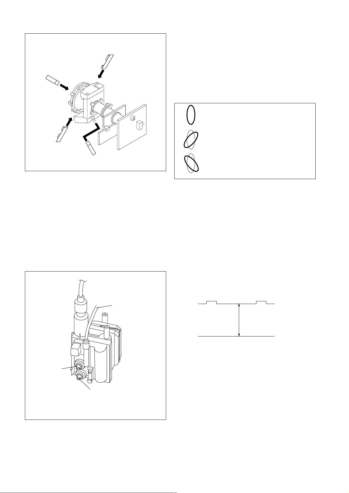
5-5. G2 (SCREEN) AND WHITE BALANCE
ADJUSTMENT
1. G2 (SCREEN) ADJUSTMENT
1) Set the PICTURE and BRIGHTNESS to normal.
2) Put to VIDEO input mode without signals.
3) Connect R, G and B of the C board cathode to the
oscilloscope.
4) Adjust BRIGHTNESS to obtain the cathode voltage to the
value below.
5) Whilst watching the picture, adjust the screen VR [RV9002]
located on the C board to the point just before the retrace
lines disappear (to the point before cut-off)
Lead Assy,
Focus
Focus
Screen
(No Function)
FLYBACK TRANSFORMER (T6803)
170 V ± 2 (VDC)
0 V
2. WHITE BALANCE ADJUSTMENT
1) Set to Service Mode (Refer Section 6-1: ADJUSTMENTS
WITH COMMANDER).
2) Input white raster signal.
3) Set the following condition.
PICTURE minimum, BRIGHTNESS 50%
4) Select GCT (WHB 08) and BCT (WHB 09) with 1 and 4,
and adjust the level with 3 and 6 for the best white
balance.
5) Set the PICTURE to maximum.
6) Select GDR (WHB 05) and BDR (WHB 06) with 1 and
4, and adjust the level with 3 and 6 for the best white
balance.
7) Write into the memory by pressing [MUTING] then -.
– 16 –
SECTION 6
29 SERVICE 50VSZ
Adjusted with [3]
and [6] buttons.
GREEN
Write with [MUTING]
Write executed with [0]
GEO 00
59 FFFF0 000A
0
1F WRITE 50VSZ
GREEN
GEO 00
59 0 000A
0
1F WRITE 50VSZ
RED
The WRITE
(red display)
return to SERVICE
(green display)
shows write is
executed.
GEO 00
59 FF 0 000A
0
048Q
1.0M
001 27E
08
1
048Q
1.0M
048Q
1.0M
001 27E
08
1
001 27E
08
1
CIRCUIT ADJUSTMENTS
KV-DR29M67/DR29M87/DR29M97
RM-991
6-1. ADJUSTMENTS WITH COMMANDER
Service adjustments to this model can be performed using the
supplied Remote Commander RM-991.
a. ENTERING SERVICE MODE
With the unit on standby
n
[DISPLAY] n 5 n VOL (+) n [POWER]
The screen display is :
Device
Name
GEO
08 1
3D NR
S/N
detection
Item No
00
048Q
Suffix No
(OEM Code)
Item
Name
VSZ 29 SERVICE
1.0M
3D NR
mode
Software version
Total Power-On time (hours)
001
H count
of SYNC
detection
Data
59 000AFF 00
27E
V count
of SYNC
detection
Marking of new NVM
Mode
p
PAL,SECAM:50
NTSC :60
50
b. CANCELLATION OF SERVICE MODE
Set the standby condition (Press [POWER] button on the commander),
then press [POWER] button again, hereupon it becomes TV mode.
6-2. ADJUSTMENT METHOD
Item Number 00 of device GEO
This explanation uses V-size as an example.
1. Select “GEO 00 VSZ” with the 1 and 4 buttons.
2. Raise/lower the data with the 3 and 6 buttons.
3. Select the optimum state. (The standard is 1F for PAL
reception.)
4. Press [MUTING] button to indicateWRITE on screen. (The
display from SERVICE (green display) to WRITE (green
display).
5. Execute the writing with the - button. (The WRITE
display changes to red color while executing and then back to
SERVICE (green display).
6. The WRITE execution is completed.
Example on screen display :-
c. METHOD OF WRITE INTO MEMORY
1) Set to Service Mode.
2) Press 1 (UP) and 4 (DOWN), to select the adjustment
item Name.
3) Press 3 or 6 to raise/lower the data value.
4) Press [MUTING] button to indicate WRITE on the screen.
5) Press - button to write into memory.
d. OTHER FUNCTION VIA REMOTE COMMANDER
7, - All the data becomes the values in memory.
8, - All goes to the standard state.
5, - Service data initialization (Be sure not to use
[DISPLAY], - Write 50Hz adjustment data to 60Hz, or vice
2, - Copy and write all data.
Cursor +/– Skip category (device) to category (device)
usually.)
versa.
example : GEO 00 VSZ
e. MEMORY WRITE CONFIRMATION METHOD
↕
DAC 00 HCT
1) After adjustment, pull out the plug from AC outlet, and then
plug into AC outlet again.
2) Turn the power switch ON and set to Service Mode.
3) Call the adjusted items again to confirm adjustments were
made.
Use the same method for all Items.
Note : 1. In [WRITE], the data for all items are written into
memory together.
2. For adjustment items that have different standard data
between 50Hz or 60Hz, be sure to use the respective
input signal after adjustment.
– 17 –
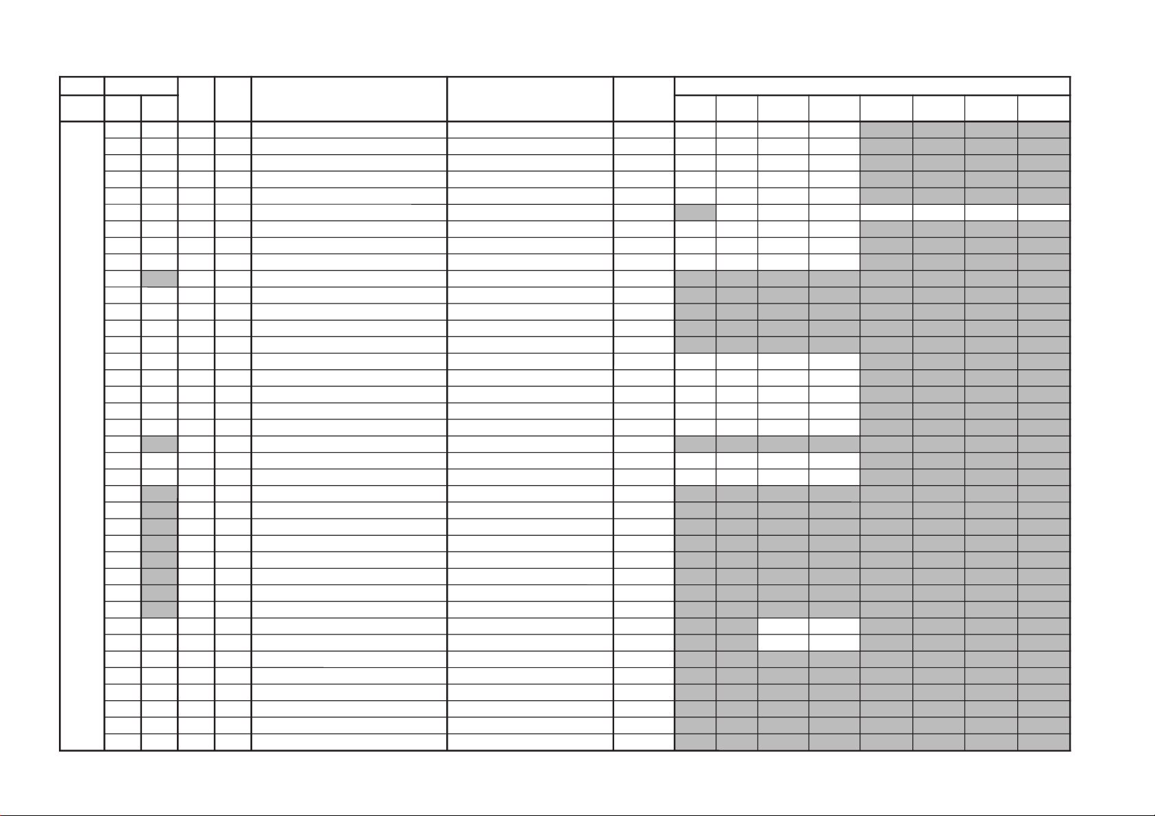
Adjustment Item Table
GVTytilanoitcnuF
laitinIegnaRnoitcnuFetoN&elbaTemaNeciveD
)deliated(eulaVlaitinI
yrogetaCoNemaN CN05CN06CV05CV06
05GORP
CN
06GORP
CN
05GORP
CV
06GORP
CV
OEG00ZSV12F3eziSVCN/CV*06/05QA0512AXCF122F122
10SPV72F3noitisopVCN/CV*06/05F1D1F1D1
20NLV5F0ytiraeniLVCN/CV*06/0570707070
30OCSA0F0noitcerroCSCN/CV*06/0590909090
40ZSHE1F3eziSHCN/CV*06/05D191F191
50SPHF2F3noitisoPH CN/CV*06gorPDVD/05gorPDVD/06/05
A11171F021A021A0
60PAP82F3pmAniPCN/CV*06/05516181A1
70NPU52F3niPrenroCreppUCN/CV*06/055272A203
80NPL32F3niPrenroCrewoLCN/CV*06/0562625292
90
GCU03 tnemtsujdAniPrenroCreppUtsoMCN/CV*06/05
10
10
20
20
A0GCL13 tnemtsujdAniPrenroCrewoLtsoMCN/CV*06/05
10
10
20
10
B0PCU23 gnitteSnoitisoPnoitcerroCniPrenroCreppUtsoMCN/CV*06/05
20
10
10
10
C0PCL23 gnitteSnoitisoPnoitcerroCniPrenroCrewoLtsoMCN/CV*06/05
20
20
10
10
D0LOP01 ytiraloPniPrewoL/reppUtsoMCN/CV*06/05
00
00
00
00
E0HPP42F3tnemtsujdAdiozeparTVCN/CV*06/05*RP/4R/FF52529292
F0LGAA0F0elgnACFACN/CV*06/059191A1A1
01WOB6F0woBCFACN/CV*06/05E1D112E1
11RTHF0F1lortnoCniaGleveLwaSevaWOwaSVCN/CV*06/05*RP/4R/FF80808080
21DPM4F0lortnoCsaiBCDevaWaraPPMCN/CV*06/05*RP/4R/FF70707070
31
APME0F0lortnoCniaGevaWaraPPMCN/CV*06/05*RP/4R/FF
60
60
60
60
41PBPF1F3lortnoCniaGleveLwaSevaWaraPtneCHCN/CV*06/05*RP/4R/FF72927292
51ABPF0F1lortnoCniaGevaWaraPtneCHCN/CV*06/05*RP/4R/FF01E00111
61
SBH11 WSFFO/NOklBHCN/CV*06/05*RP/4R/FF
10
10
10
10
71
LBH73F3lortnoCnoitisoPklBHtfeL CN/CV*06gorPDVD/05gorPDVD/06/05
71
32
71
32
C1
72 C1
72
81
RBHC2F3lortnoCnoitisoPklBHthgiR CN/CV*06gorPDVD/05gorPDVD/06/05
42
62
42
62 92 B2
92 B2
91
PCP07 gnitteSnoitcerroCnoitrotsiDVHpmAniPCN/CV*06/05*RP/4R/FF
00
00
00
00
A1
PCA17 gnitteSnoitcerroCnoitrotsiDVHnoitisoPHCN/CV*06/05*RP/4R/FF
00
00
00
00
B1
PCV83 gnitteSnoitcerroCnoitrotsiDVHlacitreVCN/CV*06/05
C0
C0
C0
C0
C1
PCH23 gnitteSnoitcerroCnoitrotsiDVHeziSHCN/CV*06/05
A0
A0
A0
A0
D1
CSU01 FFO/NOedoMpmuJesluPfeRCN/CV*06/05*RP/4R/FF
00
00
10
10
E1SAVF2F3lortnoCtcepsAVCN/CV*06/05
F2
F22313
F1CSVF1F3lortnoCllorcSVCN/CV*06/05
F1
F1E1E1
02UBV71 lortnoCnoitisoPpoTklBVCN/CV*06/05*RP/4R/FF
40
90
E0
C0
12LBV71 lortnoCnoitisoPmottoBklBVCN/CV*06/05*RP/4R/FF
00
90
C0 F0
22BKAF0F1gnitteSgnimiTesluPfeRhcBBKACN/CV*06/05
C1
F0
C1 71
32SDV11 wSFFO/NOpmuJesluPFERhcBCN/CV*06/05*RP/4R/FF
00
00
00
00
42TSR01 gnitteSnoitisoPtratSevirDVfOecarteRCN/CV*06/05*RP/4R/FF
00
00
00
00
52YPC01 aeraMVNzH06/05llaotatadOEGehtypoC
KV-DR29M67/DR29M87/DR29M97
– 18 –
RM-991
– 19 –
GVTytilanoitcnuF
laitinIegnaRnoitcnuFetoN&elbaTemaNeciveD
)deliated(eulaVlaitinI
yrogetaCoNemaN nommoC0506CNnOocECNffOocECVnOocECVffOocE
CAD00TCH33F7retneCHzH06/055781AXC
0404
10NLH72F3ytiraeniLHzH06/05
0202
20
HDQF1F3esahPFDzH06/05
38
38
30
STHBBFFgnitteSataDtratSdiozeparTHelbaton9C
40
OTHE0FFgnitteSataDtesffOdiozeparTHelbatonE0
50
SSNF7FFataDtratSSNelbatonE7
60
OSN90FFataDtesffOSNelbaton90
70
CBA0FFlortnoCA/DLBACN/CV*ffo/noOCE
00000000
80YPC01 aeraMVNzH06/05llaotatadCADehtypoC
GVTytilanoitcnuF
laitinIegnaRnoitcnuFetoN&elbaT
emaNeciveDnommoC
nommoCoNemaN
BHW00
SOY7F0langisYrofrellecnaCtesffOCD QA0512AXC70
10
SOUF1F31bCrofrellecnaCtesffOCD F1
20
SOVF1F31rCrofrellecnaCtesffOCD F1
30RBSF1F3lortnoCssenthgirBbuS F1
40
RDR92F3evirDR 92
50RDG42F3evirDG 42
60RDB52F3evirDB 52
70
TCR92F3ffotuCR 92
80TCG01F3ffotuCG 01
90TCB52F3ffotuCB 52
A0
OBS02F3tesffOssethgirBbuS cimanyDtpecxeedoMerutciP02
B0
ODRF1F3tesffOevirDR cimanyDtpecxeedoMerutciPF1
C0
ODG91F3tesffOevirDG cimanyDtpecxeedoMerutciP91
D0
ODBB1F3tesffOevirDB cimanyDtpecxeedoMerutciPB1
E0
OCRF1F3tesffOffotuCR cimanyDtpecxeedoMerutciPF1
F0
OCG92F3tesffOffotuCG cimanyDtpecxeedoMerutciP92
01
OCBA1F3tesffOffotuCB cimanyDtpecxeedoMerutciPA1
KV-DR29M67/DR29M87/DR29M97
RM-991
KV-DR29M67/DR29M87/DR29M97
GVTytilanoitcnuF
laitinIegnaRnoitcnuFetoN&elbaTemaNeciveD
)deliated(eulaVlaitinI
yrogetaCoNemaN CNnOocECNffOocECVnOocECVffOocE0506cimanyD
-dradnatS
amarD/
-/eniF-iH
tfoS
lanosreP
JAS00
CIPF3F3lortnoCerutciP lanosrePtpecxeedoMerutciPQA0512AXC
F33382
10
TRBF1F3lortnoCssenthgirB lanosrePtpecxeedoMerutciP
32F1B1
20
LOC72F3lortnoCroloC lanosrePtpecxeedoMerutciP
E2F1F1
30
EUHF1F3lortnoCeuH lanosrePtpecxeedoMerutciP
F1F1F1
40
PHS42F3lortnoCssenprahS lanosrePtpecxeedoMerutciP
22F1D1
50
LMV33 leveLMVedoMerutciP
30301030
60
CYD11 ffo/noroloCcimanyDedoMerutciP
10100010
70
SBW00 hctiwSBWedoMerutciP
00000000
80
XAC23 noitacificepSxirtaMroloCzH06/05
1030
90
AMG33 noitcerroCammaGedoMerutciP
20200010
A0
TCD13 lortnoCnoissimsnarTCDedoMerutciP
20201020
B0
LPD13 lortnoCleveLlatsedePotuAedoMerutciP
20200020
C0
MBA03 lortnoCedoMLBAedoMerutciP
10000000
D0
TBA03 lortnoChtVnoitcetedtnerruCLBACN/CV*ffo/noOCE5000C070
GVTytilanoitcnuF
laitinIegnaRnoitcnuFetoN&elbaTemaNeciveD
)deliated(eulaVlaitinI
yrogetaCoNemaN nommoCCNnOocECNffOocECVnOocECVffOocEVT05oediV05DVD05VT06oediV06DVD06
-RPDVD
05GO
-RPDVD
06GO
JASEO
OLC9F0tesffOroloC 06/05gorPDVD/oediV/VT*06/05QA0512AXC
6080
9090
4040
FO
WLC37 N/SfoegnahCehtothtdiWpetSroloC 30
01
OUH9F0tesffOeuH 06/05gorPDVD/oediV/VT*06/05
5030
7060
4050
11
OHS7F1tesffOssenprahS 06/05gorPDVD/oediV/VT*06/05
01416021F060A1A1
21
WHS17 N/SfoegnahCehtothtdiWpetSssenprahS 10
31
ORB7F0tesffOssenthgirB
CN/CV*ffo/noOCE
70707070
GVTytilanoitcnuF
laitinIegnaRnoitcnuFetoN&elbaTemaNeciveD
)deliated(eulaVlaitinI
yrogetaCoNemaN nommoC
DVD
GORP
CN05CN06CV05CV06
001CRD
CN
001CRD
CV
021CRD
CN
021CRD
CV
LGJ00
NOP11 ffO/nOtuptuOesluPecnerefeRBKAdnaBGR QA0512AXC10
10
BGR77 noitceleStuptuOBGR 70
20
GGA03 noitceleSedoMgnigA 00
30
TBB33 lortnoCrettimiLmottoBBGR 30
40
LML03 lortnoCrettimiLedutilpmABGR 00
50
BAPF0F0LBAkaeProfleveLCD F0
60
BAS03 gnitteSniagLBAS CN/CV*06gorPDVD/05gorPDVD/06/05
0000000000000000
70
OCS7F0lortnoCerutciPbuS 70
80
2VL5F02BGRrofleveLBGR 50
90
LMG01 FFO/NOnoitcerroClaitnereffiDammaG 0000
RM-991
– 20 –
– 21 –
GVTytilanoitcnuF
laitinIegnaRnoitcnuFetoN&elbaTemaNeciveD
)deliated(eulaVlaitinI
yrogetaCoNemaN nommoCVT05oediV05DVD05VT06oediV06DVD06cimanyD
-dradnatS
amarD/
-/eniF-iH
tfoS
lanosreP
LGJAO
SYS23 noitceleSdnaBlangiSDVD/oediV/VT*06/05QA0512AXC
102010202010
BO
0FS11 gnitteS0fssenprahSDVD/oediV/VT*06/05
101010101010
CO
1FS33 lortnoCniaGssenprahS0fhgiHDVD/oediV/VT*06/05
303030303030
DO
SDC03 noitarutaSroloChgiHnilortnoCniaGssenprahS 00
EO
FDC01 FFO/NODCPHS 00
FO
ORP33 lortnoCoitaRtoohS-revO/erPDVD/oediV/VT*06/05
303030303030
01
ITL33 tnemevorpmItneisnarTecnanimuLedoMerutciP
30200000
GVTytilanoitcnuF
laitinIegnaRnoitcnuFetoN&elbaTemaNeciveD
)deliated(eulaVlaitinI
yrogetaCoNemaN nommoC
DVD
GORP
cimanyD
-dradnatS
amarD/
-/eniF-iH
tfoS
lanosreP
anyD
wsb
LGJ11
MTL03 gnitteSedoMITL QA0512AXC00
21
ITC03 tnemevorpmItneisnarTecnanimorhCedoMerutciP
00000000
31
MTC03 gnitteSedoMITC 00
41
LDV33 lortnoCesahPTUOMV 30
51
RCV03 gnitteSleveLgniroCTUOMV 00
61
OFV03 gnitteS0FTUOMV 00
71
MLV03 gnitteSleveLretimiLTUOMV 00
81
CFA13 lortnoCniaGpooLCFA evissergorPDVD/nommoC2010
GVTytilanoitcnuF
laitinIegnaRnoitcnuFetoN&elbaTemaNeciveD
)deliated(eulaVlaitinI
yrogetaCoNemaN nommoCVToediV
CRD00
DOM03
)ylnOnoitaulavEroF(edoMCRD
,i0521decroF-10,lamroN-00
evissergorPelpmiSdecroF-30,evissergorPdecroF-20
KV-DR29M67/DR29M87/DR29M97
RM-991
KV-DR29M67/DR29M87/DR29M97
GVTytilanoitcnuF
laitinIegnaRnoitcnuFetoN&elbaTemaNeciveD
)deliated(eulaVlaitinI
yrogetaCoNemaN nommoCVToediV
PIP00
ORP01 elbanEedoMnacSevissergorPX9849ADS00
10
DER01 edoMelbuoDdaeR 00
20
IEF03 tceleSdleiF 00
30SPH33FFnoitisoPerutciPlatnoziroH 33
40SPVB1FFnoitisoPerutciPlacitreV B1
50
PFH8F0gninoitisoPeniFlatnoziroH 80
60
PFV0F0gninoitisoPeniFlacitreV 00
70
SID03 dradnatSyalpsiD 00
80
SOH03 eziSlatnoziroH 00
90
SEV03 eziSlacitreV 00
A0
SPF03 dradnatStneraPecroF 00
B0
MZH07 mooZlatnoziroH 00
C0
PSV11 noitcudeResioNesluPcnySlacitreV 10
D0
LDV0F1yaleDesluPcnySlacitreV 00
E0
HRF57 latnoziroHhtdiWemarF 50
F0
VWF23 lacitreVhtdiWemarF 20
01
DRV01 noitcudeR 00
11
KBV01 gniknalBlacitreV 00
21
YLD1F yaleDtceleS 10
31
RCP01 noitcerroCnoitisoP 00
41
MGA33 edoMCGA 30
51
CGA9F eulaVlortnoCniaGcitamotuA 90
61
BVC03 tceleSSBVC 00
71
DPC13 noitaruDGNIPMALC 10
81
TPC13 tratSesluPGNIPMALC 10
91
MUL03 tesffOecnanimuL 00
A1
LLP03 tnatsnocemiTLLPtresnIoediV/VT
0000
B1
DCY8F yaleDC/Y 80
C1
RSN03 llPtesnirofnoitcudeReisoNoediV/VT
2000
D1
PSL01 deepSnoitacifitnedIdradnatS 00
E1
LIK23 dlohserTrelliKroloC 20
F1
PGB11 noitisoPetaGtsruB 10
– 22 –
RM-991
GVTytilanoitcnuF
laitinIegnaRnoitcnuFetoN&elbaTemaNeciveD
)deliated(eulaVlaitinI
yrogetaCoNemaN nommoCVToediV
PIP02
CES11 levelnoitacifitnedIMACES 10
12
MED13 noitceleSesahpmeeD 10
22
AMC03 htiwdnaBamorhC 00
32
CFI23 retliFnoitasnepmoCFI 20
42
EUH0F1euH 20
52
ACS6F1tnemtsujdAreirracbuSroloC 60
62
NOC0F tnemtsujdAtsartnoC 00
72
RLB0F lennahCdeRleveLgniknalB 00
82
TRB0F tnemtsujdAssenthgirB 30
92
GLB0F lennahCneerGleveLgniknalB 00
A2
RIB01 lennahCdeRnoisrevnIgniknalB 00
B2
BIB01 lennahCeulBnoisrevnIgniknalB 00
C2
BLB0F lennahCeulBleveLgniknalB 00
D2
TNI01 llavretnIhserfeR 00
E2
RKP58FFlennahCdeRleveLkaeP 58
F2
GKP58FFlennahCneerGleveLkaeP 58
03
BKP58FFlennahCeulBleveLkaeP 58
13
YRF9F YroloCemarF 90
23
TUO11 tamroFtuptuO 10
33
URF0F UroloCemarF 00
43
VRF0F VroloCemarF 00
53
TAS7F tnemtsujdAnoitarutaSroloC 70
63
KPY37 tnemtsujdAkaePY 30
73
OCY0F elbanEgniroCY 00
83LAP33 leveLDILAP 30
93VOP07 lacitreVtesffOnoitisoP 00
A3HOP0F1latnoziroHtesffOnoitisoP 00
B3
HSV0F1knirhSlacitreV 00
C3
HSH0F1knirhSH 00
D3
LPC13 htgneLesluPGNIPMALC 10
– 23 –
KV-DR29M67/DR29M87/DR29M97
RM-991
KV-DR29M67/DR29M87/DR29M97
GVTytilanoitcnuF
laitinIegnaRnoitcnuFetoN&elbaTemaNeciveD
)deliated(eulaVlaitinI
yrogetaCoNemaN nommoCVToediVVT05oediV05DVD05VT06oediV06DVD06
TCY00TNT02F3CSTNroftnemtsujdAtniToediV/VTQA3612AXC
F1F1
10
GNP11 htdiWetaGCSTN/LAP 10
20
INP01 WSytivitisneSCSTN/LAP 00
30LCS5F0lortnoCroloCbuSoediV/VT*06/05
5060
5060
40TCS7F0lortnoCtsartnoCbuSoediV/VT*06/05
7070
7070
50
0FS23 gnignahCycneuqreFretneCssenprahS 20
60
QES33 citsiretcarahCrezilauqEssenprahS 30
70
GHS7F0lortnoCniaGssenprahSDVD/oediV/VT*06/05
607060608060
80
LOYF1F3lortnoCleveLtuptuO-Y E1
90
PSB03 gnignahCtnioPtratShctertSkcalB 00
A0
LOC01F3lortnoCleveLtuptuOrC/bC 31
B0
RCD03 tnemtsujdAoitaRnoitarotseRCD 00
C0
0FB13 tnemtsujdA0FFQT/FPB 10
D0
QFB23 tnemtsujdAQFQT/FPB 20
E0
WSF11 hctiwSFQT/FPB 10
F0
TDS11 hctiwSparTelbuoDMACES 10
01
FPL11 hctiwSFPLrC/bC/Y 10
GVTytilanoitcnuF
laitinIegnaRnoitcnuFetoN&elbaTemaNeciveD
)deliated(eulaVlaitinI
yrogetaCoNemaN nommoC
itluM
bmoC
bmoCD3tupnI-SsrehtOoediVDVD
TCY11
LDY6F0tnemtsujdAemiTLD-Y srehto/tupni-S/bmocD3/bmocD2
60606060
21
1OB7F0)etuorniam(tnemtsujdA1tesffObC 70
31
1OR7F0tnemtsujdA1tesffOrC 70
41
FDC07 hctiwSycneuqerFnwoDtnuoCVlangisonrofzH05decrof00
51
MDC03 hctiwSegduJnwoDtnuoCV 00
61
CFA03 hctiwSytivitisneSCFADVD/oediV)/VT(
0000
71
MVM11 ksaMCFA+ksaMnoisivorcaM 10
81
YRS7F0tnemtsujdAkcalBY-RMACES 70
91
YBS1F0tnemtsujdAkcalBY-BMACES 10
A1
LEB23 gnihctiwSFPH/LLEBMACES 20
B1
FLB01 tnemtsujdA0fLLEB 00
C1
IVS01 hctiwSDI-VMACES 00
D1
PGS03 tnemtsujdAnoitisoPetaGMACES 00
E1
DIS11 hctiwSytivitisneSMACESMACEStpecxe10
F1
HIS01 hctiwSnoitibihnIMACES 00
02
PTS01 sulPLAProfputeSleveLkcalBY 00
12
RN311 ffO/nOnoitarepORND3 10
22
6WB11 ffO/nOlangiStsuB-noNzH06rofRND3 10
32
HSW03 noitcudeResioNrofpetSniaGssenprahS 00
42
OCW03
esioNrofpetSleveLtuptuOrC/bC
noitcudeR
00
RM-991
– 24 –
– 25 –
GVTytilanoitcnuF
laitinIegnaRnoitcnuFetoN&elbaTemaNeciveD
nommoC
yrogetaCoNemaN
NYS00
TAM13 noisrevnoCxirtaMfoepyTtceleS 1512AXC00
10
RFV11 tuptuOcnySymmuDfoycneuqerFtceleS 10
20
CTV33 tnatsnoCemiTnoitarapeScnySVehtsteS 30
30
DWH03 htdiWesluPtuptuOTUO_HLESehtsteS 00
40
LSH01 dohteMnoitarapeScnySehtsteS 00
50
CTH01 tupniNIGYfotnatsnoCemiTnoitarapeScnySHehtsteS 00
60
AMH11 TUOHLEStacnysVnihtiWcnysHddaottonrorehtehWsteS 10
70
CAM11 langiSP525ehtfolangisnoisivorcaMehtgnitanimilErofhctiwS 10
80
LSG13 TUORCLESottuptuOlangiSehtfoetuMroniaGehtstceleS 10
90
GBC7F0lortnoCniaGTUOBCLES 70
A0
GRC7F0lortnoCniaGTUORCLES 70
B0
GY7F0lortnoCniaGTUOYLES 70
C0
RFH13 TUOHLESottuptuOcnySymmuDehtfoycneuqerFehttceleS 10
GVTytilanoitcnuF
laitinIegnaRnoitcnuFetoN&elbaTemaNeciveD
)deliated(eulaVlaitinI
yrogetaCoNemaN nommoCcimanyD
-/dradnatS
amarD
-/eniF-iH
tfoS
wsbanyDwsbamarDwsbtfoS
2PA00
SBB3F0gnitteStsooBssaB 9311WJN30
10
BCB01 ssaB-buStuC/tsooB 00
20
SBS03 gnitteSssaB-buS 00
30
TCB01 elberT-buStuC/tsooB 00
40
STS03 gnitteSelberT-buS 00
50
LGA03 gnitteSleveLCGA 00
60
WSB01 hctiwStsooBssaB 00
70
SAB41F1lortnoCedomdnuoSssaB FFO/NOSBBhtiwlanosreptubedoM.S
410101211010
80
ERT61F1lortnoCedomdnuoSelberT FFO/NOSBBhtiwlanosreptubedoM.S
616101616101
90
EBB84FFlortnoCedomdnuoSEBB FFO/NOSBBhtiwlanosreptubedoM.S
749300749300
KV-DR29M67/DR29M87/DR29M97
RM-991
KV-DR29M67/DR29M87/DR29M97
GVTytilanoitcnuF
laitinIegnaRnoitcnuFetoN&elbaTemaNeciveD
nommoC
yrogetaCoNemaN
PSM00
TSW51FFdlohserhToeretSG/W D5143PSM51
10
TBWCEFFdlohserhTlaugniliBG/W CE
20
LLW5FFdlohserhTlaruanoMG/W 50
30
CAW1F0tnuoCtnemeergAG/W 10
40
LDW03FFyaleDhcraeSG/W 03
50
LDN02FFyaleDhcraeSMACIN 02
60
LDS01FFyaleDdaeRsutatSoeretS 01
70
CGA11 tnatsnoC/otuAhctiwSCGA 10
80
LER82F3edoMtnatsnoCtaniaGCGA 82
90
MRC01 ffO/nOgnituMreirraC 00
A0
OCA11 ffO/nOtuOkcolCoiduA 10
B0
PFB1F7metsySM-noNrofelacserPMF B1
C0
MPF23F7metsysMrofelacserPMF 23
D0
HF63F7VEDHrofelacserpMF 63
E0
MHF56F7MdnaVEDHrofelacserpMF 56
F0
PGWC1F7elacserPG/W C1
01
PINF7F7elacserPMACIN F7
11
RRE05FFdlohserhThctiwSMFotuA 05
RM-991
– 26 –
– 27 –
GVTytilanoitcnuF
laitinIegnaRnoitcnuFetoN&elbaTemaNeciveD
)deliated(eulaVlaitinI
yrogetaCoNemaN nommoCVToediVcimanyD
-dradnatS
amarD/
-/eniF-iH
tfoS
lanosreP
ITLA1
WLN77 reifilpmAytiraeniL-noNfohtdiWpetS 70
B1
DGVF1F3ammaGelbairaVedoMerutciP
F1F1F1F1
C1
WGV07 ammaGelbairaVfohtdiWpetS 00
D1
DKPF3F3edutilpmAgnikaePedoMerutciP
F3B2E0B2
E1
WKP8F0edutilpmAgnikaePfohtdiWpetS 80
F1
DPS0F3noitcerroCssenpeetSedoMerutciP
00000000
02
DRCB1F3leveLgniroCedoMerutciP
B1B100B1
12
WRC9F0leveLgniroCfohtdiWpetS 60
22
ORC6F0edoMoediVroftesffOleveLgniroC 60
32
DWLF1F3noitcerroChtdiWeniL F1
42
MNS07 noitidnoCN/SelbailernUrednUedoMN/S 00
52
CNS3F0retnuoCegarevAoitaRN/SoediV/VT
3030
62
CMF2F0retnuoCgnihctaMedoMerutaeF 20
GVTytilanoitcnuF
laitinIegnaRnoitcnuFetoN&elbaTemaNeciveD
)deliated(eulaVlaitinI
yrogetaCoNemaN nommoCcimanyD
-dradnatS
amarD/
-/eniF-iH
tfoS
lanosreP
ITL00
HDL11 noitceleStnemgesmargotsiH8719ADT10
10
SFC11 noitceleSretliFruotnoC 10
20
BLW01 hctiwSwodniWxobretteL 00
30
CDV11 gniroCtnednepeDoediVedoMerutciP
10101010
40
MED01 edoMnoitartsnomeD 00
50
PDC470yaleDecnanimuL 40
60
PSO01 gnikaePtramSelurrevO 00
70
OPW01 ffOhctertStnioPetihW 00
80
KSD01 hctiwSenoTnikSedoMerutciP
00000000
90
KSA01 noitceleSelgnAenoTnikS 00
A0
KSW01 noitceleShtdiWenoTnikS 00
B0
KSS01 noitceleSeziSenoTnikS 00
C0
RGD11 hctiwStnemecnahnEneerGedoMerutciP
10100010
D0
TGD77 hctiwStnemecnahnEneerGfodlohserhT 70
E0
RGG01 niaGtnemecnahnEneerG 00
F0
RGW01 htdiWtnemecnahnEneerG 00
01
RGS01 eziStnemecnahnEneerG 00
11
LBD01 hctiwShctertSeulB 00
21
LBG01 noitceleSniaGhctertSeulB 00
31
LBS01 noitceleSeziShctertSeulB 00
41
SDC11 ssenprahStnednepeDroloCedoMerutciP
10100010
51
TSC77 ssenprahStnednepeDroloCfodlohserhT 70
61
ITC11 tnemevorpmItneisnarTroloCedoMerutciP
10100000
71
NOB01 noitasnepmoCtesffOkcalBedoMerutciP
00000000
81
DTB0F3htcertSkcalBevitpadAedoMerutciP
00000000
91
DLN51F3reifilpmAytiraeniL-noNedoMerutciP
51510051
KV-DR29M67/DR29M87/DR29M97
RM-991
KV-DR29M67/DR29M87/DR29M97
GVTytilanoitcnuF
laitinIegnaRnoitcnuFetoN&elbaTemaNeciveD
)deliated(eulaVlaitinI
yrogetaCoNemaN nommoCVToediV0edomRN1edomRN2edomRN3edomRNcimanyD
-dradnatS
amarD/
-/eniF-iH
tfoS
lanosreP
MC300
MRN03 edoMnoitarepOnoitcudeResioN 38046DPU00
10
OCYE0F0noitceleStuptuOlangiSC/Y D0
20
CYS13 noitceleSkcolCmetsyS 10
30
DTS03 noitceleSnoitarepOdradnatS-noN/dradnatS 00
40
SSM03 noitceleSnoitarepOeniL-retnI/emarF-retnI 00
50
LIK33 noitceleSnoitarepOrelliK-noN/relliK 30
60
SCE13 noitceleStupnIcnyS-ClanretxE 10
70
PPC23 noitceleShtdiWesluPpmulC&leveLtupnICDA 00
80
PDH57 tnemtsujdAesahPlatnoziroH 50
90
LDC47 tnemtsujdAyaleDlangiS-C 40
A0
CYD2F0tnemtsujdAleveLgniroCnoitceleDYD)3-0(edoMRN
20202040
B0
GYDA0F0tnemtsujAniaGnoitceleDYD)3-0(edoMRN
A0A0A0A0
C0
CCD5F0tnemtsujdAleveLgniroCnoitceteDCD)3-0(edoMRN
50303050
D0
GCD5F0tnemtsujdAniaGnoitceteDCD)3-0(edoMRN
50A0A050
E0
RNY1F0puteSretliFraeniL-noNRNY 10
F0
RNC1F0puteSretliFraeniL-noNRNC 10
01
CSW13 tnemtsujdAgniroCnitceteDesioN 10
11
HTV13 dradnatS-noNcnyS-HrofnoitceleSsiseretsyHoediV/VT
1010
21
RTV13 dradnatS-noNcnyS-HrofnoitceleSytivitisneSoediV/VT
1010
31
RDL23 dradnatS-noNcnyS-emarFrofnoitceleSytivitisneSoediV/VT
2010
41
PAV37 noitcerroCepahSlacitreVroftnemtsujdAniaGedoMerutciP
30000000
51
IAVC0F1noitcerroCepahSlacitreVroftnemtsujdAgnihsinaVedoMerutciP
C0000000
61
FPY33 FPBgnikaeP-YrofnoitceleSycneuqerFretneCedoMerutciP
30303030
71
GPY8F0FPBgnikaeP-YroftnemtsujdAniaGedoMerutciP
80808080
81
ESVA0F0puteSretliFbmoCeniL A0
91
NCC01 hctiwSretliFtilpSlangiS-C 00
A1
SOC01 noitcudeReisoNtahctiwSylaeDlangiS-C 00
B1
CDS01 hctiwSytivitisneSnoitceteDCD 00
C1
YDS11 hctiwSytivitisneSleveL-rewoLnoitceteDYD 10
D1
CHY03 noitceleSgniroCleveL-rehgiHlangiS-YedoMerutciP
00000000
E1
GHY01 hctiwSniaGreveL-rehgiHlangiS-YedoMerutciP
00000000
F1
THS0F0stiBtseTretnuoCV/H&noitceteDdradnatS-noN 00
02
KLC8F0stiBtseTkcolC 80
12
LLPD0F0puteSretliFLLP D0
22
FRK3F0tnemtsujdAecnerefeRnoitceteDrelliK 30
32
LSHC0F0tnemtsujdAleveLecilScnyS-H C0
42
LSV8F0tnemtsujdAleveLecilScnyS-V 80
52
SPB4F0tnemtsujdAnoitisoPtratSetaGtsruBlanretnI 40
62
WPBA0F0tnemtsujdAhtdiWetaGtsruBlanretnI A0
72
CDA33 noitceleSyaleDkcolCCDA 30
82
DPA11 hctiwSnwoD-rewoPCDA 10
92
DPS23 hctiwSnwoD-rewoPyromeM 00
– 28 –
RM-991
– 29 –
GVTytilanoitcnuF
laitinIegnaRnoitcnuFetoN&elbaTemaNeciveD
)deliated(eulaVlaitinI
yrogetaCoNemaN nommoC
DVD
GORP
0506VToediV
MC200
NUF33 noitcnuF N96A09CT30
10
MCY03 rotarapeSC/Y 00
20
RNC03 KRNC 00
30
MIL03 timiLRNC 00
40
FPC01 FPL-C 00
50
PLS01 FPL-CleS 00
60
OFY01 ofP-Y oediV/VT
0000
70
GPY13 niaGQE-Y oediV/VT
2020
80
LPY13 timiLC.N/QE-Y oediV/VT
0000
90
PLC01 pilC.sdP 00
A0
FPY11 FPL-Y oediV/VT
0000
B0
GEV37 niaGhpmE-V 30
C0
NEV37 L.NhpmE-V 30
D0
CEV23 eroChpmE-V 20
KV-DR29M67/DR29M87/DR29M97
RM-991
 Loading...