

Sony KV32FV15, KV36FV15 Service Manual
S®
TM
WEGA
Direct View
Television
AA-2W Chassis
Models: KV27FV15 KV32FV15
KV36FV15 KV32FS10
KV36FS10 KV32XBR250
Training Manual
KV36XBR250
Circuit Description and Troubleshooting
Course: CTV-26

Sony Service Company
A Division of Sony Electronics Inc ©1999
All Rights Reserved
Printed in U.S.A.
S is a trademark of Sony Electronics

Circuit Description
and Troubleshooting:
Model: KV27FV15 KV32FV15
KV32FV15 KV36FV15
KV32FS10 KV36FS10
KV32XBR250
KV36XBR250
Prepared by: National Training Department
Sony Service Company
A Division of Sony Electronics Inc.
Course presented by _____________________________________
Date___________________________________________________
Student Name ___________________________________________

S
SEL Service Company
A Division of Sony Electronics Inc.
1 Sony Drive
Park Ridge, New Jersey 07656
CTV261299
Printed in U.S.A.

Table of Contents
Features 1
Board Descriptions 2
Picture Tube Defect Symptoms 3
V Chip 5
Introduction 5
What is V Chip Technology? 5
Parental Guideline Rating System 5
Parental Control Menu 6
Decoding 6
Power Supply Block 7
Standby Power Supply 9
Converter Operation 9
Regulation 9
Power On/Degaussing 13
Power On 13
Soft Start/Regulation/Foldback 19
Soft Start 19
Regulation 19
Foldback 19
Secondary Voltages 21
+135 Volts 21
+12 Volts 21
+9 Volts 21
+5 Volts 21
Audio B+ 21
Power Supply Protection 25
+135 Over Current Protection 25
Foldback 25
Vertical Deflection 27
Horizontal Deflection Block 31
Degaussing 13
Converter 15
Initial Start Up 15
Soft Start 15
Regulation 15
Troubleshooting 17
Horizontal Out 33
Pincushion 35
H Protect 37
Appendix - Service Bulletins i
1
Features
Introduction
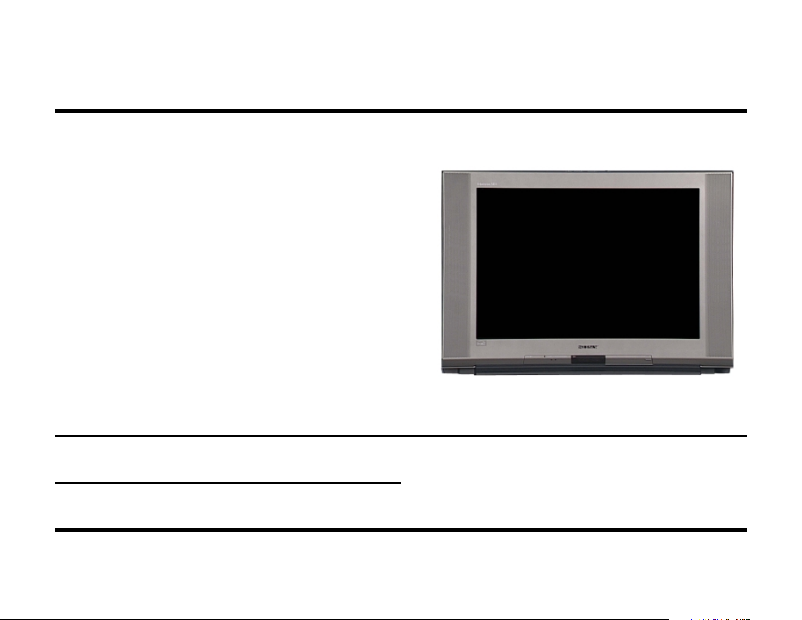
This course covers AA2W chassis Sony direct view televisions. These
sets are part of the WEGA line which contain the flat screen FD Trinitron
picture tubes. This course describes the Power Supply, Deflection and
Protection circuits with a twist of practical troubleshooting tips and known
solutions. In addition, this course reviews picture tube diagnostics and
solutions, plus the latest information on the V-Chip.
The US models listed below use the AA2W chassis design.
KV27FV15 KV36FS10
KV32FV15 KV32XBR250
KV36FV15 KV36XBR250
KV32FS10
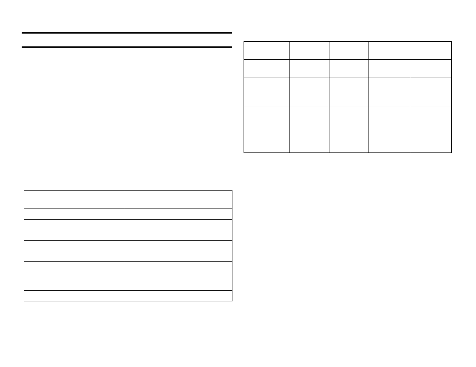
The following is a list of features that all of these models have.
FD Trinitronfi Picture Tube Trinitone Color Temperature
Adjustment
Dynamic Picture Processor Velocity Modulation
Dynamic Focus Circuitry MTS Stereo TV Decoder3
Customer Tilt Correction dbxfi Noise Reduction
The table below shows which features are different between models.
KV27FV15 KV32/36F
V15
Audio
Power
2 Tuner PIP
Component
Video Input
Remote
Infrared
Headphones
Comb Filter
S-Link
*One significant difference between the 27FV15 model and the rest of the
models is the lack of the component input. This model will have a much
simpler video path because of this.
3D Digital Comb Filter analyzes the picture along the three dimensions
of height, width and time, to minimize even subtle picture artifacts.
3-Line Digital Comb Filter analyzes three TV scanning lines at a time for
better color.
Vertical Aperture Compensation sharpens picture definition and edge
detail on the vertical plane producing sharp horizontal edges.
15Wx2 15Wx2 10Wx2 15Wx2
Yes Yes No Yes
N/A* 1 1 1
N/A N/A N/A Yes
3 line 3 line 3 line 3D
Yes Yes No Yes
KV32/36FS10KV32/36XB
R250
Auto Pedestal Clamp DAC Speaker System
Magnetic Quadra Pole Focus SRS 3D Audio Effect
V-Chip Parental Control 1Front/2Rear A/V Inputs
Program Palette Presets CaptionVision (CC)/ XDS (Extended
Data Service)
Vertical Aperture Compensation Steady Sound With BBE
Steady Sound™ Automatic Volume Control with BBE equalizes the
volume levels so there is consistency between programs and commercials.
Auto SRS® Sound Enhancement creates a vivid stereo image using
the principles of human hearing to make the sound appear to come from
widely separated speakers.
Magnetic Quadra Pole reduces beam spot distortion and improves corner-to-corner focus, as well as picture sharpness.
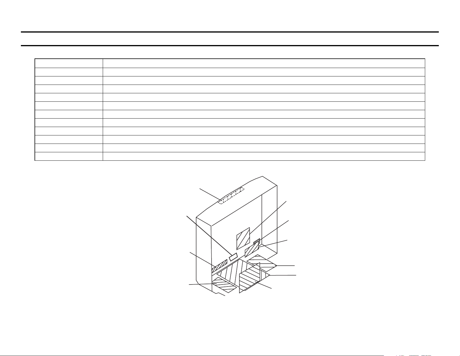
Board Descriptions
y
Name Description
A Micon, Y/C Jungle, Tuner, Pincushion, H Deflection, V Deflection, H Deflection, Syston
AK Audio Amp, Surround Sound, Sub tuner, S-Link
C RGB Drive
G Power Supply
HA Front A/V Inputs, Menu Buttons
HB IR Detector
HX Buttons
T (XBR Only) IR Headphones
UX (XBR Only) 3D Comb Filter, A/V Switch, Audio Control, SRS, Chroma Decode, PIP Encode
UY (All Except XBR) 3 Line Comb Filter, A/V Switch, Audio Control, SRS, Chroma Decode, PIP Encode (except FS10 model)
WA Velocit
Modulation, Quadrapole
HX
C
T
(XBR only)
HB
WA
HA
G
A
AK
UX/UY
XBR/Non-XBR
CIRCUIT BOARDS LOCATION
2
3
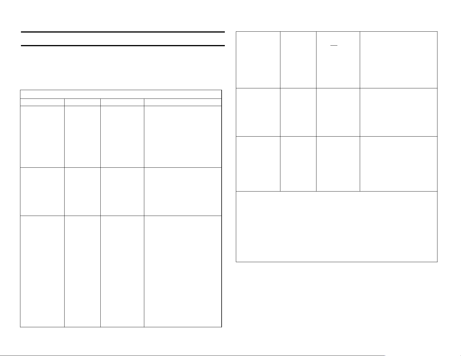
Picture Tube Defect Symptoms
Overview
Below is an excerpt from the CTV-25 course. It shows several picture
tube defect symptoms, some of which can be repaired without changing
the tube.
Defective Picture Tube Symptoms
Symptom Suspect Check Procedure
Dark picture or
one color
missing.
Dark picture Grid 1 to
Bright red,
green or blue
picture.
One color
retrace lines
may be
present.
Retrace lines
are diagonal
lines that run
from lower left
to the upper
right corner.
Heaters
Open
Grid 2
short.
Heater
Cathode
short.
OR
Cathode to
Grid 1
short.
Apply 6Vdc to
the heater
terminals.
Some heaters
are connected
in parallel,
others in
series but all
take 6Vdc.
There should
be infinite
resistance
between the
G1 and G2
pins.
Remove the
R, G or B
video input to
the CRT for
the bright
color. If that
color is still
bright, the
tube is bad.
There should
be infinite
resistance
between any
CRT pin to
either Heater
pin. *
Clean the CRT pins and
examine the socket for
corrosion.
Apply 6Vdc to the CRT
heater pins, looking for a
glow in all three heaters.
Then if a heater(s) does not
glow, replace the picture
tube.
1. Unplug TV and remove
C board.
2. Apply 15-20Vdc
between the G1 and G2
pins to vaporize the
short. Current limit the
power supply to 1 Amp.
Replace tube.
Bright picture
with retrace
lines and/or
poor focus.
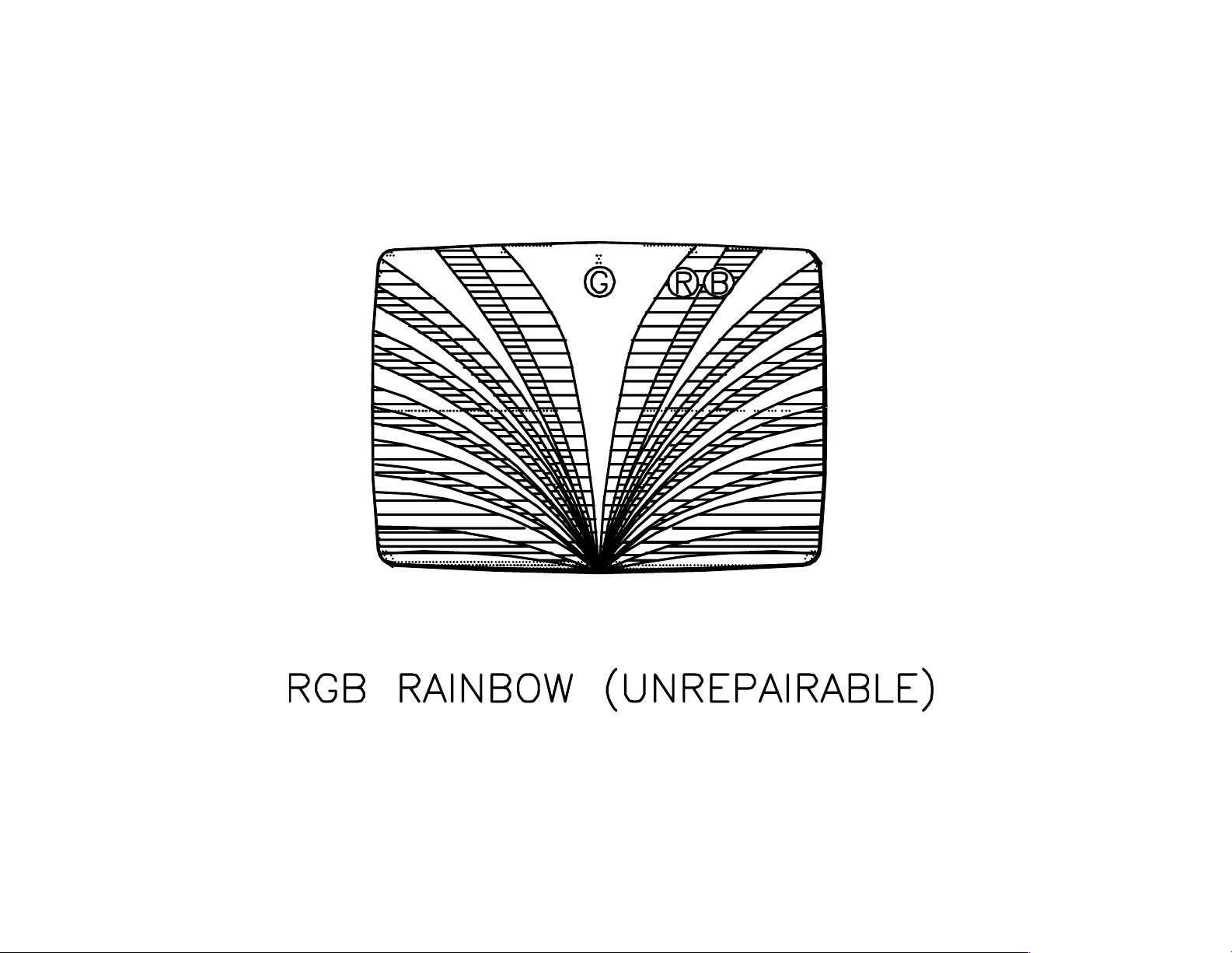
RGB Rainbow.
(see rainbow
picture)
Purity / Beam
landing is off.
* Only the heater pins should have resistance. All other pins have infinite (∞)
resistance to each other and to either heater pins.
Used picture tubes that have a heater-cathode leakage/short have a low
restoration success level.
** Do not manually Degauss. New 27 35 picture tubes are magnetically
conditioned for optimum beam landing. Strong manual degaussing will
destroy this conditioning. Applying disc magnets (P/N = 1-452-094-00) to the
bell of the picture tube is the only way to compensate for lost magnetic
conditioning. The Sony manual degaussing tool can be used to degauss
these tubes because of its reduced field intensity (P/N = 7-700-781-01).
Grid 2 to
high
voltage
Grid 3
leakage.
Aperture
grill was
unseated in
transit.
The TV s
degaussing
circuit did
not
demagnetiz
e aperture
grill metal
support.
Symptom is
that all three
colors are
bright.
Rainbow of
colors can
start at the top
or bottom
(bottom
rainbow
shown).
Same color
blotches
remain at that
area of the
screen
regardless of
picture screen
changes.
Reduce G2 / screen voltage
to the lowest setting.
Vary focus control to both
limits several times.
Put on safety apparel.
Place the tube face down
and lightly tap the neck to
dislodge the particle.
A loose aperture grill is
dangerous and may cause
tube implosion. Use
safety precautions. Do not
jar set. Transport TV face
down.
Do not manually Degauss
the picture tube with a
strong degaussing coil **.
Repair the TV s degaussing
circuit. The thermistor or
cold solder is usually at
fault.
all
4
5
V Chip
Introduction
“Pursuant to the Commission’s rules, half of all new television models 13
inches or larger manufactured after July 1, 1999, and all sets 13 inches or
larger manufactured after January 1, 2000 must have V-Chip technology.
Set top boxes that allow consumers to use V-Chip technology on their
existing sets are now available.” This quote from the FCC web page
defines the guidelines that manufacturers of television receivers must follow. No matter what your personal feelings on the ratings issue, you will
be forced to deal with it as a technician. Here you will be given information on what V chip technology is, how it is implemented in Sony televisions and what to do if the customer forgets their password.
Broadcasters are not required at this time to transmit ratings for their programming. At this time, however, the major networks are broadcasting
ratings but all of their affiliates are not. In addition, many of the popular
cable stations are broadcasting V Chip ratings.
What is V Chip Technology?
The V Chip system allows broadcasters to send data that contains ratings. The television receiver processes this data and acts according to
the programming wishes of the user. The user’s television has menu
options for determining which programs should be blocked. These options are compared to the data received and programs are blocked accordingly.
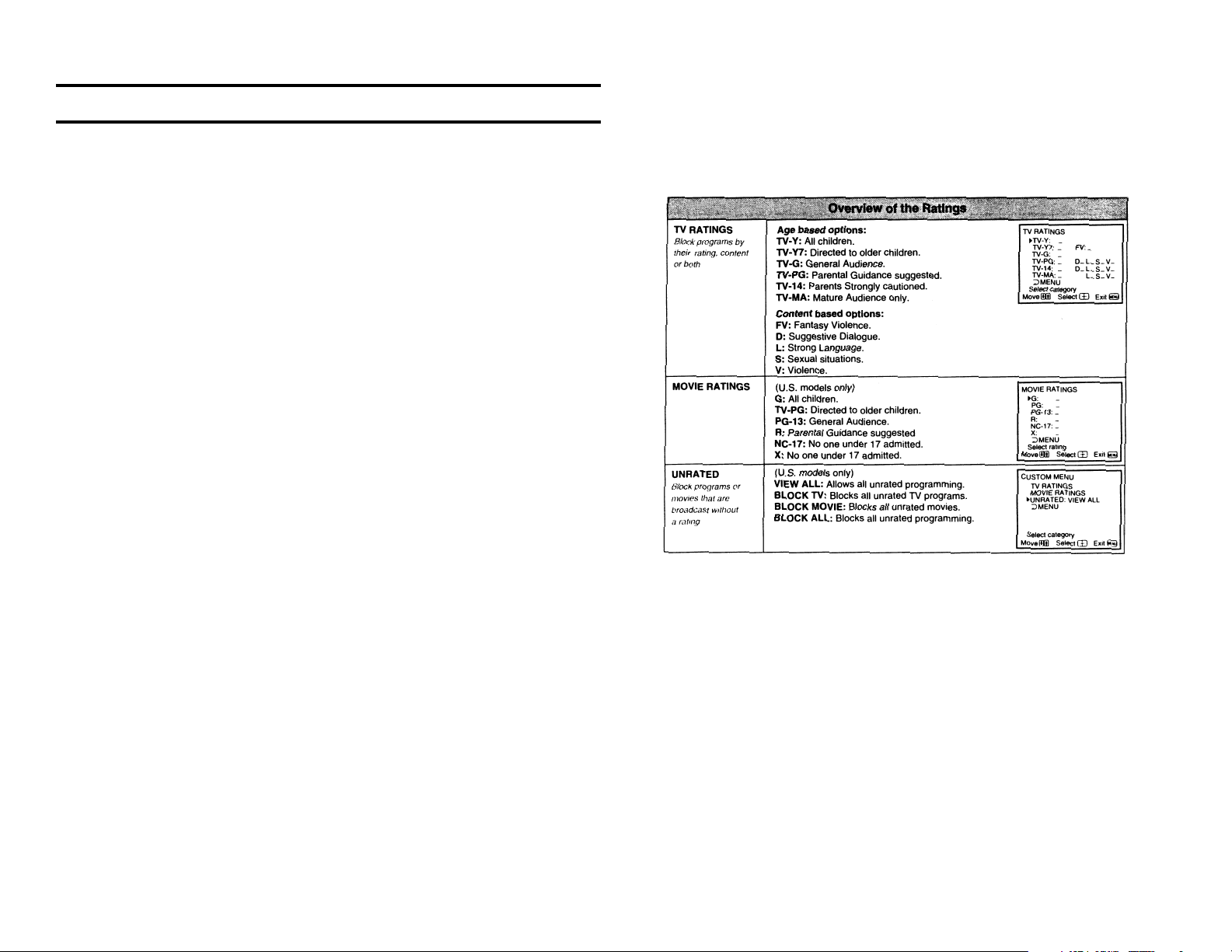
Parental Guideline Rating System
The ratings can be separated into three categories. They are TV Ratings,
Movie Ratings and Unrated. The following table shows the ratings for the
three categories.
The TV Ratings are both age and content based. The level of the content
rating is also based on age. For example, a program with a TV-PG V
(Violence) rating may contain moderate violence, while a TV-14 V rating
may contain more intense violence.
The consumer may choose to block Unrated programs. If they do this,
they need to be aware that emergency broadcasts, political programs,
sports, news, public service announcements, religious programs and
weather programs may be blocked.
Parental Control Menu
Sony V Chip equipped televisions contain the Parental Control Menu,
which is located in the Setup section. When it is selected, the user will be
asked for a 4-digit password. After this password is entered, the user will
be asked to confirm it. After confirmation, the password is set. Anytime
the user wants to modify the Parental Control Menu, the password must
be entered. Note: If the customer forgets their password, the master
Password 4357 can be entered. This allows the customer to reset
their password. No settings can be changed until a new password
is entered.
When you have entered the password, an options menu will be displayed.
The options are as follows.
Parental Lock: This is used to enable or disable the ratings system. This
is done by selecting On or Off.
Here the user can select ratings by age or content. If they do not want
violence of any kind to be seen but are not offended by strong language,
they can select the V for PG-14. This will block all V settings above PG-
14.
Decoding
The Parental Guideline Rating that is broadcast by the programmer must
be decoded at the receiver. This rating data is placed on Line 21 Field 2
or Line 284.
Rating: There are four ratings that can be selected.
Child – The child selection is used to enable only TV-Y, TV-Y7, TV-G
and G ratings.
Youth – The youth selection is used to enable TV-PG and PG ratings.
Ratings considered lower than these will also be enabled.
Youth Adult –Tthe youth adult selection enables TV-14 and PG-13
ratings in addition to lower ratings.
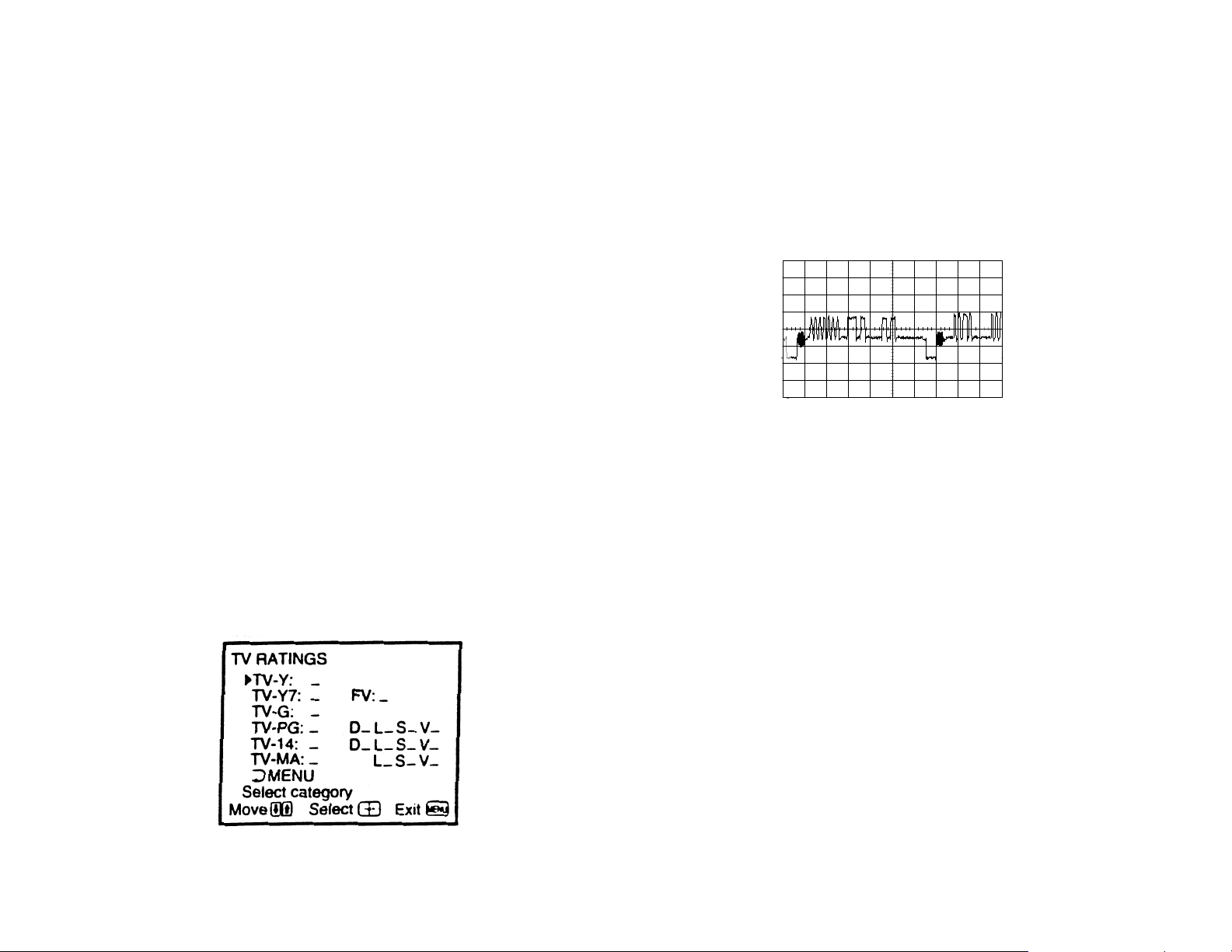
Custom – The custom selection allows you to tailor the age and con-
tent ratings to your liking. The picture below shows the menu that will
be seen when custom is selected.
The preceding waveform shows the contents of Line 21 Field 2. We see
that right after the burst signal on the back porch of the horizontal sync is
a clock signal. This clock is used to inform the decoder that data is coming and to synchronize the decoder and data. Since there is other XDS
(Extended Data Services) data on this line, the first three data bits are
known as the identifier. Data 001 identifies the data as Parental Ratings
data. Then two bytes of data are sent which contain the rating information. The first byte contains information about the age rating and the
second contains information about the content rating.
Ratings are decoded by the System Control IC in Sony televisions. These
ICs contain the programmed information and the decoder. When a program is determined to have a rating that should be blocked, this is recognized. The System Control IC also contains the OSD outputs. When the
program is to be blocked, the OSD section outputs a black screen along
with the blocked show’s rating. For example, if the Parental Controls are
set to Child and the received program is rated TV-14, the screen will be
black with TV Rating TV 14 in white letters.
There is also an additional V-Chip IC used on sub-tuner video. This prevents blocked programs from being displayed in the PIP window.
6

7
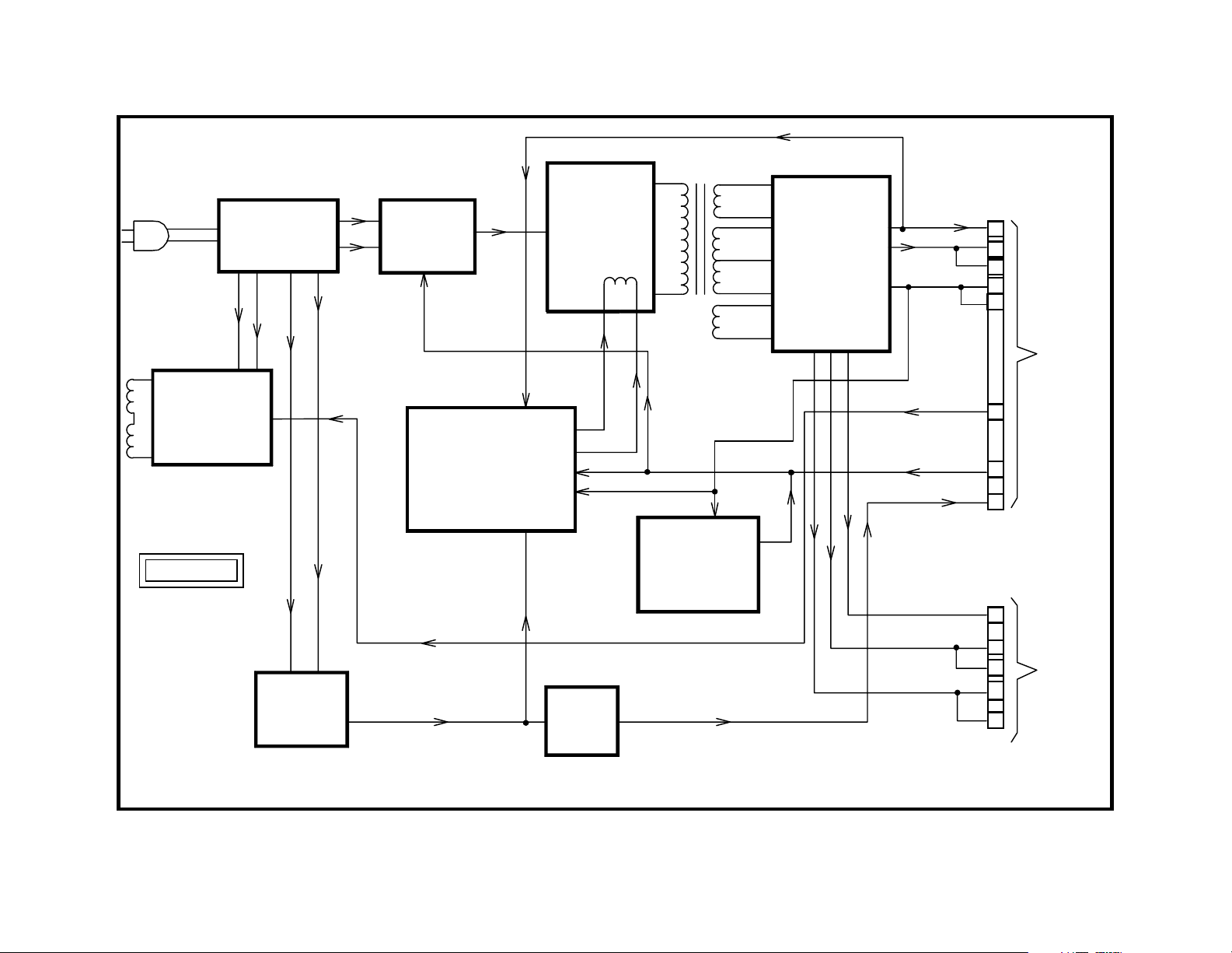
Power Supply Block
Overview
The power supply in the AA2W chassis is located on the G board. AC
from the outlet is applied to a series of line filters and protection devices
and eventually applied to the standby supply, AC rectifier and degauss
circuits. The Standby supply is a switching supply whose output is applied to a 5-volt regulator. The output from the regulator exits the G board
at CN641/10. It is applied to various components in the set that need to
be powered when the set is OFF. These include the Micon and the remote sensor.
When the set is turned ON by using either the power button or the remote
control, 5 volts is applied to CN641/11. This 5 volts is used to turn RY600
Power Relay ON. When the relay closes, a click is heard. Closing the
relay allows the rectified ac voltage to be applied to the converter circuit.
The converter begins operation when this voltage is applied. The power
ON line is also applied to the soft start circuit. The soft start circuit holds
the B+ voltage low while the power supply filters charge by controlling the
voltage present across the control winding. The control winding determines the switching frequency of the converter. After soft start operation
is complete, the regulation circuit takes over operation of the control winding. This allows the converter’s output to be coupled through T605 to the
secondary supplies. These supplies supply power to the rest of the set.
The regulation circuit monitors the +135 volt line.
Shortly after the click of the power relay at turn ON, another click is heard.
This click is RY601 Degauss Relay closing. This may be accompanied by
a hum sound that indicates the operation of the degaussing coils. After
the AKB circuit operation is considered normal, the degaussing relay opens.
This is the third click that occurs about 8-10 seconds after the unit is
turned ON.
During operation of the set, the +135 volt line is monitored for DC protection. This protection circuit is used in conjunction with the latch to switch
the Power ON line LOW if a failure should occur. This will turn RY600
Power Relay OFF and turn the power supply OFF. In addition to this
protection circuit a foldback circuit can also shut down the power supply.
The foldback circuit compares the secondary’s +12 volt output to a voltage on the primary side. If there is a problem with either one of these
circuits, the set will shut down.
T605
DEGAUSSING
RY601
DGC
G BOARD
+
AC
INPUT
STANDBY
POWER
SUPPLY
AC
RECT. +
RY600
SOFT START
FOLDBACK
REGULATION
CONVERTER
5V
REG
+135V
DC
PROTECTION
& LATCH
SECONDARY
SUPPLIES
12V
9V
B+ 135V
DGC
POWER ON
STANDBY 5V
CN642
5V
AUDIO B+
AUDIO GND
12
11
10
8
6
7
1
2
TO
CN1641
A BOARD
CN641
5
1
2
3
4
TO
CN1643
AK
BOARD
POWER SUPPLY BLOCK
8
7CTV26
1/1/00
9
Standby Power Supply
Overview
The standby power supply is a switching power supply used to create
Standby 5V. The Standby 5V line is used to power the Tuning Micon and
EEPROM and any other circuits which need power when the set is OFF.
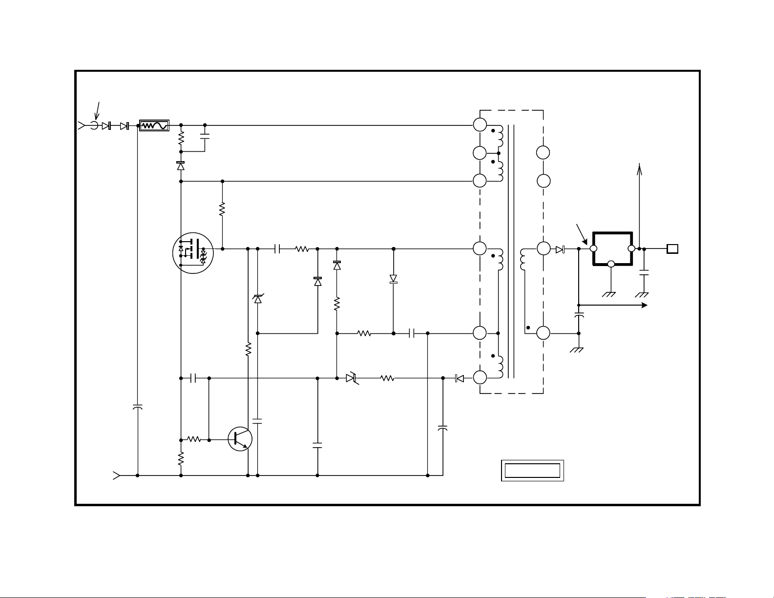
Converter Operation
Operation of the Standby power supply begins when the set is plugged in.
The AC line voltage is applied across the standby power supply. The AC
low side is ground for this circuit. The AC high side is applied to a half
wave rectifier consisting of D621 and D622. Two diodes are used so that
there will be protection should one of them fail. This voltage is then applied to T621/1 SRT Input through R639. R639 is a fusible resistor used
for current limiting and failure protection. It will open if the standby switching circuit draws excessive current. Please note that the board has T621
SBT silk-screened on it. This differs from the service manual, which calls
T621 SRT.
When the voltage is applied to T621/1 SRT Input, current flows through
the winding and R631 to Q621/G. Q621 Converter is a FET with added
protection. When a positive voltage is applied to the gate, it begins to
conduct drain to source. This reduces the voltage at T621/3 to close to
zero. Normally this would reduce the voltage at Q621/G, but a voltage is
supplied to the gate through R632 and C630 from T621/4. This voltage is
induced into the secondary winding of T621/4 when current flows through
the winding between T621/1 and T621/3. The voltage is not permanent
due to C630. As C630 charges, it reduces the voltage at Q621/G. Once
this voltage falls below a certain threshold, Q621 Converter turns OFF.
Once Q621 Converter turns OFF, all polarities are reversed. This reversal of polarity helps speed up turn OFF of Q621. D623, along with C631
and R640, form a snubber network (voltage clamp). This network clamps
excessive voltage overshoot caused by the collapsing magnetic field of
T621 SRT and returns the excessive voltage to C629. When the field
collapses fully, current begins to flow through T621/1 and 3.
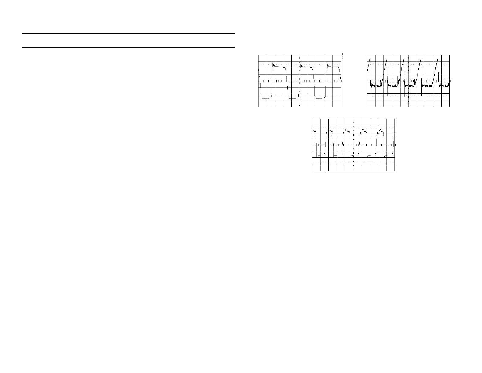
The waveforms below show what will be seen at Q621.
Q621/D - 50 mv, 10 us
Q621/S - 1 V, 10 us
Q621/G - 1 V, 10 us
Regulation
Changing the frequency of the switching regulates the output voltage at
the secondary winding comprised of T621/8 and 9. Taking a sample voltage from T621/4 and applying it to rectifiers D624 and D625 does this. As
this voltage rises and falls, the rectified voltage is applied to Q622/B through
R634. When Q622 begins to conduct, it lowers the voltage at Q621/G
and changes the switching frequency.
The changing frequency will change the amount of voltage coupled to the
secondary winding consisting of T621/8 and 9. If the load on the secondary output increases, the frequency of switching will decrease. This brings
the frequency of the converter closer to the optimum operating frequency
of T621 SRT. Moving closer to this optimum frequency causes more
voltage to be provided at T621/9. The opposite occurs when the load on
the supply decreases. This causes the frequency of operation to be increased and the amount of voltage coupled to T621/9 to be decreased.
The supply typically operates at 45 kHz when the set is OFF and at about
30 kHz when the set is operating. The incoming line voltage also effects
the frequency of switching operation.
FB621
D621
D622
FROM
T601/1
AC Hi
SIDE
FROM
R623
&R664 AC
Lo SIDE
R639
4.7 OHMS
R640
S
C629
R637
C631
D623
D
Q621
2SK2845
C634
Q622
PROT.
R636
R631
R635
C630 R632
D698
D699
MTZ-T-77
-15 .
C699
D624
R633
R634
D626
RD6.2ESB2
C635
R638
D625
C633
D627
C636
T621
SRT
1
2
3
11
10
TO RY600
POWER RELAY
IC622
5V REG
7.2VDC
D628
4
9
BAO5T
IO
G
CN641
10
STANDBY
C650
+5V TO
A BOARD
CN1641
C637
5
6
8
TO Q646/E
BACKUP
G BOARD
STANDBY SUPPLY
10
3 CTV26 1187
12/28/99

11
Over Current Protection (OCP)
Monitoring the voltage across R637 is used for over current protection.
This voltage is representative of the amount of current flowing through
Q621 Converter since it is in series with the transistor. If this voltage
should rise to .6 volts, it will cause Q622 to turn ON. If Q622 were to turn
ON, it would shunt Q621/G voltage to ground. This would cause Q621
Converter to stop conducting.
Over Voltage Protection (OVP)
Over voltage protection is done by rectifying the voltage at T621/6 with
D627. This voltage is filtered by C636 and applied to D626 through R638.
If this voltage should rise above 6.2 volts, D626 begins to conduct. When
its conduction allows Q622 Protect to turn ON, over voltage protection is
employed. Q622 Protect turns ON and grounds Q621/G, which stops the
converter from switching.
D699 is also used for OVP. The signal from T621/4 is rectified by D698.
This creates a negative voltage across C699. If this negative voltage
becomes great enough, D699 conducts and the Q621/G voltage is brought
lower.
Secondary Output
The power coupled through T621 SRT places a voltage on T621/9 that,
when rectified and filtered by D628 and C637, is 7.2 volts. This voltage is
constant due to the regulation circuit on the primary side of T621 SRT.
This 7.2 volts is applied to Q646/E for backup during the start of regulation by the regular power supply.
It is also applied to IC622 5-Volt Regulator, which regulates its output to 5
volts. This 5 volts is sent to CN641/10 which connects to the A board and
powers the Tuning Micon and other circuits. It is also applied to RY600
Power Relay.
Checking Q621
Testing a MOSFET device is simple. The leads show infinite resistance
to each other except for drain to source in one direction because of the
presence of a protection diode.
To prove the device is functional:
1. Connect the negative lead of the ohmmeter to the SOURCE lead.
2. Touch the ohmmeter positive lead to the gate, to pre-charge it.
3. Connect the ohmmeter positive lead to the DRAIN. If the device is
good you will get a resistance reading of about 400-1k ohms.
Some DVMs do not produce enough DC voltage in the ohms mode. The
diode check mode can be used with these models. When using the diode
mode, a low voltage drop is shown after pre-charging the gate.

FB621
D621
D622
FROM
T601/1
AC Hi
SIDE
FROM
R623
&R664 AC
Lo SIDE
R639
4.7 OHMS
R640
S
C629
R637
C631
D623
D
Q621
2SK2845
C634
Q622
PROT.
R636
R631
R635
C630 R632
D698
D699
MTZ-T-77
-15 .
C699
D624
R633
R634
D626
RD6.2ESB2
C635
R638
D625
C633
D627
C636
T621
SRT
1
2
3
11
10
TO RY600
POWER RELAY
IC622
5V REG
7.2VDC
D628
4
9
BAO5T
IO
G
CN641
10
STANDBY
C650
+5V TO
A BOARD
CN1641
C637
5
6
8
TO Q646/E
BACKUP
G BOARD
STANDBY SUPPLY
12
3 CTV26 1187
12/28/99
 Loading...